2011 Electric Service Requirements Manual, 2nd - Pacific Power
2011 Electric Service Requirements Manual, 2nd - Pacific Power
2011 Electric Service Requirements Manual, 2nd - Pacific Power

Create successful ePaper yourself
Turn your PDF publications into a flip-book with our unique Google optimized e-Paper software.
<strong>2011</strong> <strong>Electric</strong> <strong>Service</strong> <strong>Requirements</strong>, 2 nd Edition<br />
Errata Sheet: corrections included in the 2 nd edition<br />
(following the Jan <strong>2011</strong> 1 st edition; corrections published 5/9/11)<br />
Section 5:<br />
page 25: In Section 5.4.1, requirement number 5, the second sentence was removed for clarity.<br />
(It previously read, “Generators and their meters shall not be located within 25 feet of tanks.”)<br />
page 27: Figure 5.5.1 includes the following changes:<br />
1. For non-metallic equipment, a sentence was added beneath the exisitng one to the left of the image.<br />
The new sentence reads, “Greater separation may be needed for conduit and minimum sweep requirements.”<br />
2. The label to the right of the power pole image was changed from “power pole” to “<strong>Power</strong> Company pole.”<br />
In Figure 5.5.2, the descriptor “wall” was changed to “wall or eave.”<br />
page 28: The clearance distance from fire hydrants was corrected in Section 5.5, requirement 10. What<br />
previously read, “A 20-foot clearance between fire hydrants and oil-filled equipment shall be maintained. Ten<br />
(10) feet between fire hydrants and non oil-filled equipment shall be maintained,” was changed to:<br />
A minimum 6-foot (6') clearance between fire hydrants and metallic padmounted equipment shall be<br />
maintained. This clearance may be reduced to 4 feet (4') for non-metallic equipment. Greater separation may<br />
be required by local ordinances.<br />
Section 6:<br />
page 33: In Table 6.2.1.1, Conduit Sizes, Run Lengths, and Bend Limits, the former row for 401 -800<br />
amps was separated into two rows, so that 401 -600 and 601 -800 amp loads may have different conduit<br />
quantities (“two 4-inch” and “three 4-inch” respectively). In the note beneath Table 6.2.1.1, a typographical<br />
error was fixed; “is” was changed to “in.”<br />
Section 7:<br />
page 41: In Section 7.5.1, a reference to the HUD Handbook was corrected to instead reference the<br />
Permanent Foundations Guide for Manufactured Housing.<br />
page 53: Figure 7.8.3 was changed from an overhead-to-overhead example to the more typical overheadto-underground<br />
type of installation.<br />
A specification for steel conduit as the material for the service mast was removed from the header of the first<br />
column in Table 7.8.3. The title of that column now reads, “<strong>Service</strong> Mast.”<br />
Section 9:<br />
page 62: In Figure 9.1, Street Lighting Points of Connection, the label on the equipment base was changed<br />
from “padvault” to “padbox, padvault or pedestal”. Also, the provider for the 1”-minimum conduit to the<br />
secondary box was corrected. What previously read, “1” min. conduit to secondary box (<strong>Power</strong> Companyprovided);<br />
2” min. conduit to transformer (customer-provided)” was changed to:<br />
1”-min. conduit (customer-provided) to <strong>Power</strong> Company source.<br />
(A 90° sweep is required for pedestals or padboxes. Padvaults require a 1” -to -2” reducer, or 2” conduit.)<br />
page 67: In requirements 3 and 4 beneath the figures, uncecessary instructions to see figures (9.9.2 and<br />
9.9.3 respectively) were removed.<br />
Section 10:<br />
page 79: In the second paragraph of Section 10.8, a section reference was corrected (from 10.12 to 10.14).<br />
page 95: Obsolete table 10.14.4.1 was removed. References to that table now point to Table 10.14.4.<br />
page 96: A table reference was corrected (from Table 10.14.4.2 to Table 10.14.4).<br />
page 103: In Section 10.15.2, the reference to ESR White Paper 10 - Primary Cable <strong>Service</strong>s was<br />
removed. In Figure 10.15.4.1, a minimum cover depth of 30” was added atop primary conduit, and<br />
extraneous notes (the sentences formerly in italics, beginning with “Distances less than 6’...” and “Also see<br />
Section 5.5...”) within the figure were removed .
<strong>2011</strong> <strong>Electric</strong> <strong>Service</strong> <strong>Requirements</strong>, 2 nd Edition<br />
This page is left blank intentionally.
This edition of the Six-State <strong>Electric</strong> <strong>Service</strong> <strong>Requirements</strong> manual supersedes all previous editions.<br />
The publication date of this manual is January 7, <strong>2011</strong>. The requirements in this<br />
publication will be enforced on any installation made after April 1, <strong>2011</strong>.<br />
The purpose of this manual is to clarify electric service requirements for <strong>Pacific</strong> <strong>Power</strong> and<br />
Rocky Mountain <strong>Power</strong> customers and contractors prior to and during construction. This manual<br />
may require different electrical equipment than was previously used in <strong>Pacific</strong> <strong>Power</strong> and Rocky<br />
Mountain <strong>Power</strong> service areas.<br />
This manual has been updated to comply with the National <strong>Electric</strong> Safety Code (NESC), the<br />
National <strong>Electric</strong>al Code (NEC), and the <strong>Electric</strong> Utility <strong>Service</strong> Equipment <strong>Requirements</strong><br />
Committee (EUSERC). EUSERC is a voluntary organization (of which <strong>Pacific</strong> <strong>Power</strong> and Rocky<br />
Mountain <strong>Power</strong> are members) which strives to standardize electric utility requirements.<br />
Revisions to this publication since November 30, 2006, are marked with black revision bars.<br />
Noteworthy changes in this edition include:<br />
<br />
The customer is no longer required to provide a screw-type sealing ring for meter<br />
installations. (Section 3.4.1)<br />
Safety sockets for all direct-connect non-residential services are required; link by-pass is<br />
required for class 320 services. (Section 10.4)<br />
For multiple services, a disconnect for each service is now required. (Section 10.4)<br />
<br />
<br />
<strong>Requirements</strong> for single-family and duplex dwellings have been consolidated into one section.<br />
(Section 7)<br />
A new section on special installations and their associated requirements has been added.<br />
(Section 9)<br />
<strong>Pacific</strong> <strong>Power</strong> and Rocky Mountain <strong>Power</strong> strongly recommend contacting the <strong>Power</strong> Company<br />
with questions concerning the requirements in this manual. To submit suggestions for future<br />
editions of this manual, use the “Contact Us” link at the bottom of the websites:<br />
www.pacificpower.net\ESR and www.rockymountainpower.net\ESR.<br />
We will do our best to meet your needs for electrical service in a safe and economical manner.<br />
Construction lead time varies with work load. Please contact the <strong>Power</strong> Company early in<br />
your construction process.<br />
Brett Allsup, P.E.<br />
Vice President<br />
Engineering and Asset Management<br />
<strong>Pacific</strong> <strong>Power</strong><br />
Douglas N. Bennion, P.E.<br />
Vice President<br />
Engineering <strong>Service</strong>s and Capital Investment<br />
Rocky Mountain <strong>Power</strong><br />
This manual is published by PacifiCorp T & D Standards Engineering Documentation in Portland, Oregon.<br />
Employees of PacifiCorp can order this manual through the internal Online Forms Ordering site at http://69.30.123.235.<br />
Questions and requests for single copies may be directed to the editor, Sara Regan, at sara.regan@pacificorp.com or (503) 813−5293.
<strong>2011</strong> <strong>Electric</strong> <strong>Service</strong> <strong>Requirements</strong>, 2 nd Edition<br />
This page is left blank intentionally.
<strong>2011</strong> <strong>Electric</strong> <strong>Service</strong> <strong>Requirements</strong>, 2 nd Edition<br />
Single-Family and Duplex Dwelling Connection Checklist<br />
A customer building a new single-family or duplex dwelling and connecting to the <strong>Power</strong> Company’s<br />
electrical system may follow this checklist as a guide. This applies to manufactured and mobile homes<br />
as well.<br />
Obtain all necessary building and zoning permits.<br />
<br />
Complete the Rocky Mountain <strong>Power</strong> or <strong>Pacific</strong> <strong>Power</strong> application for new electric service at:<br />
https://www.rockymountainpower.net/con/bsrf.wcssn.html<br />
https://www.pacificpower.net/con/bsrf.wcssn.html<br />
Verify electrical inspection requirements for your jurisdiction.<br />
Meet with a <strong>Power</strong> Company representative to design your service.<br />
Read Section 1, General <strong>Requirements</strong>.<br />
Read Section 2, Permits and Applications.<br />
Read Section 3, <strong>Service</strong>s and Meter Installations.<br />
Review the definitions in the preface of this manual.<br />
Determine single-phase service requirements:<br />
<strong>Service</strong> Size: 200 amp____ 400 amp____<br />
<strong>Service</strong> Type: Overhead____ Underground____<br />
(See Figure 7.3.1) (See Figure 7.3.2)<br />
Select the meter socket enclosure (see the metering requirements in Section 7.3).<br />
Discuss additional requirements with a <strong>Power</strong> Company representative if your service is greater<br />
than 100 feet from <strong>Power</strong> Company facilities, if your service is over 400 amps, or if your service<br />
involves other special considerations.<br />
Notify the local underground locating services (811) before you dig, or refer to Table 1.12 for<br />
other contact options.<br />
Contact the local <strong>Power</strong> Company representative, or call the <strong>Power</strong> Company at<br />
1−888−221−7070, to request trench and conduit inspection prior to backfilling.<br />
Check the type of service:<br />
Temporary service. (Minimum pole length for a temporary service is 20 feet, and minimum<br />
pole length for permanent service is 25 feet; see Section 4 for temporary construction<br />
service requirements.)<br />
Overhead service to a single-family dwelling. (See Section 5 for clearances and Section 7<br />
for service requirements.)<br />
Underground service to a single-family dwelling. (See Section 5 for clearances, Section 6<br />
for trenching requirements, and Section 7 for service requirements.)<br />
Request electrical inspection by state/county/city.<br />
Date approved: __________________<br />
Call the <strong>Power</strong> Company to request installation of the meter and attachment of the service<br />
conductors.<br />
NOTES:<br />
Completing this list does not guarantee <strong>Power</strong> Company approval of the installation.<br />
Contractors installing multiple units should review all sections of this manual.<br />
i
<strong>2011</strong> <strong>Electric</strong> <strong>Service</strong> <strong>Requirements</strong>, 2 nd Edition<br />
This page is left blank intentionally.<br />
iv
<strong>2011</strong> <strong>Electric</strong> <strong>Service</strong> <strong>Requirements</strong>, 2 nd Edition<br />
Definitions<br />
ANSI — American National Standards Institute.<br />
Arc flash hazard — A dangerous condition associated with the release of energy caused by an electric arc.<br />
Bushings — Plastic or nylon rings that attach to the ends of conduit to protect the electrical cable from sharp<br />
edges.<br />
Bypass — A method which allows for service continuity to the customer while the meter is removed for test<br />
or inspection.<br />
Common meter — A non-residential meter for general energy use in apartment complexes, multi-use, or<br />
other multi-occupancy buildings. General energy use includes common area and exterior lighting, irrigation,<br />
laundry rooms, etc. Also called a house meter.<br />
CT — Current transformer (see Current transformer).<br />
Current transformer — A set of coils that reduce the primary current to the customer by a known ratio to<br />
an amount within the current capacity of the meter.<br />
Current transformer meter — A meter that requires current transformers because its current capacity is<br />
not as large as the customer’s current load.<br />
Customer — The individual requesting electrical service from <strong>Pacific</strong> <strong>Power</strong> or Rocky Mountain <strong>Power</strong>.<br />
Direct−connect meter — A meter energized to line voltage that carries all the load current. Also called a<br />
self-contained meter. No current transformer or voltage interface is used.<br />
Direct−connect socket — A meter socket connected to service wires, energized to line voltage and in series<br />
with the customer’s load without external instrument transformers. A self-contained meter is used in a direct-connect<br />
socket.<br />
Drip loop — The loop formed by the customer conductors that connects to the power company service<br />
drop. The conductors are formed in a downward “loop” so water will not enter the customer’s service<br />
mast (weatherhead).<br />
Dwelling unit — A single unit, providing complete and independent living facilities for one or more persons,<br />
including permanent provisions for living, sleeping, cooking, and sanitation.<br />
Dwelling, single-family — A building that consists solely of one dwelling unit.<br />
Dwelling, two−family — A building that consists solely of two dwelling units.<br />
Dwelling, multi-family — A building that contains three or more dwelling units.<br />
<strong>Electric</strong> vehicles — See EV below.<br />
ESRA — <strong>Electric</strong> <strong>Service</strong> <strong>Requirements</strong> Agreement, a formal, written agreement between the Company<br />
and the customer that describes the details of each installation. A <strong>Power</strong> Company representative fills out<br />
the ESRA during the design process.<br />
EUSERC (<strong>Electric</strong> Utility <strong>Service</strong> Equipment <strong>Requirements</strong> Committee) — An association of electric utilities<br />
and manufacturers that creates standard designs for the interface between the electric utility’s service<br />
and the customer’s facility.<br />
EV — <strong>Electric</strong> vehicle. An automotive type vehicle for highway use such as passenger cars, buses, trucks,<br />
vans and neighborhood vehicles primarily propelled by an electric motor powered by electrical energy from<br />
rechargeable batteries or other source onboard the vehicle.<br />
v
<strong>2011</strong> <strong>Electric</strong> <strong>Service</strong> <strong>Requirements</strong>, 2 nd Edition<br />
EVSE — <strong>Electric</strong> vehicle supply equipment.<br />
Definitions (Continued)<br />
Fault current — The available current under bolted short-circuit conditions.<br />
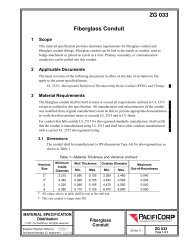
Fiberglass conduit — Rigid conduit made of UV-resistant fiberglass, colored black with red stripes (per<br />
PacifiCorp Material Specification ZG 033, Fiberglass Conduit, posted beneath this manual at<br />
www.pacificpower.net\ESR and www.rockymountainpower.net\ESR.)<br />
Free-standing metering assembly — A metering assembly not attached to a building.<br />
GO 95 — California General Order 95; state electrical codes for overhead line construction.<br />
GO 128 — California General Order 128; state electrical codes for underground electric supply.<br />
GMC — Galvanized metallic conduit.<br />
Grounding — Grounding in accordance with latest issue of NEC (Article 250, Grounding). Code enforcement<br />
agencies may require the ground connection to be visible when inspection is made. For safety reasons,<br />
the top of the ground rod should be flush or below ground level in permanent applications.<br />
The requirement for grounding per NEC Article 250 is displayed in this book with the following symbol:<br />
House meter — A non-residential meter for general energy use in apartment complexes, multi-use, or other<br />
multi-occupancy buildings. General energy use includes common area and exterior lighting, irrigation,<br />
laundry rooms, etc. Also called a common meter.<br />
HDPE conduit — A non-pressure-bearing conduit made from high density polyethlyene plastic. The<br />
<strong>Power</strong> Company limits the use of HDPE conduit for cable plowing and conduit boring. See PacifiCorp<br />
Material Specification ZG 031, HDPE Conduit, posted beneath this manual at www.pacificpower.net\ESR<br />
and www.rockymountainpower.net\ESR.<br />
Hub — A conduit attachment in, or out of, a meter base can, into which electrical connections may be<br />
plugged.<br />
IMC — Intermediate metallic conduit.<br />
Living space — An area within a structure where the environment is controlled for cooking, cleaning, entertaining<br />
or sleeping. A garage is not considered living space.<br />
Mandrel — A non-flexible wooden cylinder, with pulling eyes at each end, pulled through conduit to confirm<br />
the conduit’s integrity by testing for obstructions and/or flattening.<br />
<strong>Manual</strong> link bypass — A bypass facility requiring the physical act of placing links across the line and load<br />
bypass studs, for the purposes of removing the meter and preventing an outage while maintaining service<br />
continuity.<br />
Manufactured home — A factory−assembled structure or structures, site specific and transportable in one<br />
or more sections, designed to be used as a dwelling with a permanent foundation.<br />
Meter — A device that measures and records the summation of electrical quantity over a period of time.<br />
vi
<strong>2011</strong> <strong>Electric</strong> <strong>Service</strong> <strong>Requirements</strong>, 2 nd Edition<br />
Definitions (Continued)<br />
Meter socket continuous rating — The rating, in amperes, that a meter socket will continuously carry for<br />
three hours or more under stated conditions without exceeding the allowable temperature rise. Typical continuous<br />
duty ratings of sockets include 80, 160 and 320 Amps (ANSI C12.7).<br />
Meter socket maximum rating — The maximum rating of a meter socket in amperes; 125% of the continuous<br />
rating (EUSERC Section 300). Maximum ratings include 100, 200, and 400 Amps.<br />
Meter base — The mounting device consisting of jaws, connectors, and enclosure for socket-type meters.<br />
A mounting device may be either single or trough. The meter base is also referred to as a meter socket.<br />
Meter base ring — A metallic ring secured to the meter base that can be sealed by the power company.<br />
Meter pedestal — (Also see free-standing metering assembly.) A commercially-built pedestal that contains<br />
a meter base and customer disconnect switches.<br />
Metered service conductor — A conductor carrying customer load that is recorded by the <strong>Power</strong> Company’s<br />
billing meter.<br />
Mobile home — A factory-assembled structure or structures transportable in one or more sections, built on<br />
a permanent chassis and designed to be used as a dwelling without a permanent foundation.<br />
Modular home — A factory−assembled structure or structures transportable in one or more sections, built<br />
on a permanent chassis and designed to be used as a dwelling with a permanent foundation.<br />
NEC — The most recent publication of the National <strong>Electric</strong>al Code adopted by the state.<br />
NEMA — National <strong>Electric</strong>al Manufacturers’ Association.<br />
NEMA 3R — A rating for water-tight enclosures, for any electrical equipment, indoors or outdoors.<br />
NESC — The most recent publication of the National <strong>Electric</strong>al Safety Code adopted by the state.<br />
Net metering — A debit and credit metering process in an account in which the customer owns and operates<br />
a qualified generating device that interconnects with the <strong>Power</strong> Company’s electrical facilities. Net metering<br />
tariffs are available upon request.<br />
Network metering — Single-phase service obtained from two of the phase wires and the neutral of a 4-wire<br />
system.<br />
NFGC — The most recent publication of the National Fuel Gas Code.<br />
Non-residential service — <strong>Service</strong> to any customer who does not qualify for residential service.<br />
On-demand water heater — See tankless water heater.<br />
OSHA — Occupational Safety and Health Administration.<br />
Overhead service — See service drop.<br />
PacifiCorp — The company of PacifiCorp doing business as <strong>Pacific</strong> <strong>Power</strong> in the states of Oregon,<br />
Washington and California, and doing business as Rocky Mountain <strong>Power</strong> in the states of Utah, Wyoming<br />
and Idaho.<br />
Phase converter — Any machine, circuit or device used to create additional phases for operating polyphase<br />
motors or multi-phase devices from a single phase source.<br />
Plumb — (In this book, this term refers to the meter base.) Having the sides and front of the meter base<br />
perfectly vertical from both the front and side views.<br />
Point of delivery — See service point.<br />
Post — A pressure or thermally treated wooden structure that supports an underground service meter base.<br />
<strong>Power</strong> Company — See PacifiCorp.<br />
vii
<strong>2011</strong> <strong>Electric</strong> <strong>Service</strong> <strong>Requirements</strong>, 2 nd Edition<br />
Definitions (Continued)<br />
Primary <strong>Service</strong>: <strong>Service</strong>s with delivery voltages greater than 600 volts.<br />
Primary voltage — Over 600 volts.<br />
<strong>Power</strong> factor — The cosine of the angle, expressed as a percent, between voltage and current. Also, the ratio<br />
of the active power to the apparent power.<br />
PVC conduit — A gray-colored plastic pipe approved for use in electrical installations. Commonly referred<br />
to as polyvinylchloride pipe.<br />
Residential service — <strong>Service</strong> furnished to customers for domestic purposes in single-family or duplex<br />
dwellings, or as defined by tariff.<br />
Relocation — A change in location of any of the following electrical system components: 1) the meter base/<br />
socket, 2) the service drop, 3) the service lateral, or 4) the service entrance conductors.<br />
Rewire — Work performed on electrical wiring that requires any of the following: 1) re-installation of the<br />
meter base/socket, 2) replacement of the service drop, 3) replacement of the service lateral, or<br />
4) replacement of the service entrance conductors.<br />
RMC — Rigid metallic conduit.<br />
SAE — Society of Automotive Engineers.<br />
Safety socket — A device consisting of a manual link bypass facility and a circuit closing nut and bolt<br />
assembly which de-energize the meter socket while the meter is removed for test or inspection.<br />
Secondary voltage — 600 volts and under.<br />
Self-contained meter — A watt-hour meter connected directly to the supply voltage that is in series<br />
with the customer’s load without external instrument transformers.<br />
Select backfill material — Material used to bed and cover direct-burial cables or conduits, consisting<br />
of screened native soil or sand free of sharp or foreign objects.<br />
<strong>Service</strong> — The conductors and equipment for delivering energy from the electric supply system to the<br />
wiring system of the premises served.<br />
<strong>Service</strong> conductors, underground system — See service lateral, underground.<br />
<strong>Service</strong> drop — The overhead service conductors from the utility’s pole, including the splices that connect<br />
to the customer’s service entrance conductors.<br />
<strong>Service</strong> drop attachment point — The location where the service drop conductors connect to the customer’s<br />
residence, building or structure.<br />
<strong>Service</strong> entrance conductors (customer-owned) — The conductors between the terminals of the<br />
service equipment connecting to the service point. In an overhead system, the customer installs and<br />
owns the wires (service entrance conductors) from the splices at the service head (weatherhead). In an<br />
underground system, the customer installs and owns the wires (service entrance conductors) from the<br />
meter.<br />
<strong>Service</strong> equipment — Customer-owned equipment, usually consisting of circuit breakers (or switches)<br />
and fuses, and their accessories, connected to the load end of service conductors to the customer’s structure,<br />
and intended to constitute the main control and cutoff of the supply.<br />
<strong>Service</strong> lateral, underground — The entire length of service conductors between the street main, including<br />
any risers at a pole or other structure, or from transformers, and the first point of connection to<br />
the service entrance conductors in a terminal box or meter or other enclosure, inside or outside the<br />
building wall. Where there is no terminal box, meter, or other enclosure, the point of connection is considered<br />
to be the point of entrance of the service conductors into the building.<br />
<strong>Service</strong> point — The point of connection between the facilities of the serving utility and the premises’<br />
wiring.<br />
viii
<strong>2011</strong> <strong>Electric</strong> <strong>Service</strong> <strong>Requirements</strong>, 2 nd Edition<br />
Definitions (Continued)<br />
<strong>Service</strong> trench — A trench provided by the customer for a service lateral.<br />
Socket — A mounting device consisting of jaws, connectors, and enclosure for socket-type meters.<br />
Spoil — Native material removed from a hole or trench that is piled above grade, adjacent to the hole<br />
or trench.<br />
Swedge — A smooth-walled reducer used to aid transitions between conduit and meter base knockout<br />
sizes.<br />
Sweep — A PVC, fiberglass or steel bend that changes the direction of the conduit.<br />
Switchboard — A large panel or assembly of panels which contains buses, current transformers, meters,<br />
switches, and protective devices.<br />
Tankless water heater — A water heating system (for hot water production and hot water heating systems)<br />
that heats only as needed, without the use of a storage tank. Also called an “on-demand,” “instantaneous,”<br />
“continuous-flow,” “in-flow,” or “instant-on” water heater.<br />
Tariff — A set of policies (or rules) and rates written by the <strong>Power</strong> Company, approved by the Public<br />
<strong>Service</strong> and Public Utility Commissions of each state served. All sections of the tariff are subject to updates<br />
at any time. Individual state rules may affect the <strong>Power</strong> Company’s tariff. Tariff policy provides<br />
the working rules by which the <strong>Power</strong> Company serves its customers.<br />
Test block facility (TBF) — An assembly used to bypass a self-contained meter socket.<br />
Test bypass facility (TBF) — See test block facility (above).<br />
Test switch — A device used by the <strong>Power</strong> Company to isolate the meter from current and voltage<br />
sources.<br />
Timber — A pressure or thermally treated wooden structure that supports an overhead service. Length<br />
depends upon the type of installation; see Section 7.8.3 for permanent construction and Section 4.2 for<br />
temporary construction.<br />
Underground cable — <strong>Electric</strong>al cable approved by a Nationally Recognized Testing Laboratory<br />
(NRTL) suitable for direct burial in the ground or in conduit.<br />
Underground service — <strong>Electric</strong> service supplied to the customer from the power company utilizing<br />
underground conductors.<br />
Unmetered service conductor — A conductor carrying customer load that is not measured by the<br />
<strong>Power</strong> Company’s billing meter.<br />
Unused facility — A facility that exists with no recorded customer or contractual obligation for a<br />
length of time (specified by the State).<br />
ix
<strong>2011</strong> <strong>Electric</strong> <strong>Service</strong> <strong>Requirements</strong>, 2 nd Edition<br />
This page is left blank intentionally.<br />
x
<strong>2011</strong> <strong>Electric</strong> <strong>Service</strong> <strong>Requirements</strong>, 2 nd Edition<br />
Table of Contents<br />
1 General <strong>Requirements</strong> . . . . . . . . . . . . . . . . . . . . . . . . . . . . . . . . . . . . . . . . . . . . . . . . 1<br />
1.1 <strong>Manual</strong> Purpose and Scope . . . . . . . . . . . . . . . . . . . . . . . . . . . . . . . . . . . . . . . . . . . . . . 1<br />
1.2 Customer and <strong>Power</strong> Company Defined . . . . . . . . . . . . . . . . . . . . . . . . . . . . . . . . . . . . 1<br />
1.3 Consulting the <strong>Power</strong> Company . . . . . . . . . . . . . . . . . . . . . . . . . . . . . . . . . . . . . . . . . . . 1<br />
1.4 Changes or Conflicts in <strong>Requirements</strong> . . . . . . . . . . . . . . . . . . . . . . . . . . . . . . . . . . . . . 1<br />
1.5 Maximum Available Fault Current . . . . . . . . . . . . . . . . . . . . . . . . . . . . . . . . . . . . . . . . . . 2<br />
1.6 Customer’s Responsibility for Safety . . . . . . . . . . . . . . . . . . . . . . . . . . . . . . . . . . . . . . . 2<br />
1.7 Work Activity Near High-Voltage Overhead <strong>Power</strong> Lines (Over 600 Volts) . . . . . . 2<br />
1.8 Temporary <strong>Service</strong> Disconnect . . . . . . . . . . . . . . . . . . . . . . . . . . . . . . . . . . . . . . . . . . . . 2<br />
1.9 Grounding and Bonding . . . . . . . . . . . . . . . . . . . . . . . . . . . . . . . . . . . . . . . . . . . . . . . . . . 2<br />
1.10 Vegetation and Accessibility . . . . . . . . . . . . . . . . . . . . . . . . . . . . . . . . . . . . . . . . . . . . . . 3<br />
1.11 Customer Equipment on <strong>Power</strong> Company Poles . . . . . . . . . . . . . . . . . . . . . . . . . . . . . 3<br />
1.12 Call Before You Dig . . . . . . . . . . . . . . . . . . . . . . . . . . . . . . . . . . . . . . . . . . . . . . . . . . . . . . 3<br />
1.13 <strong>Power</strong> Quality . . . . . . . . . . . . . . . . . . . . . . . . . . . . . . . . . . . . . . . . . . . . . . . . . . . . . . . . . . 3<br />
1.14 <strong>Power</strong> Factor . . . . . . . . . . . . . . . . . . . . . . . . . . . . . . . . . . . . . . . . . . . . . . . . . . . . . . . . . . . 4<br />
1.15 Motors . . . . . . . . . . . . . . . . . . . . . . . . . . . . . . . . . . . . . . . . . . . . . . . . . . . . . . . . . . . . . . . . . 4<br />
1.16 Customer Generation . . . . . . . . . . . . . . . . . . . . . . . . . . . . . . . . . . . . . . . . . . . . . . . . . . . . 5<br />
2 Permits and Applications . . . . . . . . . . . . . . . . . . . . . . . . . . . . . . . . . . . . . . . . . . . . . 7<br />
2.1 Codes, Ordinances, and Tariffs . . . . . . . . . . . . . . . . . . . . . . . . . . . . . . . . . . . . . . . . . . . . 7<br />
2.2 Rights−of−Way . . . . . . . . . . . . . . . . . . . . . . . . . . . . . . . . . . . . . . . . . . . . . . . . . . . . . . . . . 7<br />
2.3 Application for <strong>Service</strong> . . . . . . . . . . . . . . . . . . . . . . . . . . . . . . . . . . . . . . . . . . . . . . . . . . . 7<br />
2.4 <strong>Electric</strong> <strong>Service</strong> Requirement Agreement . . . . . . . . . . . . . . . . . . . . . . . . . . . . . . . . . . . 8<br />
2.5 Permits . . . . . . . . . . . . . . . . . . . . . . . . . . . . . . . . . . . . . . . . . . . . . . . . . . . . . . . . . . . . . . . . 8<br />
3 <strong>Service</strong>s and Meter Installations . . . . . . . . . . . . . . . . . . . . . . . . . . . . . . . . . . . . . . 9<br />
3.1 Types of <strong>Service</strong> Furnished . . . . . . . . . . . . . . . . . . . . . . . . . . . . . . . . . . . . . . . . . . . . . . . 9<br />
3.2 Load <strong>Requirements</strong> . . . . . . . . . . . . . . . . . . . . . . . . . . . . . . . . . . . . . . . . . . . . . . . . . . . . . . 9<br />
3.3 Permanent <strong>Service</strong> Connection . . . . . . . . . . . . . . . . . . . . . . . . . . . . . . . . . . . . . . . . . . . 10<br />
3.4 General Meter Installations . . . . . . . . . . . . . . . . . . . . . . . . . . . . . . . . . . . . . . . . . . . . . . . 10<br />
3.5 Connection, Disconnection, and Re-establishment of <strong>Service</strong> . . . . . . . . . . . . . . . . . 12<br />
3.6 Relocation of <strong>Service</strong>s and Facilities . . . . . . . . . . . . . . . . . . . . . . . . . . . . . . . . . . . . . . . 12<br />
4 Temporary Construction <strong>Service</strong> . . . . . . . . . . . . . . . . . . . . . . . . . . . . . . . . . . . . . . 13<br />
4.1 General . . . . . . . . . . . . . . . . . . . . . . . . . . . . . . . . . . . . . . . . . . . . . . . . . . . . . . . . . . . . . . . . 13<br />
4.2 Construction Criteria For Temporary <strong>Service</strong> . . . . . . . . . . . . . . . . . . . . . . . . . . . . . . . . 13<br />
4.3 Meter Socket <strong>Requirements</strong> for Temporary Construction <strong>Service</strong>s . . . . . . . . . . . . . 16<br />
5 Clearances . . . . . . . . . . . . . . . . . . . . . . . . . . . . . . . . . . . . . . . . . . . . . . . . . . . . . . . . . . 17<br />
5.1 Meter Clearances and Locations . . . . . . . . . . . . . . . . . . . . . . . . . . . . . . . . . . . . . . . . . . 17<br />
5.2 Clearances for <strong>Service</strong>s . . . . . . . . . . . . . . . . . . . . . . . . . . . . . . . . . . . . . . . . . . . . . . . . . . 21<br />
5.3 Conductors Near Pools, Spas or Hot Tubs . . . . . . . . . . . . . . . . . . . . . . . . . . . . . . . . . . 25<br />
5.4 Clearance from Fuel Storage Tanks . . . . . . . . . . . . . . . . . . . . . . . . . . . . . . . . . . . . . . . . 25<br />
5.5 Clearances From Padmounted Equipment and Pedestals . . . . . . . . . . . . . . . . . . . . . 27<br />
5.6 Firewalls (Blast Walls) . . . . . . . . . . . . . . . . . . . . . . . . . . . . . . . . . . . . . . . . . . . . . . . . . . . 29<br />
xi
<strong>2011</strong> <strong>Electric</strong> <strong>Service</strong> <strong>Requirements</strong>, 2 nd Edition<br />
6 Underground <strong>Requirements</strong> . . . . . . . . . . . . . . . . . . . . . . . . . . . . . . . . . . . . . . . . . . 31<br />
6.1 General . . . . . . . . . . . . . . . . . . . . . . . . . . . . . . . . . . . . . . . . . . . . . . . . . . . . . . . . . . . . . . . . 31<br />
6.2 Conduit <strong>Requirements</strong> . . . . . . . . . . . . . . . . . . . . . . . . . . . . . . . . . . . . . . . . . . . . . . . . . . . 31<br />
6.3 Trench and Backfill <strong>Requirements</strong> . . . . . . . . . . . . . . . . . . . . . . . . . . . . . . . . . . . . . . . . . 34<br />
7 Single-Family and Duplex Dwellings . . . . . . . . . . . . . . . . . . . . . . . . . . . . . . . . . . . 37<br />
7.1 General . . . . . . . . . . . . . . . . . . . . . . . . . . . . . . . . . . . . . . . . . . . . . . . . . . . . . . . . . . . . . . . . 37<br />
7.2 Maximum Available Fault Current . . . . . . . . . . . . . . . . . . . . . . . . . . . . . . . . . . . . . . . . . . 37<br />
7.3 Residential Meter Sockets . . . . . . . . . . . . . . . . . . . . . . . . . . . . . . . . . . . . . . . . . . . . . . . . 37<br />
7.4 Connection and Energizing . . . . . . . . . . . . . . . . . . . . . . . . . . . . . . . . . . . . . . . . . . . . . . . 40<br />
7.5 Manufactured and Mobile Homes . . . . . . . . . . . . . . . . . . . . . . . . . . . . . . . . . . . . . . . . . . 40<br />
7.6 Residential Meter Socket Location . . . . . . . . . . . . . . . . . . . . . . . . . . . . . . . . . . . . . . . . . 41<br />
7.7 Underground <strong>Service</strong> . . . . . . . . . . . . . . . . . . . . . . . . . . . . . . . . . . . . . . . . . . . . . . . . . . . . 43<br />
7.8 Overhead <strong>Service</strong> . . . . . . . . . . . . . . . . . . . . . . . . . . . . . . . . . . . . . . . . . . . . . . . . . . . . . . . 49<br />
8 Multiple Family <strong>Service</strong> . . . . . . . . . . . . . . . . . . . . . . . . . . . . . . . . . . . . . . . . . . . . . . . 55<br />
8.1 General . . . . . . . . . . . . . . . . . . . . . . . . . . . . . . . . . . . . . . . . . . . . . . . . . . . . . . . . . . . . . . . . 55<br />
8.2 Maximum Available Fault Current . . . . . . . . . . . . . . . . . . . . . . . . . . . . . . . . . . . . . . . . . . 55<br />
8.3 Multiple Residential Meter Sockets . . . . . . . . . . . . . . . . . . . . . . . . . . . . . . . . . . . . . . . . 55<br />
8.4 Pull Box <strong>Requirements</strong> . . . . . . . . . . . . . . . . . . . . . . . . . . . . . . . . . . . . . . . . . . . . . . . . . . . 57<br />
8.5 Multiple Family Meter Location, Underground <strong>Service</strong> . . . . . . . . . . . . . . . . . . . . . . . . 58<br />
8.6 Multiple Family Meter Location, Overhead <strong>Service</strong> . . . . . . . . . . . . . . . . . . . . . . . . . . . 59<br />
9 Special Installations . . . . . . . . . . . . . . . . . . . . . . . . . . . . . . . . . . . . . . . . . . . . . . . . . . 61<br />
9.1 Street Lighting Points of Connection . . . . . . . . . . . . . . . . . . . . . . . . . . . . . . . . . . . . . . . 61<br />
9.2 Multiple Use (Multi-Use) Buildings . . . . . . . . . . . . . . . . . . . . . . . . . . . . . . . . . . . . . . . . . 62<br />
9.3 Meter Rooms . . . . . . . . . . . . . . . . . . . . . . . . . . . . . . . . . . . . . . . . . . . . . . . . . . . . . . . . . . . 63<br />
9.4 Meter Access Platforms . . . . . . . . . . . . . . . . . . . . . . . . . . . . . . . . . . . . . . . . . . . . . . . . . . 63<br />
9.5 Marinas . . . . . . . . . . . . . . . . . . . . . . . . . . . . . . . . . . . . . . . . . . . . . . . . . . . . . . . . . . . . . . . . 65<br />
9.6 <strong>Electric</strong> Vehicles . . . . . . . . . . . . . . . . . . . . . . . . . . . . . . . . . . . . . . . . . . . . . . . . . . . . . . . . 65<br />
9.7 Recreational Vehicles (RV’s) . . . . . . . . . . . . . . . . . . . . . . . . . . . . . . . . . . . . . . . . . . . . . . 66<br />
9.8 Utility-Owned, Oil-Filled Equipment on Customer Property . . . . . . . . . . . . . . . . . . . . 66<br />
9.9 Barrier Posts . . . . . . . . . . . . . . . . . . . . . . . . . . . . . . . . . . . . . . . . . . . . . . . . . . . . . . . . . . . 66<br />
10 Non-Residential <strong>Service</strong>s (Commercial, Industrial, and Agricultural) . . . . . 69<br />
10.1 <strong>Service</strong> Point Location for Meter and Equipment . . . . . . . . . . . . . . . . . . . . . . . . . . . . . 69<br />
10.2 Clearances . . . . . . . . . . . . . . . . . . . . . . . . . . . . . . . . . . . . . . . . . . . . . . . . . . . . . . . . . . . . . 70<br />
10.3 General Descriptions . . . . . . . . . . . . . . . . . . . . . . . . . . . . . . . . . . . . . . . . . . . . . . . . . . . . 70<br />
10.4 Direct-Connect <strong>Service</strong>s . . . . . . . . . . . . . . . . . . . . . . . . . . . . . . . . . . . . . . . . . . . . . . . . . 71<br />
10.5 Non-Residential Underground <strong>Service</strong> Meter Pedestals . . . . . . . . . . . . . . . . . . . . . . . 75<br />
10.6 Direct-Connect Multiple Metering <strong>Service</strong>s . . . . . . . . . . . . . . . . . . . . . . . . . . . . . . . . . . 76<br />
10.7 Pull Box . . . . . . . . . . . . . . . . . . . . . . . . . . . . . . . . . . . . . . . . . . . . . . . . . . . . . . . . . . . . . . . . 78<br />
10.8 Current Transformer Metering − 600 Volts, 800 Amps Maximum . . . . . . . . . . . . . . . 79<br />
10.9 Current Transformer Location . . . . . . . . . . . . . . . . . . . . . . . . . . . . . . . . . . . . . . . . . . . . . 87<br />
10.10 Current Transformer Metering Conduit . . . . . . . . . . . . . . . . . . . . . . . . . . . . . . . . . . . . . 87<br />
10.11 Current Transformer Metering for Free-Standing Installations . . . . . . . . . . . . . . . . . . 88<br />
10.12 Current Transformer Enclosure Bonding . . . . . . . . . . . . . . . . . . . . . . . . . . . . . . . . . . . . 89<br />
10.13 Combination Self-Contained and Current Transformer Metering . . . . . . . . . . . . . . . 90<br />
10.14 Switchboard Metering . . . . . . . . . . . . . . . . . . . . . . . . . . . . . . . . . . . . . . . . . . . . . . . . . . . . 91<br />
10.15 <strong>Service</strong> at Primary Voltage (Over 600 Volts) . . . . . . . . . . . . . . . . . . . . . . . . . . . . . . . . 102<br />
10.16 Primary Metering − Customer-Owned Substation . . . . . . . . . . . . . . . . . . . . . . . . . . . . 104<br />
xii
<strong>2011</strong> <strong>Electric</strong> <strong>Service</strong> <strong>Requirements</strong>, 2 nd Edition<br />
Section 1<br />
1 General <strong>Requirements</strong><br />
1.1 <strong>Manual</strong> Purpose and Scope<br />
This manual was prepared to aid customers in obtaining service from the <strong>Power</strong> Company.<br />
This manual applies to new services, relocated services, house relocations, and rewired services.<br />
If additional information is required, please contact the <strong>Power</strong> Company at 1−888−221−7070 or<br />
via the internet at www.pacificpower.net or www.rockymountainpower.net.<br />
The <strong>Power</strong> Company has published “ESR white papers” to provide more information on certain<br />
topics in this manual. These white papers are posted online at www.pacificpower.net/esr and<br />
www.rockymountainpower.net/esr, beneath the sections to which they pertain. When a white<br />
paper is available on a topic in this manual, it is noted with the following symbol:<br />
The white papers are provided as additional helpful information and commentary (not as<br />
supplemental rules). The information and requirements in this manual supersede the white papers.<br />
In addition to the white papers, customers may reference the <strong>Power</strong> Company’s tariffs, located on<br />
the “Rates and Regulations” web pages at www.pacificpower.net/bus/rr.html and<br />
www.rockymountainpower.net/bus/rr.html.<br />
This manual shall be distributed and interpreted in its entirety. Individual pages will not represent<br />
all the requirements necessary for an installation.<br />
1.2 Customer and <strong>Power</strong> Company Defined<br />
The term <strong>Power</strong> Company in this book refers to PacifiCorp, doing business as <strong>Pacific</strong> <strong>Power</strong> or<br />
Rocky Mountain <strong>Power</strong>.<br />
The term customer is the party requesting electrical service from the <strong>Power</strong> Company or their<br />
authorized agent.<br />
1.3 Consulting the <strong>Power</strong> Company<br />
The instruction “consult the <strong>Power</strong> Company” indicates that the customer shall initiate discussion<br />
with a <strong>Power</strong> Company representative and shall obtain written approval from the <strong>Power</strong> Company<br />
prior to installation for special situations, meter base locations, metering equipment locations, and<br />
any deviations from the requirements set forth in this book. Failure to receive prior written<br />
approval will result in denial of service until the installation meets the <strong>Power</strong> Company’s<br />
approval.<br />
Prior written approval requires that the customer and <strong>Power</strong> Company management discuss the<br />
project details before or during construction. Construction shall be conducted in accordance with<br />
the <strong>Electric</strong> <strong>Service</strong> <strong>Requirements</strong> Agreement.<br />
1.4 Changes or Conflicts in <strong>Requirements</strong><br />
This manual is written with the intent to comply with all applicable codes, ordinances, and tariffs,<br />
as well as to implement common practices throughout the <strong>Power</strong> Company’s service territory.<br />
Common practices are implemented to:<br />
meet or exceed minimum safety codes and municipal building ordinances,<br />
This manual shall be distributed and interpreted in its entirety. Individual pages will not represent all the requirements necessary for an installation.<br />
1
Section 1<br />
<strong>2011</strong> <strong>Electric</strong> <strong>Service</strong> <strong>Requirements</strong>, 2 nd Edition<br />
<br />
<br />
<br />
ensure fair and impartial requirements for all customers,<br />
use safe work procedures by following established <strong>Power</strong> Company standards, and<br />
facilitate the privacy and security of current and future customers and occupants.<br />
This manual cannot address every possible situation. Consult the <strong>Power</strong> Company for solutions to<br />
unique circumstances which may require special consideration to meet the intents of this manual.<br />
These <strong>Electric</strong> <strong>Service</strong> <strong>Requirements</strong> may change if governing codes, ordinances, or tariffs<br />
change. If a requirement in this manual conflicts with an applicable tariff, code, or ordinance, then<br />
other <strong>Power</strong> Company standards shall be used to design a solution that meets (or exceeds) the<br />
minimum requirements of the tariff, code, or ordinance. The <strong>Power</strong> Company will provide the<br />
standards, and should be consulted with questions on the applicability of any item in this manual.<br />
1.5 Maximum Available Fault Current<br />
The customer shall furnish equipment to withstand bolted fault currents. Upon request, the <strong>Power</strong><br />
Company will supply information on the maximum fault current available at the customer’s<br />
service entrance.<br />
1.6 Customer’s Responsibility for Safety<br />
The customer shall comply with federal, state, and local laws and regulations concerning activities<br />
in the vicinity of the <strong>Power</strong> Company’s electrical lines and equipment. The customer shall comply<br />
with all laws and regulations to protect themselves, their family, their employees, the <strong>Power</strong><br />
Company and its employees, contractors, and all third parties from injury, loss, or damage.<br />
1.7 Work Activity Near High-Voltage Overhead <strong>Power</strong> Lines (Over 600 Volts)<br />
State statute and Federal OSHA laws require that no work take place within 10 feet (10') of any<br />
high-voltage overhead power line. Some lines require even greater clearance. Work performed<br />
with derricks or cranes within 20 feet (20') of overhead power lines is subject to additional rules.<br />
Minimally, the following requirements apply:<br />
1. The customer shall notify the <strong>Power</strong> Company of the intended work activity a minimum of<br />
three working days prior to construction work. Longer lead times may be required,<br />
depending on the type of work to be done.<br />
2. The customer and the <strong>Power</strong> Company shall agree upon a mutually satisfactory method of<br />
accomplishing the activity safely.<br />
3. The customer is responsible for complying with federal, state, and local clearance and safety<br />
rules.<br />
1.8 Temporary <strong>Service</strong> Disconnect<br />
Ensuring safe work practices on customer-owned equipment may require a temporary service<br />
disconnect from the <strong>Power</strong> Company’s facilities; please contact the <strong>Power</strong> Company to coordinate<br />
disconnection.<br />
To safely maintain or upgrade <strong>Power</strong> Company facilities, a temporary service disconnect or<br />
interruption may be initiated by the <strong>Power</strong> Company.<br />
Planned disconnects are normally scheduled 48 hours in advance.<br />
1.9 Grounding and Bonding<br />
Grounding and bonding is critical for safety and electrical reliability. The customer is responsible<br />
for ensuring that electrical wiring and service equipment is grounded and bonded in accordance<br />
with applicable NEC requirements.<br />
2<br />
This manual shall be distributed and interpreted in its entirety. Individual pages will not represent all the requirements necessary for an installation.
<strong>2011</strong> <strong>Electric</strong> <strong>Service</strong> <strong>Requirements</strong>, 2 nd Edition<br />
Section 1<br />
1.10 Vegetation and Accessibility<br />
The customer shall prepare and maintain the premises such that trees, shrubs, or other vegetation<br />
do not interfere with <strong>Power</strong> Company access to poles, padmounted equipment, overhead<br />
equipment, underground conduit, or metering equipment. (See Section 5, Clearances.)<br />
1.11 Customer Equipment on <strong>Power</strong> Company Poles<br />
Customer-owned metering equipment, switching devices, conduits, conductors, luminaires, etc.,<br />
shall not be mounted on a <strong>Power</strong> Company pole.<br />
1.12 Call Before You Dig<br />
State laws require the customer/excavator to call for underground utility cable locations.<br />
Excavation shall not start until locations have been marked or the utilities have informed the<br />
excavator that they have no facilities in the area. Before digging, refer to Table 1.12 and call the<br />
specified phone number. Excavations require prior notice of at least 48 hours.<br />
Table 1.12 − “Call Before You Dig” Contacts<br />
State Phone / Website Hrs. Name Comments<br />
Oregon<br />
Washington<br />
Idaho<br />
California<br />
811 or 800−332−2344<br />
www.callbeforeyoudig.org<br />
811 or 800−424−5555<br />
www.callbeforeyoudig.org<br />
811 or 800−342−1585<br />
www.digline.com<br />
811 or 800−227−2600<br />
www.usanorth.org<br />
24/7 Oregon Utility<br />
Notification Center<br />
24/7 Utilities Underground Location Center<br />
(UULC)<br />
Northwest Utilities Notification Center<br />
(NWUNC)<br />
Locate requests can be<br />
filed online.<br />
Locate requests can be<br />
filed online.<br />
24/7 Utility Dig Line <strong>Service</strong> of Idaho Locate requests can be<br />
filed online.<br />
6−7<br />
M−F<br />
Underground <strong>Service</strong> Alert (USA)<br />
Closed on holidays.<br />
Wyoming<br />
Utah<br />
811 or 800−849−2476<br />
www.onecallofwyoming.com<br />
811 or 800−662−4111<br />
www.bluestakes.org<br />
24/7 One Call of Wyoming Locate requests can be<br />
filed online.<br />
7−5<br />
M−F<br />
Blue Stakes Utility Notification Center<br />
Closed weekends and<br />
holidays.<br />
Locate requests can be<br />
filed online.<br />
Note: In certain areas of Oregon and Washington, the status of One-Call tickets can be tracked at<br />
www.searchandstatus.com or (800) 822−1974. The website allows searching and ticket printing.<br />
1.13 <strong>Power</strong> Quality<br />
1.13.1 General<br />
The characteristics of the customer’s electrical equipment and devices must allow the<br />
<strong>Power</strong> Company distribution system to operate efficiently without undue interference to<br />
the <strong>Power</strong> Company’s service or to other customers. When a customer’s equipment has<br />
characteristics which cause undue interference with <strong>Power</strong> Company service to other<br />
customers, the customer shall make equipment changes or provide, at customer expense,<br />
additional equipment to eliminate the interference.<br />
This manual shall be distributed and interpreted in its entirety. Individual pages will not represent all the requirements necessary for an installation.<br />
3
Section 1<br />
<strong>2011</strong> <strong>Electric</strong> <strong>Service</strong> <strong>Requirements</strong>, 2 nd Edition<br />
To eliminate the possibility of equipment interference, the customer should submit to the<br />
<strong>Power</strong> Company prior to installation all information regarding equipment which might<br />
cause power quality problems.<br />
The <strong>Power</strong> Company’s power quality standards are located online at:<br />
www.pacificpower.net/con/pqs.html and www.rockymountainpower.net/con/pqs.html.<br />
1.13.2 Voltage Performance<br />
<strong>Electric</strong> service supplied by the <strong>Power</strong> Company may be subject to voltage disturbances<br />
which do not normally affect the performance of typical electrical equipment. These<br />
disturbances may result in the improper operation of voltage-sensitive equipment, such as<br />
computers or microprocessors. The customer shall provide any power-conditioning devices<br />
needed to obtain the quality of power necessary for optimum performance of<br />
voltage-sensitive equipment. Devices between the meter and the socket may be allowed at<br />
the sole discretion of the <strong>Power</strong> Company. Consult the <strong>Power</strong> Company for specific policies.<br />
1.13.3 Harmonics<br />
The effects of the design and operation of high-frequency equipment such as electronic<br />
heating systems, spark discharge devices, radio transmitting equipment, etc., and equipment<br />
that generates harmonics, such as an induction furnace, shall not create disturbances on the<br />
<strong>Power</strong> Company’s electrical system which interfere with any other customer’s proper<br />
operation of communication, radio, television, remote control, or other equipment.<br />
Devices which can produce harmonic distortion (such as adjustable speed drives, electronic<br />
ballasts for fluorescent lighting, and switching power supplies for computers and electric<br />
vehicles) shall be filtered such that the harmonic distortion caused by these devices is kept<br />
within the limits specified in the Institute of <strong>Electric</strong>al and Electronics Engineers (IEEE)<br />
Standard 519, Section 10. Compliance with this requirement is judged by the <strong>Power</strong><br />
Company’s measurement at the service point, otherwise known as “the point of common<br />
coupling.”<br />
The customer can more easily stay within harmonic distortion limits by requiring their<br />
supplier to provide “low harmonic current distortion” equipment.<br />
1.14 <strong>Power</strong> Factor<br />
The <strong>Power</strong> Company’s currently filed tariffs charge for “low power factor” for certain commercial,<br />
agricultural and industrial customers. Low power factor may cause inferior performance of the<br />
customer’s electrical system. The <strong>Power</strong> Company recommends that the customer install corrective<br />
devices to make the most effective use of the electrical system. The <strong>Power</strong> Company can provide a<br />
copy of the tariff if the customer would like to determine potential savings during design.<br />
1.15 Motors<br />
1.15.1 Protection<br />
To ensure adequate safety to personnel and equipment, the customer is responsible for providing<br />
and maintaining code-approved protective devices to protect motors against overloading, short<br />
circuits, ground faults, low voltage, and single-phasing of three-phase motors.<br />
1.15.2 Starting<br />
Motor starts may cause unacceptable voltage dips to adjacent customers or on the<br />
customer’s premises. Frequently started motors, three-phase motors rated larger than 35 hp<br />
4<br />
This manual shall be distributed and interpreted in its entirety. Individual pages will not represent all the requirements necessary for an installation.
<strong>2011</strong> <strong>Electric</strong> <strong>Service</strong> <strong>Requirements</strong>, 2 nd Edition<br />
Section 1<br />
served from a three-phase system, or single-phase motors larger than 3 hp may require<br />
reduced-voltage or soft-start motor controls. Three-phase motors on a single-phase system<br />
with a phase converter may have special requirements to perform properly or reliably in<br />
some locations. Motors that meet any of these criteria require consultation with the <strong>Power</strong><br />
Company.<br />
The <strong>Power</strong> Company will furnish permitted starting currents which are dependent upon<br />
motor size, starting amperage, frequency of starts, and impedance of the distribution<br />
system.<br />
When the customer’s motor creates unacceptable voltage dips, the customer is responsible<br />
for correcting the issue. This may include modifications to the <strong>Power</strong> Company’s facilities<br />
at the customer’s expense, in compliance with current local and state tariffs.<br />
1.16 Customer Generation<br />
The <strong>Power</strong> Company will work with customers to interconnect local distributed generation<br />
according to FERC and state rules. Interconnections will be evaluated on a case-by-case basis.<br />
Consult the <strong>Power</strong> Company before making any type of interconnection with any type of<br />
generating device.<br />
Types of interconnects and their requirements are listed here for convenience.<br />
1.16.1 Emergency or Standby Generators<br />
An emergency, or standby, generator is permanently connected to the customer’s wiring<br />
system and provides energy when the normal source is lost. This type of generator<br />
typically has a transfer switch (“break-before-make”) or a code-approved secure inter-lock<br />
scheme that disconnects ungrounded conductors from the <strong>Power</strong> Company’s system prior<br />
to connection to the generator.<br />
The transfer switch prevents connection of the generator to the <strong>Power</strong> Company’s system<br />
during any mode of operation. The customer shall comply with the following requirements<br />
and all applicable electrical codes to prevent accidents or serious incidents:<br />
<strong>Requirements</strong>:<br />
1. The <strong>Power</strong> Company shall be notified when an emergency or standby generator is<br />
installed.<br />
2. A closed transition switch (“make-before-break”) may be approved by the <strong>Power</strong><br />
Company for this type of installation, but the requirements for parallel generation<br />
shall be met. Written approval and operating agreements from the <strong>Power</strong> Company<br />
shall be obtained prior to installation.<br />
3. Governmental electrical inspectors must approve all transfer switches and/or transfer<br />
operating schemes.<br />
4. The customer shall not connect portable generators to a permanent wiring system<br />
unless the interconnection uses a permanently installed transfer switch<br />
(“break-before-make”) or a code-approved secure inter-lock scheme. Failure to use<br />
this type of switch could create a hazardous situation for <strong>Power</strong> Company or other<br />
service personnel.<br />
1.16.2 Parallel Generation and Cogeneration<br />
Parallel generation is defined as customer-owned production of electric energy connected<br />
to the <strong>Power</strong> Company’s system for distribution. Cogeneration is defined as the joint<br />
production of electric energy and useful thermal energy in a combined process.<br />
This manual shall be distributed and interpreted in its entirety. Individual pages will not represent all the requirements necessary for an installation.<br />
5
Section 1<br />
<strong>2011</strong> <strong>Electric</strong> <strong>Service</strong> <strong>Requirements</strong>, 2 nd Edition<br />
<strong>Power</strong> Company approval shall be obtained prior to operation of the customer’s parallel<br />
generation or cogeneration system. The <strong>Power</strong> Company will also designate the metering<br />
type and location, and the method of interconnection between the customer’s system and<br />
the <strong>Power</strong> Company’s system. Please contact the <strong>Power</strong> Company for additional<br />
information on this topic, and to request an application.<br />
1.16.3 Net Metering<br />
Net metering is a debit and credit metering process in an account in which the customer<br />
owns and operates a qualified generating device that interconnects with the <strong>Power</strong><br />
Company’s electrical facilities. Interconnection requirements vary from system to system;<br />
contact the <strong>Power</strong> Company at (888) 221−7070 to determine the requirements for<br />
interconnection prior to acquiring equipment. For general requirements described by state,<br />
see the appropriate website listed below.<br />
Customers requesting net metering service shall complete and submit an Interconnection<br />
Agreement for Net Metering <strong>Service</strong> (and the included Appendix A—Application for Net<br />
Metering Interconnection), available at www.pacificpower.net\ESR and<br />
www.rockymountainpower.net\ESR. Lists of state-approved types of generators and kW limits<br />
are also available at these websites.<br />
Local and/or other applicable government inspection authorities must approve the net<br />
metering design prior to installation, and must approve the installation of the customer’s<br />
parallel generation system prior to energizing.<br />
Note: Generation shall not be connected to the <strong>Power</strong> Company’s electrical distribution<br />
system until written notification authorizing net metering system activation is given by the<br />
<strong>Power</strong> Company.<br />
1.16.4 Inverters for Net Metering<br />
Inverters for net metering shall meet the Institute of <strong>Electric</strong>al and Electronics Engineers<br />
(IEEE) Standard 1547.<br />
6<br />
This manual shall be distributed and interpreted in its entirety. Individual pages will not represent all the requirements necessary for an installation.
<strong>2011</strong> <strong>Electric</strong> <strong>Service</strong> <strong>Requirements</strong>, 2 nd Edition<br />
Section 2<br />
2 Permits and Applications<br />
2.1 Codes, Ordinances, and Tariffs<br />
The construction of new or remodeled installations and the maintenance of electrical facilities<br />
shall conform to applicable codes, provisions, rules, ordinances, and requirements set forth by<br />
governments, agencies, and the <strong>Power</strong> Company. The following is a partial list of known<br />
references; the customer is responsible for researching and following the requirements of each<br />
area.<br />
All states:<br />
All states except CA:<br />
California:<br />
Washington:<br />
Oregon:<br />
2.2 Rights−of−Way<br />
National <strong>Electric</strong>al Code (NEC)<br />
Occupational Safety and Health Administration (OSHA)<br />
National Fuel Gas Code (NFGC)<br />
State rules and regulations<br />
City and county ordinances<br />
<strong>Power</strong> Company <strong>Electric</strong>al <strong>Service</strong> <strong>Requirements</strong> (ESR)<br />
Tariff Rates and Regulation, provided at:<br />
www.pacificpower.net/bus/rr.html<br />
www.rockymountainpower.net/bus/rr.html<br />
National <strong>Electric</strong>al Safety Code (NESC)<br />
GO−95, Overhead Line Construction<br />
GO−128, Underground <strong>Electric</strong> Supply<br />
PUC of CA Titles 8 and 24 for communications systems<br />
Administrative Code (WAC) 296−46B<br />
Administrative Rules (OAR) 918−305<br />
The applicant shall provide, without cost to the <strong>Power</strong> Company, all permits, rights-of-ways, and<br />
easements required for the installation and maintenance of the electrical facilities that serve the<br />
applicant. In new subdivisions, a Public Utility Easement (PUE), 10 feet wide, is typically<br />
required. Safe, unobstructed access shall be provided to the <strong>Power</strong> Company at all times.<br />
The <strong>Power</strong> Company may install, maintain, and operate their equipment above- and below-ground<br />
within Public Utility Easements (PUEs). This allowance includes the right of access and the right<br />
to require removal of any obstructions, including structures, trees, and vegetation. The <strong>Power</strong><br />
Company may require the lot owner to remove obstructions within the PUE at the lot owner’s<br />
expense, or the <strong>Power</strong> Company may remove such obstructions at the lot owner’s expense. At no<br />
time may a permanent structure or obstruction be placed within the PUE without the prior written<br />
approval of the <strong>Power</strong> Company and other utilities with facilities in the PUE.<br />
2.3 Application for <strong>Service</strong><br />
The applicant shall provide accurate load information and the requested service date to the <strong>Power</strong><br />
Company in a timely manner. Requests for service to commercial and industrial customers<br />
normally require advanced planning by the <strong>Power</strong> Company. All applicants shall give a 60-day<br />
minimum lead time. Commercial and industrial customers, and other installations requiring<br />
special transformers or other equipment not in stock, may require a six-month lead time or longer.<br />
Application for a new service can be completed by calling (888) 221−7070, or by applying<br />
online at: www.pacificpower.net/buildersrequest or www.rockymountainpower.net/buildersrequest.<br />
A site address and billing address are required at the time the application is made.<br />
This manual shall be distributed and interpreted in its entirety. Individual pages will not represent all the requirements necessary for an installation.<br />
7
Section 2<br />
<strong>2011</strong> <strong>Electric</strong> <strong>Service</strong> <strong>Requirements</strong>, 2 nd Edition<br />
2.4 <strong>Electric</strong> <strong>Service</strong> Requirement Agreement<br />
Following the application for service, the <strong>Power</strong> Company representative will contact the<br />
customer to coordinate a site meeting. Customers should be prepared to supply documentation on<br />
ownership of the property, and a legal description of the property. Customers shall provide a plot<br />
plan which shows the preferred service and meter locations. For new subdivisions, a municipally<br />
approved plat map and CAD drawing(s) shall be submitted to the <strong>Power</strong> Company representative.<br />
Non-residential applicants shall also indicate the secondary voltage requested and shall provide all<br />
load information (on <strong>Power</strong> Company load sheets) including lighting, water heating, cooking,<br />
space heating, air conditioning (HVAC in tons), and motor loads; plot and site plans; and<br />
electrical one-line drawings.<br />
The customer will be given a proposed <strong>Electric</strong> <strong>Service</strong> <strong>Requirements</strong> Agreement (ESRA) from a<br />
<strong>Power</strong> Company representative during the design process, to be signed by the customer or their<br />
designee.<br />
If changes in the ESRA are required, those changes must be communicated and approved by a<br />
<strong>Power</strong> Company Estimator or Manager.<br />
Upon request, the <strong>Power</strong> Company will provide assistance with the service requirements and<br />
problems relative to electric energy utilization for new, existing, and reconstructed installations.<br />
2.5 Permits<br />
Local ordinances or state laws require applicants to obtain appropriate permits before the <strong>Power</strong><br />
Company establishes service. This may include approval of an electrical installation by the<br />
electrical inspection authority. Approval for service will be granted only after all necessary<br />
permits have been obtained.<br />
8<br />
This manual shall be distributed and interpreted in its entirety. Individual pages will not represent all the requirements necessary for an installation.
<strong>2011</strong> <strong>Electric</strong> <strong>Service</strong> <strong>Requirements</strong>, 2 nd Edition<br />
Section 3<br />
3 <strong>Service</strong>s and Meter Installations<br />
3.1 Types of <strong>Service</strong> Furnished<br />
Available electric services include 60-hertz, alternating current, single-phase or three-phase.<br />
Nominal secondary voltages are listed below:<br />
Single-phase, 120-volt, two-wire, grounded<br />
Single-phase, 120/240-volt, three-wire, grounded<br />
Three-phase, 208Y/120-volt, four-wire, grounded, wye<br />
Three-phase, 480Y/277-volt, four-wire, grounded, wye<br />
If other service voltages are desired, contact the <strong>Power</strong> Company to determine if such voltages<br />
can be provided.<br />
3.2 Load <strong>Requirements</strong><br />
3.2.1 Single−Phase <strong>Service</strong><br />
Large single-phase loads can have operational problems or may cause objectionable<br />
voltage dips to neighboring customers. For this reason, the following requirements apply<br />
to equipment connected to single-phase services.<br />
<strong>Requirements</strong>:<br />
1. Equipment with a rating of 2 kW or more shall be operated at 208 volts or more.<br />
2. Consult the <strong>Power</strong> Company regarding the use of motors rated above 3 horsepower.<br />
Motors above 3 horsepower have special requirements.<br />
3. Any single air conditioner or heat pump larger than 5 tons requires prior written<br />
approval from the <strong>Power</strong> Company.<br />
4. Space or water heaters must be designed and controlled such that no more than<br />
48 amps (11 1 / 2 kW) of load switches on or off at any one time.<br />
5. Tankless water heaters have special requirements. Consult the <strong>Power</strong> Company prior<br />
to installing a tankless water heater (except for heaters powered by gas).<br />
6. The <strong>Power</strong> Company will require the customer to use three-phase service if, in the<br />
<strong>Power</strong> Company’s judgment, the customer’s load is excessive or the customer’s<br />
motors, equipment, or operating characteristics could cause objectionable voltage dips<br />
to neighboring customers.<br />
7. Loads greater than 100 kVA (as estimated by the <strong>Power</strong> Company at the time of<br />
original installation) through one service point require three-phase service.<br />
8. Single-phase services above 400 amps require current transformer metering<br />
(described in Section 10.8).<br />
3.2.2 Three−Phase <strong>Service</strong><br />
For qualifying requests, three-phase services will be provided to customers in accordance<br />
with the <strong>Power</strong> Company’s currently filed tariff. The following requirements and criteria<br />
apply to three-phase services.<br />
<strong>Requirements</strong>:<br />
1. Three-phase service above 200 amps requires current transformer metering as<br />
described in Section 10.8.<br />
2. Three-phase service is not offered for loads below 10 kW through a single point of<br />
delivery, unless the largest motor is rated 3 horsepower or above.<br />
This manual shall be distributed and interpreted in its entirety. Individual pages will not represent all the requirements necessary for an installation.<br />
9
Section 3<br />
<strong>2011</strong> <strong>Electric</strong> <strong>Service</strong> <strong>Requirements</strong>, 2 nd Edition<br />
3. At the time of installation, loads greater than 500 kVA (as estimated by the <strong>Power</strong><br />
Company at the time of original installation) shall be supplied at 480Y/277V.<br />
4. Loads greater than 2500 kVA or 3400 amps have special requirements. Consult the<br />
<strong>Power</strong> Company.<br />
5. The customer’s connection of single-phase loads to a three-phase system should<br />
follow guidelines to prevent overloading or a single-phasing condition which could<br />
damage the customer’s three-phase equipment. For 208Y/120V or 480Y/277V<br />
three-phase services, the single-phase load should be split evenly among the three<br />
phases.<br />
6. Direct-connect meter sockets serving continuous duty motors are limited to:<br />
60 hp at 208Y/120V or 240V/120V, three-phase<br />
125 hp at 480Y/277V, three-phase<br />
Motor loads greater than the horsepower values listed above shall be metered<br />
with current transformers as described in Section 10.8.<br />
3.3 Permanent <strong>Service</strong> Connection<br />
Only authorized <strong>Power</strong> Company employees shall make a permanent connection or disconnection<br />
of the <strong>Power</strong> Company’s electric service. <strong>Service</strong>s shall not be jumpered prior to local inspection<br />
and permanent connection by the <strong>Power</strong> Company. <strong>Service</strong>s will not be energized without<br />
properly secured, ANSI-approved covers.<br />
3.4 General Meter Installations<br />
Meter location is subject to <strong>Power</strong> Company approval. The <strong>Power</strong> Company’s tariff and rate<br />
schedules require the delivery of each class and type of electrical service through one meter to one<br />
customer at one location.<br />
The service point refers to the location where the <strong>Power</strong> Company’s circuit connects to the<br />
customer’s system. The <strong>Power</strong> Company will only install service connections to the customer’s<br />
metering equipment at the same level where the <strong>Power</strong> Company equipment is located. (See<br />
Section 9.2 for high-rise buildings.)<br />
The customer is responsible for providing, installing, and maintaining all service equipment<br />
(including overhead service entrance conductors, conduit, enclosures, and meter sockets). <strong>Service</strong><br />
equipment shall be installed and maintained so as to accommodate rights-of-way and provide<br />
space for the installation and maintenance of <strong>Power</strong> Company facilities.<br />
Avoid installations near windows or exterior walls that are likely to be fenced in. Never install the<br />
meter over window wells, steps in stairways, or in other unsafe or inconvenient locations. Keep<br />
shrubs and landscaping from obstructing access to the meter. Meters shall be accessible for<br />
reading, maintenance, and emergencies.<br />
The customer or the contractor will be held liable for any personal injury or property damage if<br />
inadequate installation notice or information was given to the <strong>Power</strong> Company, or if meter<br />
location approval by the <strong>Power</strong> Company was not granted.<br />
CAUTION: Improper handling of a meter is not safe. Removal of an installed meter does not<br />
always de-energize a service entrance.<br />
Customers or contractors are not authorized to relocate or remove any meter belonging to the<br />
<strong>Power</strong> Company or to interfere in any way with the meter or its connection. The customer must<br />
10<br />
This manual shall be distributed and interpreted in its entirety. Individual pages will not represent all the requirements necessary for an installation.
<strong>2011</strong> <strong>Electric</strong> <strong>Service</strong> <strong>Requirements</strong>, 2 nd Edition<br />
Section 3<br />
contact the <strong>Power</strong> Company for any work that involves relocation, rewiring, removal, or<br />
installation of a meter.<br />
The customer or contractor shall notify the <strong>Power</strong> Company promptly upon completion of repairs<br />
or modifications, so the <strong>Power</strong> Company can inspect, reinstall, and re-seal the meter (see Section<br />
3.4.2, Sealing Provisions, and Section 1, General <strong>Requirements</strong>, concerning customer liabilities).<br />
3.4.1 Acceptable Meter Sockets<br />
Acceptable meter sockets are manufactured in accordance with the current EUSERC<br />
requirements for Safety Meter Sockets, as well as ANSI−C12 and UL/ANSI−414. The<br />
customer must provide and install the meter socket, complete with terminal lugs, meter<br />
jaws, manual link bypasses or safety sockets (when required), and sealing means for all<br />
sections. All sockets shall be ring-type. Consult the <strong>Power</strong> Company for approved meter<br />
socket types, or refer to the lists of acceptable meter sockets online at<br />
www.pacificpower.net/metersockets and www.rockymountainpower.net/metersockets.<br />
Stainless steel meter enclosures are recommended for coastal areas and corrosive<br />
atmospheres. This will prevent early failure due to corrosion.<br />
3.4.2 Sealing Provisions<br />
The <strong>Power</strong> Company uses screw-type meter ring seals and associated service equipment to<br />
prevent injury and/or tampering. Sealing provisions for service equipment require a<br />
stud/wing-nut assembly or a clip suitable for use with a seal.<br />
Cabinets and gutters containing unmetered conductors (other than those required for<br />
mainline switches) must have sealing provisions. Removable sections of conduit may only<br />
be installed when approved and sealed by the <strong>Power</strong> Company. Unmetered service<br />
conductors that pass through a service disconnect compartment for a mobile home service<br />
pedestal must be run in conduit, and arrangements must be made for sealing the unmetered<br />
side of the socket.<br />
3.4.3 Meter Socket Mounting<br />
Meter socket mounts must meet the following requirements.<br />
<strong>Requirements</strong>:<br />
1. Sockets must be plumb in all directions and securely mounted to a rigid surface.<br />
2. Conductors must be securely fastened to their respective terminals and arranged in a<br />
manner that will not interfere with the installation of <strong>Power</strong> Company conductors, the<br />
meter or cover, or with the operation of manual link bypasses.<br />
3. Meter clearances shall comply with Section 5 of this book.<br />
4. The unmetered service conductor and the metered service conductor shall not be run<br />
in the same conduit, raceway, or gutter.<br />
5. The <strong>Power</strong> Company must approve the installation of meters in enclosures. If such<br />
installations are permitted, the meter must be accessible for meter reading or<br />
re-sealing without requiring the use of tools or the removal of the enclosure. The<br />
enclosure shall be hinged on one side. Permission to enclose the meter will remain in<br />
effect as long as the customer maintains the enclosure in good working condition.<br />
6. Adequate protection for meters subject to physical damage must be provided. Barrier<br />
posts are required when metering equipment is exposed to vehicle traffic.<br />
7. To ensure that the meter socket is mounted securely, and will remain so during the<br />
duration of the service, specialized anchors, such as stainless steel anchors, are<br />
This manual shall be distributed and interpreted in its entirety. Individual pages will not represent all the requirements necessary for an installation.<br />
11
Section 3<br />
<strong>2011</strong> <strong>Electric</strong> <strong>Service</strong> <strong>Requirements</strong>, 2 nd Edition<br />
required when mounting meter sockets to concrete, brick, or cinder block. (This is<br />
especially important in corrosive and rust-prone areas.) Stucco or sheet metal<br />
mounting surfaces also require specialized anchoring methods. Local building code<br />
authorities should be consulted for approved mounting and anchoring practices.<br />
3.4.4 Flush Mount<br />
If the meter cabinet is recessed into a building’s exterior wall, a flush-type box or meter<br />
cabinet designed specifically for that purpose shall be installed such that the face of the<br />
meter cabinet projects beyond the building’s exterior surface.<br />
3.4.5 Location of <strong>Service</strong> Equipment<br />
In areas where protective devices (and associated disconnects) are not required to be<br />
adjacent to the metering point:<br />
The customer’s service entrance panel, with breakers or fuses, shall be within 15 feet<br />
(15') of the metering point, if the service equipment is inside a building and the<br />
metering point is on the exterior.<br />
Exterior service equipment shall be visible and not more than 30 feet (30') from the<br />
metering point.<br />
Multiple service equipment panels supplied by a single meter shall be visible from the<br />
metering point. The service entrance cable length shall not exceed 30 feet (30') in any<br />
direction.<br />
3.4.6 Prohibited Fixtures on Meter Installations<br />
The meter base, cabinet and enclosure are provided by the customer for the exclusive use<br />
of the <strong>Power</strong> Company. The customer shall not make or allow the attachment of any<br />
device or fixture on any metering element without written authorization from the <strong>Power</strong><br />
Company.<br />
3.5 Connection, Disconnection, and Re-establishment of <strong>Service</strong><br />
Connection and disconnection of any service shall be coordinated with the <strong>Power</strong> Company.<br />
The customer will be billed according to the fee schedule in effect.<br />
If a service drop or lateral has been removed at the customer’s request, or removed because the<br />
facility is “unused,” the installation must be upgraded to current <strong>Power</strong> Company requirements if<br />
re-established. A re-established service requires a new application for service and will require<br />
inspection prior to reconnection. The length of time that defines a facility as unused differs by<br />
state; see Table 3.5.<br />
Table 3.5 − Durations Defining Unused Facilities, by State<br />
California Idaho Oregon Utah Washington Wyoming<br />
15 Months 12 Months 15 Months 12 Months 15 Months 12 Months<br />
<strong>Service</strong>s not using power are not considered unused if the facility remains in place and the<br />
customer is registered for service, paying applicable rate fees. If the <strong>Power</strong> Company finds the<br />
facility unsafe, the service will be disconnected and may be subject to re-establishment<br />
requirements.<br />
3.6 Relocation of <strong>Service</strong>s and Facilities<br />
A fee will be charged if the customer requests or requires relocation of existing <strong>Power</strong> Company<br />
facilities, according to the applicable tariff.<br />
12<br />
This manual shall be distributed and interpreted in its entirety. Individual pages will not represent all the requirements necessary for an installation.
<strong>2011</strong> <strong>Electric</strong> <strong>Service</strong> <strong>Requirements</strong>, 2 nd Edition<br />
Section 4<br />
4 Temporary Construction <strong>Service</strong><br />
4.1 General<br />
Upon request, the <strong>Power</strong> Company will supply temporary service at a location adjacent to the<br />
<strong>Power</strong> Company’s facilities as provided for in applicable rules and tariffs. The <strong>Power</strong> Company<br />
will not energize a temporary service if the customer-provided service pole does not meet the<br />
requirements listed in Section 4.2.<br />
Always locate temporary services for construction work so to protect the meter from accidental<br />
damage. When practical, install temporary services in a location usable throughout the entire<br />
construction period. When the <strong>Power</strong> Company must relocate a temporary service, the contractor<br />
or customer shall bear the relocation cost in accordance with the <strong>Power</strong> Company’s schedule of<br />
charges.<br />
4.2 Construction Criteria For Temporary <strong>Service</strong><br />
Figures 4.2.1 and 4.2.2 show typical installations for overhead and underground temporary<br />
construction services. Following is a list of requirements these structures must meet before the<br />
<strong>Power</strong> Company will provide service.<br />
<strong>Requirements</strong>:<br />
1. To ensure strength, the pole or post must be free of any defects which may weaken the wood,<br />
such as sucker knots and spike knots larger than 1 / 3 of any face. Checks greater than 1 / 2 -inch<br />
wide are not permitted, and no visible wood decay is allowed.<br />
2. Overhead temporary construction service poles and timbers shall be pressure- or<br />
thermally-treated with an approved American Wood Preservatives Association standardized<br />
preservative.<br />
3. The pole or timber shall be no less than 20 feet long. A pole shall be no less than 5 1 / 2 inches<br />
in diameter at the top, or a minimum (nominal) 6”×6” timber. The pole or timber shall be set<br />
no less than 5 feet (5') below ground level with suitable backfill. The pole or timber length<br />
minimum is 25 feet (25') if the service drop crosses a road or traffic area. The pole or timber<br />
shall be pressure- or thermally-treated with an approved preservative.<br />
4. The code-enforcing agency may require the grounding connection to be visible when an<br />
electrical inspection is made.<br />
5. All temporary services except single-phase, 120/240V, 200 amp or less, shall be constructed<br />
in accordance with Section 10, Non-Residential <strong>Service</strong>s.<br />
6. Installations in unstable soil shall require guying or bracing. Installations in stable soil shall<br />
adhere to the conductor length limits listed in Table 4.2.1.<br />
The duration of a temporary service cannot exceed 180 days (120 days in California).<br />
Table 4.2.1 − Acceptable Temporary <strong>Service</strong> Conductor Lengths<br />
Without Guying and Mid-Span Support<br />
<strong>Service</strong> Size<br />
Utility <strong>Service</strong> Length<br />
100 amps 80' Max.<br />
101 − 200 amps 60' Max.<br />
Above 200 amps<br />
Contact the <strong>Power</strong> Company<br />
Note: Contact the <strong>Power</strong> Company for longer temporary service length and guying<br />
requirements.<br />
This manual shall be distributed and interpreted in its entirety. Individual pages will not represent all the requirements necessary for an installation.<br />
13
Section 4<br />
<strong>2011</strong> <strong>Electric</strong> <strong>Service</strong> <strong>Requirements</strong>, 2 nd Edition<br />
Figure 4.2.1 - Overhead Temporary Construction <strong>Service</strong> - Pole<br />
<strong>Power</strong> Company<br />
NESC<br />
Customer<br />
NEC<br />
A12” maximum conduit extension<br />
from the top of the pole is allowed.<br />
Allow 24” tails for<br />
connection to service<br />
12” max.<br />
6” max.<br />
12” to 18” from<br />
pole top to point<br />
of attachment<br />
An insulated service<br />
attachment is required in<br />
WA and CA.<br />
3 / 8 ” eye-bolt<br />
(customer-provided)<br />
2<br />
Refer to NEC for grounding<br />
and bonding of guys.<br />
See Section 5 for Clearances<br />
1<br />
2<br />
1<br />
The customer shall provide 5/16” steel cable<br />
galvanized guy as specified in Table 4.2.1, or if<br />
other conditions require guying.<br />
<strong>Electric</strong>al label or permit must be<br />
displayed on the meter base.<br />
6' max.<br />
4' min.<br />
Holes intended for drainage<br />
and cooling shall be kept clear.<br />
Unused mounting holes shall<br />
be covered.<br />
grounding per NEC Article 250<br />
The anchor rod distance from<br />
the bottom of the pole shall be<br />
at least 1/2 the height of the<br />
pole. The anchor holding<br />
capacity shall be 3000 lbs.<br />
anchor rod<br />
5' min.<br />
suitable backfill<br />
to<br />
anchor<br />
Additional <strong>Requirements</strong>:<br />
1. The meter socket and service equipment shall be NEMA type 3R (rainproof), in good<br />
condition, with no holes, dents, or damage, and plumb in all directions. The installation shall<br />
be made with sufficient materials and installed such that it remains plumb for the duration of<br />
the temporary service.<br />
2. Minimum conductor size is No. 8 copper or No. 6 aluminum. The conductor must be 24<br />
inches in length outside the weatherhead.<br />
3. The temporary service pole or timber shall be accessible by <strong>Power</strong> Company power-lift aerial<br />
equipment.<br />
14<br />
This manual shall be distributed and interpreted in its entirety. Individual pages will not represent all the requirements necessary for an installation.
<strong>2011</strong> <strong>Electric</strong> <strong>Service</strong> <strong>Requirements</strong>, 2 nd Edition<br />
Section 4<br />
Figure 4.2.2 − Underground Temporary Construction <strong>Service</strong> − Post<br />
1<br />
<strong>Electric</strong>al label or permit must be<br />
displayed on the meter base.<br />
6' max.<br />
4' min.<br />
Holes intended for drainage<br />
and cooling shall be kept clear.<br />
Unused mounting holes shall<br />
be covered.<br />
3<br />
grade<br />
Metal pedestals are acceptable.<br />
24” min.<br />
Ground in accordance with the<br />
latest issue of NEC Article 250.<br />
Use a minimum no. 6 copper<br />
wire for grounding.<br />
3' min.<br />
post depth<br />
24” min.<br />
service<br />
Do not locate customer<br />
conductor within 12” of<br />
utility conductor or conduit.<br />
Additional <strong>Requirements</strong>:<br />
1. The meter socket and service equipment shall be NEMA type 3R (rainproof), in good<br />
condition, with no holes, dents, or damage, and plumb in all directions. The installation shall<br />
be made with sufficient materials and installed such that it remains plumb for the duration of<br />
the temporary service.<br />
2. The customer’s minimum conductor size is No. 8 copper or No. 6 aluminum.<br />
The customer-supplied conductor shall, at minimum, be long enough to connect to the<br />
<strong>Power</strong> Company terminals.<br />
3. Conduit must be rigidly fastened to the post.<br />
4. The post is customer-owned and shall be made of pressure- or thermally-treated wood with a<br />
minimum nominal size of 4”×4”.<br />
5. A main breaker is required in post installations.<br />
6. Clearances between metallic equipment, non-metallic equipment and poles shall be<br />
maintained as specified in Section 5.5.<br />
Note: The customer also owns the conduit, conductor, and meter socket.<br />
This manual shall be distributed and interpreted in its entirety. Individual pages will not represent all the requirements necessary for an installation.<br />
15
Section 4<br />
<strong>2011</strong> <strong>Electric</strong> <strong>Service</strong> <strong>Requirements</strong>, 2 nd Edition<br />
4.3 Meter Socket <strong>Requirements</strong> for Temporary Construction <strong>Service</strong>s<br />
The following table outlines meter socket requirements for various temporary construction<br />
services.<br />
Table 4.3 − Meter Socket Types<br />
Temporary Construction <strong>Service</strong><br />
Meter Socket Type<br />
Single-phase, 120/208 V, 200 Amps or less<br />
5-Jaw<br />
Single-phase, 120/240 V, 200 Amps or less<br />
4-Jaw<br />
All other temporary construction services per Section 10<br />
16<br />
This manual shall be distributed and interpreted in its entirety. Individual pages will not represent all the requirements necessary for an installation.
<strong>2011</strong> <strong>Electric</strong> <strong>Service</strong> <strong>Requirements</strong>, 2 nd Edition<br />
Section 5<br />
5 Clearances<br />
This section provides information on required clearances for meter sockets, clear working space, overhead<br />
services, and underground services.<br />
5.1 Meter Clearances and Locations<br />
The customer must provide suitable space and provisions for mounting a meter base at a location<br />
approved by the <strong>Power</strong> Company. Both the customer and the <strong>Power</strong> Company share an interest in<br />
providing a location of the utmost convenience to both parties for reading, testing, repairing,<br />
disconnecting, and replacing meters.<br />
All metering equipment shall be installed in locations that are accessible to <strong>Power</strong> Company<br />
employees and their equipment.<br />
Metering equipment shall not be installed in locations such as:<br />
1. Any location defined by NEC as a hazardous location for electrical equipment.<br />
2. Directly over any window well, stairway, ramp, or steps.<br />
3. A doorway.<br />
4. Within 3 feet of a window that has a view of living space or restrooms.<br />
5. Any place where moisture, fumes, or dust may interfere with the meter’s operation or may<br />
damage the meter.<br />
6. Any surface subject to excessive vibration, as determined by the <strong>Power</strong> Company.<br />
7. <strong>Power</strong> Company poles, transformers, cabinets or other equipment.<br />
8. An area likely to be fenced.<br />
9. A location where the door to the meter cabinet or meter face is obstructed (for instance, areas<br />
near property lines, walkways, and driveways).<br />
10. A drive-through service entrance side of a non-residential building.<br />
11. On mobile structures such as trailers, barges, cranes, dredges, draglines, mobile pumping<br />
equipment, boat slips, or floating dwelling units such as houseboats.<br />
12. Closer than 36 inches horizontally from gas meters, gas valves, fixed or threaded fittings,<br />
separable valves or unions, or regulators. (See ESR White Paper 5—Pipe Fittings.)<br />
13. Areas within 25 feet of fuel storage units, including generator fuel tanks, unless prior<br />
approval is obtained from the <strong>Power</strong> Company.<br />
14. Any unsafe or inconvenient location.<br />
This manual shall be distributed and interpreted in its entirety. Individual pages will not represent all the requirements necessary for an installation.<br />
17
Section 5<br />
<strong>2011</strong> <strong>Electric</strong> <strong>Service</strong> <strong>Requirements</strong>, 2 nd Edition<br />
5.1.1 Meter Clearance Dimensions<br />
The following unobstructed level working spaces are required (NEC 110.26 A):<br />
In front of a single meter: 78” high, 36” wide, and 36” deep<br />
With current transformers: 78” high, 70” wide, and 48” deep<br />
Meter installed in a cabinet: 36” deep from the edge of the cabinet door when it is opened<br />
90 degrees.<br />
The center of any meter socket shall be set no more than 6 feet or no less than 4 feet above<br />
the finished grade or floor immediately in front of the meter, except for the center of meter<br />
sockets in pedestals set with a 42-inch minimum clearance above the finished grade. For<br />
minimum height requirements on installations of meter gangs three or more, refer to<br />
Sections 8 and 10. Figures 5.1.1 and 5.1.2 illustrate the proper working space for meter<br />
installations.<br />
5.1.2 Residential Meters<br />
Install residential meters outdoors at a location acceptable to the <strong>Power</strong> Company. Locate<br />
the meter within 10 feet of the front (street side) of the dwelling, on the side of the<br />
dwelling closest to the <strong>Power</strong> Company’s source, avoiding locations behind fences. Avoid<br />
installations near windows (see Figure 5.2.1 for clearance requirements).<br />
Where there is no suitable location available on the structure, free-standing metering<br />
installation at a location approved by the <strong>Power</strong> Company may mitigate clearance issues.<br />
5.1.3 Meters in Gated Areas<br />
Gated outdoor areas are generally not considered accessible. Metering equipment located<br />
within a gated area may be approved on a case-by-case basis; consult the <strong>Power</strong> Company<br />
prior to installation. If prior approval is granted by the <strong>Power</strong> Company, a gated entry<br />
keyed for a <strong>Power</strong> Company lock or equipped with a <strong>Power</strong> Company-provided lock box<br />
is required for 24-hour access.<br />
5.1.4 Access<br />
If a customer makes a meter inaccessible (as determined by the <strong>Power</strong> Company), for<br />
example, by installing a deck, fence, or enclosure, the customer shall, at their expense,<br />
either modify the area to provide safe, unobstructed access to the meter, or move the meter<br />
socket to a location acceptable to the <strong>Power</strong> Company.<br />
Devices mounted below the meter, with the exception of junction boxes, are not<br />
acceptable.<br />
18<br />
This manual shall be distributed and interpreted in its entirety. Individual pages will not represent all the requirements necessary for an installation.
ÉÉÉ<br />
ÉÉÉ<br />
ÉÉÉ<br />
ÉÉÉ<br />
ÉÉÉ<br />
ÉÉÉ<br />
Í<br />
Í<br />
Í<br />
Í<br />
Í<br />
Í<br />
Í<br />
Í<br />
Í<br />
Í<br />
Í<br />
Í<br />
ÉÉÉ<br />
ÉÉÉ<br />
ÉÉÉ<br />
ÉÉÉ<br />
ÉÉÉ<br />
ÉÉÉ<br />
Í<br />
Í<br />
Í<br />
Í<br />
Í<br />
Í<br />
Í<br />
Í<br />
Í<br />
Í<br />
Í<br />
Í<br />
<strong>2011</strong> <strong>Electric</strong> <strong>Service</strong> <strong>Requirements</strong>, 2 nd Edition<br />
Section 5<br />
Figure 5.1.1 − Meter Socket Clearance <strong>Requirements</strong><br />
36” min. clear wall space<br />
ceiling or obstruction<br />
10” min.<br />
ÉÉÉÉÉÉÉÉÉÉÉÉÉ<br />
ÉÉÉ<br />
ÉÉÉ<br />
ÉÉÉ<br />
ÉÉÉ<br />
9” min.<br />
78” min.<br />
head room<br />
ÉÉÉ<br />
ÉÉÉ<br />
wall or obstruction<br />
ÉÉÉ<br />
ÉÉÉ<br />
ÉÉÉ<br />
ÉÉÉ<br />
No obstructions are allowed<br />
directly below the meter.<br />
finished grade (established prior to setting the meter)<br />
HORIZONTAL CLEARANCE<br />
Flush or surface mount<br />
VERTICAL CLEARANCE<br />
Flush or surface mount<br />
Building surface shall<br />
not project beyond<br />
face of box.<br />
ÍÉ<br />
ÍÉ<br />
Í<br />
Í<br />
2”x4” block between<br />
studs or 5 / 16 ” molly bolt<br />
Í<br />
Í<br />
Í<br />
Í<br />
36” working space<br />
ÍÉ<br />
ÍÉ<br />
ÉÍ<br />
ÍÉ<br />
Í<br />
Í<br />
36” working space<br />
Í<br />
Í<br />
Í<br />
Í<br />
4’ min.<br />
6’ max.<br />
ÍÉ<br />
ÍÉ<br />
finished grade (established prior to setting the meter)<br />
Í<br />
Í<br />
FLUSH MOUNT METER<br />
SURFACE MOUNT METER<br />
Requirement:<br />
The minimum unobstructed working space required in front of a single meter is 78 inches high,<br />
36 inches wide, and 36 inches deep (NEC 110.26 A). For current transformer (CT) and<br />
switchboard installations, see Section 10.<br />
Note: Dimensions do not refer to meters housed in EUSERC-approved switchboards or<br />
enclosures, such as EUSERC 354.<br />
This manual shall be distributed and interpreted in its entirety. Individual pages will not represent all the requirements necessary for an installation.<br />
19
ÉÉÉ<br />
ÉÉÉ<br />
Á<br />
Á<br />
Á<br />
Á<br />
Á<br />
Á<br />
Section 5<br />
<strong>2011</strong> <strong>Electric</strong> <strong>Service</strong> <strong>Requirements</strong>, 2 nd Edition<br />
Figure 5.1.2 − Meter Working Space<br />
16” min.<br />
16” min.<br />
10” min.<br />
Á<br />
CLEARANCES IN CONFINED AREA<br />
(PLAN VIEW)<br />
10” min.<br />
hinge<br />
36”<br />
ÉÉÉ ÁÁÁÁÁÁÁÁÁÁÁÁÁÁÁÁÁÁÁ<br />
ÁÁÉÉÉ<br />
4” min.<br />
clear<br />
zone<br />
ÉÉÉ ÁÁ<br />
ÁÁÉÉÉ<br />
ÁÁÉÉÉ<br />
36”/48” (three-phase)<br />
24” (single-phase)<br />
90-degree min. clear,<br />
open space<br />
4” to 12”<br />
10” min.<br />
See 10.6 for multiple<br />
meter installations.<br />
36” min.<br />
ÁÁ<br />
ÁÁ<br />
ÁÁ<br />
ÁÁ<br />
36”<br />
78”<br />
ÉÉÉ ÁÁ<br />
ÁÁÉÉÉ<br />
cabinet door<br />
36” min.<br />
wall or<br />
obstruction<br />
ÁÁ<br />
ÁÁ<br />
36” min.<br />
Opening of cabinet door shall not block egress.<br />
CLEARANCES OUTDOORS OR IN A CONFINED AREA<br />
WORKING SPACE IN FRONT OF METER<br />
ÁÁÁÁÁÁÁÁÁ<br />
ÁÁÁÁÁÁÁÁÁ<br />
<strong>Requirements</strong>:<br />
1. In a multiple meter socket installation, a minimum unobstructed working space is needed. For<br />
additional side clearance, see Figures 5.1.2 and 8.5.2.<br />
2. The minimum unobstructed working space required in front of a single meter is 78 inches high, 36<br />
inches wide, and 36 inhes deep (NEC 110.26 A). For current transformer (CT) and switchboard<br />
installations, see Section 10.<br />
3. The current transformer cabinet door shall be hinged. The meter socket shall be located on the<br />
non-hinged side of the current transformer cabinet door.<br />
Note: Dimensions do not refer to meters housed in EUSERC-approved switchboards or enclosures,<br />
such as EUSERC 354.<br />
20<br />
This manual shall be distributed and interpreted in its entirety. Individual pages will not represent all the requirements necessary for an installation.
<strong>2011</strong> <strong>Electric</strong> <strong>Service</strong> <strong>Requirements</strong>, 2 nd Edition<br />
Section 5<br />
5.2 Clearances for <strong>Service</strong>s<br />
The customer shall provide a point of attachment which allows minimum clearances to be met in<br />
all conditions. The clearances listed in Table 5.2.1 are required for overhead installations in all<br />
states except California. For California clearances, see Table 5.2.2. See notes for both clearance<br />
tables on page 23.<br />
Long services or other special cases may require additional clearance. Consult the <strong>Power</strong><br />
Company if the service length exceeds 45 feet, if services cross uneven or sloped terrain, or for<br />
situations not listed in the following tables.<br />
Table 5.2.1 − NESC Clearances for <strong>Service</strong> Drops and Drip Loops, 750 Volts and Below<br />
NESC<br />
Minimum<br />
Clearance<br />
(ft)<br />
<strong>Power</strong> Company-<br />
Required Minimum<br />
Clearance at Time of<br />
Construction (ft) 1<br />
<strong>Service</strong> drop clearance (NESC Table 232−1)<br />
Over roads, streets, and other areas subject to truck traffic 16 18<br />
Over or along alleys, parking lots, and nonresidential driveways 16 18<br />
Over land travelled by vehicles 16 18<br />
Clearances over residential driveways (NESC Table 232−1)<br />
If height of building or installation will permit 16 18<br />
If height of building or installation will not permit and is not subject to truck traffic:<br />
for service drops 120/240 & 208Y/120 volt 12 14<br />
for drip loops of service drops 120/240 and 208/120 volts 10 12<br />
Clearances over spaces and ways subject to pedestrians/restricted traffic only (NESC 232−1. See note b. of Table 5.2.2.)<br />
If height of building or installation will permit 12 14<br />
If height of building or installation will not permit, drip loop clearances may be reduced:<br />
for 480Y/277V (see Note 8−b of NESC Table 232−1) 10.5 10.5<br />
for 120/240 and 208Y/120 volt (see Note 8−d of NESC Table 232−1) 10 10<br />
Clearances from building for service drops not attached to the building (NESC Table 234−1)<br />
Vertical clearance over or under balconies and roofs and:<br />
accessible to pedestrians, if cabled with a grounded bare neutral<br />
11 13<br />
(not available in coastal areas)<br />
accessible to pedestrians, if open wire or cabled with an insulated neutral<br />
(not available in coastal areas) 11.5 13.5<br />
not accessible to pedestrians, if cabled with a grounded bare neutral<br />
(not available in coastal areas) 3.5 5.5<br />
not accessible to pedestrians, if open wire or cabled with an insulated neutral (not<br />
available in coastal areas) 10.5 12.5<br />
Horizontal clearance to walls, projections, windows, balconies, and areas accessible to<br />
pedestrians if:<br />
cabled with grounded bare neutral (not available in coastal areas) 5 5<br />
open wire or cabled with an insulated neutral (coastal areas only) 5.5 5.5<br />
Clearances for service drops attached to a building or other installation<br />
(over or along the installation to which they are attached; service cable with an effectively grounded bare neutral; see NESC 230.C)<br />
From the highest point of roofs, decks, or balconies over which they pass and:<br />
readily accessible (see NESC 234.C.3.d.1) 8 10<br />
not readily accessible (see NESC 234.C.3.d.1, exception 1) 3 5<br />
above a not-readily-accessible roof and terminating at a (through-the-roof)<br />
service conduit or approved support, the service and its drop loops set no less than<br />
18” above the roof. No more than 6’ of the service cable passes over the roof or<br />
within 4’ of the roof edge (see NESC 234.C.3.2.1) 1.5 1.5<br />
in any direction from windows designed to open (does not apply to service cable<br />
above the top level of a window; see NESC 234.C.3.d.2) 3 3<br />
in any direction from doors, porches, fire escapes, etc. (see NESC 234.C.3.d.2) 3 3<br />
1 A two-foot addition to certain NESC values is required by the <strong>Power</strong> Company to ensure minimum clearances in extreme conditions.<br />
Note: For remodels or rewires where services cross an adjacent property, or where a service mast extends beyond six feet (6') above<br />
the roofline, consult the <strong>Power</strong> Company prior to construction.<br />
This manual shall be distributed and interpreted in its entirety. Individual pages will not represent all the requirements necessary for an installation.<br />
21
Section 5<br />
<strong>2011</strong> <strong>Electric</strong> <strong>Service</strong> <strong>Requirements</strong>, 2 nd Edition<br />
Table 5.2.2 − Minimum Clearances for <strong>Service</strong> Drops and Drip Loops,<br />
California Only (GO 95)<br />
480/277 Volts and Below<br />
<strong>Service</strong> drop clearance<br />
GO 95<br />
Minimum<br />
Clearance<br />
(ft)<br />
Crossing or along thoroughfares in urban districts<br />
or crossing thoroughfares in rural districts 18<br />
Above ground along thoroughfares in rural districts,<br />
or across other areas traversed by vehicles or agricultural equpiment 15<br />
Over private driveways, lanes, or other private property areas<br />
accessible to vehicles used for industrial or commercial purposes 16<br />
Over private driveways, lanes, or other private property areas<br />
accessible to vehicles used for residential purposes only 12<br />
Above ground in areas accessible to pedestrians only 10<br />
Clearances from buildings for service drops not attached to the building<br />
Vertical clearance above walkable surfaces on buildings, bridges, or other structures that<br />
do not ordinarily support conductors, whether attached or unattached 8<br />
Vertical clearance above non-walkable surfaces on buildings, bridges, or other structures<br />
that do not ordinarily support conductors, whether attached or unattached 8<br />
Horizontal and radial clearances<br />
From fire escapes, exits, windows, and doors. 3<br />
Horizontal clearance of the conductor at rest from building, bridges,<br />
or other structures where such conductor is not attached 3<br />
Clearances for service drops near swimming pools<br />
Consult the <strong>Power</strong> Company prior to the installation of pools, spas, or hot tubs.<br />
Notes for Clearance Tables 5.2.1 and 5.2.2:<br />
a. A “truck” is any vehicle exceeding eight feet in height. Areas not subject to truck traffic include<br />
places where truck traffic normally doesn’t occur or is not reasonably anticipated.<br />
b. “Spaces and ways subject to pedestrians or restricted traffic only” include those areas where<br />
equestrians, vehicles, or other mobile units that exceed 8 feet in height are prohibited by<br />
regulations, permanent terrain configurations, or are otherwise not normally encountered or<br />
anticipated.<br />
c. The <strong>Power</strong> Company considers a roof, balcony, or other area to be readily accessible to<br />
pedestrians if it can be casually accessed through a doorway, ramp, window, stairway, or<br />
permanently-mounted ladder, by a person on foot who neither exerts extraordinary physical effort<br />
nor employs special tools or devices to gain entry. The <strong>Power</strong> Company does not consider a<br />
permanently-mounted ladder as a means of access if its bottom rung is eight feet or more from the<br />
ground or other permanently-installed accessible surface (NESC 234.C.3.d, Exception 1).<br />
22<br />
This manual shall be distributed and interpreted in its entirety. Individual pages will not represent all the requirements necessary for an installation.
<strong>2011</strong> <strong>Electric</strong> <strong>Service</strong> <strong>Requirements</strong>, 2 nd Edition<br />
Section 5<br />
The following figures illustrate the required clearances for overhead and underground services.<br />
Figure 5.2.1 − Clearances for Buildings Supporting an Overhead <strong>Service</strong><br />
6’ max. service run<br />
over roof<br />
Optional location for<br />
gable end installations<br />
Insulated attachment<br />
required in WA and CA<br />
3/8” eye-bolt (customer<br />
provides), attached to<br />
structure of adequate<br />
strength.<br />
Insulated attachment<br />
required in WA and CA.<br />
3<br />
mast shall<br />
be within 4’<br />
of the eave<br />
3’ Min<br />
10’ max.<br />
(residential)<br />
6’ max.<br />
4’ min.<br />
3’ min.<br />
3’<br />
min.<br />
front of house<br />
Grounding per NEC Article 250<br />
<strong>Requirements</strong>:<br />
1. A ten-foot maximum distance from the front corner of a residence to the far side of the<br />
service is allowed.<br />
2. Table 5.2.1 lists the minimum drip loop and service drop clearance requirements.<br />
3. The cable and drip loop (lowest point) shall be at least 18 inches above a non-accessible roof<br />
(NESC 234.C.3.d, Exceptions 1 and 2).<br />
4. The three-foot distance between windows and the electric meter is not required if the window<br />
does not have a view of a living space or a restroom.<br />
5. The meter location must be approved by the <strong>Power</strong> Company prior to installation.<br />
6. Buildings should not be constructed under or adjacent to lines.<br />
7. For further details regarding meter clearances, see Section 5.1.<br />
This manual shall be distributed and interpreted in its entirety. Individual pages will not represent all the requirements necessary for an installation.<br />
23
Section 5<br />
<strong>2011</strong> <strong>Electric</strong> <strong>Service</strong> <strong>Requirements</strong>, 2 nd Edition<br />
Figure 5.2.2 − Clearances for Underground <strong>Service</strong><br />
3’ min.<br />
10’ max.<br />
(residential)<br />
6’ max.<br />
4’ min.<br />
3’ min.<br />
3’<br />
min.<br />
front of house<br />
Grounding per NEC Article 250<br />
<strong>Requirements</strong>:<br />
1. A ten-foot maximum distance from the front corner of a residence to the far side of the<br />
service is allowed.<br />
2. The three-foot distance between windows and the electric meter is not required if the window<br />
does not have a view of a living space or a restroom.<br />
3. The meter location must be approved by the <strong>Power</strong> Company prior to installation.<br />
4. 24 inches of backfill above underground conduit is required. See Figure 6.3.3.<br />
5. For further details regarding meter clearances, see Section 5.1.<br />
24<br />
This manual shall be distributed and interpreted in its entirety. Individual pages will not represent all the requirements necessary for an installation.
<strong>2011</strong> <strong>Electric</strong> <strong>Service</strong> <strong>Requirements</strong>, 2 nd Edition<br />
Section 5<br />
5.3 Conductors Near Pools, Spas or Hot Tubs<br />
5.3.1 Overhead<br />
The <strong>Power</strong> Company recommends that conductors do not pass over pools, spas, or hot<br />
tubs. Contact the <strong>Power</strong> Company before construction.<br />
5.3.2 Underground<br />
Never locate underground conductors under or within 5 feet horizontally from the inside<br />
wall of a pool or spa. <strong>Service</strong> conductors shall be run in <strong>Power</strong> Company-approved conduit<br />
installed by the customer. For trench, cover, and conduit requirements, see Section 6.<br />
5.4 Clearance from Fuel Storage Tanks<br />
The <strong>Power</strong> Company requests clearances of at least 25 feet in all directions between fuel storage<br />
tanks up to 2,000 gallons and electrical equipment or energized lines. This clearance is required<br />
for all combustible and non-combustible liquefied petroleum (LP) gas and propane stored in<br />
DOT- or ASME-type containers. Specific rules about the placement of LP gas containers can be<br />
found in the National Fire Protection Association’s (NFPA) Article 58, Liquefied Petroleum Gas<br />
Code. Class I hazardous locations are mentioned in NESC Rule 127 and NEC articles 514 and<br />
515. If 25 feet of clearance is not possible, the minimum clearances described in this section shall<br />
be followed.<br />
Some jurisdictions may have codes or requirements, including limits on storage tank capacity, that<br />
are more restrictive than those of the <strong>Power</strong> Company. Tank location shall comply with all<br />
federal, state, and local distance requirements from buildings, roadways, property lines, other<br />
tanks, and overhead and underground electrical lines. Clearances from electrical lines are detailed<br />
below.<br />
5.4.1 Surface-Mounted Tanks<br />
1. Surface-mounted fuel storage tanks shall not be located beneath overhead electrical<br />
lines. The following minimum horizontal clearances are required between<br />
surface-mounted tanks and electrical lines:<br />
15 feet from overhead primary lines, and<br />
10 feet from overhead secondary lines.<br />
2. Underground cables or conduits shall not be buried under a surface-mounted fuel<br />
storage tank. All cables, conduits, and padmounted equipment shall be 10 feet from<br />
the perimeter of the surface-mounted tank.<br />
3. The slope beneath the oil-filled padmounted equipment shall direct the flow of oil<br />
away from the fuel storage tank.<br />
4. With small tanks (125 gallons or less), a clearance of 5 feet from the meter base to the<br />
relief valve of a tank is allowed as long as 10 feet of clearance is kept from the meter<br />
to the gauge, vent, or fill connection on the tank.<br />
5. Fuel tanks with generators shall be treated as surface-mounted tanks.<br />
5.4.2 Underground Fuel Storage Tanks<br />
1. Fuel tanks shall not be located above underground electrical lines. Any parts of<br />
underground fuel storage tanks must be at least 10 feet from underground electrical<br />
lines. The minimum distance may be reduced to 5 feet if cables are installed in<br />
approved fiberglass reinforced epoxy conduit.<br />
2. All primary underground cables and padmounted equipment shall be located at least<br />
10 feet horizontally from the fill opening of underground fuel storage tanks.<br />
This manual shall be distributed and interpreted in its entirety. Individual pages will not represent all the requirements necessary for an installation.<br />
25
Section 5<br />
<strong>2011</strong> <strong>Electric</strong> <strong>Service</strong> <strong>Requirements</strong>, 2 nd Edition<br />
3. <strong>Electric</strong>al equipment shall not be located above an underground fuel storage tank or<br />
within 5 feet of the perimeter of a fuel tank. The slope beneath the oil-filled<br />
padmounted equipment shall direct the flow of oil away from the fuel storage tank.<br />
4. Overhead conductors of 22 kV and below shall not be located within:<br />
7.5 horizontal feet, and<br />
13.5 vertical feet<br />
of underground fuel storage tanks when conductors are under extreme loading and<br />
weather conditions, per NESC 234−1. (California requires 15 feet of clearance.) Conductors<br />
shall be installed outside the hazardous zone of storage tanks in accordance<br />
with applicable sections of NFPA 30−2000, NFPA 59−1998, and the latest NEC,<br />
based on the flammability of the fuel stored in the tank.<br />
5.4.3 Professionally-Engineered Clearances from Fuel Storage Tanks<br />
If the above-mentioned distances are not feasible, the following minimum clearances from<br />
NFPA 58, Liquefied Petroleum Gas Code, Table 6.3.1 and Appendix I, and NFPA 5.7.2.3,<br />
shall be maintained. The design for the facility shall be performed by a licensed<br />
Professional Engineer and approved by the <strong>Power</strong> Company prior to installation.<br />
Table 5.4.3—Code-Based Clearances<br />
Container Type Design Tank Size<br />
(gals.)<br />
Distance if<br />
filled on site (ft)<br />
Distance if not<br />
filled on site (ft)<br />
DOT 1 Above ground All sizes 10 5<br />
ASME 2 Above ground All sizes 10 10<br />
ASME Below ground 0 − 2,000 10 10<br />
ASME Below ground 2,001 – 30,000 50 50<br />
1A container approved by the Federal Department of Transportation<br />
2A container constructed in accordance with the American Society of Mechanical Engineers’ Boiler<br />
and Pressure Vessel Code.<br />
26<br />
This manual shall be distributed and interpreted in its entirety. Individual pages will not represent all the requirements necessary for an installation.
<strong>2011</strong> <strong>Electric</strong> <strong>Service</strong> <strong>Requirements</strong>, 2 nd Edition<br />
Section 5<br />
5.5 Clearances From Padmounted Equipment and Pedestals<br />
The customer shall comply with the distances listed in the figures below, in addition to state and<br />
local requirements. See Section 2.1, Codes and Ordinances, for more information.<br />
Figure 5.5.1 − Free-Standing Meter Base Clearances from Permanent<br />
<strong>Power</strong> Company Equipment<br />
The meter base shall be a minimum<br />
of 6 feet from a transformer or other<br />
metallic equipment.<br />
The meter base shall be a minimum<br />
of 3 feet from non-metallic equipment<br />
(such as secondary boxes). Greater<br />
separation may be needed for conduit<br />
and minimum sweep requirements.<br />
3’ min.<br />
6’ min.<br />
metallic equipment<br />
non-metallic equipment<br />
The meter base shall be a minimum<br />
of 6 feet from a pole. (Customerowned<br />
poles taller than ten (10) feet shall<br />
not be placed beneath overhead lines.)<br />
6’ min.<br />
<strong>Power</strong> Company pole<br />
Figure 5.5.2 − Clearances Between Equipment Pads and Buildings<br />
window wall (or eave) doorway<br />
egress window<br />
ÁÁÁÁÁÁÁÁÁÁÁÁÁÁÁ<br />
ÁÁÁÁÁÁÁÁÁÁÁÁÁÁÁ<br />
5'<br />
from edge<br />
of window<br />
10'<br />
in front of<br />
window<br />
5'<br />
from edge<br />
of window<br />
8'<br />
from<br />
wall<br />
(if clearances from<br />
edges are met )<br />
10'<br />
from edge<br />
of egress<br />
window or<br />
doorway<br />
20'<br />
in front of<br />
doorway<br />
10'<br />
from edge<br />
of egress<br />
window or<br />
doorway<br />
ÁÁÁÁÁÁÁÁÁÁÁ<br />
20'<br />
in front of<br />
egress window<br />
single-phase<br />
non−access side<br />
three-phase<br />
non−access side<br />
3' in all<br />
directions<br />
3' in all<br />
directions<br />
10' in all<br />
directions<br />
10' in all<br />
directions<br />
access side<br />
Distances are from the pad.<br />
Centerline represents the hinges on<br />
the access door.<br />
workspace clearances<br />
fire code clearances<br />
access side<br />
Distances are from the pad.<br />
Centerline represents the front (access side)<br />
of the transformer.<br />
This manual shall be distributed and interpreted in its entirety. Individual pages will not represent all the requirements necessary for an installation.<br />
27
Section 5<br />
<strong>2011</strong> <strong>Electric</strong> <strong>Service</strong> <strong>Requirements</strong>, 2 nd Edition<br />
<strong>Requirements</strong>:<br />
1. Distances noted in Section 5.5 and Table 5.5 are from the pad.<br />
2. If the building has an overhang, the distance is measured from the outside edge of the overhang.<br />
3. Outside walkways or stairs attached to the building are considered part of the building.<br />
Minimum clearances must also be maintained from walkways used for exiting to a place of<br />
safety.<br />
4. Distances less than those specified in Table 5.5 (but not less than the required working space)<br />
may be allowed if approved by the appropriate code enforcement authority. This may require<br />
alternate means of fire protection per NEC Section 450.27 and NESC Section 152(A)(2),<br />
including fire barriers, fire-rated walls, sprinkler systems, oil-containment means, or other<br />
measures. Use of alternate means of fire protection must be approved by the local code<br />
enforcement authority.<br />
5. The final grade at the location of the transformer shall provide oil drainage away from the<br />
building. Otherwise, an oil containment means is required.<br />
6. The customer shall conform to all local building codes, insurance regulations, and/or ordinances<br />
affecting the transformer location.<br />
7. Combustible/non-combustible construction types are defined by respective state building codes.<br />
8. No vegetation other than grass or sod shall be present in the clear workspace.<br />
9. Trip hazards such as gutters, spigots, etc., shall not exist within the clear workspace. Curbs may<br />
be acceptable in the clear workspace; contact the <strong>Power</strong> Company during site scoping.<br />
10. A minimum 6-foot (6') clearance between fire hydrants and metallic padmounted equipment<br />
shall be maintained. This clearance may be reduced to 4 feet (4') for non-metallic equipment.<br />
Greater separation may be required by local ordinances.<br />
11. Where equipment is exposed to vehicle traffic, barrier posts are required; see Section 9.9 and<br />
consult the <strong>Power</strong> Company for installation-specific requirements.<br />
12. Additional clearances may be required for other padmounted equipment.<br />
Table 5.5—Clearances Between Oil-Filled Padmounted Equipment and Structures,<br />
and Structure Openings<br />
Clearance to Side<br />
of Framing<br />
(ft)<br />
Vertical<br />
Clearance from<br />
Framing (ft)<br />
Clearance in Front<br />
Type of Framing<br />
of Framing (ft)<br />
Fire escape 20 10<br />
Doorway 20 10<br />
Window that can be<br />
opened 20 10<br />
Solid window 10 5 10<br />
Air vent intake 20 10 25<br />
Air vent exhaust 10 10 25<br />
Combustible surface<br />
(single-phase) 8 See Figure 5.5.2<br />
Combustible surface<br />
(three-phase) 8 See Figure 5.5.2<br />
Non-combustible surface<br />
(single-phase) 3 See Figure 5.5.2<br />
Non-combustible surface<br />
(three-phase) 3 See Figure 5.5.2<br />
28<br />
This manual shall be distributed and interpreted in its entirety. Individual pages will not represent all the requirements necessary for an installation.
<strong>2011</strong> <strong>Electric</strong> <strong>Service</strong> <strong>Requirements</strong>, 2 nd Edition<br />
Section 5<br />
5.6 Firewalls (Blast Walls)<br />
At locations where the space separation is inadequate to provide fire protection, a firewall (also<br />
called a blast wall) may be constructed. The firewall shall be constructed such that the heat and<br />
flame from a dynamic event are deflected away from the storage tank.<br />
The firewall shall be approved by local authorities. Contact the <strong>Power</strong> Company for information<br />
on firewalls. Also see ESR White Paper 5—Firewalls.<br />
Figure 5.6 − Firewall Placement<br />
firewall<br />
Refer to Figure 5.5.2 for<br />
clearances around the transformer.<br />
The height of the blast wall shall be tall<br />
enough to prevent personnel from exposure.<br />
As a guideline, this means that someone<br />
standing behind the blast wall should not be<br />
able to see the generator.<br />
direction of deflected blast<br />
5.6.1 <strong>Power</strong> Company Equipment in Enclosed Spaces<br />
The <strong>Power</strong> Company requires 24-hour access to equipment in gated and enclosed spaces.<br />
If a single- or three-phase transformer, padmounted piece of equipment, or pedestal is to be<br />
placed in a gated or enclosed space, the <strong>Power</strong> Company shall be contacted prior to<br />
installation. For more information, see ESR White Paper 5—Gated and Enclosed Spaces.<br />
This manual shall be distributed and interpreted in its entirety. Individual pages will not represent all the requirements necessary for an installation.<br />
29
Section 5<br />
<strong>2011</strong> <strong>Electric</strong> <strong>Service</strong> <strong>Requirements</strong>, 2 nd Edition<br />
This page is left blank intentionally.<br />
30<br />
This manual shall be distributed and interpreted in its entirety. Individual pages will not represent all the requirements necessary for an installation.
<strong>2011</strong> <strong>Electric</strong> <strong>Service</strong> <strong>Requirements</strong>, 2 nd Edition<br />
Section 6<br />
6 Underground <strong>Requirements</strong><br />
6.1 General<br />
The customer is responsible for providing all trenches, backfill, compaction, conduit, and<br />
equipment foundations. The customer shall meet the requirements described in this section to<br />
complete construction for underground installation of services. Consult the <strong>Power</strong> Company for<br />
conduit layout, and for equipment foundation requirements for secondary and primary extensions.<br />
The customer shall give consideration to local ground and frost conditions such that the<br />
installation remains structurally sound.<br />
The customer is responsible for ensuring that all conduit complies with <strong>Power</strong> Company<br />
requirements at the time of the cable installation. Conduit systems installed prior to written<br />
approval from the <strong>Power</strong> Company shall be subject to <strong>Power</strong> Company acceptance and the<br />
requirements of this manual.<br />
6.2 Conduit <strong>Requirements</strong><br />
The <strong>Power</strong> Company owns and maintains the customer-installed conduit and the service lateral to<br />
the service point. The <strong>Power</strong> Company will install the underground cable from the <strong>Power</strong><br />
Company’s source to the service point. All services shall be installed in conduit.<br />
<strong>Requirements</strong>:<br />
The following list of requirements applies to all conduit installations:<br />
1. The customer shall ensure that <strong>Power</strong> Company conduit is located away from (and never<br />
underneath) buildings, building foundations, or other structures (including retaining walls).<br />
2. The customer is responsible for recognizing potential surface and subgrade water flows and<br />
coordinating with the <strong>Power</strong> Company to minimize potential runoff problems.<br />
3. All raceways and conduit shall be sealed to prevent the infiltration of water into the electrical<br />
equipment.<br />
4. The customer shall install fiberglass, electrical-grade PVC, or RMC conduit. Above-ground<br />
conduit shall be Schedule 40 PVC or better. Some jurisdictions may require conduit grades<br />
better than Schedule 40; consult the local governing code. (Fiberglass conduit shall meet the<br />
requirements of PacifiCorp Material Specification ZG 033, Fiberglass Conduit, posted<br />
beneath this manual at www.pacificpower.net\ESR and www.rockymountainpower.net\ESR.)<br />
5. All joints shall be compressed to the depth of the coupling system, and glued. Where straight<br />
ends and bell ends are joined, the straight end shall be beveled so as not to become an<br />
obstacle to mandrels or pulled cable.<br />
6. The customer shall supply smooth-walled conduit reducers (swedges) when required.<br />
7. The customer shall provide and install conduit, including long-radius elbows (or “sweeps).<br />
See Table 6.2.1, Sweep Specifications. All elbows shall be fiberglass or PVC. (Steel elbows<br />
may be allowed with prior approval from the <strong>Power</strong> Company.)<br />
8. When conduit terminates at <strong>Power</strong> Company equipment, the customer shall consult the<br />
<strong>Power</strong> Company for the exact conduit location. The customer shall not install conduit within<br />
two feet of <strong>Power</strong> Company facilities, unless requested by the <strong>Power</strong> Company.<br />
9. When conduit extends vertically through a paved or concrete surface, a sleeve shall be placed<br />
around the conduit to prevent direct contact with the pavement. This helps prevent damage to<br />
conductors and service equipment caused by soil settling.<br />
10. The customer shall keep conduit free of dirt and debris during installation.<br />
This manual shall be distributed and interpreted in its entirety. Individual pages will not represent all the requirements necessary for an installation.<br />
31
Section 6<br />
<strong>2011</strong> <strong>Electric</strong> <strong>Service</strong> <strong>Requirements</strong>, 2 nd Edition<br />
11. The customer shall provide backfill, compaction, and surface restoration that conforms to city,<br />
county, and state requirements.<br />
12. The customer is responsible for repairing crushed conduit, including any costs for crews to return<br />
to the job site.<br />
13. The customer shall provide a flat pull line (preferred) or poly rope (alternative) capable of<br />
withstanding 500 lbs. of tension, installed with six feet of extra line able to extend from each<br />
end of the conduit. The pull line shall be secured inside the ends of the conduit and both<br />
conduit ends shall be capped.<br />
14. All underground raceways shall be proofed with a mandrel to remove obstructions, and to<br />
confirm at least 80 percent of the nominal conduit diameter. When requested by the <strong>Power</strong><br />
Company, the customer shall perform a “witnessed proofing”of conduit systems. See Table<br />
6.2.2, Required Mandrel Sizes for Conduit Proofing, and Figure 6.2, Mandrel Proofing.<br />
15. The customer shall not install customer-owned conductors in the same conduit/vault system<br />
with <strong>Power</strong> Company conductors.<br />
Diameter<br />
(in.)<br />
Table 6.2.1 − Sweep Specifications<br />
Long Radius Sweep<br />
(in.)<br />
Minimum<br />
Fiberglass Wall Thickness<br />
(in.)<br />
3 36 .070<br />
4 36 .096<br />
5 48 .110<br />
6 48 or 60 .110<br />
Additional <strong>Requirements</strong> for Fiberglass elbows:<br />
1. Fiberglass elbows require special couplings; see PacifiCorp Material Specification<br />
ZG 033, Fiberglass Conduit, for details. ZG 033 is posted beneath this manual at<br />
www.pacificpower.net\ESR and www.rockymountainpower.net\ESR.<br />
2. Elbows must be certified by a Nationally Recognized Testing Labratory (NRTL).<br />
Conduit Nominal<br />
Diameter<br />
(in.)<br />
Table 6.2.2—Required Mandrel Sizes for Conduit Proofing<br />
Mandrel<br />
Diameter<br />
(in.)<br />
Minimum Mandrel<br />
Length<br />
(in.)<br />
Maximum<br />
Mandrel Length<br />
(in.)<br />
Proof<br />
(percentage)<br />
3 2.5 3.25 8 83<br />
4 3.5 4.25 8 87<br />
5 4.75 5.25 10 92<br />
6 5.5 6.25 10 92<br />
Figure 6.2—Mandrel Proofing<br />
32<br />
This manual shall be distributed and interpreted in its entirety. Individual pages will not represent all the requirements necessary for an installation.
<strong>2011</strong> <strong>Electric</strong> <strong>Service</strong> <strong>Requirements</strong>, 2 nd Edition<br />
Section 6<br />
6.2.1 <strong>Service</strong> Conduit <strong>Requirements</strong><br />
The customer shall meet the following requirements when preparing a service conduit system:<br />
1. A stronger conduit material, larger conduit size, or larger sweep radius may be<br />
required for long runs or more than three bends. The customer shall obtain written<br />
approval from the <strong>Power</strong> Company for exceptions.<br />
2. The customer must meet minimum conduit size requirements. Table 6.2.1.1 below lists<br />
the minimum acceptable conduit sizes for <strong>Power</strong> Company service lateral conductors.<br />
3. Provide trenching to code depth. Minimum cover of 24 inches over conduit is<br />
required for secondary services.<br />
4. Trench requirements as shown in Figures 6.3.3 and 6.3.4 shall be met.<br />
5. An aerial extension (primary or secondary) to connect a new underground service is<br />
not allowed, unless the following conditions exist:<br />
a. Physical obstacles such as large culverts or sewer lines prohibit boring or trenching.<br />
b. Boring is prohibited by the municipal, county, or state authority.<br />
c. Geological barriers such as deep canyons, water ways, solid rock, steep slopes,<br />
or unstable soil conditions prohibit trenching or boring.<br />
Table 6.2.1.1 − Conduit Sizes, Run Lengths, and Bend Limits<br />
Phase Load Conduit Size<br />
Conduit<br />
Length<br />
(ft.)<br />
Max. Degree of<br />
Bends<br />
Single 200 amps or less one 3-inch 150 270<br />
Single 201 to 400 amps one 3-inch 150 270<br />
Single 401 amps or more two 4-inch 100 270<br />
Three 200 amps or less one 3-inch 150 270<br />
Three 201 to 400 amps one 4-inch 150 270<br />
Three 401 to 600 amps two 4-inch 100 270<br />
Three 601 to 800 amps three 4-inch 100 270<br />
Three<br />
801 amps or more<br />
Consult <strong>Power</strong><br />
Company<br />
50<br />
Consult <strong>Power</strong><br />
Company<br />
Note: For sizes or quantities different than those listed in this table, contact the<br />
<strong>Power</strong> Company.<br />
This manual shall be distributed and interpreted in its entirety. Individual pages will not represent all the requirements necessary for an installation.<br />
33
Section 6<br />
<strong>2011</strong> <strong>Electric</strong> <strong>Service</strong> <strong>Requirements</strong>, 2 nd Edition<br />
6.3 Trench and Backfill <strong>Requirements</strong><br />
The customer shall provide all trenching. OSHA requires that the trench be shored when the<br />
combined height of the trench and the spoil exceeds five feet. To comply with OSHA rules when<br />
not shoring a trench, the customer shall keep the spoil at least two feet away from the open trench.<br />
To the extent possible, trench bottoms shall be level and made of well-tamped earth or selected<br />
backfill without sharp rises and drops in elevation. Rock spurs or ridges shall not project into the<br />
trench. If trenching is left open overnight, the customer is responsible for cleaning prior to conduit<br />
installation.<br />
If state or local regulations are more stringent than <strong>Power</strong> Company requirements, the more<br />
stringent requirements shall apply.<br />
6.3.1 Backfill <strong>Requirements</strong><br />
The following list of requirements applies to all installations requiring backfill:<br />
1. The customer shall provide trench backfill and site restoration.<br />
2. All backfill shall be free of materials that may damage the conduit system. Backfill<br />
within 4 inches (4”) of the conduit shall be select (capable of passing through a 3/4”<br />
seive).<br />
3. The <strong>Power</strong> Company will not energize conductors until the customer completes the<br />
backfill to <strong>Power</strong> Company satisfaction.<br />
Extra caution should be taken when refilling trenches. The cost to repair a conduit and the<br />
<strong>Power</strong> Company’s crew costs are the responsibility of the customer/developer.<br />
6.3.2 Call Before You Dig<br />
State laws require the customer or excavator to call for underground utility locations.<br />
Excavation may not be started until locations have been marked or the utilities have<br />
informed the excavator that there are no facilities in the area. Notify the local underground<br />
locating services (811) before you dig, or refer to Table 1.12 for other contact options.<br />
6.3.3 <strong>Service</strong> Trench<br />
When installing only service cable in the trench, follow the dimensions and requirements<br />
in Figure 6.3.3 below.<br />
final grade<br />
Figure 6.3.3 − <strong>Service</strong> Trench (Only)<br />
spoil (typical)<br />
12” min. 24” min.<br />
LEGEND<br />
24” min., 48” max.<br />
service conduit / cable<br />
backfill<br />
Backfill within 4 inches<br />
(4”) of the conduit shall be<br />
select (capable of passing<br />
through a 3 / 4 ” seive).<br />
service<br />
(conduit / cable)<br />
backfill<br />
screened backfill<br />
undisturbed earth<br />
See Section 6.3.1 for backfill requirements.<br />
34<br />
This manual shall be distributed and interpreted in its entirety. Individual pages will not represent all the requirements necessary for an installation.
<strong>2011</strong> <strong>Electric</strong> <strong>Service</strong> <strong>Requirements</strong>, 2 nd Edition<br />
Section 6<br />
6.3.4 Joint Use <strong>Service</strong> Trench<br />
Joint use trenching requirements may vary by area; consult the <strong>Power</strong> Company for<br />
requirements before installation. The customer may be allowed to place communication,<br />
signal, and other electrical supply conductors in the same trench as <strong>Power</strong> Company<br />
conductors, provided that the installation meets <strong>Power</strong> Company policy, and all concerned<br />
parties agree on the placement.<br />
The <strong>Power</strong> Company will not install electrical conductors in a common trench with water<br />
lines, sewer lines, or other drainage lines. For a joint use trench with gas lines, contact the<br />
<strong>Power</strong> Company for requirements.<br />
When installing service cable in a joint use trench, follow the dimensions in Figure 6.3.4.<br />
Figure 6.3.4 − Joint Use <strong>Service</strong> Trench<br />
spoil (typical)<br />
final grade<br />
24” min., 48” max.<br />
24” min.<br />
Backfill within 4 inches<br />
(4”) of the conduit shall be<br />
select (capable of passing<br />
through a 3 / 4 ” seive).<br />
LEGEND<br />
other cable utilities<br />
(telephone, cable tv)<br />
secondary / service<br />
(conduit / cable)<br />
backfill<br />
select backfill<br />
undisturbed earth<br />
12” min.<br />
See Section 6.3.1 for backfill requirements.<br />
This manual shall be distributed and interpreted in its entirety. Individual pages will not represent all the requirements necessary for an installation.<br />
35
Section 6<br />
<strong>2011</strong> <strong>Electric</strong> <strong>Service</strong> <strong>Requirements</strong>, 2 nd Edition<br />
This page is left blank intentionally.<br />
36<br />
This manual shall be distributed and interpreted in its entirety. Individual pages will not represent all the requirements necessary for an installation.
<strong>2011</strong> <strong>Electric</strong> <strong>Service</strong> <strong>Requirements</strong>, 2 nd Edition<br />
Section 7<br />
7 Single-Family and Duplex Dwellings<br />
7.1 General<br />
Section 7 covers the requirements for permanent service to single-family dwellings, duplex<br />
dwellings, and manufactured and mobile homes. The Single-Family and Duplex Dwelling<br />
Connection Checklist at the front of this manual can be used as a guide when preparing<br />
single-family and duplex dwellings for electrical service.<br />
Any deviations from the requirements in this section must be approved in writing by the <strong>Power</strong><br />
Company prior to installation. Permanent power will not be connected if the requirements are not<br />
met.<br />
7.2 Maximum Available Fault Current<br />
The maximum available fault current depends on the type of service being provided. The<br />
customer shall furnish equipment to withstand bolted short-circuit fault currents. Upon request,<br />
the <strong>Power</strong> Company will supply information on the maximum available fault current at the<br />
customer’s service entrance.<br />
7.2.1 Single-Family and Duplex Dwellings 200 Amperes or Less<br />
For single-family and duplex dwellings with services of 200 amperes or less, the customer<br />
shall furnish equipment capable of withstanding a 10,000 ampere fault current.<br />
7.2.2 Meters Larger than 200 Amperes<br />
For dwellings with services larger than 200 amperes, the customer shall install equipment<br />
that will withstand the maximum available fault current. The <strong>Power</strong> Company will provide<br />
information on the calculated maximum available fault current upon request.<br />
7.2.3 Mobile Home Parks<br />
Where three or more poles, posts, or pedestals are clustered in mobile home parks, the<br />
customer shall provide equipment with AIC ratings to accommodate the maximum<br />
available fault current. The <strong>Power</strong> Company will provide the calculated maximum<br />
available fault current upon request.<br />
7.3 Residential Meter Sockets<br />
All residential meter sockets shall meet the following criteria.<br />
<strong>Requirements</strong>:<br />
1. Meter sockets rated less than 100 amps are not approved.<br />
2. Meter sockets shall be EUSERC-approved.<br />
3. Meter sockets shall be ring-type.<br />
4. Meter sockets shall not be used as junction boxes.<br />
Safety meter sockets are approved, but not required, for residential services of 200 amps or less.<br />
A safety socket should be considered if interruption of power during routine meter service would<br />
create a problem.<br />
Approved residential meter sockets are shown in Figures 7.3.1 and Figure 7.3.2.<br />
This manual shall be distributed and interpreted in its entirety. Individual pages will not represent all the requirements necessary for an installation.<br />
37
ÉÉÉÉ<br />
ÉÉÉÉ<br />
ÉÉÉÉ<br />
ÉÉÉÉ<br />
ÉÉÉÉ<br />
ÉÉÉÉ<br />
ÉÉÉÉÉ<br />
ÉÉÉÉÉ<br />
ÉÉÉ<br />
ÉÉÉ<br />
Section 7<br />
<strong>2011</strong> <strong>Electric</strong> <strong>Service</strong> <strong>Requirements</strong>, 2 nd Edition<br />
Figure 7.3.1 − Residential Overhead Approved Meter Sockets<br />
(Overhead Only)<br />
(A) 100 and 200-Amp maximum<br />
single-phase service meter socket<br />
(EUSERC 301)<br />
(B) 400-Amp maximum<br />
single-phase service meter socket<br />
with manual-link bypass<br />
(EUSERC 302B)<br />
ÉÉÉÉÉ<br />
Distribution section with disconnecting facilities<br />
(location optional)<br />
= Utility Compartment<br />
(C) 100 and 200-Amp maximum<br />
single-phase service meter socket only<br />
(ANSI socket)<br />
15” min.<br />
8” min. 4” min.<br />
38<br />
This manual shall be distributed and interpreted in its entirety. Individual pages will not represent all the requirements necessary for an installation.
ÉÉÉÉ<br />
ÉÉÉÉ<br />
<strong>2011</strong> <strong>Electric</strong> <strong>Service</strong> <strong>Requirements</strong>, 2 nd Edition<br />
Section 7<br />
Figure 7.3.2 − Residential Underground Approved Meter Sockets<br />
distribution<br />
section with<br />
disconnect<br />
facilities<br />
Busses shall be<br />
properly supported.<br />
(A) 100, 200 amp maximum single phase<br />
underground service combination meter socket.<br />
(EUSERC 301)<br />
Table A: 100, 200 Amps max.<br />
X<br />
N<br />
ÉÉÉÉÉ<br />
ÉÉÉÉÉ<br />
N<br />
E<br />
U<br />
T<br />
N<br />
E<br />
U<br />
T<br />
ÉÉÉÉÉ<br />
ÉÉÉÉÉ<br />
pull section<br />
(sealed from<br />
front), utility<br />
conductors only<br />
ÉÉÉÉÉ<br />
ÉÉÉÉÉ<br />
location<br />
optional<br />
cable<br />
termination<br />
facilities<br />
Amps<br />
(max.)<br />
N<br />
100 6” 8” 4”<br />
200 8 1/2” 11” 5”<br />
X<br />
Minimum Dimensions<br />
Y<br />
= Utility area<br />
ÉÉÉÉÉ<br />
6 1/2” min.<br />
Y<br />
1‐1/2” min.<br />
X<br />
ÉÉÉ<br />
ÉÉÉ<br />
ÉÉÉ<br />
ÉÉÉ<br />
N<br />
ÉÉÉ<br />
ÉÉÉ<br />
cable<br />
termination<br />
facilities<br />
Busses shall be<br />
properly supported.<br />
(B) 200 amp maximum single phase<br />
underground service meter socket.<br />
(EUSERC 301A)<br />
Table B: 200 Amps max.<br />
Amps<br />
(max.)<br />
N<br />
X<br />
Y<br />
ÉÉÉ<br />
Pull section (sealed from front),<br />
ÉÉÉ<br />
Utility conductors only<br />
Y<br />
200 8 1/2” 11” 5”<br />
Minimum Dimensions<br />
30” min.<br />
Customer /<br />
Utility<br />
termination<br />
Utility /<br />
Customer<br />
termination<br />
manual bypass<br />
stud<br />
pull section<br />
(sealed from<br />
front)<br />
Busses shall be<br />
properly supported.<br />
(C) 400 amps maximum (320 amps<br />
continuous) single phase<br />
underground service combination meter<br />
socket with manual-link bypass. Customer<br />
and Utility wires shall not be pulled in the<br />
same section. (Consult the manufacturer for<br />
load side wiring positions.)<br />
24” min.<br />
6”<br />
Lists of acceptable meter sockets are available online at www.pacificpower.net/metersockets and<br />
www.rockymountainpower.net/metersockets.<br />
This manual shall be distributed and interpreted in its entirety. Individual pages will not represent all the requirements necessary for an installation.<br />
39
Section 7<br />
<strong>2011</strong> <strong>Electric</strong> <strong>Service</strong> <strong>Requirements</strong>, 2 nd Edition<br />
7.3.1 Special Residential Meter Sockets<br />
Occasionally, customers have equipment or needs that call for special residential meter<br />
sockets. <strong>Requirements</strong> for these sockets are listed below.<br />
<strong>Requirements</strong>:<br />
1. Meter sockets rated less than 100 amps are not approved.<br />
2. Single-phase, 400-amps-maximum sockets (320-amps-continuous) shall have an<br />
approved manual link bypass.<br />
3. Code-calculated loads greater than 400-amps-maximum require current transformer<br />
metering. The customer shall contact the <strong>Power</strong> Company for specific requirements.<br />
7.4 Connection and Energizing<br />
Before being energized, the meter socket and meter base shall be properly wired and grounded,<br />
and all necessary permits shall be in place. The following practices will expedite the installation<br />
of a meter in the meter socket.<br />
1. The grounding conductor should not be connected to the <strong>Power</strong> Company’s neutral in the<br />
meter socket.<br />
2. Customer wires should allow clear space in the meter base for the installation of <strong>Power</strong><br />
Company wires.<br />
3. Panel covers should be properly secured.<br />
4. Hubs should not be used on the concentric knock-out of an underground socket enclosure.<br />
Approved bushings, box adapters, or other conductor protectors are required for these<br />
enclosures.<br />
5. Holes intended for drainage or cooling shall be kept clear. Unused mounting holes shall be<br />
covered. Mounting shall be per the manufacturer’s provisions.<br />
Any work required to correct these problems will be at the customer’s expense. The customer may<br />
also be billed for <strong>Power</strong> Company’s expenses.<br />
7.5 Manufactured and Mobile Homes<br />
Determining meter location for manufactured and mobile homes requires special consideration of<br />
the foundation type. See Section 7.5.1 to determine whether the foundation of a dwelling qualifies<br />
as permanent.<br />
Meters for services to manufactured and mobile homes without a permanent foundation (typical of<br />
mobile home parks) shall be installed on free-standing meter bases. Dwellings of this type shall<br />
follow the requirements listed in Section 7.7.3, Underground <strong>Service</strong> to Free-Standing Meter<br />
Bases, or Section 7.8.3, Overhead <strong>Service</strong> to Meters Mounted on Poles.<br />
Manufactured and mobile homes on permanent foundations shall be considered stand-alone<br />
dwellings and may have meters installed on any qualified meter base detailed in the following<br />
sections.<br />
Regardless of foundation type, all services to manufactured and mobile homes shall conform to<br />
the requirements of the NEC.<br />
40<br />
This manual shall be distributed and interpreted in its entirety. Individual pages will not represent all the requirements necessary for an installation.
<strong>2011</strong> <strong>Electric</strong> <strong>Service</strong> <strong>Requirements</strong>, 2 nd Edition<br />
Section 7<br />
7.5.1 Qualifications for Permanently Attached Structures<br />
The <strong>Power</strong> Company’s criteria for permanent structures are:<br />
1. The structure shall have a permanent foundation as defined by the Permanent<br />
Foundations Guide for Manufactured Housing (HUD−4930.3G), and shall meet all<br />
local codes and ordinances.<br />
2. The structure is not in a mobile home park designed for exclusive use by its residents<br />
(excluding the designated caretaker’s residence, if that dwelling meets the other<br />
criteria of permanently attached structures).<br />
The meter for a manufactured or mobile home on piers, anchored with cabling, can be<br />
attached to a separate garage or shed if the separate structure qualifies as permanent.<br />
7.6 Residential Meter Socket Location<br />
The following general requirements apply to all installations for single-family and duplex<br />
dwellings. Additional requirements are given in Section 7.7, Underground <strong>Service</strong>, and Section<br />
7.8, Overhead <strong>Service</strong>. Contact the <strong>Power</strong> Company for questions regarding acceptable meter<br />
locations.<br />
General <strong>Requirements</strong>:<br />
1. The location of the meter and service entrance shall be in accordance with Section 5,<br />
Clearances. Consult the <strong>Power</strong> Company to determine the point of attachment for overhead<br />
service drops and underground service laterals.<br />
2. Meters shall be installed within ten feet of the front (street side) of the dwelling, on the side<br />
of the dwelling closest to the <strong>Power</strong> Company’s source. Avoid installations near windows or<br />
exterior walls that are likely to be fenced in. Never install the meter over window wells, steps<br />
in stairways, or in other unsafe or inconvenient locations.<br />
3. The meter base shall be grounded per NEC 250, Grounding.<br />
4. The electrical label or permit shall be displayed on the meter base.<br />
5. Meters shall not be encumbered by shrubs, landscaping, or other vegetation.<br />
Written approval from the <strong>Power</strong> Company is required, prior to installation, for alternative meter<br />
socket locations under the following conditions:<br />
1. if the meter base cannot be located within 10 feet of the front of the building.<br />
2. if alley-fed services have access for meter reading.<br />
3. if the installation is a re-wire of an existing back-lot service.<br />
4. if other special conditions exist.<br />
Figure 7.6.1 illustrates the proper location for a wall-mounted meter with overhead service. Figure<br />
7.6.2 shows a wall-mounted meter with underground service.<br />
This manual shall be distributed and interpreted in its entirety. Individual pages will not represent all the requirements necessary for an installation.<br />
41
Section 7<br />
<strong>2011</strong> <strong>Electric</strong> <strong>Service</strong> <strong>Requirements</strong>, 2 nd Edition<br />
Figure 7.6.1 − Wall-Mounted Meter Socket Location for Overhead <strong>Service</strong><br />
6' max. service run over roof<br />
3/8” eye-bolt (customer<br />
provides), attached to<br />
structure of adequate<br />
strength.<br />
Mast shall<br />
be within 4'<br />
of the eave.<br />
3' min.<br />
10' max.<br />
6' max.<br />
4' min.<br />
3' min.<br />
3' min.<br />
front of house<br />
grounding per NEC Article 250<br />
A three‐foot (3') minimum<br />
distance between the edge of<br />
the electric meter and the gas<br />
meter, gas coupling valve or<br />
connection is required.<br />
Figure 7.6.2 − Wall-Mounted Meter Socket Location for Underground <strong>Service</strong><br />
3' min.<br />
10' max.<br />
6' max.<br />
4' min.<br />
3' min.<br />
3' min.<br />
front of house<br />
grounding per NEC Article 250<br />
A three‐foot (3') minimum<br />
distance between the edge of<br />
the electric meter and the gas<br />
meter, gas coupling valve or<br />
connection is required.<br />
42<br />
This manual shall be distributed and interpreted in its entirety. Individual pages will not represent all the requirements necessary for an installation.
<strong>2011</strong> <strong>Electric</strong> <strong>Service</strong> <strong>Requirements</strong>, 2 nd Edition<br />
Section 7<br />
7.7 Underground <strong>Service</strong><br />
7.7.1 General<br />
Call before you dig. See Table 1.12 for contact information.<br />
Underground service can be provided to the customer from either an overhead distribution<br />
system or an underground distribution system.<br />
The <strong>Power</strong> Company owns and maintains the underground service lateral from its<br />
distribution line to the customer’s service point. The <strong>Power</strong> Company also owns and<br />
maintains the meter. The customer owns the meter socket, the meter base, and all wiring<br />
beyond the meter socket.<br />
Special rules may apply in some cities where local ordinances specify underground<br />
service. Customers in these areas should consult the <strong>Power</strong> Company.<br />
Installation requirements for underground service are listed below. These requirements are<br />
in addition to the general requirements given in Section 7.6. For requirements relating to<br />
specific underground installation configurations, see Section 7.7.2, Underground <strong>Service</strong><br />
to Wall-Mounted Meters, or Section 7.7.3, Underground <strong>Service</strong> to Free-Standing Meter<br />
Bases.<br />
<strong>Requirements</strong>:<br />
1. Trench, backfill, compaction, and, where required, surface restoration shall be<br />
provided as defined in Section 6.<br />
2. An appropriate underground facility location shall be arranged before trenching.<br />
3. The customer shall consult the <strong>Power</strong> Company to determine the conduit location<br />
adjacent to a <strong>Power</strong> Company pole, transformer, or junction box. The customer shall<br />
provide and install all conduit from the meter socket to the <strong>Power</strong> Company’s point of<br />
attachment. See Section 6.2 for conduit requirements. The customer shall not install<br />
any conduit within two feet of the pole, unless requested by the <strong>Power</strong> Company.<br />
The <strong>Power</strong> Company will install the appropriate size service conductor from its<br />
distribution line to the service point.<br />
4. The <strong>Power</strong> Company reserves the right to connect the service lateral at the meter base<br />
or to make a connection in the junction box.<br />
5. Potential surface or subsurface problems that may damage the <strong>Power</strong> Company’s<br />
facilities shall be identified and corrected. This may include, but is not limited to,<br />
surface or sub-grade water flows.<br />
6. A slip joint shall be provided in the riser below the metering enclosure in areas where<br />
frost heaves and settling are likely to pull the surface-mounted meter base from the<br />
wall.<br />
Figure 7.7.1 shows the installation of an underground service extension from the<br />
transformer to the house.<br />
This manual shall be distributed and interpreted in its entirety. Individual pages will not represent all the requirements necessary for an installation.<br />
43
Section 7<br />
<strong>2011</strong> <strong>Electric</strong> <strong>Service</strong> <strong>Requirements</strong>, 2 nd Edition<br />
Figure 7.7.1 − Underground <strong>Service</strong> to Dwellings with Permanent Foundations<br />
Ç<br />
Ç<br />
Meter Attached to Dwelling (UG)<br />
Meter to Overhead Transformer<br />
3' Min.<br />
10' Max.<br />
6’ Max.<br />
4’ Min.<br />
The customer<br />
provides the trench,<br />
conduit and sweeps.<br />
All above‐ground<br />
conduit shall meet the<br />
NEC requirement of<br />
Schedule 40 or better.<br />
The sweep is provided by the customer<br />
and installed as directed by the <strong>Power</strong><br />
Company. Conduit and the pole (at ground<br />
line) shall have 8” of separation.<br />
24” Min.<br />
24” Min.<br />
Customer<br />
installed conduit<br />
<strong>Power</strong> Company<br />
installed equipment<br />
Meter to Underground Transformer Vault<br />
Meter to Secondary Junction Box<br />
The <strong>Power</strong> Company‐owns<br />
and installs the transformer<br />
and the cable.<br />
The sweep is provided by the<br />
customer and installed by the<br />
<strong>Power</strong> Company.<br />
junction box<br />
24” min.<br />
The customer provides<br />
the conduit and the vault.<br />
The conduit is glued to<br />
the vault by the customer.<br />
Customer<br />
installed conduit<br />
<strong>Power</strong> Company<br />
installed equipment<br />
44<br />
This manual shall be distributed and interpreted in its entirety. Individual pages will not represent all the requirements necessary for an installation.
É<br />
Í<br />
Í<br />
<strong>2011</strong> <strong>Electric</strong> <strong>Service</strong> <strong>Requirements</strong>, 2 nd Edition<br />
Section 7<br />
7.7.2 Underground <strong>Service</strong> to Wall-Mounted Meters<br />
Installation requirements for underground service to wall-mounted meters are listed below.<br />
These requirements are in addition to the general requirements given in Section 7.6 and the<br />
requirements for underground service in Section 7.7.1.<br />
<strong>Requirements</strong>:<br />
1. The meter base and conduit shall be securely attached to the structure.<br />
2. The meter socket shall be plumb when inspected.<br />
3. 2” x 4” back supports or 5/16” molly screws are required.<br />
4. Conduit and sleeve are required when passing through a paved area adjacent to<br />
building foundations.<br />
5. Manufactured or field bends made of PVC matching the quality of factory bends may<br />
be used directly under the meter enclosure to align the ground riser sweep with the<br />
meter socket. Field bends shall be free of flattening, cracks or burns. The minimum<br />
bending radius shall be 36”. The contractor is responsible for proofing all conduit<br />
systems.<br />
6. For brick veneer or concrete block, a 1/4” x 3 1/4” lead sleeve expansion bolt in the<br />
joint shall be used in place of lag screws on anchor straps.<br />
7. The meter enclosure knockout diameter shall be able to receive the conduit riser.<br />
When 3” conduit is required and a flush-mount meter enclosure is installed, a 2”x6”<br />
stud wall must be constructed. See Section 6 for conduit requirements.<br />
8. When a 3” knockout is not available, a swedge may be used to transition to a smaller<br />
conduit size. <strong>Power</strong> Company approval shall be obtained prior to installation.<br />
9. Above-ground conduit shall be Schedule 40 PVC or better. Some jurisdictions may<br />
require conduit grades better than Schedule 40; consult the local governing code.<br />
10. The electrical label or permit shall be displayed on the meter base.<br />
Figure 7.7.2 shows a typical installation of a meter and associated hardware for surface<br />
and flush wall-mounted meters.<br />
Figure 7.7.2 − Underground <strong>Service</strong> to Wall-Mounted Meters<br />
SURFACE‐MOUNT INSTALLATION<br />
FLUSH‐MOUNT INSTALLATION<br />
See Figure 7.8.4 for anchor/conduit strap detail (anchor strap no. 1).<br />
É<br />
ÍÍÍÍÍ<br />
É<br />
Í<br />
Í<br />
É<br />
É<br />
Í É<br />
ÉÍ<br />
ÉÉÉÉ<br />
ÍÉ<br />
É<br />
Í<br />
É<br />
Í<br />
Í<br />
ÍÉ<br />
<strong>Electric</strong>al label or permit<br />
must be displayed on the<br />
meter base.<br />
É<br />
É<br />
ÉÍ<br />
24” min.<br />
ÉÍ<br />
ÍÉ<br />
É<br />
Final grade<br />
ÍÉ<br />
É<br />
Í<br />
conduit strap<br />
(when required)<br />
É<br />
É<br />
Í<br />
final grade<br />
6' max.<br />
4' min.<br />
Í É<br />
ÉÍ<br />
Í É<br />
Í É<br />
Conduit sleeve required<br />
when passing through<br />
concrete or pavement.<br />
SIDE VIEWS<br />
FRONT VIEW<br />
(veneer removed)<br />
24” min.<br />
Ground in accordance with the<br />
latest issue of NEC (Article 250)<br />
The customer is responsible for installing<br />
the meter base and riser between studs.<br />
This manual shall be distributed and interpreted in its entirety. Individual pages will not represent all the requirements necessary for an installation.<br />
45
Section 7<br />
<strong>2011</strong> <strong>Electric</strong> <strong>Service</strong> <strong>Requirements</strong>, 2 nd Edition<br />
7.7.3 Underground <strong>Service</strong> to Free-Standing Meter Bases<br />
When underground service meter bases cannot be mounted on the home using the criteria<br />
established in the rest of this book, the <strong>Power</strong> Company allows free-standing meter bases<br />
such as pedestals and posts. Decorative meter pedestals are allowed.<br />
Free-standing meter bases are owned by the customer. (See PacifiCorp Material<br />
Specification ZD 002, <strong>Service</strong> Pedestal, which is posted online with this manual at<br />
www.pacificpower.net\ESR and www.rockymountainpower.net\ESR.)<br />
Installation requirements for underground service to free-standing meter bases are listed<br />
below. These requirements are in addition to the general requirements given in Section 7.6<br />
and the requirements for underground service in Section 7.7.1.<br />
<strong>Requirements</strong>:<br />
1. The customer shall meet with the <strong>Power</strong> Company to determine the location of the<br />
free-standing meter base.<br />
2. The free-standing meter base shall be located adjacent to, or in, the <strong>Power</strong> Company<br />
easement.<br />
3. The free-standing meter base shall meet all local ordinance requirements.<br />
4. The meter socket shall be protected from damage by use of barrier posts or other<br />
suitable protection approved by the <strong>Power</strong> Company.<br />
5. The customer shall furnish, install and maintain an approved pedestal, pole, or wood<br />
post. If a wood post is used, it shall be no less than 6” × 6” (nominal) and<br />
pressure-treated with an American Wood Preservative Association-approved<br />
preservative.<br />
6. The access door to <strong>Power</strong> Company connections shall be kept free of obstructions a<br />
minimum of 6” above the final grade, with a sealable provision for the <strong>Power</strong><br />
Company.<br />
7. The unmetered service conductor and the metered service conductor shall not be run<br />
in the same conduit, raceway, or gutter.<br />
8. The meter socket and service equipment shall be NEMA type 3R (rainproof), in good<br />
condition with no holes, dents or damage, and plumb in all directions. The<br />
installation shall be made with sufficient materials and installed such that it remains<br />
plumb for the duration of the service.<br />
9. Conduit and conductor trenches shall be located away from (and never underneath)<br />
the pad and foundation. For mobile homes, trenches shall be located clear of the area<br />
provided for the dwelling.<br />
10. Where two or more meters are located side-by-side (such as with duplexes or in<br />
mobile home parks), the meter socket enclosure shall be permanently labeled with the<br />
space or berth number.<br />
The following figures illustrate typical meter installations for steel posts (Figure 7.7.3.1),<br />
wood posts (Figure 7.7.3.2), and manufactured meter pedestal packages (Figure 7.7.3.3).<br />
46<br />
This manual shall be distributed and interpreted in its entirety. Individual pages will not represent all the requirements necessary for an installation.
<strong>2011</strong> <strong>Electric</strong> <strong>Service</strong> <strong>Requirements</strong>, 2 nd Edition<br />
Section 7<br />
Figure 7.7.3.1 − Underground <strong>Service</strong> to a Free-Standing Meter Base, Steel Post<br />
undergroundtype<br />
meter<br />
socket<br />
FRONT VIEW<br />
provision for main disconnect<br />
Conduit strap<br />
unistrut<br />
SIDE VIEW<br />
meter<br />
6' max.<br />
4' min.<br />
<strong>Electric</strong>al label or permit must be<br />
displayed on the meter base.<br />
conduit for ground<br />
conductor<br />
2” min. rigid<br />
galvanized<br />
capped post<br />
unistrut<br />
Holes intended for drainage<br />
or cooling shall be kept clear.<br />
Unused mounting holes shall<br />
be covered.<br />
Customer will furnish and install:<br />
Meter socket enclosure (underground type)<br />
Pedestal hardware<br />
Conduit (see Section 6.2.1)<br />
Right‐of‐way<br />
Trench excavation and backfill<br />
Grounding per NEC<br />
Concrete pad, 24” x 24” x 6” depth<br />
Long radius sweep<br />
36” sweep<br />
The ground connection must be visible<br />
when an electrical inspection is made.<br />
For safety reasons, the ground rod shall<br />
be flush with or below the surface.<br />
conduit for service conductors<br />
6” min.<br />
long sweeps<br />
24” min.<br />
Installation shall be made stable<br />
by way of the pad size or the<br />
depth of the galvanized post.<br />
This manual shall be distributed and interpreted in its entirety. Individual pages will not represent all the requirements necessary for an installation.<br />
47
Section 7<br />
<strong>2011</strong> <strong>Electric</strong> <strong>Service</strong> <strong>Requirements</strong>, 2 nd Edition<br />
Figure 7.7.3.2 − Underground <strong>Service</strong> to a Free-Standing Meter Base, Wood Post<br />
meter<br />
<strong>Electric</strong>al label or permit shall be<br />
displayed on the meter base.<br />
6' max.<br />
4' min.<br />
Use protective bushings on conduit,<br />
as well as blocks and straps to<br />
support the conduit.<br />
Holes intended for drainage<br />
or cooling shall be kept clear.<br />
Unused mounting holes shall<br />
be covered.<br />
24” min.<br />
6 x 6 pressure‐treated post; see<br />
Section 7.7.3, Requirement 5.<br />
ÇÇÇ<br />
24” min.<br />
36” min.<br />
Ground per NEC Article 250.<br />
Figure 7.7.3.3 − Underground <strong>Service</strong> to a Free-Standing Meter Base, Manufactured Package<br />
FRONT VIEW<br />
Holes intended for drainage<br />
or cooling shall be kept clear.<br />
Unused mounting holes shall<br />
be covered.<br />
Ground per NEC Article 250.<br />
<strong>Electric</strong>al label or permit<br />
shall be displayed on the<br />
meter base.<br />
Set a 1/8” x 1” x 1” steel angle‐drive into<br />
the ground and attach it to each side of<br />
the pedestal with 1/4” or larger bolts.<br />
final grade<br />
meter<br />
circuit breakers<br />
SIDE VIEW<br />
72” max.<br />
42” min.<br />
18”-24”<br />
6” min<br />
final grade<br />
48” min.<br />
24” min.<br />
To <strong>Power</strong> Company<br />
To mobile home<br />
48<br />
This manual shall be distributed and interpreted in its entirety. Individual pages will not represent all the requirements necessary for an installation.
<strong>2011</strong> <strong>Electric</strong> <strong>Service</strong> <strong>Requirements</strong>, 2 nd Edition<br />
Section 7<br />
7.8 Overhead <strong>Service</strong><br />
7.8.1 General<br />
Overhead service can be provided to the customer from an overhead distribution system.<br />
For a customer near an overhead line, the <strong>Power</strong> Company will install a service drop from<br />
the <strong>Power</strong> Company’s line to the attachment point on the customer’s building. The <strong>Power</strong><br />
Company will install the appropriate size service conductor from its distribution line to the<br />
service point. The customer shall obtain an easement for <strong>Power</strong> Company-installed<br />
services that cross adjacent property. (The <strong>Power</strong> Company will provide the customer with<br />
the easement form, and will record the executed easement.)<br />
The <strong>Power</strong> Company owns and maintains the overhead service lateral from its distribution<br />
line to the connection point at the weatherhead. The <strong>Power</strong> Company also owns and<br />
maintains the meter. The customer owns the meter socket, the meter base, all wiring from<br />
the meter socket to the service point, and all wiring beyond the meter socket.<br />
Consult a <strong>Power</strong> Company representative for meter location not within the specifications<br />
of this manual. The following is a partial list of exceptions in which the installations shall<br />
be coordinated with the <strong>Power</strong> Company prior to installation:<br />
1. The service runs over a road or street.<br />
2. The service runs over or along an alley, a parking lot, or a non-residential driveway.<br />
3. The service runs over an area traveled by agricultural equipment.<br />
4. The service runs over exceptionally uneven ground.<br />
5. A service of 480Y/277V.<br />
Installation requirements for overhead service are listed below. These requirements are in<br />
addition to the general requirements given in Section 7.6. For requirements relating to<br />
specific overhead installation configurations, see Sections 7.8.2, Overhead <strong>Service</strong> to<br />
Wall-Mounted Meters, and 7.8.3, Overhead <strong>Service</strong> to Meters Mounted on Poles.<br />
<strong>Requirements</strong>:<br />
1. A 24-inch conductor lead shall be provided for attachment to the service conductor.<br />
2. The unmetered service conductor and the metered service conductor shall not be run<br />
in the same conduit, raceway, or gutter.<br />
3. Some installations require guying. Sections 7.8.2 and 7.8.3 detail guying criteria for<br />
specific meter locations. Guying requirements are given in Section 7.8.4, Mast<br />
Guying and Anchoring for Overhead <strong>Service</strong>s.<br />
4. If the service length is greater than the values in Table 7.8.2 (for wall-mounted<br />
meters) or Table 7.8.3 (for meters mounted on poles), the <strong>Power</strong> Company shall be<br />
consulted before the mast is installed.<br />
5. The service entrance mast shall meet the requirements of NEC, state, and/or local<br />
codes. Additionally, if the mast has service cable attached to it, the mast shall be<br />
RMC or IMC. (Use of IMC as a mast requires prior approval by the local inspecting<br />
agency, and shall not be used in coastal or contaminated areas).<br />
6. The conduit and weatherhead shall be directly above the meter base, and conduit<br />
material shall be uniform from the weatherhead to the meter base.<br />
7. For service minimum heights, see the NESC clearances listed in Table 5.2.1.<br />
This manual shall be distributed and interpreted in its entirety. Individual pages will not represent all the requirements necessary for an installation.<br />
49
Section 7<br />
<strong>2011</strong> <strong>Electric</strong> <strong>Service</strong> <strong>Requirements</strong>, 2 nd Edition<br />
7.8.2 Overhead <strong>Service</strong> to Wall-Mounted Meters<br />
Installation requirements for overhead service to wall-mounted meters are listed below.<br />
These requirements are in addition to the general requirements given in Section 7.6 and the<br />
requirements for overhead service in Section 7.8.1.<br />
<strong>Requirements</strong>:<br />
1. On surface mount installations, the mast shall be securely attached to the building<br />
with lag screws and anchor straps. For brick veneer or concrete block walls,<br />
1 / 4 ” × 3 1 / 4 ” lead sleeve expansion bolts and anchor straps should be used.<br />
2. Conduit in a flush-mounted meter base installation that runs inside the wall shall be<br />
braced.<br />
3. The service mast shall be continuous RMC conduit, extended through the roof on a<br />
typical single-story building, unless adequate clearance exists at the gable end of the<br />
building. Conduit coupling shall not be installed above the roof line.<br />
4. The service mast shall be within ten feet of the front corner of the building that is<br />
nearest the <strong>Power</strong> Company’s source.<br />
5. The mast shall be guyed if the point of attachment is more than 36 inches above the<br />
support. Flashing and roofing material are not considered support. Guying is required<br />
if a coupling is within 8 feet of the weatherhead.<br />
6. Guying shall be 1 / 4 inch common galvanized steel strand, rated at 1800 lbs (or<br />
equivalent). Two guys are required.<br />
7. <strong>Service</strong> wire overhang above the roof shall be avoided by employing proper clearance<br />
(see Table 5.2.1, NESC Clearances for <strong>Service</strong> Drops and Drip Loops).<br />
8. For brick veneer or concrete block, use a 1 / 4 ” x 3- 1 / 4 ” lead sleeve expansion bolt in<br />
the joint, in place of lag screws on anchor straps.<br />
9. A flush-mounted meter is not allowed inside a 2” × 4” wall.<br />
Figure 7.8.2 shows a typical installation of overhead service to surface and flush<br />
wall-mount meters.<br />
50<br />
This manual shall be distributed and interpreted in its entirety. Individual pages will not represent all the requirements necessary for an installation.
<strong>2011</strong> <strong>Electric</strong> <strong>Service</strong> <strong>Requirements</strong>, 2 nd Edition<br />
Section 7<br />
<strong>Power</strong> Company Customer<br />
NESC<br />
NEC<br />
4' max.<br />
mast to roof edge<br />
Figure 7.8.2 − Overhead <strong>Service</strong> to Wall-Mounted Meters<br />
Surface or Flush Mount Metering (New and Rewire)<br />
<strong>Power</strong> Company<br />
NESC<br />
4' max.<br />
mast to roof edge<br />
Customer<br />
NEC<br />
24” min.<br />
36” max. if<br />
unsupported (from<br />
conduit strap to the service<br />
point of attachment)<br />
angle of of 150 min.<br />
36” max. if<br />
flashing<br />
unsupported (from 24” min.<br />
18” min. roof plate<br />
conduit strap to the service<br />
point of<br />
18” min.<br />
attachment)<br />
flashing<br />
angle of of 150 min.<br />
roof plate<br />
Insulated attachment<br />
required in WA & CA<br />
<strong>Electric</strong>al label or permit<br />
must be displayed on<br />
the meter base.<br />
final grade<br />
ÉÍ<br />
ÍÉ<br />
ÉÉÉÉÉ<br />
6' max.<br />
4' min.<br />
ÉÍ<br />
ÍÉ<br />
É<br />
Í<br />
ÍÉ<br />
ÉÍ<br />
ÍÉ<br />
ÍÉ<br />
Conduit coupling shall not be<br />
installed above the roof line.<br />
Conduit shall be directly above the<br />
meter base, and conduit material<br />
shall be uniform from the weatherhead<br />
to the meter base.<br />
Guying is required if a coupling is<br />
within 8' of the weatherhead.<br />
SURFACE MOUNT<br />
Ground per NEC Article 250<br />
Insulated attachment<br />
required in WA & CA<br />
final grade<br />
ÉÉ Í<br />
Í ÉÉ<br />
ÉÉÉÉ<br />
6' max.<br />
4' min.<br />
ÉÉ Í<br />
Í ÉÉ<br />
ÉÉ<br />
Í<br />
Í ÉÉ<br />
ÉÉ Í<br />
Í ÉÉ<br />
ÉÉ Í<br />
Conduit running inside<br />
a wall shall be braced.<br />
Guying is required if a<br />
coupling is within 8' of<br />
the weatherhead.<br />
FLUSH MOUNT<br />
Building surface must<br />
not project beyond the<br />
face of the box.<br />
Ground per NEC Article 250<br />
ÍÍÍÍÍÍ<br />
ÍÍÍÍÍ<br />
Í<br />
ÍÉ<br />
Table 7.8.2 − Acceptable <strong>Service</strong> Conductor Lengths for Wall‐Mounted Meters<br />
<strong>Service</strong> Mast<br />
(Steel Conduit)<br />
<strong>Service</strong> Size<br />
Utility <strong>Service</strong> Length<br />
without Guying<br />
Utility <strong>Service</strong> Length<br />
with Guying<br />
2” min. 200 Amps or Less 60' Maximum 90' Maximum<br />
2 1/2” min. 201 - 400 Amp <strong>Service</strong> 45' Maximum 90' Maximum<br />
401 Amps and Above Consult <strong>Power</strong> Co. Consult <strong>Power</strong> Co.<br />
Note: For clearances, see Section 5.2. See Figure 7.8.4 for a guyed and anchored mast.<br />
This manual shall be distributed and interpreted in its entirety. Individual pages will not represent all the requirements necessary for an installation.<br />
51
Section 7<br />
<strong>2011</strong> <strong>Electric</strong> <strong>Service</strong> <strong>Requirements</strong>, 2 nd Edition<br />
7.8.3 Overhead <strong>Service</strong> to Meters Mounted on Poles<br />
When overhead service meter bases cannot be mounted on the home using the criteria<br />
established in the rest of this book, the <strong>Power</strong> Company allows meters to be installed on<br />
customer-owned poles. See Section 3.4.5 for required disconnects and protective devices.<br />
Installation requirements for overhead service to meters mounted on poles are listed below.<br />
These requirements are in addition to the general requirements given in Section 7.6 and the<br />
requirements for overhead service in Section 7.8.1.<br />
<strong>Requirements</strong>:<br />
1. The customer shall install the meter base and service equipment on a wood pole no<br />
less than 25 feet long and 5- 1 / 2 inches in diameter at the top, or a (nominal) 6” × 6” ×<br />
25’ timber, set no less than five feet below ground level, with gravel backfill. The<br />
pole shall be pressure- or thermally-treated with an American Wood Preservative<br />
Association-approved preservative.<br />
2. The pole or timber shall be accessible by <strong>Power</strong> Company power-lift aerial<br />
equipment.<br />
3. The pole height must provide required clearance for the <strong>Power</strong> Company’s service<br />
drop and any telephone, cable TV, or other attachments. See Section 5 for <strong>Power</strong><br />
Company clearances and contact the telephone company and CATV Co. for required<br />
clearances<br />
4. The customer is responsible for all material and labor beyond the service point at the<br />
customer’s 24-inch tail.<br />
5. Installations in stable soil shall adhere to the conductor length limits listed in Table<br />
7.8.3.<br />
6. Installations in unstable soil require guying or bracing. If the space is too restrictive<br />
for guying, contact the <strong>Power</strong> Company.<br />
7. Where two or more meters are located side-by-side (such as with duplexes or in<br />
mobile home parks), the meter socket enclosure shall be permanently labeled with the<br />
space or berth number.<br />
8. Where three or more poles, posts, or pedestals are clustered in mobile home parks, the<br />
customer shall provide equipment with AIC ratings to accommodate the maximum<br />
available fault current. The <strong>Power</strong> Company will provide information on the<br />
calculated maximum available fault current upon request.<br />
Figure 7.8.3 shows a typical installation of overhead service to a meter mounted on a pole.<br />
52<br />
This manual shall be distributed and interpreted in its entirety. Individual pages will not represent all the requirements necessary for an installation.
<strong>2011</strong> <strong>Electric</strong> <strong>Service</strong> <strong>Requirements</strong>, 2 nd Edition<br />
Section 7<br />
Figure 7.8.3 - Overhead <strong>Service</strong> to Meters Mounted on Poles<br />
<strong>Power</strong> Company<br />
NESC<br />
Customer<br />
NEC<br />
Allow 24” tails for<br />
connection to service.<br />
40” min. between power<br />
and communications<br />
(shall not attach to mast)<br />
Insulated service<br />
attachment required in<br />
WA and CA.<br />
A12” maximum conduit extension<br />
from the top of the pole is allowed.<br />
12” max.<br />
6” max.<br />
12” to 18” from<br />
pole top to point<br />
of attachment<br />
3 / 8 ” eye-bolt<br />
(customer provides)<br />
Refer to Table 5.2<br />
for minimum drip<br />
loop clearances.<br />
See Section 5 for Clearances.<br />
NEC-approved conduit<br />
2<br />
1<br />
Guy where appropriate. See<br />
Table 7.8.3. Refer to NEC for<br />
grounding and bonding of guys.<br />
5/16” steel cable,<br />
galvanized<br />
<strong>Electric</strong>al label or permit must be<br />
displayed on the meter base.<br />
6' max.<br />
4' min.<br />
Holes intended for drainage<br />
and cooling shall be kept clear.<br />
Unused mounting holes shall<br />
be covered.<br />
Ground per NEC Article 250.<br />
The anchor rod distance from<br />
the bottom of the pole shall<br />
be at least 1/2 the height of<br />
thepole.Theanchorholding<br />
capacity shall be 3000 lbs.<br />
anchor rod<br />
5' min.<br />
suitable backfill<br />
to<br />
anchor<br />
Table 7.8.3 - Acceptable <strong>Service</strong> Conductor Lengths for Meters Mounted on Poles<br />
<strong>Service</strong> Mast<br />
<strong>Service</strong> Size<br />
Utility <strong>Service</strong> Length<br />
without Guying<br />
Utility <strong>Service</strong> Length<br />
with Guying<br />
2” min. 200 Amps or Less 60’ Maximum 90’ Maximum<br />
2 1 / 2 ”min. 201 --- 400 Amp <strong>Service</strong> 45’ Maximum 90’ Maximum<br />
401 Amps and Above Consult <strong>Power</strong> Co. Consult <strong>Power</strong> Co.<br />
Note: Contact the <strong>Power</strong> Company regarding longer service lengths or other conditions not reflected<br />
in the table above. Guying for any service length may be required in unstable soil conditions.<br />
This manual shall be distributed and interpreted in its entirety. Individual pages will not represent all the requirements necessary for an installation.<br />
53
Section 7<br />
<strong>2011</strong> <strong>Electric</strong> <strong>Service</strong> <strong>Requirements</strong>, 2 nd Edition<br />
1800 lb. 1/4”<br />
galvanized<br />
steel strand<br />
7.8.4 Mast Guying and Anchoring for Overhead <strong>Service</strong>s<br />
If the point of attachment on an unsupported mast exceeds 36 inches, two independent<br />
guys are required. Figure 7.8.4 shows how an unsupported mast is installed.<br />
GUYING and BRACING<br />
Figure 7.8.4 − Mast Guying and Anchoring<br />
1/4” bolts to rafters<br />
plate between shingles<br />
MAST ANCHOR<br />
16” or 24”<br />
rafter service alignment<br />
roof plate<br />
The roof plate must be installed such that the service<br />
alignment extension falls within the angle of guys.<br />
METAL BRACKET (OR EQUAL)<br />
PUSH BRACE (OR EQUAL) (2 REQ'D)<br />
18” max. to weatherhead<br />
3/16”x 1-1/2”x 1/2”<br />
all holes 7/16”<br />
2'-6”<br />
6”<br />
2” TYP.<br />
1”<br />
ANCHOR STRAP NO. 1 (OR EQUAL)<br />
2 3/8” dia.<br />
1/4”x 3” Lag Screw or 1/4” Bolt<br />
Ê<br />
Ê<br />
2'-6”<br />
Horiz.<br />
30 to 45<br />
4”<br />
CL<br />
ROOF PLATE (OR EQUAL)<br />
1/2” bolt<br />
9/16” hole<br />
Brace Shoe<br />
3/16”x 1-1/2”x 1-1/2”<br />
Set screw<br />
3/16”x 1” Galv. strap<br />
3/8” eye bolts and washers with header<br />
block between rafters are acceptable,<br />
but eye lags are not acceptable.<br />
ANCHOR STRAP NO. 2 (OR EQUAL)<br />
Double 2”x 4” studs<br />
18” or 26”<br />
16” or 24”<br />
1/4”x 3” Lag screw<br />
or 1/4” Bolt<br />
2 1/2”<br />
4 1/2”<br />
5”<br />
3/16”x 1” Galv. strap<br />
ÉÉÉ<br />
ÉÉÉ<br />
2 3/8” dia.<br />
33<br />
Set screw<br />
Additional <strong>Requirements</strong>:<br />
1. The service mast shall be mounted such that it is within 10 feet of the front of the building,<br />
on the side nearest the utility source. Consult the <strong>Power</strong> Company regarding rear lot service<br />
lines. Refer to Section 5, Clearances, to provide the required clearance over the roof.<br />
2. For dwelling-mounted masts, a rigid steel pipe clamp shall be used for the point of<br />
attachment on guy wire for a service mast (except in coastal applications). A 3 / 8 -inch eyebolt<br />
shall be connected to a significant structural member for the point of attachment on a<br />
building.<br />
54<br />
This manual shall be distributed and interpreted in its entirety. Individual pages will not represent all the requirements necessary for an installation.
<strong>2011</strong> <strong>Electric</strong> <strong>Service</strong> <strong>Requirements</strong>, 2 nd Edition<br />
Section 8<br />
8 Multiple Family <strong>Service</strong><br />
8.1 General<br />
This section describes services with separate meters for multi-family units such as apartments.<br />
The <strong>Power</strong> Company requires grouping of service entrance conductors at a common location.<br />
The customer is responsible for providing, installing, and maintaining all service equipment<br />
(including overhead service entrance conductors, conduit, enclosures, and meter sockets). <strong>Service</strong><br />
equipment shall be installed and maintained so as to accommodate rights-of-way and provide<br />
space for the installation and maintenance of <strong>Power</strong> Company facilities.<br />
All necessary permits and ruling government approvals shall be in place before connection and<br />
energizing.<br />
Any deviations from the requirements in this section must be approved in writing by the <strong>Power</strong><br />
Company prior to installation. Permanent power will not be connected if the requirements are not<br />
met.<br />
8.2 Maximum Available Fault Current<br />
The maximum available fault current will depend on the type of service being provided. The<br />
customer shall furnish equipment to withstand bolted fault currents. Upon request, the <strong>Power</strong><br />
Company will supply information on the calculated maximum available fault current at the<br />
customer’s service entrance.<br />
8.3 Multiple Residential Meter Sockets<br />
All multiple residential meter sockets shall meet the following requirements.<br />
<strong>Requirements</strong>:<br />
1. Meter sockets shall not be used as junction boxes.<br />
2. Meter sockets shall be EUSERC-approved.<br />
3. Meter sockets shall be ring-type.<br />
4. Customer conductors installed in meter bases shall be kept separate from <strong>Power</strong> Company<br />
conductors.<br />
A list of acceptable meter sockets is available online at:<br />
http://www.pacificpower.net/metersockets and<br />
http://www.rockymountainpower.net/metersockets.<br />
Figure 8.3 shows two different styles of banked meters. The top half of the figure shows a meter<br />
bank with the cable pull section, main disconnect, and meter bank as three separate sections. The<br />
lower half of the figure shows a meter socket module in which these sections can be bolted<br />
together into one expandable unit.<br />
This manual shall be distributed and interpreted in its entirety. Individual pages will not represent all the requirements necessary for an installation.<br />
55
Section 8<br />
<strong>2011</strong> <strong>Electric</strong> <strong>Service</strong> <strong>Requirements</strong>, 2 nd Edition<br />
Figure 8.3 − Multiple Meter Socket Installations<br />
Overhead and Underground<br />
(Typical Combination <strong>Service</strong> Termination Enclosure and Meter Socket Panels for Multi-Unit Applications)<br />
common meter for<br />
non-residential use<br />
customer’s service<br />
entrance bus<br />
Residential<br />
address labels<br />
7 1/2” min.<br />
See 1. below.<br />
cable<br />
pulling<br />
section<br />
ÉÉÉÉ<br />
ÉÉÉÉ<br />
main<br />
disconnect<br />
(if required)<br />
8 1/2” min.<br />
ÉÉÉÉ<br />
ÉÉÉÉ<br />
See 2. and 3. below.<br />
sealable enclosure<br />
72” max.<br />
24” min.<br />
Labeled service breakers are required for each<br />
service. The position of the breaker on the<br />
panel is determined by the manufacturer. The<br />
meter socket and disconnect shall both have<br />
permanently engraved metal or hard plastic<br />
labels that readily identify their correlation.<br />
final grade<br />
36” min.<br />
6” (or greater) depth<br />
spacer for clearance<br />
Meter Socket Modules<br />
address labels<br />
main<br />
switch<br />
pull box<br />
72” max.<br />
See 2. and 3. below.<br />
24” min.<br />
final grade<br />
36” min.<br />
Additional <strong>Requirements</strong>:<br />
1. The common (or “house”) meter is non-residential, and requires a non-residential meter<br />
socket. (Non-safety [residential] sockets for common meters are allowed for single-phase,<br />
100 amps or less services that include only lights and/or irrigation loads.) See Table 10.3.1<br />
for non-residential meter socket requirements.<br />
2. The cable pulling section must be sized for <strong>Power</strong> Company service termination EUSERC<br />
343, and must have a bus extension drilled for landing lugs per EUSERC 347 (see Section<br />
8.4). NEC requires a main disconnect when more than six services are connected. When the<br />
sum of distribution section ampacities exceeds the pulling section ampacities, the customer is<br />
responsible for providing NEC-approved load calculations (see NEC Article 220,<br />
Branch−Circuit, Feeder, and <strong>Service</strong> Calculations).<br />
3. Locate the main disconnect handle to allow for meter clearance.<br />
56<br />
This manual shall be distributed and interpreted in its entirety. Individual pages will not represent all the requirements necessary for an installation.
ÉÉÉÉÉÉÉÉÉÉ<br />
ÉÉÉÉÉÉÉÉÉÉ<br />
Ç<br />
Ç<br />
<strong>2011</strong> <strong>Electric</strong> <strong>Service</strong> <strong>Requirements</strong>, 2 nd Edition<br />
Section 8<br />
4. Panel covers must be secured prior to energization.<br />
5. Each metered service shall be permanently labeled to identify the dwelling unit address by<br />
means of a metal or hard plastic engraved label. <strong>Service</strong> will not be connected until a<br />
permanent label is attached.<br />
6. It is the responsibility of the customer or designated agent to ensure that the meter bases are<br />
correctly labeled. These labels shall be kept current for the life of the facility.<br />
8.4 Pull Box <strong>Requirements</strong><br />
The dimensions described in the figure and table below describe the utility portion of the cable<br />
pull section shown in Figure 8.3.<br />
Figure 8.4 − Pull Box <strong>Requirements</strong><br />
0−600 Volts, 0−1200 Amps, EUSERC 343, 343A & 347<br />
TOP VIEW<br />
CLEARANCE<br />
grounded metal<br />
cable pulling section<br />
Ç<br />
Ç<br />
ÉÉÉÉÉÉÉÉÉÉ<br />
3/4” min.<br />
3/4” min.<br />
ÉÉÉÉÉÉÉÉÉÉ<br />
“W”<br />
SIDE VIEW<br />
Customer<br />
service entrance<br />
Ç<br />
Ç<br />
1 3/4”<br />
FRONT VIEW<br />
“Y”<br />
Bus stubs<br />
anchored to<br />
prevent turning<br />
load<br />
side<br />
conductors<br />
exit above lugs<br />
Ç<br />
Ç<br />
1 1/2” minimum (typical)<br />
“X”<br />
N<br />
service termination<br />
bus stubs<br />
ÉÉÉÉÉÉÉÉÉÉ<br />
ÉÉÉÉÉÉÉÉÉÉ<br />
ÉÉÉÉÉÉÉÉÉÉ<br />
ÉÉÉÉÉÉÉÉÉÉ<br />
cable pulling section<br />
ÉÉÉÉÉÉÉÉÉÉ<br />
ÉÉÉÉÉÉÉÉÉÉ<br />
“W”<br />
ÉÉÉÉÉÉÉÉÉÉ<br />
ÉÉÉÉÉÉÉÉÉÉ<br />
orange<br />
to identify<br />
high (power)<br />
leg<br />
1/2”<br />
bolts<br />
1” min.<br />
shaded space for service<br />
supply conductors only<br />
4” min.<br />
ÉÉÉÉ<br />
ÉÉÉÉ<br />
2” min.<br />
2 1/2”<br />
1” min.<br />
1 1/2”<br />
ÉÉÉÉ<br />
max.<br />
ÉÉÉÉ<br />
ÉÉÉÉ<br />
ÉÉÉÉ<br />
ÉÉÉÉ<br />
1/2”<br />
bolts<br />
Clearance requirements for<br />
adjacent termination stubs<br />
(400 amp bus stubs illustrated)<br />
2” 4”<br />
2”<br />
BUS<br />
1 1/2” min.<br />
1 1/2” min.<br />
6”<br />
2”<br />
1 3/4”<br />
1 3/4”<br />
ÉÉÉÉ<br />
ÉÉÉÉ<br />
0-400<br />
AMPS<br />
401-800<br />
AMPS<br />
801-1200<br />
AMPS<br />
ÉÉÉÉÉÉÉÉÉÉ<br />
Total <strong>Service</strong><br />
Amps<br />
Table 8.4 − Minimum Pull Box Dimensions<br />
(Applies to the <strong>Power</strong> Company portion of the pull box)<br />
“W”<br />
“Y”<br />
3-Wire 4-Wire Depth<br />
0−200 10 1 / 2 ” 14” 6” 11”<br />
“X”<br />
Lug Height<br />
201−400 10 1 / 2 ” 14” 6” 22”<br />
401−800 16 1 / 2 ” 22” 11” 26”<br />
801−1200 22 1 / 2 ” 30” 11” 26”<br />
This manual shall be distributed and interpreted in its entirety. Individual pages will not represent all the requirements necessary for an installation.<br />
57
Section 8<br />
<strong>2011</strong> <strong>Electric</strong> <strong>Service</strong> <strong>Requirements</strong>, 2 nd Edition<br />
8.5 Multiple Family Meter Location, Underground <strong>Service</strong><br />
The location of the service entrance on the customer’s premises is an important consideration.<br />
For clearance information see Section 5, Clearances. Consult the <strong>Power</strong> Company to determine<br />
the point of attachment for underground service laterals.<br />
<strong>Requirements</strong>:<br />
1. The service entrance and meter shall be accessible and convenient for the installation,<br />
reading, and maintenance of <strong>Power</strong> Company meters.<br />
2. Meter banks shall be installed on the side of the building closest to the utility source.<br />
3. Meter banks shall be installed at least three feet from windows and gas meters.<br />
4. All raceways and conduit shall be sealed to prevent the infiltration of water into the electrical<br />
equipment.<br />
5. Conduit is required for multiple family underground services. Refer to Section 6 for<br />
underground and conduit requirements. For conduit size, see Table 6.2.1.1.<br />
Figure 8.5 − Multi-Unit Underground <strong>Service</strong><br />
Unit 3<br />
Unit 1<br />
Typical two‐story, multi‐family dwelling<br />
Unit 4<br />
Unit 2<br />
4' min. 6' max.<br />
Labeled service breakers are required for each service.<br />
The position of the breaker on the panel is determined by<br />
the manufacturer.<br />
The meter socket and disconnect shall both have<br />
permanently engraved metal or hard plastic labels that<br />
readily identify their correlation.<br />
24” min.<br />
Conduit must be rigidly<br />
supported to the building,<br />
straight and plumb to sweep.<br />
Customer‐provided conduits<br />
58<br />
This manual shall be distributed and interpreted in its entirety. Individual pages will not represent all the requirements necessary for an installation.
<strong>2011</strong> <strong>Electric</strong> <strong>Service</strong> <strong>Requirements</strong>, 2 nd Edition<br />
Section 8<br />
8.6 Multiple Family Meter Location, Overhead <strong>Service</strong><br />
The location of the service entrance on the customer’s premises is an important consideration.<br />
Consult the <strong>Power</strong> Company to determine the point of attachment for overhead service drops. The<br />
customer is responsible for bringing the service entrance conductor from the meter base to the<br />
service point. The <strong>Power</strong> Company will not extend conductor from the service point to individual<br />
service heads. The exception is when a parallel service mast is required for ampacity purposes to a<br />
common gutter/meter bank.<br />
The <strong>Power</strong> Company will not extend conductor from the service point to individual service heads.<br />
<strong>Requirements</strong>:<br />
1. The service entrance and meter shall be accessible and convenient for the installation,<br />
reading, and maintenance of <strong>Power</strong> Company meters.<br />
2. Meter banks shall be installed on the side of the building closest to the utility source.<br />
3. Meter banks shall be installed at least three feet from windows and gas meters.<br />
4. All meters shall be in a common location.<br />
5. All raceways and conduit shall be sealed to prevent the infiltration of water into the electrical<br />
equipment.<br />
6. All raceways and gutters containing un-metered conductors must have sealing provisions.<br />
7. All services greater than 400 amps shall be guyed. See Figure 7.8.4 for mast guying details.<br />
8. See Section 5 for clearance requirements.<br />
This manual shall be distributed and interpreted in its entirety. Individual pages will not represent all the requirements necessary for an installation.<br />
59
Section 8<br />
<strong>2011</strong> <strong>Electric</strong> <strong>Service</strong> <strong>Requirements</strong>, 2 nd Edition<br />
This page is left blank intentionally.<br />
60<br />
This manual shall be distributed and interpreted in its entirety. Individual pages will not represent all the requirements necessary for an installation.
<strong>2011</strong> <strong>Electric</strong> <strong>Service</strong> <strong>Requirements</strong>, 2 nd Edition<br />
Section 9<br />
9 Special Installations<br />
This chapter discusses special installations, which will be evaluated by the <strong>Power</strong> Company on a<br />
case-by-case basis. The requirements presented in the following sections can be used as guidelines to<br />
aid in a smooth installation process. These requirements are in addition to the requirements in all other<br />
applicable sections of this book.<br />
9.1 Street Lighting Points of Connection<br />
The following protection and clearance requirements apply to connections on customer-owned<br />
streetlights. The <strong>Power</strong> Company is responsible for installing and connecting wire from the <strong>Power</strong><br />
Company facilities to the point of disconnect.<br />
<strong>Requirements</strong>:<br />
1. The customer shall provide and install a junction box or pedestal, conduit, disconnect, and<br />
customer-owned wire. The junction box or pedestal must be strong enough for incidental<br />
traffic areas. The minimum dimensions of the junction box are 11 3/4” wide (at the top), 17”<br />
long, and 12” high.<br />
2. Customer-owned metallic equipment within 6’ of a transformer shall be bonded.<br />
3. The customer shall discuss junction box location, pedestal location, and digging within the<br />
vicinity of <strong>Power</strong> Company facilities with the <strong>Power</strong> Company prior to installation.<br />
4. The customer shall provide a means of disconnect.<br />
5. Streetlight facilities shall not have associated electrical outlets.<br />
6. The customer shall provide and install all conduit from the <strong>Power</strong> Company transformer or<br />
secondary box to the customer-provided junction box or pedestal. The conduit shall be PVC<br />
or fiberglass as defined in Table 6.2.1.1, Fiberglass Sweep Specifications. The conduit shall<br />
be properly glued.<br />
7. The customer shall install conduit to a minimum depth of 24 inches per NESC.<br />
8. The customer shall consult the <strong>Power</strong> Company to determine the conduit location adjacent to<br />
a <strong>Power</strong> Company pole, transformer, or junction box. The customer shall not install conduit<br />
within two feet of <strong>Power</strong> Company equipment, unless requested by the <strong>Power</strong> Company.<br />
9. If the customer’s service point is above-ground and metallic, a six-foot minimum clearance<br />
from any of the <strong>Power</strong> Company’s metallic equipment is required.<br />
10. Grounding and bonding is required per NEC 250.<br />
11. Construction shall conform to applicable codes and ordinances per Section 2.1.<br />
This manual shall be distributed and interpreted in its entirety. Individual pages will not represent all the requirements necessary for an installation.<br />
61
Section 9<br />
<strong>2011</strong> <strong>Electric</strong> <strong>Service</strong> <strong>Requirements</strong>, 2 nd Edition<br />
Figure 9.1 - Street Lighting Points of Connection Diagram<br />
transformer or secondary box<br />
3’ min.<br />
10’ max.<br />
junction box (or pedestal)<br />
with disposable lock<br />
(min. dimensions specified in<br />
requirements, customer--provided)<br />
padbox,<br />
padvault<br />
or pedestal<br />
24” min.<br />
grounding per NEC<br />
customer-provided means of disconnect<br />
1” min. conduit (customer--provided) to <strong>Power</strong> Company source<br />
(A 90° sweep is required for pedestals or padboxes. Padvaults require a 1”-to-2” reducer, or 2” conduit.)<br />
<strong>Power</strong> Company<br />
ownership<br />
customer ownership<br />
3’ min.<br />
10’ max.<br />
junction box (or pedestal) with<br />
disposable lock (customer--provided)<br />
24” min.<br />
grounding per NEC<br />
1” min. conduit<br />
(customer--provided)<br />
means of disconnect<br />
(customer--provided)<br />
More details and brochures on streetlights are posted online at:<br />
www.pacificpower.net/ed/streetlights/im.html and<br />
www.rockymountainpower.net/ed/streetlights/im.html.<br />
9.2 Multiple Use (Multi-Use) Buildings<br />
This section applies to mixed commercial and residential services such as high-rise residential<br />
buildings and residential/retail developments. <strong>Power</strong> Company consultation is required from the<br />
onset of design. Where the total load of the service(s) requested exceeds 500 kVA, the <strong>Power</strong><br />
Company may allow 120/208-volt service for residential and light commercial services and<br />
277/480-volt service for commercial loads. In addition to meeting the requirements in all other<br />
applicable sections, the following requirements apply.<br />
62<br />
This manual shall be distributed and interpreted in its entirety. Individual pages will not represent all the requirements necessary for an installation.
<strong>2011</strong> <strong>Electric</strong> <strong>Service</strong> <strong>Requirements</strong>, 2 nd Edition<br />
Section 9<br />
<strong>Requirements</strong>:<br />
1. Where the customer requests an indoor service point, it shall be located on the inside wall of<br />
the building adjacent to the transformer. (For maximum service lengths, see Table 6.2.1.1.)<br />
2. If the service point is not directly adjacent to the inside wall, approval from local authorities<br />
and a bus duct provided by the customer are required.<br />
3. Meter centers for residences shall be located in a mutually agreed-upon location (for<br />
example, on every third floor of a high-rise building).<br />
4. Overcurrent protection is required at the service point.<br />
5. The voltage shall meet ANSI Range A requirements beyond the service termination point.<br />
9.3 Meter Rooms<br />
Meter rooms are required in certain installations such as upper-story metering facilities, as<br />
described in Section 9.2. <strong>Power</strong> Company consultation is required from the onset of design, and a<br />
written agreement will be created by the <strong>Power</strong> Company, and accepted by the customer. The<br />
agreement will be based on the requirements listed below.<br />
Access to meter rooms is shared by the customer and the <strong>Power</strong> Company. The customer shall<br />
provide the <strong>Power</strong> Company with an access key, and the <strong>Power</strong> Company will provide the lock<br />
box.<br />
<strong>Requirements</strong>:<br />
1. The door of the entryway to the meter room shall open outward.<br />
2. Only metering equipment, service entrance equipment, communications equipment, and<br />
electronic equipment that supports the electrical service shall be installed/allowed in the<br />
meter room.<br />
3. The meter room shall not be used for storage.<br />
4. A 120 VAC outlet shall be available for <strong>Power</strong> Company use.<br />
5. Multiple meter rooms in high-rises shall be located close to an elevator.<br />
a. Provisions for a communication raceway shall be considered during design and<br />
construction..<br />
6. The meter room shall have adequate lighting.<br />
7. Meter rooms for a single metered service, or any building with only one meter room, shall:<br />
a. be located on the side of the building closest to the distribution transformer.<br />
b. have a door that opens to the exterior of the building.<br />
c. not provide any access to the rest of the building.<br />
d. be located on the exterior wall of the building.<br />
e. be located on the ground level.<br />
8. For meter rooms containing equipment servicing primary voltage (600 volts and above),<br />
consult the <strong>Power</strong> Company for clearances and additional requirements.<br />
9.4 Meter Access Platforms<br />
In flood plains or other locations where the center of the meter socket is greater than 72 inches<br />
above ground level, a suitable platform and stairs shall be provided and maintained by the<br />
customer for meter access.<br />
This manual shall be distributed and interpreted in its entirety. Individual pages will not represent all the requirements necessary for an installation.<br />
63
Section 9<br />
<strong>2011</strong> <strong>Electric</strong> <strong>Service</strong> <strong>Requirements</strong>, 2 nd Edition<br />
<strong>Requirements</strong>:<br />
1. The location of the meter platform shall be approved by the <strong>Power</strong> Company prior to<br />
installation.<br />
2. The customer shall provide permits and plan and profile drawings, approved by local<br />
authorities, for <strong>Power</strong> Company review.<br />
3. The customer shall arrange land use associated with a meter access platform.<br />
4. Platforms shall be constructed and maintained with rails, shields, and guards as required by<br />
structural codes and local requirements.<br />
5. Platforms shall maintain applicable clearances from equipment, as specified in Section 5 of<br />
this book.<br />
Figure 9.4.1 − Typical Meter Access Platform<br />
Customer−Installed, Example<br />
2” x 6”<br />
pole<br />
meter panel<br />
4” x 4” post and stanchion (typical)<br />
4” x 4” stanchion<br />
2” x 4” top rail<br />
4' 3”<br />
4' 3”<br />
4” x 4” posts<br />
EQUAL<br />
EQUAL<br />
stair run varies with height<br />
(per building codes)<br />
2” x 4” midrail<br />
2” x 4” top rail<br />
É<br />
3' 6”<br />
É<br />
É<br />
É<br />
É<br />
É<br />
É<br />
É<br />
É<br />
É<br />
É<br />
ÉÉ<br />
É<br />
É<br />
É<br />
É<br />
É<br />
É<br />
É<br />
É<br />
ÉÉ<br />
4” x 4” stanchion<br />
É<br />
É<br />
É<br />
É<br />
É<br />
ÉÉ<br />
É<br />
É<br />
É<br />
É<br />
É<br />
É<br />
ÉÉ<br />
É<br />
É<br />
É<br />
É<br />
É<br />
ÉÉ<br />
É<br />
É<br />
É<br />
2” x 12”<br />
ÉÉ<br />
É<br />
ÉÉ<br />
ÉÉ<br />
É<br />
É<br />
É<br />
É<br />
É<br />
É<br />
É<br />
É<br />
É<br />
É<br />
ÉÉ<br />
ÉÉ<br />
ÉÉ<br />
Height varies;<br />
10' 0” max.<br />
ÉÉÉ<br />
É<br />
ÉÉÉÉ<br />
É<br />
ÉÉ<br />
ÉÉ<br />
É<br />
É<br />
É<br />
É<br />
É<br />
É<br />
É<br />
É<br />
É<br />
É<br />
É É<br />
ÉÉÉÉ<br />
É<br />
É<br />
É<br />
ÉÉ<br />
ÉÉ<br />
2” x 4” diagonal brace (typical)<br />
ÉÉÉ<br />
É<br />
É<br />
É<br />
É<br />
É<br />
É<br />
2” x 4” tie all around<br />
É<br />
ÉÉ<br />
É<br />
É<br />
É<br />
ÉÉÉ<br />
É<br />
É<br />
ÉÉÉ<br />
É<br />
É<br />
ÉÉÉ<br />
ÉÉÉ<br />
64<br />
This manual shall be distributed and interpreted in its entirety. Individual pages will not represent all the requirements necessary for an installation.
<strong>2011</strong> <strong>Electric</strong> <strong>Service</strong> <strong>Requirements</strong>, 2 nd Edition<br />
Section 9<br />
9.5 Marinas<br />
The following specific requirements apply to electrical service to marinas. These requirements are<br />
in addition to general metering requirements specified throughout this book.<br />
<strong>Requirements</strong>:<br />
1. Metering equipment shall be located on land, above the flood plain.<br />
2. The meter location shall be mutually agreed-upon by the <strong>Power</strong> Company and the customer<br />
prior to the design phase.<br />
3. The structure on which meters are mounted shall be constructed of materials suitable for the<br />
location, such as stainless steel or treated lumber. Free-standing meter base structures shall be<br />
self-supported. Designs for the mounting structure shall be submitted to the <strong>Power</strong> Company<br />
for approval prior to installation.<br />
9.6 <strong>Electric</strong> Vehicles<br />
Any customer or contractor installing an electric vehicle (EV) charging station shall follow the<br />
guidelines provided by the manufacturers of the EV, the charging equipment, and the EV battery.<br />
In almost all cases, EV infrastructure installation requires permits and inspection by local building<br />
or electrical code officials.<br />
Charging facilities shall comply with all local, state, and national codes and regulations,<br />
regardless of the type of installation. The customer is responsible for obtaining permits from local<br />
authorities.<br />
All EV charging stations are considered special installations and shall be coordinated with the<br />
<strong>Power</strong> Company. EV energy transfer stations used as generation resources may have additional<br />
requirements; see Section 1.16 for more information.<br />
9.6.1 Single-Family and Duplex Dwellings<br />
<strong>Requirements</strong>:<br />
1. The customer must determine if they have adequate electrical service for the number<br />
of planned EV charging stations. A service panel upgrade may be required. Contact<br />
the <strong>Power</strong> Company for additional information.<br />
2. The customer shall follow applicable NEC codes, in addition to state and local<br />
requirements.<br />
9.6.2 Non-Residential <strong>Service</strong>s and Multiple-Family Dwellings<br />
<strong>Requirements</strong>: Charging Stations Inside Customer Facilities<br />
1. For existing facilities, the customer shall provide the <strong>Power</strong> Company with the<br />
expected new load and charging frequency for the number of planned charging<br />
stations to determine if existing feeder lines and equipment can provide the service, or<br />
if they must be upgraded.<br />
2. For new facilities, the Customer shall provide the <strong>Power</strong> Company with expected<br />
load and charging frequency of the charging station along with load information<br />
during initial service agreement.<br />
3. The customer shall be responsible for the electric vehicle supply equipment (EVSE),<br />
metering and maintenance associated with this equipment inside their facilities. The<br />
customer shall follow all NEC codes, in addition to state and local requirements.<br />
<strong>Requirements</strong>: Charging Stations Served by Separate Circuits<br />
(Including Public Access Charging Stations)<br />
This manual shall be distributed and interpreted in its entirety. Individual pages will not represent all the requirements necessary for an installation.<br />
65
Section 9<br />
<strong>2011</strong> <strong>Electric</strong> <strong>Service</strong> <strong>Requirements</strong>, 2 nd Edition<br />
1. The customer shall provide the <strong>Power</strong> Company with the expected new load and<br />
charging frequency for the number of planned charging stations. Charging stations<br />
served by a separate circuit and public access charging stations require an isolation<br />
transformer. Contact the <strong>Power</strong> Company for additional information and<br />
requirements.<br />
2. The EVSE must be equipped with leakage and ground current monitors and<br />
protection with interruption capabilities and comply with NEC article 625.<br />
3. Refer to chapter 10 for non-residential services and information for direct-connect<br />
meter sockets. The meter sockets can be mounted on pedestals.<br />
4. The customer is responsible for obtaining electrical permitting for on-street spaces<br />
treated as street features from local authorities.<br />
5. The customer is responsible for the EVSE, metering and maintenance associated with<br />
this equipment.<br />
6. The EVSE enclosure and internal components shall be constructed for use outdoors in<br />
accordance with UL 50, Standard for Enclosures for <strong>Electric</strong>al Equipment.<br />
9.7 Recreational Vehicles (RV’s)<br />
<strong>Service</strong>s to recreational vehicles are considered non-residential and all non-residential<br />
requirements shall apply. Additional requirements for electrical service to recreational vehicles are<br />
listed below.<br />
<strong>Requirements</strong>:<br />
1. Recreational vehicle parks are a general service and are metered at strategic locations<br />
depending on demand and geography. The <strong>Power</strong> Company determines the point(s) of<br />
service.<br />
2. Recreational vehicles shall not be individually metered in a recreational vehicle park.<br />
9.8 Utility-Owned, Oil-Filled Equipment on Customer Property<br />
Customers who own private property that contains <strong>Power</strong> Company oil-filled equipment may be<br />
required to accommodate a Spill Prevention, Control, and Countermeasure (SPCC) Plan. SPCC<br />
plans are required by Federal Regulation 40 CFR 112, which is enforced by the U.S.<br />
Environmental Protection Agency. The customer shall be responsible for providing<br />
oil-containment systems, as specified by the <strong>Power</strong> Company, to meet the site-specific SPCC<br />
plan. See ESR White Paper 9—SPCC for more information.<br />
Consult the <strong>Power</strong> Company from the onset of design for locations with utility-owned, oil-filled<br />
equipment.<br />
9.9 Barrier Posts<br />
Six-inch steel or concrete barrier posts shall be provided by the customer in locations where<br />
vehicular traffic may pose a threat to utility equipment. Steel posts shall be painted or galvanized,<br />
and may be filled with concrete. Concrete posts shall be painted. The posts shall have a domed<br />
top and be free of burrs and sharp edges. Each barrier post shall be set in a concrete foundation at<br />
least 12 inches in diameter and 24 inches in depth below grade.<br />
See the figures that follow for details on barrier post installation.<br />
66<br />
This manual shall be distributed and interpreted in its entirety. Individual pages will not represent all the requirements necessary for an installation.
<strong>2011</strong> <strong>Electric</strong> <strong>Service</strong> <strong>Requirements</strong>, 2 nd Edition<br />
Section 9<br />
Figure 9.9.1 - Barrier Post Details<br />
concrete<br />
7” standard pipe<br />
Permanent Post<br />
Removable Post<br />
Figure 9.9.2 - Barrier Post Layout and Clearances<br />
72” max.<br />
24” min.<br />
24” min.<br />
72” max.<br />
24” min.<br />
24” min.<br />
typical<br />
equipment<br />
base<br />
Barrier Post<br />
non-traffic area<br />
typical<br />
equipment<br />
base<br />
barrier post<br />
Additional <strong>Requirements</strong>:<br />
1. In areas where construction equipment traffic poses a temporary threat to equipment, barrier<br />
posts shall be provided by the customer, and shall remain in place until the threat has been<br />
eliminated.<br />
2. Enough barrier posts shall be installed to adequately protect the padmounted equipment from<br />
vehicular traffic.<br />
3. If the distance between two posts, or between a post and a non-traffic area, is greater than six<br />
feet, an intermediate post shall be installed.<br />
4. Barrier posts shall be placed so as not to obstruct the opening of the equipment doors, nor to<br />
impede the operation of the equipment. Removable posts shall be used where door access or<br />
adequate workspace is obstructed.<br />
This manual shall be distributed and interpreted in its entirety. Individual pages will not represent all the requirements necessary for an installation.<br />
67
Section 9<br />
<strong>2011</strong> <strong>Electric</strong> <strong>Service</strong> <strong>Requirements</strong>, 2 nd Edition<br />
This page is left blank intentionally.<br />
68<br />
This manual shall be distributed and interpreted in its entirety. Individual pages will not represent all the requirements necessary for an installation.
<strong>2011</strong> <strong>Electric</strong> <strong>Service</strong> <strong>Requirements</strong>, 2 nd Edition<br />
Section 10<br />
10 Non-Residential <strong>Service</strong>s<br />
(Commercial, Industrial, and Agricultural)<br />
This section describes <strong>Power</strong> Company requirements for non-residential services. This section covers<br />
single-phase and three-phase services for direct-connect and transformer rated sockets for meters. All<br />
non-residential customers are responsible for coordinating service requirements with the <strong>Power</strong><br />
Company prior to material purchase and installation.<br />
PacifiCorp’s list of approved meter sockets is posted online at www.pacificpower.net/metersockets and<br />
www.rockymountainpower.net/metersockets.<br />
10.1 <strong>Service</strong> Point Location for Meter and Equipment<br />
The “service point” for a non-residential customer refers to the location where the <strong>Power</strong><br />
Company’s circuit connects to the customer’s system.<br />
Meters and metering equipment shall be located outdoors. For post- or pole-mounted installations,<br />
refer to Section 7, and choose the appropriate non-residential meter socket according to Section<br />
10.3.<br />
In locations where vehicles may pose a threat to utility equipment, barrier posts are required (see<br />
Section 9.9). The customer is responsible for providing barrier posts for the protection of<br />
electrical equipment.<br />
Metering equipment shall not be installed in locations such as:<br />
1. Any unsafe or inconvenient location, as determined by the <strong>Power</strong> Company.<br />
2. Any hazardous location as defined by NEC for electrical equipment.<br />
3. Directly over any window well, stairway, ramp or steps.<br />
4. In any doorway.<br />
5. Within 3 feet of a window that has a view of living space or restrooms.<br />
6. In any place where moisture, fumes or dust may interfere with its operation or materially<br />
damage the meter.<br />
7. On any surface subject to excessive vibration, as determined by the <strong>Power</strong> Company.<br />
8. On any distribution transformer cabinet.<br />
9. On or recessed in the external surface of any wall or building that is built within 7 feet of a<br />
property line, alleyway or driveway, except when permitted by the <strong>Power</strong> Company.<br />
10. On a drive-through service entrance side of a non-residential building.<br />
11. On mobile structures such as trailers, barges, cranes, dredges, draglines, mobile pumping<br />
equipment or floating dwelling units such as houseboats.<br />
12. No closer than 36” horizontally from gas meter, fittings and regulator.<br />
13. An area where the equipment is likely to be fenced in.<br />
This manual shall be distributed and interpreted in its entirety. Individual pages will not represent all the requirements necessary for an installation.<br />
69
Section 10<br />
<strong>2011</strong> <strong>Electric</strong> <strong>Service</strong> <strong>Requirements</strong>, 2 nd Edition<br />
10.2 Clearances<br />
The following unobstructed and level space is required around equipment for working, ingress<br />
and egress (per NEC 110.26 A):<br />
The following portion of Figure 5.1.2 illustrates the required metering clearance requirements:<br />
Figure 10.2 − Meter Working Space Clearances<br />
(Portion of Figure 5.1.2)<br />
hinge<br />
ÉÉÉ ÁÁÁÁÁÁÁÁÁÁÁÁÁÁÁÁÁÁÁ<br />
ÁÁÉÉÉ<br />
4” min.<br />
clear<br />
zone<br />
ÉÉÉ ÁÁ<br />
ÁÁÉÉÉ<br />
ÁÁÉÉÉ<br />
36” or 48” (three-phase)<br />
24” (single-phase)<br />
90-degree min. clear,<br />
open space<br />
4” to 12”<br />
36” min.<br />
10” min.<br />
See 10.6 for multiple<br />
meter installations.<br />
ÁÁ<br />
ÁÁ<br />
ÁÁ<br />
ÁÁ<br />
ÁÁÉÉÉ<br />
ÉÉÉ ÁÁ<br />
ÁÁÉÉÉ<br />
cabinet door<br />
36” min.<br />
wall or<br />
obstruction<br />
ÁÁ<br />
ÁÁ<br />
ÉÉÉ<br />
36” min.<br />
Opening of cabinet door shall not block egress.<br />
ÁÁÁÁÁÁÁÁÁ<br />
Refer to Section 5 for additional clearance and location information.<br />
ÁÁÁÁÁÁÁÁÁ<br />
10.3 General Descriptions<br />
Direct-connect services are services that require direct-connect metering equipment. The criteria<br />
for direct-connect services are defined in Table 10.3.1 below.<br />
Table 10.3.1 − Direct-Connect Socket <strong>Requirements</strong><br />
Direct-Connect Voltage Amps Socket<br />
Requirement<br />
Single-phase<br />
120 volts or 100 amps maximum EUSERC 304<br />
120/240 volts<br />
Single-phase 120/240 volts 200 amps maximum EUSERC 305<br />
Single-phase, overhead only 120/240 volts 201 − 400 amps EUSERC 302B<br />
Single-phase, overhead and<br />
underground<br />
120/240 volts 201 − 400 amps Figure 10.4.3B<br />
Single-phase 480 volts* 200 amps maximum EUSERC 305<br />
Network 120/208 volts 200 amps maximum EUSERC 305<br />
Three-phase 120 to 480 volts 100 amps maximum EUSERC 304<br />
Three-phase 120 to 480 volts 200 amps maximum EUSERC 305<br />
*Single-phase 480-volt services are not approved for new construction.<br />
Consult the <strong>Power</strong> Company for non-typical services that may not require a safety socket.<br />
Note: If the socket of an existing three-phase, direct-connect, 3-wire service is being replaced, a EUSERC<br />
7-jaw safety socket configured for a three-phase, 3-wire meter is required (see EUSERC 304/305, Note 12).<br />
This type of service is not approved for new construction.<br />
70<br />
This manual shall be distributed and interpreted in its entirety. Individual pages will not represent all the requirements necessary for an installation.
<strong>2011</strong> <strong>Electric</strong> <strong>Service</strong> <strong>Requirements</strong>, 2 nd Edition<br />
Section 10<br />
Instrument-rated services are services that require instrument-rated metering equipment.<br />
The criteria for instrument-rated services are defined in Table 10.3.2 below.<br />
Table 10.3.2 − Instrument-Rated Socket <strong>Requirements</strong><br />
Instrument-Rated Voltage Amps<br />
Single-phase 120/240 volts 401 – 800 Amps<br />
Single-phase 480 volts* 201 – 800 Amps<br />
Three-phase 120 to 480 volts Above 200 Amps<br />
*Single-phase 480-volt services are not approved for new construction.<br />
Secondary voltage switchboard metering (120 to 480 volts) is required whenever a service<br />
exceeds 800 amps.<br />
10.4 Direct-Connect <strong>Service</strong>s<br />
The <strong>Power</strong> Company requires a direct-connect meter socket when the ampacity of a single-phase<br />
service entrance is 400 amps (320 amps continuous) or less, or when the ampacity of a<br />
three-phase service is 200 amps (160 amps continuous) or less.<br />
Meter sockets for direct-connect services shall be furnished, installed, and wired by the customer.<br />
Required types are summarized in Table 10.3.1. Typical socket connections are shown in Figures<br />
10.4.4 and 10.4.5.<br />
Non-Residential, Direct-Connect Socket <strong>Requirements</strong>:<br />
1. All meter sockets shall be EUSERC-approved. (See Figure 10.4.3B for underground<br />
direct-connect sockets for single-phase services of 201 to 400 amperes.)<br />
2. All meter sockets shall be ring-type.<br />
3. All meter sockets (other than the single-phase 240V, 400A socket) shall have safety sockets.<br />
(See Table 10.3.1.)<br />
4. In multiple meter services, each service shall have a lockable service disconnect readily<br />
accessible at or near the meter socket.<br />
5. If the disconnect is not immediately adjacent to the meter socket, the meter socket and<br />
disconnect shall both have permanently engraved metal or hard plastic labels that readily<br />
identify their correlation. The service will not be energized until the labels are permanently<br />
attached. (Labels shall not be attached to removable covers.)<br />
6. The unmetered service conductor and the metered service conductor shall not be run in the<br />
same conduit, raceway, or gutter.<br />
7. For 4-wire delta services, the high (power) leg conductor must be identified by orange<br />
marking, and located on the right hand bus position. The bus shall also be marked and<br />
readily identified.<br />
8. Three-phase, 400-amp-maximum direct-connect sockets are not approved.<br />
9. Free-standing meter bases for direct-connect sockets shall adhere to the structural<br />
requirements of Figures 7.7.3.1, 7.7.3.2, or 7.8.3.<br />
Refer to the <strong>Power</strong> Company Meter Socket List for specific manufacturer approved socket types.<br />
This list is located on the internet at www.pacificpower.net/metersockets and<br />
www.rockymountainpower.net/metersockets<br />
This manual shall be distributed and interpreted in its entirety. Individual pages will not represent all the requirements necessary for an installation.<br />
71
Section 10<br />
<strong>2011</strong> <strong>Electric</strong> <strong>Service</strong> <strong>Requirements</strong>, 2 nd Edition<br />
Figure 10.4.1 − Non-Residential Single-phase, Direct-Connect Socket<br />
with Required Safety Socket<br />
24” min.<br />
30” min.<br />
11 1/2” min.<br />
4 1/2” min.<br />
13 1/2” min.<br />
6” min.<br />
A. 100 Amp (EUSERC 304) B. 200 Amp (EUSERC 305)<br />
Consult the <strong>Power</strong> Company for non-typical services that may not require a safety socket.<br />
Figure 10.4.2 − EUSERC 304 and 305 for Non-Residential, Three-Phase,<br />
Direct-Connect Socket with Required Safety Socket<br />
3”<br />
L<br />
I<br />
N<br />
E<br />
L<br />
O<br />
AD<br />
L<br />
INE<br />
L<br />
OAD<br />
L<br />
INE<br />
L<br />
OAD<br />
24” min.<br />
bus landings<br />
L<br />
I<br />
N<br />
E<br />
L<br />
O<br />
AD<br />
L<br />
INE<br />
L<br />
OAD<br />
L<br />
INE<br />
L<br />
OAD<br />
30” min.<br />
11 1/2” min.<br />
4 1/2” min.<br />
13 1/2” min.<br />
100 Amp (EUSERC 304) 200 Amp (EUSERC 305)<br />
6” min.<br />
Refer to the <strong>Power</strong> Company Meter Socket List for specific manufacturer approved socket types.<br />
This list is located on the internet at www.pacificpower.net/metersockets and<br />
www.rockymountainpower.net/metersockets<br />
72<br />
This manual shall be distributed and interpreted in its entirety. Individual pages will not represent all the requirements necessary for an installation.
<strong>2011</strong> <strong>Electric</strong> <strong>Service</strong> <strong>Requirements</strong>, 2 nd Edition<br />
Section 10<br />
Figure 10.4.3 − Non-Residential Single-phase, Direct-Connect Sockets<br />
with Required <strong>Manual</strong>-Link Bypass, for 240/120V, 201−400A <strong>Service</strong>s Only<br />
(A)<br />
201−400 Amps − Overhead only<br />
(EUSERC 302B)<br />
(B)<br />
201−400 Amps − Overhead and<br />
Underground<br />
meter socket<br />
<strong>Power</strong> Company /<br />
Customer<br />
termination<br />
manual bypass studs<br />
30” min.<br />
neutral<br />
30” min.<br />
manual<br />
bypass<br />
stud<br />
sealing provisions<br />
Customer /<br />
<strong>Power</strong> Company<br />
termination<br />
pull section, sealed<br />
from front.<br />
14” min.<br />
6” min.<br />
24” min.<br />
Customer and Utility wires shall not be pulled in<br />
the same section. (Consult the manufacturer for<br />
load side wiring positions.)<br />
Refer to the <strong>Power</strong> Company Meter Socket List for specific manufacturer approved socket types.<br />
This list is located on the internet at www.pacificpower.net/metersockets and<br />
www.rockymountainpower.net/metersockets<br />
This manual shall be distributed and interpreted in its entirety. Individual pages will not represent all the requirements necessary for an installation.<br />
73
Section 10<br />
<strong>2011</strong> <strong>Electric</strong> <strong>Service</strong> <strong>Requirements</strong>, 2 nd Edition<br />
The figures below show typical service connections.<br />
Figure 10.4.4 − Single-Phase Socket Connection Diagram<br />
Front View<br />
Utility / Line<br />
Utility / Line<br />
Utility / Line<br />
Neutral<br />
Neutral<br />
Neutral<br />
5th terminal in<br />
9 o'clock position<br />
Customer / Load<br />
120V-2 Wire<br />
Customer / Load<br />
120/240V-3 Wire<br />
Customer / Load<br />
120/208V-3 Wire WYE<br />
Network Meter<br />
Figure 10.4.5 − Three-Phase Socket Connection Diagram<br />
Front View<br />
Utility / Line<br />
Utility / Line<br />
Utility / Line<br />
A<br />
Neutral<br />
Neutral<br />
Hi‐leg, marked<br />
with orange, and<br />
located on the<br />
right side of the<br />
test block<br />
B<br />
C<br />
Customer / Load<br />
120/208V-4 Wire WYE<br />
277/480V-4 Wire WYE<br />
Customer / Load<br />
120/240V-4 Wire Delta<br />
Customer / Load<br />
240 or 480V, 3‐Wire Delta<br />
(Not for new construction)<br />
Configured per EUSERC 304/305 Note 12<br />
Refer to the <strong>Power</strong> Company Meter Socket List for specific manufacturer approved socket types.<br />
This list is located on the internet at www.pacificpower.net/metersockets and<br />
www.rockymountainpower.net/metersockets<br />
74<br />
This manual shall be distributed and interpreted in its entirety. Individual pages will not represent all the requirements necessary for an installation.
<strong>2011</strong> <strong>Electric</strong> <strong>Service</strong> <strong>Requirements</strong>, 2 nd Edition<br />
Section 10<br />
10.5 Non-Residential Underground <strong>Service</strong> Meter Pedestals<br />
Pedestals are approved for non-residential underground service installations. The figure below<br />
shows the approved pedestal (EUSERC 308).<br />
Figure 10.5 − Underground <strong>Service</strong>, Non-Residential Meter Pedestals<br />
(EUSERC 308)<br />
This manual shall be distributed and interpreted in its entirety. Individual pages will not represent all the requirements necessary for an installation.<br />
75
Section 10<br />
<strong>2011</strong> <strong>Electric</strong> <strong>Service</strong> <strong>Requirements</strong>, 2 nd Edition<br />
10.6 Direct-Connect Multiple Metering <strong>Service</strong>s<br />
This section describes the additional requirements for direct-connect, non-residential, single-phase<br />
and three-phase installations with more than one metered service. The three styles of metering<br />
socket equipment approved for use are ganged, modular, and switchboard.<br />
<strong>Requirements</strong>:<br />
1. Each metered service shall have a permanently engraved metal or hard plastic label to<br />
identify the customer’s address. The label must be permanently attached to the top half of the<br />
meter enclosure. The service will not be energized until the label is permanently attached.<br />
2. Vacant meter positions shall be securely sealed, or the meter shall be in position before the<br />
panel is energized by the <strong>Power</strong> Company.<br />
3. All removable panels and covers to compartments used for metering shall be sealable.<br />
4. Metering conductors shall not pass through adjacent metering compartments except in<br />
enclosed wireways.<br />
5. A test bypass facility (TBF) with rigid insulating barriers shall be furnished, installed, and<br />
wired or bussed to the meter sockets. TBF cover panels shall be sealable and fitted with a<br />
lifting handle.<br />
6. NEC requires a main disconnect when more than six services are connected. If an existing<br />
installation expands beyond six services , a main disconnect shall be installed.<br />
7. When the sum of distribution section ampacities exceeds the pulling section ampacities, the<br />
customer is responsible for providing NEC-approved load calculations as requested.<br />
8. The cable pulling (pull box) section is required and must be sized for the <strong>Power</strong> Company<br />
service termination (EUSERC 343). Refer to section 10.7 for more details pertaining to the<br />
pull box.<br />
9. For ganged meters, where the face of a cabinet exceeds the depth of the adjacent meter<br />
cabinet, clearances shall be in accordance with EUSERC 353 and Section 5.<br />
10. In multiple meter installations, each meter socket shall have a lockable and easily accessible<br />
disconnect at or near the meter socket.<br />
11. If the disconnect is not immediately adjacent to the meter socket, the meter socket and<br />
disconnect shall both have permanently engraved metal or hard plastic labels that readily<br />
identify their correlation. The service will not be energized until the labels are permanently<br />
attached. (Labels shall not be attached to removable covers.)<br />
Figure 10.6.1 − Non-Residential Ganged Meter Socket Installation<br />
customer's service<br />
entrance bus<br />
Lockable disconnects are required.<br />
sealable gutter<br />
main<br />
disconnect<br />
(if required)<br />
test bypass<br />
facilities<br />
pull box<br />
permanent<br />
address labels<br />
TBF<br />
TBF<br />
TBF<br />
TBF<br />
TBF<br />
customer's<br />
distribution<br />
section<br />
72” max.<br />
48” min.<br />
sealable<br />
enclosure<br />
24” min.<br />
Mininum height to the lowest meter<br />
is 36” if a concrete pad is in place.<br />
See Note 2 beneath Figure 10.6.2.<br />
final grade<br />
Note: Single-phase configuration is approved.<br />
76<br />
This manual shall be distributed and interpreted in its entirety. Individual pages will not represent all the requirements necessary for an installation.
ÉÉ<br />
ÉÉ<br />
É<br />
É<br />
<strong>2011</strong> <strong>Electric</strong> <strong>Service</strong> <strong>Requirements</strong>, 2 nd Edition<br />
Section 10<br />
Figure 10.6.2 − Non-Residential Modular Meter Socket Installation<br />
customer's service<br />
entrance bus<br />
6” (or greater)<br />
depth spacer<br />
for clearance<br />
meter module<br />
permanent address labels<br />
meter module meter module meter module<br />
main<br />
disconnect<br />
(if required)<br />
pull box<br />
test blocks<br />
LINE<br />
LOAD<br />
LINE<br />
LOAD<br />
LINE<br />
LOAD<br />
breaker<br />
required<br />
breaker<br />
breaker<br />
required<br />
required<br />
TBF TBF TBF<br />
breaker<br />
required<br />
72” max.<br />
48” min.<br />
sealable<br />
enclosure<br />
24” min.<br />
final grade<br />
Notes:<br />
1. Single-phase configuration is approved.<br />
2. A vertical clearance of 36” from the surface to the center of the lowest meter is acceptable if<br />
a 3-foot wide, flat, permanent surface (such as a concrete pad or walkway) below the meter is<br />
provided at the final grade.<br />
Figure 10.6.3 − Non-Residential Switch Board Metering<br />
(Direct−Connect, Floor Mounted)<br />
EUSERC 306<br />
pull box<br />
12” min.<br />
permanent<br />
address labels<br />
TBF<br />
TBF<br />
TBF<br />
TBF<br />
ÉÉ<br />
ÉÉ<br />
É<br />
É<br />
TBF<br />
TBF<br />
TBF<br />
TBF<br />
TBF<br />
TBF<br />
TBF<br />
TBF<br />
ÉÉ<br />
ÉÉ<br />
É<br />
É<br />
TBF<br />
TBF<br />
TBF<br />
TBF<br />
Labeled service<br />
breakers are required<br />
for each service.<br />
The position of the<br />
breaker on the panel<br />
is determined by the<br />
manufacturer.<br />
TBF<br />
TBF<br />
TBF<br />
TBF<br />
ÉÉ<br />
ÉÉ<br />
ÉÉ<br />
ÉÉ<br />
ÉÉ<br />
É<br />
É<br />
É<br />
É<br />
É<br />
TBF<br />
TBF<br />
TBF<br />
TBF<br />
36” min.<br />
75” max.<br />
concrete pad<br />
multiple meter section<br />
6” min. spacers<br />
multiple meter section<br />
ÂÂÂÂÂÂÂÂÂÂÂÂÂÂÂÂÂÂÂÂÂÂÂÂÂÂ<br />
ÉÉ É<br />
ÂÂÂÂÂÂÂÂÂÂÂÂÂÂÂÂÂÂÂÂÂÂÂÂÂÂ<br />
Notes:<br />
a. The customer must provide a concrete pad for switchboard metering service sections<br />
and pull boxes.<br />
b. A single-phase configuration is acceptable.<br />
This manual shall be distributed and interpreted in its entirety. Individual pages will not represent all the requirements necessary for an installation.<br />
77
ÉÉÉÉÉÉÉÉÉ<br />
ÉÉÉÉÉÉÉÉÉ<br />
ÉÉÉÉ<br />
ÉÉÉÉ<br />
Section 10<br />
<strong>2011</strong> <strong>Electric</strong> <strong>Service</strong> <strong>Requirements</strong>, 2 nd Edition<br />
10.7 Pull Box<br />
This section illustrates and lists pull box requirements as follows:<br />
<strong>Requirements</strong>:<br />
1. The termination pull box for <strong>Power</strong> Company conductors shall meet the requirements of<br />
EUSERC 343, 343A, or 347.<br />
2. When the sum of distribution section ampacities exceeds the pulling section ampacities, the<br />
customer is responsible for providing the <strong>Power</strong> Company with NEC-approved load<br />
calculations as requested.<br />
3. The customer shall provide an approved method by which to make multiple taps.<br />
4. Only <strong>Power</strong> Company conductors are allowed inside the pull box. Customer-owned devices<br />
(such as limiters, fuses, etc.) shall not be installed in pull boxes.<br />
5. The customer shall supply the service terminating facilities.<br />
Figure 10.7 − Pull Box<br />
0−600 Volts, 0−1200 Amps EUSERC 343, 343A & 347<br />
TOP VIEW<br />
CLEARANCES<br />
(400‐amp illustrated)<br />
ÉÉÉÉÉÉÉÉÉ<br />
pull box<br />
grounded metal<br />
Ç<br />
Ç<br />
3/4” min.<br />
3/4” min.<br />
ÉÉÉÉÉÉÉÉÉ<br />
ÉÉÉÉÉÉÉÉÉ<br />
ÉÉÉÉÉÉÉÉÉ<br />
“W”<br />
SIDE VIEW<br />
customer's<br />
service entrance<br />
Ç<br />
Ç<br />
1 3/4”<br />
FRONT VIEW<br />
“Y”<br />
Ç<br />
Ç<br />
terminating<br />
facilities<br />
anchored to<br />
prevent turning<br />
load side<br />
conductors<br />
exit above lugs<br />
Ç<br />
Ç<br />
1 1/2” min. (typical)<br />
4” min.<br />
N<br />
orange<br />
to identify<br />
high (power) leg<br />
1/2”<br />
bolts<br />
1” min.<br />
1 1/2”<br />
BUS<br />
Clearance requirements for<br />
adjacent terminating facilities<br />
“X”<br />
ÉÉÉÉÉÉÉÉÉ<br />
service terminating facilities<br />
ÉÉÉÉÉÉÉÉÉ<br />
ÉÉÉÉÉÉÉÉÉ<br />
ÉÉÉÉÉÉÉÉÉ<br />
pull box<br />
ÉÉÉÉÉÉÉÉÉ<br />
ÉÉÉÉÉÉÉÉÉ<br />
“W”<br />
shaded space for service<br />
supply conductors only<br />
ÉÉÉÉ<br />
ÉÉÉÉ<br />
2” min.<br />
2 1/2” max.<br />
1”min.<br />
ÉÉÉÉ<br />
ÉÉÉÉ<br />
ÉÉÉÉ<br />
ÉÉÉÉ<br />
1/2”<br />
bolts<br />
2” 4”<br />
2”<br />
1 1/2” min.<br />
1 1/2” min.<br />
6”<br />
2”<br />
1 3/4”<br />
1 3/4”<br />
0-400<br />
AMPS<br />
401-800<br />
AMPS<br />
801-1200<br />
AMPS<br />
ÉÉÉÉÉÉÉÉÉ<br />
ÉÉÉÉ<br />
(Table 10.7, Minimum Pull Box Dimensions, follows on the next page.)<br />
78<br />
This manual shall be distributed and interpreted in its entirety. Individual pages will not represent all the requirements necessary for an installation.
ÉÉÉÉÉÉÉ<br />
ÉÉÉÉÉÉÉ<br />
ÉÉÉÉÉÉÉ<br />
ÉÉÉÉÉÉÉ<br />
<strong>2011</strong> <strong>Electric</strong> <strong>Service</strong> <strong>Requirements</strong>, 2 nd Edition<br />
Section 10<br />
Table 10.7 − Minimum Pull Box Dimensions<br />
(Applies to the <strong>Power</strong> Company Portion of the Pull Box)<br />
Total <strong>Service</strong> “W” “Y” “X”<br />
Amps 3 Wire 4 Wire Depth Lug Height<br />
0−200 10 1/2” 14” 6” 11”<br />
201−400 10 1/2” 14” 6” 22”<br />
401−800 16 1/2” 22” 11” 26”<br />
801−1200 22 1/2” 30” 11” 26”<br />
10.8 Current Transformer Metering − 600 Volts, 800 Amps Maximum<br />
Current transformer (CT) metering is required for all services between 201 and 800 amperes,<br />
except single-phase services of 120/240 volts under 400 amperes, which shall be metered<br />
according to Section 10.4.<br />
Switchboard metering (see Section 10.14) is required for services over 800 amperes and may also<br />
be used for smaller loads.<br />
Two types of CT mounting configurations are approved by the <strong>Power</strong> Company:<br />
(a) Current Transformer Metering, Post-Mounted.<br />
(b) Current Transformer Metering, Wall-Mounted<br />
Figure 10.8.1 − Current Transformer Metering Mounting Configurations<br />
Do not install meter on<br />
hinged side of CT cabinet.<br />
14”<br />
min.<br />
Customer‐supplied<br />
3” galvanized rigid<br />
conduit (capped)<br />
(A) POST−MOUNTED, SIDE VIEW<br />
(B) WALL−MOUNTED<br />
The CT cabinet and meter shall be mounted outside the building as approved by the <strong>Power</strong><br />
Company. The meter shall not be mounted on the hinged side of a single-door CT cabinet.<br />
Where metering equipment is installed in a location susceptible to being struck by a vehicle, the<br />
customer shall install and maintain barrier posts approved by the <strong>Power</strong> Company (see Section<br />
9.9).<br />
This manual shall be distributed and interpreted in its entirety. Individual pages will not represent all the requirements necessary for an installation.<br />
79
Section 10<br />
<strong>2011</strong> <strong>Electric</strong> <strong>Service</strong> <strong>Requirements</strong>, 2 nd Edition<br />
The customer shall provide and install:<br />
1. A EUSERC-approved meter socket enclosure. The socket shall be mounted plumb in both<br />
directions, drilled and tapped for a <strong>Power</strong> Company meter test switch.<br />
2. A current transformer cabinet. The cabinet must be a weather-tight, NEMA 3R-rated,<br />
metallic cabinet securely mounted on a rigid surface. The door shall be hinged and capable of<br />
being sealed. The cabinet shall be sized in accordance with Table 10.8.2, Current<br />
Transformer Cabinet <strong>Requirements</strong>, and shall be in compliance with EUSERC. Some<br />
environments require corrosion-resistant cabinets or enclosures.<br />
3. A EUSERC-approved current transformer mounting base (Refer to Section 10.8.3 for<br />
details). All mounting bases shall be rated for 50,000-amp fault duty. Cable termination can<br />
only be made on the manufacturer-supplied studs/connectors of the transformer mounting<br />
base. No alteration of the transformer mounting base is allowed.<br />
4. The conduit between the meter socket enclosure and the current transformer cabinet.<br />
5. Connectors terminating the load conductors to the current transformer mounting base.<br />
6. Bonding per Section 10.12 for all meter and CT enclosures.<br />
The customer shall not terminate their principal (main) grounding electrode conductor in the <strong>Power</strong><br />
Company’s sealed termination pull box. The pull box or CT enclosure shall not be used as a<br />
junction box for grounds. The principal grounding conductor is not the <strong>Power</strong> Company-supplied<br />
neutral; it is the customer’s grounding conductor.<br />
The <strong>Power</strong> Company will provide and install:<br />
1. The meter.<br />
2. A meter test switch.<br />
3. Instrument current transformers and secondary metering wiring.<br />
10.8.1 Meter Socket Enclosure<br />
<strong>Requirements</strong>:<br />
1. All meter socket enclosures shall be EUSERC-approved (see EUSERC 339).<br />
2. All meter socket enclosures shall be ring-type.<br />
3. The meter socket enclosure must be provided with a space reserved below the socket<br />
for a <strong>Power</strong> Company test switch 9 1 / 2 inches in length.<br />
4. The meter socket enclosure shall contain a mounting perch, drilled and tapped, for a<br />
test switch. The <strong>Power</strong> Company will furnish and install the test switch.<br />
5. All unused openings must be covered and secured by the customer.<br />
6. All 48” cabinets must have two sealable, hinged doors with a handle in the center.<br />
80<br />
This manual shall be distributed and interpreted in its entirety. Individual pages will not represent all the requirements necessary for an installation.
<strong>2011</strong> <strong>Electric</strong> <strong>Service</strong> <strong>Requirements</strong>, 2 nd Edition<br />
Section 10<br />
Figure 10.8.1 − Meter Socket Enclosure for Current Transformer Meters<br />
EUSERC 339<br />
single-phase, 6-jaw<br />
three-phase, 13-jaw<br />
9”<br />
9”<br />
20”<br />
20”<br />
9 1/2”<br />
11”<br />
11”<br />
12” min. 4 1/2” min.<br />
12” min. 4 1/2” min.<br />
Table 10.8.1 − Current Transformer Meter Socket Types<br />
EUSERC 339<br />
Type of <strong>Service</strong><br />
Socket Type<br />
120/240 volt, single‐phase, 3 wire 6 jaw<br />
120/208 volt, three‐phase, 4 Wire 13 jaw*<br />
277/480 volt, three‐phase, 4 Wire 13 jaw*<br />
240/120 volt, three‐phase, 4 Wire 13 jaw*<br />
*15 jaw sockets are approved but not required.<br />
This manual shall be distributed and interpreted in its entirety. Individual pages will not represent all the requirements necessary for an installation.<br />
81
Section 10<br />
<strong>2011</strong> <strong>Electric</strong> <strong>Service</strong> <strong>Requirements</strong>, 2 nd Edition<br />
10.8.2 Current Transformer Cabinet <strong>Requirements</strong><br />
The current transformer (CT) cabinet consists of two parts, the enclosure and the mounting base<br />
for the CTs.<br />
Table 10.8.2 − Current Transformer (CT) Cabinet <strong>Requirements</strong><br />
Current Transformer Cabinet: Wall− and Post−Mounted Installations<br />
Type of <strong>Service</strong><br />
Single−phase, 3-Wire 401−800<br />
Amps*<br />
Three−phase, 4-Wire 201−800<br />
Amps*<br />
*A larger cabinet is required if both<br />
the line and load conductors enter<br />
and exit together from the bottom<br />
(or top) of the can. Note: These<br />
cabinet dimensions are greater than<br />
EUSERC 317 and 318 minimums.<br />
CT<br />
Enclosure EUSERC #<br />
Above 800 amps: see Section 10.14, Switchboard Metering.<br />
CT<br />
Mounting<br />
Base<br />
Minimum<br />
Cabinet Dimensions<br />
Width Height Depth EUSERC #<br />
EUSERC 316 and 317 24 48 11 328A, 328B<br />
EUSERC 316 and 318 36 48 11 329A, 329B<br />
316, 317 and 318 48 48 14 328A, 328B<br />
for 3W.<br />
329A, 329B<br />
for 3PH, 3W<br />
or 4W.<br />
10.8.3 Transformer Mounting Base <strong>Requirements</strong><br />
for Installation in a Current Transformer Cabinet<br />
<strong>Requirements</strong> for the current transformer mounting base for installation in the current transformer<br />
cabinet are as follows:<br />
1. The mounting base for CT’s shall meet the ratings for the available fault current (50,000A<br />
minimum.)<br />
2. For 4-wire delta services, the high (power) leg conductor must be identified by orange<br />
marking, and located on the right hand side of the CT mounting base. The CT mounting base<br />
must also be marked and readily identified.<br />
3. The mounting base shall accept bar−type current transformers only.<br />
Cable Termination:<br />
4. Line and load-side terminations on EUSERC 328A or 329A CT landing pads require two<br />
bolts per connector. (EUSERC 328B and 329B CT landing pads do not require 2-bolt<br />
connectors.)<br />
5. For underground service, the <strong>Power</strong> Company will provide connectors and terminate the<br />
line−side service conductor directly on the current transformer mounting base. The customer<br />
needs only to connect the load side. The customer must furnish all lugs and connect<br />
conductors to the load terminals.<br />
6. On overhead services, the customer must furnish all lugs and connect conductors to the line<br />
and load terminals of the current transformer mounting base. The customer is responsible for<br />
bringing the service entrance conductor to the connection of the utility service drop.<br />
7. Cable termination can only be made on the manufacturer−supplied studs of the transformer<br />
mounting base. No alteration of the transformer mounting base is allowed.<br />
82<br />
This manual shall be distributed and interpreted in its entirety. Individual pages will not represent all the requirements necessary for an installation.
<strong>2011</strong> <strong>Electric</strong> <strong>Service</strong> <strong>Requirements</strong>, 2 nd Edition<br />
Section 10<br />
Figure 10.8.3.1 − Transformer Mounting Base<br />
for Installation in a Current Transformer Enclosure<br />
(Single-Phase, Three-Wire, 800-Amp Max. EUSERC 328A, 328B)<br />
1 3/4”<br />
3/4”<br />
5”<br />
CT mounting bolts, 4 places<br />
7/8”<br />
1 3/8”<br />
N<br />
1 1/2”<br />
8 1/8”<br />
10‐32 machine screw<br />
and washer (drilled and<br />
tapped into bus)<br />
1 1/2”<br />
1 3/4”<br />
3/4” CT<br />
CT<br />
Cable termination bolts,<br />
4 places<br />
8” min.<br />
bus marking, “CT”; 2 places<br />
2”<br />
Insulating supports<br />
1/4”<br />
ÉÉ<br />
ÉÉ<br />
ÉÉ<br />
ÉÉ<br />
ÉÉ<br />
ÉÉ<br />
3 1/2”<br />
Insulating barrier<br />
This manual shall be distributed and interpreted in its entirety. Individual pages will not represent all the requirements necessary for an installation.<br />
83
Section 10<br />
<strong>2011</strong> <strong>Electric</strong> <strong>Service</strong> <strong>Requirements</strong>, 2 nd Edition<br />
Figure 10.8.3.2 − Transformer Mounting Base<br />
for Installation in a Current Transformer Enclosure<br />
(Three-Phase, Four-Wire, 800-Amp Max., EUSERC 329A, 329B)<br />
3 / 4”<br />
5”<br />
CT mounting bolts,<br />
6 places. See No. 3.<br />
1‐ 3 / 4”<br />
7 / 8”<br />
1‐ 3 / 8”<br />
10-32 machine screw<br />
and washer, drilled and<br />
tapped into bus<br />
1‐ 1 / 2”<br />
1‐ 3 / 4”<br />
1‐ 1 / 2”<br />
3 / 4”<br />
8‐ 1 / 8”<br />
1‐ 3 / 8”<br />
Cable termination bolts,<br />
6 places. See No. 3.<br />
7” min.<br />
7” min.<br />
Bus marking, “CT”,<br />
3 locations<br />
Insulation support, see No. 1.<br />
2” min.,<br />
2‐ 1 / 2” max.<br />
1 / 4”<br />
3‐ 1 / 2”<br />
Insulation support<br />
10.8.4 Additional <strong>Requirements</strong> for Current Transformer Metering, Wall/Post Mounted<br />
1. The customer service entrance conduits must exit the enclosure on the load side of the<br />
current transformer.<br />
2. Only conductors and equipment associated with <strong>Power</strong> Company metering shall be permitted<br />
in the current transformer enclosure.<br />
3. The current transformer enclosure must not be used as a load distribution center. For multiple<br />
metered circuits, a separate terminating pull box must be provided for the <strong>Power</strong> Company<br />
service lateral. See section 10.7 for pull box requirements.<br />
4. Customer conductors are not permitted in the <strong>Power</strong> Company’s terminating and pull space.<br />
5. Meter sockets shall not be located above or below CT enclosures.<br />
6. The top of the CT mounting bracket shall not be more than 6 feet above floor level. The door<br />
shall have factory-installed hinges for side opening, with sealing provisions, and shall<br />
hold the cover in the open position at 90 degrees or more.<br />
7. The meter shall be located on the non-hinged side of all current transformer cabinets (except<br />
48” x 48” cabinets). The meter must be mounted such that it will not interfere with the<br />
opening of the cabinet doors.<br />
8. The cabinet must have two sealable, hinged doors with a handle in the center for 48” x 48”<br />
cabinets. The meter enclosure can be mounted on either side of the 48” x 48” CT cabinet, but<br />
not above or below it.<br />
84<br />
This manual shall be distributed and interpreted in its entirety. Individual pages will not represent all the requirements necessary for an installation.
<strong>2011</strong> <strong>Electric</strong> <strong>Service</strong> <strong>Requirements</strong>, 2 nd Edition<br />
Section 10<br />
9. Grounding and bonding per current NEC are required (see Section 10.12). The code<br />
enforcing agency may require the ground connection to be visible when electrical inspection<br />
is made.<br />
10. Refer to Section 5 for clearance requirements, and Section 6 for underground conduit<br />
requirements.<br />
Figure 10.8.4.1 − Current Transformer Metering, Wall-Mounted<br />
<strong>Service</strong> Below 600 Volts, 800 Amps Max.<br />
reserved for <strong>Power</strong> Company<br />
conductors if overhead<br />
Refer to Table 10.8.2<br />
for cabinet size.<br />
hinged side<br />
remote socket<br />
EUSERC 339<br />
mounting base for<br />
current transformers<br />
(customer provides;<br />
see EUSERC 329 A or<br />
329B)<br />
ÉÉÉÉÉÉÉÉÉÉ<br />
ÉÉÉÉÉÉÉÉÉÉ<br />
4” to 12”<br />
18” min.<br />
ÉÉÉÉÉÉÉÉÉÉ<br />
reserved for <strong>Power</strong> Company<br />
conductors if underground<br />
ÉÉÉÉÉÉÉÉÉÉ<br />
ÉÉÉÉÉÉÉÉÉÉ<br />
ÉÉÉÉÉÉÉÉÉÉ<br />
conduit<br />
1” min.<br />
12” min.<br />
6' max.<br />
4' min.<br />
6' max.<br />
24” min.<br />
See Section 5 for clearance requirements.<br />
finished grade<br />
Install grounding as required.<br />
Notes:<br />
a. This cabinet size may also be post-mounted.<br />
b. A larger cabinet (48” x 48”) is required if both the line and load conductors enter and exit<br />
from the bottom of the cabinet.<br />
This manual shall be distributed and interpreted in its entirety. Individual pages will not represent all the requirements necessary for an installation.<br />
85
ÉÉÉÉ<br />
ÉÉÉÉ<br />
Section 10<br />
<strong>2011</strong> <strong>Electric</strong> <strong>Service</strong> <strong>Requirements</strong>, 2 nd Edition<br />
The following figure illustrates the cabinet requirements when both line and load conductors enter and<br />
exit the bottom (or top) of the cabinet together.<br />
Figure 10.8.4.2 − Current Transformer Metering, Post Mounted<br />
<strong>Service</strong> Below 600 Volts, 800 Amps Max.<br />
48” min.<br />
Mount meter socket on<br />
side of compartment.<br />
48” min.<br />
20” min.<br />
ÉÉÉÉ<br />
reserved for <strong>Power</strong> Company conductors<br />
6' max.<br />
24” min.<br />
ÉÉÉÉ<br />
ÉÉÉÉ<br />
ÉÉÉÉ<br />
ÉÉÉÉ<br />
4 5/8” min.<br />
CT mounting base<br />
6’ max.<br />
4’ min.<br />
13 1/4” min.<br />
FRONT VIEW<br />
<strong>Power</strong> Company<br />
service conductors<br />
Customer load<br />
conductors<br />
Concrete pad, min. 60" square<br />
Conduit and sweep supplied by customer<br />
Customer‐supplied<br />
3” galvanized rigid<br />
conduit (capped)<br />
SIDE VIEW<br />
Note: Cabinets of this size may also be wall-mounted.<br />
86<br />
This manual shall be distributed and interpreted in its entirety. Individual pages will not represent all the requirements necessary for an installation.
<strong>2011</strong> <strong>Electric</strong> <strong>Service</strong> <strong>Requirements</strong>, 2 nd Edition<br />
Section 10<br />
10.9 Current Transformer Location<br />
<strong>Requirements</strong>:<br />
1. The CT cabinet and meter shall be mounted outside the building.<br />
2. A clear work space is required in front of the cabinet. The hinged door, when open, shall not<br />
block ingress and egress, and shall open outward.<br />
3. To minimize water drainage into the customer’s equipment, <strong>Power</strong> Company equipment,<br />
transformers and vaults shall not be located higher than the CT cabinets.<br />
10.10 Current Transformer Metering Conduit<br />
The customer must provide conduit between the meter socket and the current transformer cabinet.<br />
When installing conduit, the following requirements shall be met:<br />
<strong>Requirements</strong> (for meters within 4” to 12” of a CT cabinet):<br />
1. 1” minimum conduit of RMC or IMC.<br />
2. Proper fittings and bushings to protect metering conductors.<br />
3. Schedule 40 PVC / EMT may be allowed when a bonding lug is provided in both the CT<br />
cabinet and the meter base.<br />
<strong>Requirements</strong> (for meters and CT cabinets greater than 12” apart):<br />
This arrangement requires written <strong>Power</strong> Company approval prior to installation, and shall adhere<br />
to the following requirements:<br />
1. 1 1 / 4 ” minimum conduit of RMC or IMC.<br />
2. Conduit runs may not have more than three bends totaling 270 degrees. No single bend<br />
greater than 90 degrees is allowed. Conduit runs must be 50 feet or less.<br />
3. Pull lines are required in all conduit.<br />
4. Removable conduit fittings shall have sealing provisions. (LB connectors are not allowed<br />
outside the enclosure without prior written <strong>Power</strong> Company approval.)<br />
This manual shall be distributed and interpreted in its entirety. Individual pages will not represent all the requirements necessary for an installation.<br />
87
Section 10<br />
<strong>2011</strong> <strong>Electric</strong> <strong>Service</strong> <strong>Requirements</strong>, 2 nd Edition<br />
10.11 Current Transformer Metering for Free-Standing Installations<br />
This section defines the additional metering requirements for free-standing current transformer<br />
metering installations typically used in irrigation fields.<br />
Installing CT’s inside the padmounted distribution transformer compartment is not allowed.<br />
Figure 10.11 − Current Transformer Metering for Free-Standing Installations<br />
For 600 Volt, 800 Amps Maximum<br />
3” post w/ cap<br />
(customer provides)<br />
14”<br />
Reserved for <strong>Power</strong> Company conductors<br />
48”<br />
ÉÉÉ<br />
ÉÉÉ<br />
meter<br />
padmounted<br />
transformer<br />
high<br />
voltage<br />
area<br />
low<br />
voltage<br />
area<br />
3’ min.<br />
48”<br />
6’ max.<br />
4’ min.<br />
CT<br />
mounting<br />
base<br />
6’ max.<br />
ÉÉÉ<br />
ÉÉÉ<br />
ÉÉÉ<br />
24” Min<br />
13 1/4” min.<br />
to <strong>Power</strong> Company<br />
Customer will furnish and install:<br />
Meter socket enclosure (underground type)<br />
Pedestal Hardware<br />
Conduit (see Section 6.2.1)<br />
Right‐of‐way<br />
Trench excavation and backfill<br />
Grounding per NEC<br />
Concrete Pad, 24” x 24” x 6” depth<br />
Long radius sweep<br />
36” sweep<br />
Distances less than 6' require<br />
bonding to <strong>Power</strong> Company equipment.<br />
Also see Section 5.5 for clearances, and<br />
Section 3.4.5 for distances to the<br />
service entrance panel.<br />
Contact the <strong>Power</strong> Company for vault requirements.<br />
Additional <strong>Requirements</strong>:<br />
1. The customer shall consult the <strong>Power</strong> Company prior to construction for installation-specific<br />
details and shall follow the guidelines defined in the figure above.<br />
2. Standard grounding and bonding per current NEC are required (see Section 10.12).<br />
Additionally, when equipment is less than six feet (6’) apart, it shall be bonded according to<br />
the NESC, which requires bonding the adjacent pieces of equipment.<br />
3. Refer to Section 6 for conduit requirements.<br />
88<br />
This manual shall be distributed and interpreted in its entirety. Individual pages will not represent all the requirements necessary for an installation.
<strong>2011</strong> <strong>Electric</strong> <strong>Service</strong> <strong>Requirements</strong>, 2 nd Edition<br />
Section 10<br />
10.12 Current Transformer Enclosure Bonding<br />
This section defines the bonding requirements for all CT enclosures.<br />
Figure 10.12.1 − NEC-Accepted Current Transformer Enclosure Bonding<br />
For 600 Volt, 800 Amps Maximum<br />
remote meter option<br />
CT cabinet<br />
customer's service entrance equipment<br />
line side<br />
(supply)<br />
neutral<br />
PVC<br />
load side<br />
(equipment)<br />
Ground per NEC<br />
(Article 250, Grounding).<br />
Figure 10.12.2 − Alternate Method of Current Transformer Enclosure Bonding,<br />
Allowed Only in Oregon<br />
For 600 Volt, 800 Amps Maximum<br />
remote meter option<br />
CT cabinet<br />
customer's service entrance equipment<br />
line side<br />
(supply)<br />
neutral<br />
PVC<br />
load side<br />
(equipment)<br />
Ground per NEC<br />
(Article 250, Grounding).<br />
This manual shall be distributed and interpreted in its entirety. Individual pages will not represent all the requirements necessary for an installation.<br />
89
Section 10<br />
<strong>2011</strong> <strong>Electric</strong> <strong>Service</strong> <strong>Requirements</strong>, 2 nd Edition<br />
10.13 Combination Self-Contained and Current Transformer Metering<br />
Installations requiring both self-contained and current transformer metering services shall meet<br />
the requirements of both types of services as described in the previous section. Shown below is a<br />
wall-mounted equipment installation approved for this service. Switchboard combination units are<br />
also approved. Refer to Section 10.14, Switchboard Metering for requirements.<br />
Figure 10.13 − Combination Current Transformer Compartment<br />
(Direct−Connect, Wall-Mounted)<br />
entrance bus<br />
main disconnect<br />
(if required; see no. 4 below)<br />
sealable gutter<br />
42” min.<br />
72” max.<br />
sealable<br />
enclosure<br />
cable<br />
pulling<br />
section<br />
EUSERC<br />
343<br />
CT<br />
18” min.<br />
CT<br />
CT<br />
mounting base for<br />
current transformers<br />
4” to 12”<br />
utility<br />
test<br />
switch<br />
12” min.<br />
6' max.<br />
4' min.<br />
6' max.<br />
TBF<br />
TBF<br />
24” min.<br />
24” min.<br />
finished grade<br />
<strong>Requirements</strong>:<br />
1. Bonding jumpers shall be used around knockouts.<br />
2. Grounding and bonding per current NEC are required (see Section 10.12).<br />
3. The pull section shall be rated at the sum of the maximum service ampacities.<br />
4. NEC requires a main disconnect when more than six services are connected. If an existing<br />
installation expands beyond six services, a main disconnect shall be installed.<br />
5. In multiple meter installations, each meter socket shall have a lockable and easily accessible<br />
disconnect at or near the meter socket.<br />
6. If the disconnect is not immediately adjacent to the meter socket, the meter socket and<br />
disconnect shall both have permanently engraved metal or hard plastic labels that readily<br />
identify their correlation. The service will not be energized until the labels are permanently<br />
attached. (Labels shall not be attached to removable covers.)<br />
90<br />
This manual shall be distributed and interpreted in its entirety. Individual pages will not represent all the requirements necessary for an installation.
<strong>2011</strong> <strong>Electric</strong> <strong>Service</strong> <strong>Requirements</strong>, 2 nd Edition<br />
Section 10<br />
10.14 Switchboard Metering<br />
A EUSERC-approved switchboard metering section is required when the service entrance rating is<br />
greater than 800 amps. Switchboard metering may also be used for three-phase services over 200<br />
amps and single-phase service over 400 amps.<br />
Single-phase services shall be limited to 800 amps at 240/120V or less. Three-phase services<br />
greater than 2400 amps shall be 480Y/277V.<br />
Switchboards and metering equipment shall be located outdoors.<br />
The following table lists applicable EUSERC drawings for switchboard metering:<br />
Table 10.14 − EUSERC Switchboard References<br />
EUSERC No.<br />
Book Reference<br />
Switchboard Preferred and Alternate 325, 326, 354 10.14.1<br />
10.14.2<br />
Termination Underground <strong>Service</strong> 345 10.14.4<br />
Instrument Transformer<br />
Compartment<br />
<strong>Requirements</strong>:<br />
Overhead <strong>Service</strong> 348 10.14.5<br />
0 to 800 Amps, 1<br />
0 to 1000 Amps, 3<br />
319<br />
320<br />
Fig. 10.14.6.1<br />
Fig.<br />
10.14.6.<br />
NO TAG<br />
1001 to 3000 Amps 322 Fig. 10.14.6.3<br />
Above 3000 Amps 324 Fig. 10.14.6.4<br />
1. The metering current transformers shall be located in the current transformer compartment.<br />
2. For a single service, the meter and test switch shall be mounted outside the cabinet<br />
(remotely). Mounting the meter and test switch on the switchboard meter panel requires<br />
written approval by the <strong>Power</strong> Company.<br />
3. Single-service metering compartments shall be located on the supply side of the main switch<br />
or breaker.<br />
4. Multiple metering services require meters to be mounted on the compartments’ hinged meter<br />
panels.<br />
5. In multiple meter installations, each meter socket shall have a lockable and easily accessible<br />
disconnect at or near the meter socket.<br />
6. If the disconnect is not immediately adjacent to the meter socket, the meter socket and<br />
disconnect shall both have permanently engraved metal or hard plastic labels that readily<br />
identify their correlation. The service will not be energized until the labels are permanently<br />
attached. (Labels shall not be attached to removable covers.)<br />
This manual shall be distributed and interpreted in its entirety. Individual pages will not represent all the requirements necessary for an installation.<br />
91
Section 10<br />
<strong>2011</strong> <strong>Electric</strong> <strong>Service</strong> <strong>Requirements</strong>, 2 nd Edition<br />
The customer shall provide and install:<br />
1. The switchboard enclosure, instrument transformer mounting base, bus bars, panels, and<br />
meter socket with provisions for a test switch.<br />
2. Locking equipment for the metering enclosure allowing independent access by the <strong>Power</strong><br />
Company.<br />
3. A clear work space 78” high, 36” wide and 48” deep in front of distribution metering<br />
equipment as required by NEC.<br />
4. A 36-inch working clearance from the edge of the metering section open door. Refer to<br />
Figure 10.2 for clearances.<br />
5. A concrete mounting pad for the switchboard metering enclosure.<br />
The <strong>Power</strong> Company will provide and install:<br />
1. The meter.<br />
2. A meter test switch.<br />
3. Instrument current transformers and secondary metering wiring.<br />
Note: The customer shall consult the <strong>Power</strong> Company for specifications on instrument<br />
transformers, secondary-side wiring of instrument transformers, and the meter test switch prior to<br />
ordering the metering enclosure. Enclosure and mounting pad drawings shall be provided to the<br />
<strong>Power</strong> Company for approval.<br />
10.14.1 Switchboard with Remote Meter Socket, Preferred Method<br />
Shown below is the preferred method for switchboard metering installations.<br />
Figure 10.14.1 − Remote Switchboard Metering Enclosure, Preferred Method<br />
EUSERC 325, 326 and 345<br />
blank panel<br />
(sealable)<br />
10”<br />
blank panel<br />
(sealable)<br />
blank panel<br />
(sealable)<br />
15”<br />
blank panel<br />
(sealable)<br />
12” min.<br />
door<br />
current<br />
transformer<br />
compartment<br />
blank panel<br />
(sealable)<br />
15”<br />
blank panel<br />
(sealable)<br />
Test Switch<br />
EUSERC 339<br />
conduit<br />
(See Section<br />
10.10)<br />
6' max.<br />
4' min.<br />
barrier<br />
METER<br />
MOUNTED ON<br />
SIDE OF<br />
SWITCHBOARD<br />
CABINET<br />
METER<br />
MOUNTED ON<br />
WALL NEXT TO<br />
SWITCHBOARD<br />
CABINET<br />
(door not shown in front views)<br />
(door shown in side view)<br />
92<br />
This manual shall be distributed and interpreted in its entirety. Individual pages will not represent all the requirements necessary for an installation.
<strong>2011</strong> <strong>Electric</strong> <strong>Service</strong> <strong>Requirements</strong>, 2 nd Edition<br />
Section 10<br />
<strong>Requirements</strong>:<br />
1. For service greater than 800 amps, see Table 6.2.1.1 for maximum service length.<br />
2. The metering conduit in the switchboard section shall be PVC flex tubing and shall terminate<br />
in the current transformer compartment in front of the current transformers. Ninety-degree<br />
sweeps, LB’s or similar devices are not permitted inside the enclosure.<br />
3. The customer must provide and install the remote meter socket, metering switchboard section<br />
and 1” minimum conduit for the metering secondary conductors. Refer to Section 10.10,<br />
Current Transformer Metering Conduit, for conduit requirements.<br />
4. Exterior doors on outdoor switchboards shall be sealable and shall hold securely at a<br />
90-degree minimum when open.<br />
10.14.2 Switchboard with Meter Socket, Alternate Method<br />
This type of installation requires prior written approval by the <strong>Power</strong> Company. Shown<br />
below is the alternate method for single services in which the meter is mounted on the<br />
switchboard meter panel. This method is to be used only when a suitable remote meter<br />
location can not be found.<br />
The previous requirements in Section 10.14 apply.<br />
Figure 10.14.2 − Switchboard Metering, Alternate Method<br />
EUSERC 325, 326, and 345 (Prior Approval Required)<br />
FRONT VIEW<br />
blank panel (sealable)<br />
10”<br />
blank<br />
panel<br />
15”<br />
meter socket<br />
15”<br />
utility test<br />
switch<br />
Meter panels shall<br />
not be hinged to a<br />
filler panel.<br />
This manual shall be distributed and interpreted in its entirety. Individual pages will not represent all the requirements necessary for an installation.<br />
93
Section 10<br />
<strong>2011</strong> <strong>Electric</strong> <strong>Service</strong> <strong>Requirements</strong>, 2 nd Edition<br />
10.14.3 Termination <strong>Requirements</strong> for Switchboard Compartments:<br />
1. For underground service, the <strong>Power</strong> Company will terminate the line side service<br />
conductors using <strong>Power</strong> Company−provided connectors on lug landings in the pull<br />
section.<br />
2. Terminating bolts, provided by the customer, shall be secure and augmented by nuts,<br />
a flat washer and a spring washer. All parts shall be plated to prevent corrosion. Bus<br />
bars are required from the pull section into the service section.<br />
3. Bonding shall meet current NEC requirements (See Figure 10.12.2 for the alternative<br />
method). Lugs for terminating the customer’s ground wire (or other grounding<br />
conductors) shall be located outside the sealable section and shall be designed to permit<br />
the customer’s neutral system to be readily accessible for inspection.<br />
4. All removable panels and covers to compartments used for terminating or routing<br />
conductors shall have sealing provisions.<br />
5. All pull and termination sections shall have full front access. All cover panels shall be<br />
removable and sealable, provided with two lifting handles, and limited to a maximum<br />
size of nine square feet.<br />
6. Customer locking equipment for the metering enclosure must provide for independent<br />
access by the <strong>Power</strong> Company.<br />
7. Only <strong>Power</strong> Company conductors are allowed.<br />
10.14.4 Underground <strong>Service</strong> Termination<br />
The two acceptable configurations for switchboard underground services are:<br />
1) a combination service section and termination enclosure (2000 amps maximum), or<br />
2) a switchboard pull section (4000 amps maximum).<br />
<strong>Requirements</strong>:<br />
1. The customer shall provide the <strong>Power</strong> Company with a drawing of the proposed<br />
service equipment including EUSERC reference numbers and a mounting pad with<br />
dimensions.<br />
2. Bus bars, with provisions for termination lugs per EUSERC 347, are required from<br />
the pull section into the service section when the main switch is rated above 1000<br />
amps, or when multiple metering is to be supplied.<br />
3. Side or rear entry of the service cable into the pull section may require a greater<br />
dimension than that shown in the table.<br />
For details on each configuration, see the figures and tables on the following pages.<br />
94<br />
This manual shall be distributed and interpreted in its entirety. Individual pages will not represent all the requirements necessary for an installation.
<strong>2011</strong> <strong>Electric</strong> <strong>Service</strong> <strong>Requirements</strong>, 2 nd Edition<br />
Section 10<br />
Combination Switchboard Section and Termination Enclosure −<br />
2000 Amps Maximum<br />
The configuration for combination switchboard sections and termination enclosures up to<br />
2000 amps is shown below in Figure 10.14.4.1. The attached termination enclosure must meet<br />
EUSERC 327. Minimum dimensions are provided in Table 10.14.4.<br />
Figure 10.14.4.1 − Installation for Combination Switchboard Sections<br />
with a Termination Enclosure<br />
EUSERC 345<br />
BARRIER<br />
PULL BOX (TERMINATION ENCLOSURE) DETAIL<br />
This manual shall be distributed and interpreted in its entirety. Individual pages will not represent all the requirements necessary for an installation.<br />
95
Section 10<br />
<strong>2011</strong> <strong>Electric</strong> <strong>Service</strong> <strong>Requirements</strong>, 2 nd Edition<br />
Switchboard Metering − 4000 Amps Maximum<br />
The configuration for switchboard pull sections up to 4000 amps is shown below in Figure<br />
10.14.4.2. The attached termination enclosure must meet EUSERC 345. Minimum dimensions are<br />
provided in Table 10.14.4.<br />
Consult the <strong>Power</strong> Company for loads above 3000 amps.<br />
Figure 10.14.4.2 − Typical Installation for Switchboard Metering<br />
EUSERC 345<br />
W<br />
barrier<br />
CT<br />
compartment<br />
standing<br />
surface<br />
X<br />
to<br />
load<br />
barrier<br />
service<br />
Table 10.14.4 − Minimum Dimensions for Switchboard Pull Boxes (Termination Enclosures)<br />
Switchboard Rating Minimum Access Opening (W) Termination Height (X)<br />
(Amperes) 3-Wire 4-Wire Min. Max.<br />
Below 400<br />
Consult <strong>Power</strong> Company<br />
400−800 24” 24” 42” 72”<br />
801−1200 24” 30” 42” 72”<br />
1201−2000 30” 35” 42” 72”<br />
2001−3000 — 42” 60” 72”<br />
3001−4000 — 44” 60” 72”<br />
96<br />
This manual shall be distributed and interpreted in its entirety. Individual pages will not represent all the requirements necessary for an installation.
<strong>2011</strong> <strong>Electric</strong> <strong>Service</strong> <strong>Requirements</strong>, 2 nd Edition<br />
Section 10<br />
10.14.5 Overhead <strong>Service</strong> Termination <strong>Requirements</strong>:<br />
A switchboard service section or service section with extension shall be provided for all<br />
switchboard overhead services.<br />
Figure 10.14.5 − Overhead <strong>Service</strong> Termination, Switchboard <strong>Service</strong> Section<br />
0−600 Volts, EUSERC 348<br />
<strong>Service</strong> Section<br />
<strong>Service</strong> Section with Extension<br />
switchboard<br />
extension<br />
service entrance<br />
conductors<br />
service supply<br />
conductors<br />
90” service section<br />
(EUSERC 325 & 326)<br />
current transformer<br />
compartment<br />
to load<br />
to load<br />
<strong>Requirements</strong>:<br />
1. The service entrance conductors, cable and bus bar are furnished and installed by the<br />
customer in the following manner:<br />
a. When the switchboards are served with bus bar conductors, the conductors shall enter<br />
through the top, side or back in the upper 10” section.<br />
b. When switchboards are served with cable conductors, the conductors shall only enter the<br />
top of the switchboard.<br />
2. When conduits enter from the side or rear, an extension may be required.<br />
3. The direction of feed is from top to bottom in the switchboard service section. Load<br />
conductors shall exit below the metering compartment and may not be routed back through<br />
the current transformer compartment in order to exit the service section.<br />
This manual shall be distributed and interpreted in its entirety. Individual pages will not represent all the requirements necessary for an installation.<br />
97
Section 10<br />
<strong>2011</strong> <strong>Electric</strong> <strong>Service</strong> <strong>Requirements</strong>, 2 nd Edition<br />
10.14.6 Current Transformer Compartment for Switchboards<br />
A current transformer compartment is required for all switchboard enclosures.<br />
EUSERC 319 (single-phase, three-wire) is approved for services up to 800 amps.<br />
EUSERC 320 (three-phase, three- and four-wire) is approved for services up to 1000<br />
amps.<br />
Figure 10.14.6.1 − Current Transformer Metering for Switchboards, 0−800 Amps,<br />
Single-Phase, Three-Wire<br />
(EUSERC 319)<br />
98<br />
This manual shall be distributed and interpreted in its entirety. Individual pages will not represent all the requirements necessary for an installation.
<strong>2011</strong> <strong>Electric</strong> <strong>Service</strong> <strong>Requirements</strong>, 2 nd Edition<br />
Section 10<br />
Figure 10.14.6.2 − Current Transformer Metering for Switchboards, 0−1000 Amps,<br />
Three-Phase, Three- and Four-Wire<br />
EUSERC 320<br />
This manual shall be distributed and interpreted in its entirety. Individual pages will not represent all the requirements necessary for an installation.<br />
99
ÉÉ<br />
ÉÉ<br />
Section 10<br />
<strong>2011</strong> <strong>Electric</strong> <strong>Service</strong> <strong>Requirements</strong>, 2 nd Edition<br />
Figure 10.14.6.3 − Current Transformer Compartment for Switchboards<br />
1001−3000 Amps, 0−600 Volts<br />
Three-Phase, 4-Wire <strong>Service</strong>, EUSERC 322<br />
TOP VIEW<br />
5”<br />
min.<br />
5”<br />
min.<br />
5”<br />
min.<br />
alternate location<br />
of neutral bus<br />
to any obstruction<br />
7” to 11”<br />
FRONT VIEW<br />
SIDE VIEW<br />
24” max.<br />
Ç<br />
Ç<br />
2”<br />
14 1/2”<br />
“B”<br />
1”<br />
1”<br />
bus supports<br />
typical<br />
ÉÉ<br />
ÉÉ<br />
2 13/16”<br />
Ç<br />
Ç<br />
30”<br />
neutral<br />
5”<br />
min.<br />
ÉÉ<br />
É<br />
É<br />
ÉÉ<br />
4”<br />
min.<br />
7”<br />
ÉÉ<br />
ÉÉ<br />
<strong>Requirements</strong>:<br />
11 1/2” 11 1/2”<br />
min.<br />
min.<br />
33” min. opening<br />
É<br />
35” min.<br />
ÉÉ<br />
ÉÉ<br />
2” min.<br />
Ç<br />
ÉÉÇ<br />
ÉÉ<br />
Ç ÉÉ<br />
Ç<br />
test transformer<br />
support bar<br />
Ç<br />
Ç<br />
vented barrier<br />
1. Busways shall remain in position when the removable section “B” is out.<br />
2. The direction of the feed shall be set from the top or bottom. No other conductors shall pass<br />
through this compartment. When horizontal-cross busways supply the service section phase<br />
buses, a neutral bus bar extension shall be provided in the instrument transformer<br />
compartment above the lower CT bus support.<br />
100<br />
This manual shall be distributed and interpreted in its entirety. Individual pages will not represent all the requirements necessary for an installation.
<strong>2011</strong> <strong>Electric</strong> <strong>Service</strong> <strong>Requirements</strong>, 2 nd Edition<br />
Section 10<br />
Figure 10.14.6.4 − Current Transformer Compartment for Switchboards<br />
3001-Amps and Above, 0−600 Volts<br />
Three-Phase, 4-Wire <strong>Service</strong>, EUSERC 324<br />
TOP VIEW<br />
8”<br />
min.<br />
8”<br />
min.<br />
8”<br />
min.<br />
alternate location<br />
of neutral bus<br />
7” to 11”<br />
FRONT VIEW<br />
SIDE VIEW<br />
ÉÉ<br />
ÉÉ<br />
ÉÉ<br />
ÉÉ<br />
14 1/2” 14 1/2”<br />
Test transformer support bar<br />
<strong>Requirements</strong>:<br />
1. Bus units may be supplied from the top or bottom.<br />
2. Bus units shall be anchored such that busses will remain in position when section “B” is<br />
removed. Consult the <strong>Power</strong> Company for the use of busses larger than 5 inches. Bus<br />
supports shall be constructed of a continuous bar of insulating material.<br />
3. When the compartment is supplied from horizontal cross-bussing, the bussing shall pass<br />
through the compartment, or in the sealed area above the compartment. No other conductors<br />
shall pass through the compartment.<br />
This manual shall be distributed and interpreted in its entirety. Individual pages will not represent all the requirements necessary for an installation.<br />
101
Section 10<br />
<strong>2011</strong> <strong>Electric</strong> <strong>Service</strong> <strong>Requirements</strong>, 2 nd Edition<br />
10.15 <strong>Service</strong> at Primary Voltage (Over 600 Volts)<br />
Every primary voltage installation is unique. Consult the <strong>Power</strong> Company prior to making final<br />
site plans. The following guidelines will assist with preliminary planning.<br />
10.15.1 General<br />
High-voltage instrument transformers and transformer-rated meters are required for<br />
customers taking service at primary voltage under provisions of the <strong>Power</strong> Company’s tariff.<br />
To establish a mutually satisfactory location for the service point and metering details, the<br />
customer shall consult the <strong>Power</strong> Company before construction begins.<br />
The <strong>Power</strong> Company will provide primary voltage delivery to qualified customers directly,<br />
without transformation, from the high-voltage or “primary” distribution system (standard for<br />
the location in which service is requested), if the following conditions apply:<br />
1. <strong>Service</strong> at primary voltage will not, in the <strong>Power</strong> Company’s judgment, adversely affect<br />
the operation of the <strong>Power</strong> Company’s distribution system or service to other<br />
customers.<br />
2. The service supplied is distributed in a safe and reliable manner.<br />
3. The customer provides switching devices with appropriate overcurrent protection to<br />
isolate the utility system from disturbance on the customer-owned primary facilities.<br />
Such devices shall be within sight, and not more than 100 feet from the metering<br />
equipment.<br />
The <strong>Power</strong> Company will install disconnecting means at (or near) the service point to<br />
separate the customer’s system from the <strong>Power</strong> Company’s system, for <strong>Power</strong> Company use<br />
only. This disconnecting means may include overcurrent isolation. This equipment is in<br />
addition to any disconnects or switches provided by the customer, on customer facilities.<br />
Figure 10.15.2 − Interconnection Diagram, Primary Delivery<br />
Switching devices and overcurrent<br />
protection per <strong>Power</strong> Company<br />
requirements.<br />
<strong>Power</strong> Company<br />
Customer<br />
Customer‐provided switching<br />
devices and overcurrent<br />
protection per NEC codes.<br />
disconnect switch<br />
disconnect switch<br />
M<br />
primary meter<br />
10.15.2 Customer Equipment<br />
The customer receiving service at primary voltage may own poles, conductors, cables,<br />
transformers, switches, and associated protective devices in accordance with filed tariffs or<br />
special contracts.<br />
The customer is responsible for the operation and maintenance of all customer-owned<br />
equipment. The <strong>Power</strong> Company does not provide replacement parts for customer-owned<br />
equipment.<br />
The <strong>Power</strong> Company will not accept some transformer configurations because of<br />
disruptive operating characteristics. The customer shall submit specifications for protective<br />
102<br />
This manual shall be distributed and interpreted in its entirety. Individual pages will not represent all the requirements necessary for an installation.
<strong>2011</strong> <strong>Electric</strong> <strong>Service</strong> <strong>Requirements</strong>, 2 nd Edition<br />
Section 10<br />
devices and transformers, including core types and winding configurations with associated<br />
wiring, for written approval by the <strong>Power</strong> Company.<br />
Contact the <strong>Power</strong> Company before installation for details and limitations.<br />
10.15.3 Overhead Primary <strong>Service</strong> Equipment<br />
The <strong>Power</strong> Company will normally provide the pole (at customer expense) and primary<br />
CTs and PTs mounted on the pole. The primary metering pole is classified as the service<br />
point. The <strong>Power</strong> Company will provide one span of overhead primary conductors from<br />
the primary metering pole to the customer’s facility.<br />
10.15.4 Underground Primary Metering Equipment (Less than 600 Amps)<br />
The underground service point is at the padmounted enclosure containing the primary<br />
metering equipment in accordance with the current filed <strong>Electric</strong> <strong>Service</strong> Regulations and<br />
tariff.<br />
Figure 10.15.4.1 - Underground Primary Metering Enclosure<br />
Primary meter section<br />
meter location<br />
Y<br />
3” post<br />
Optional<br />
meter location<br />
1-1/4”<br />
conduit<br />
X<br />
3’ min.<br />
6’ max.<br />
4’ min.<br />
undisturbed soil<br />
to <strong>Power</strong> Company<br />
vault<br />
to customer<br />
backfill<br />
30” min.<br />
Grounding per NEC Article 250<br />
Typical Metering Enclosure Dimensions<br />
Amps<br />
15 kV<br />
X Y W<br />
200 48” 72”<br />
600 54” 84”<br />
48”<br />
54”<br />
25 kV<br />
X Y W<br />
54” 84”<br />
54” 96”<br />
54”<br />
54”<br />
X=Height<br />
Y= Width<br />
W=Depth<br />
<strong>Requirements</strong>:<br />
1. The meter may be located on the metering station or on a post as shown (optional). The<br />
<strong>Power</strong> Company will supply the primary metering enclosure at the customer’s expense, or<br />
the customer will provide the metering enclosure as approved by the <strong>Power</strong> Company.<br />
2. The <strong>Power</strong> Company may require the customer to mount the meter socket enclosure on an<br />
optional customer-provided post. The location must be approved by the <strong>Power</strong> Company.<br />
This manual shall be distributed and interpreted in its entirety. Individual pages will not represent all the requirements necessary for an installation.<br />
103
Section 10<br />
<strong>2011</strong> <strong>Electric</strong> <strong>Service</strong> <strong>Requirements</strong>, 2 nd Edition<br />
3. The vault or basement, its size and location must be approved by the <strong>Power</strong> Company.<br />
4. The <strong>Power</strong> Company will provide the instrument current and voltage transformers, meter,<br />
and test switch.<br />
5. The <strong>Power</strong> Company may require a disconnect means at the primary meter. Consult the<br />
<strong>Power</strong> Company and NEC.<br />
6. Ten feet (10’) of clear workspace is required in front of all access doors. Three feet (3’) of<br />
clear workspace is required around the sides of the enclosure without doors.<br />
10.15.5 Switchgear Enclosure for Primary Metering<br />
Prior to construction, the customer shall consult the <strong>Power</strong> Company regarding primary<br />
services greater than 600 V. Customers shall meet the requirements of EUSERC Section<br />
400 when switchgear enclosures are required to meter medium-voltage delivery services.<br />
Ten feet (10’) of clear workspace is required in front of access doors.<br />
The customer shall submit approval drawings of the metering equipment to the <strong>Power</strong><br />
Company prior to fabrication. Such drawings shall indicate the company’s name, the job<br />
address, the contact address, and the telephone number of the manufacturer’s<br />
representative.<br />
The customer shall provide and install:<br />
1. All necessary hardware per EUSERC Section 400.<br />
2. A clear work space 78” high, 36” wide and 48” deep in front of distribution metering<br />
equipment (per current NEC requirements).<br />
3. A concrete mounting vault and pad for the switchgear metering enclosure, a minimum<br />
of 4” thick.<br />
The <strong>Power</strong> Company will provide:<br />
1. The meter<br />
2. A meter test switch.<br />
3. Instrument current and voltage transformers and secondary metering wiring.<br />
Note: The customer shall consult the <strong>Power</strong> Company for specifications on instrument<br />
transformers, the meter test switch and secondary-side wiring of instrument transformers<br />
prior to ordering the meter enclosure. Enclosure drawings shall be provided to the <strong>Power</strong><br />
Company for approval prior to installation.<br />
10.16 Primary Metering − Customer-Owned Substation<br />
Prior to construction design, the customer shall consult the <strong>Power</strong> Company regarding metering at<br />
customer-owned substations.<br />
The customer shall submit approval drawings of the metering equipment to the <strong>Power</strong> Company<br />
Meter Engineering Department prior to fabrication. Such drawings shall indicate the company’s<br />
name, the job address, the contact address, and telephone number. The <strong>Power</strong> Company will<br />
specify proper metering equipment and placement according to current standards and<br />
specifications. Metering equipment installations will not be permitted without written permission<br />
from the <strong>Power</strong> Company.<br />
104<br />
This manual shall be distributed and interpreted in its entirety. Individual pages will not represent all the requirements necessary for an installation.
Index<br />
<strong>2011</strong> <strong>Electric</strong> <strong>Service</strong> <strong>Requirements</strong>, 2 nd Edition<br />
A<br />
Agricultural <strong>Service</strong>, General:<br />
Sec 10, p. 69<br />
Application<br />
Commercial & Industrial: Sec 2, p. 7<br />
General: Sec 2, p. 7<br />
E<br />
Metering - Wall Mount, Below 600<br />
Volts, 800 Amp (illus.):<br />
Sec 10, p. 85<br />
Mounting Base, Single-Phase<br />
(illus.): Sec 10, p. 83, 84<br />
B<br />
Easements, Customer provided:<br />
Sec 2, p. 7<br />
<strong>Electric</strong> Vehicles: Sec 9, p. 65<br />
C<br />
Barrier Posts: Sec 9, p. 66<br />
Booklet<br />
Conflicts: Sec 1, p. 1<br />
Purpose and Organization:<br />
Sec 1, p. 1<br />
Cabinet, Current Transformer<br />
0-600 Volts 800 Amp (illus.):<br />
Sec 10, p. 89<br />
<strong>Requirements</strong> (table): Sec 10, p. 82<br />
Clearances<br />
From Padmounted Equipment, and<br />
Pedestals: Sec 5, p. 27<br />
Meter: Sec 5, p. 17<br />
OH <strong>Service</strong> (illus.): Sec 5, p. 23, 24;<br />
Sec 7, p. 42<br />
UG <strong>Service</strong> (illus.): Sec 7, p. 42<br />
Clearances Between Transformers and<br />
Buildings, Equipment Clearances<br />
(illus.): Sec 5, p. 27<br />
Codes, Ordinances, and Tariffs:<br />
Sec 2, p. 7<br />
Commercial, Indoor Multiple Metering<br />
(illus.): Sec 10, p. 77<br />
Commercial <strong>Service</strong>, General:<br />
Sec 10, p. 69<br />
Current Transformer<br />
Cabinet, 0-600 Volts 800 Amp<br />
(illus.): Sec 10, p. 89<br />
Conduit Guidelines: Sec 10, p. 87<br />
Meter Working Space: Sec 10, p. 70<br />
Metering, Padmounted Transformer<br />
(illus.): Sec 10, p. 88<br />
Metering - Post Mount (illus.):<br />
Sec 10, p. 86<br />
Metering - Post or Wall Mount<br />
(illus.): Sec 10, p. 79<br />
F<br />
G<br />
H<br />
I<br />
L<br />
M<br />
Fault Current<br />
200 Amp or less: Sec 7, p. 37<br />
Larger than 200 Amp: Sec 7, p. 37<br />
Elbows, Specifications (table):<br />
Sec 6, p. 32<br />
Free-Standing Meter Base Clearances,<br />
Equipment Clearances (illus.):<br />
Sec 5, p. 27<br />
Grounding, and Bonding: Sec 1, p. 2<br />
Harmonic Distortion: Sec 1, p. 4<br />
High-Voltage, OSHA Laws: Sec 1, p. 2<br />
Industrial <strong>Service</strong>, General: Sec 10, p. 69<br />
Interfering Loads, Customer Responsibility:<br />
Sec 1, p. 3<br />
Inverter Certification: Sec 1, p. 6<br />
Inverters: Sec 1, p. 6<br />
Load <strong>Requirements</strong><br />
Single-Phase <strong>Service</strong>: Sec 3, p. 9<br />
Three-Phase <strong>Service</strong>: Sec 3, p. 9<br />
Marinas: Sec 9, p. 65<br />
105
<strong>2011</strong> <strong>Electric</strong> <strong>Service</strong> <strong>Requirements</strong>, 2 nd Edition<br />
Index<br />
N<br />
Meter Access Platform (illus.):<br />
Sec 9, p. 64<br />
Meter Rooms: Sec 9, p. 63<br />
Meter Socket<br />
Commercial Single-Phase, (illus.):<br />
Sec 10, p. 72, 73<br />
Commercial Three-Phase, (illus.):<br />
Sec 10, p. 72<br />
Meter Sockets<br />
Commercial, Ganged (illus.):<br />
Sec 10, p. 76, 77<br />
Current Transformer<br />
Remote (illus.): Sec 10, p. 81<br />
Types (table): Sec 10, p. 81<br />
OH Residential (illus.): Sec 7, p. 38<br />
Residential: Sec 7, p. 37<br />
Metering<br />
Current Transformer, Conduit:<br />
Sec 10, p. 87<br />
Net Metering: Sec 1, p. 6<br />
Primary Voltages, Combination C.T.<br />
Compartment (illus.):<br />
Sec 10, p. 90<br />
Switchboards: Sec 10, p. 91<br />
UG <strong>Service</strong> Termination (illus.):<br />
Sec 10, p. 95, 96<br />
Meters<br />
Acceptable Sockets: Sec 3, p. 11<br />
Installation: Sec 3, p. 10<br />
Location: Sec 5, p. 17<br />
Mounting: Sec 3, p. 11<br />
Sealing Provisions: Sec 3, p. 11<br />
Motor<br />
Loading Limits: Sec 10, p. 71, 76<br />
Votage Fluctuation: Sec 1, p. 4<br />
Motors: Sec 1, p. 4<br />
Protection: Sec 1, p. 4<br />
Starting: Sec 1, p. 4<br />
Multi-Use Buildings: Sec 9, p. 62<br />
Multiple Family <strong>Service</strong><br />
General: Sec 8, p. 55<br />
Meter Sockets (illus.): Sec 8, p. 56<br />
Overhead: Sec 8, p. 59<br />
Underground (illus.): Sec 8, p. 58<br />
Net Metering: Sec 1, p. 6<br />
Nominal Voltages: Sec 3, p. 9<br />
O<br />
P<br />
R<br />
S<br />
Oil-Filled Equipment: Sec 9, p. 66<br />
Permits, Customer provided: Sec 2, p. 7<br />
Poles, Customer Equip.: Sec 1, p. 3<br />
<strong>Power</strong><br />
Factor: Sec 1, p. 4<br />
Quality: Sec 1, p. 3<br />
Primary Voltages<br />
Company <strong>Service</strong> Equipment:<br />
Sec 10, p. 103<br />
Customer <strong>Service</strong> Equipment:<br />
Sec 10, p. 102<br />
<strong>Service</strong>, General: Sec 10, p. 102<br />
Pull Box<br />
0-600 Volts, 0-800 Amps (illus.):<br />
Sec 8, p. 57; Sec 10, p. 78<br />
Minimum Dimensions (table):<br />
Sec 8, p. 57; Sec 10, p. 79<br />
<strong>Requirements</strong>: Sec 10, p. 78<br />
Recreational Vehicles: Sec 9, p. 66<br />
<strong>Requirements</strong>, Code, Tariff, Ordinace:<br />
Sec 1, p. 1<br />
Right-of-Way, Customer prvided:<br />
Sec 2, p. 7<br />
Safety<br />
Customer: Sec 1, p. 2<br />
National <strong>Electric</strong> Code: Sec 2, p. 7<br />
<strong>Service</strong> Connection<br />
Disconnection: Sec 3, p. 12<br />
Permanent: Sec 3, p. 10<br />
Reconnection: Sec 3, p. 12<br />
Relocation: Sec 3, p. 12<br />
<strong>Service</strong> Point: Sec 10, p. 69<br />
Single-Family<br />
Joint Use: Sec 6, p. 35<br />
Overhead: Sec 7, p. 49<br />
Direct-connect (illus.):<br />
Sec 7, p. 45<br />
Flush or Surface Mount (illus.):<br />
Sec 7, p. 51<br />
Mast & Guying Details (illus.):<br />
Sec 7, p. 54<br />
106
Index<br />
<strong>2011</strong> <strong>Electric</strong> <strong>Service</strong> <strong>Requirements</strong>, 2 nd Edition<br />
T<br />
Underground, Conduit System<br />
(illus.): Sec 7, p. 44<br />
Underground <strong>Service</strong>: Sec 7, p. 43<br />
Street Lighting: Sec 9, p. 61<br />
Switchboard<br />
CT Metering (illus.): Sec 10, p. 98<br />
Current Transformer<br />
3000 Amp 0-600 Volts (illus.):<br />
Sec 10, p. 100<br />
3001 Amp and Above (illus.):<br />
Sec 10, p. 101<br />
Metering (illus.): Sec 10, p. 93<br />
Remote Metering (illus.):<br />
Sec 10, p. 92<br />
<strong>Service</strong> Termination, Overhead<br />
(illus.): Sec 10, p. 97<br />
Temporary, Interruption: Sec 1, p. 2<br />
Temporary <strong>Service</strong><br />
Construction Criteria: Sec 4, p. 13<br />
General: Sec 4, p. 13<br />
Overhead - Pole: Sec 4, p. 14<br />
Underground - Post: Sec 4, p. 15<br />
U<br />
V<br />
Trenching<br />
Call Before You Dig: Sec 1, p. 3;<br />
Sec 6, p. 34<br />
Joint Use (illus.): Sec 6, p. 35<br />
Primary (illus.): Sec 6, p. 35<br />
Secondary: Sec 6, p. 34<br />
<strong>Service</strong> (illus.): Sec 6, p. 34<br />
Underground<br />
Single-Family, Meter Pedestal<br />
Steel Post (illus.): Sec 7, p. 47<br />
Wood Post (illus.): Sec 7, p. 48<br />
Single-Family, Meter Pedestal,<br />
Manufactured (illus.):<br />
Sec 7, p. 48<br />
Underground <strong>Service</strong>, General:<br />
Sec 6, p. 31<br />
Vegetation and Accessibility: Sec 1, p. 3<br />
Voltage, Sensitive Equipment: Sec 1, p. 4<br />
107