MSSP-1000 - Derrickinternational Equipment Company
MSSP-1000 - Derrickinternational Equipment Company
MSSP-1000 - Derrickinternational Equipment Company

You also want an ePaper? Increase the reach of your titles
YUMPU automatically turns print PDFs into web optimized ePapers that Google loves.
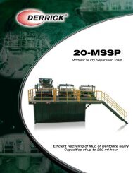
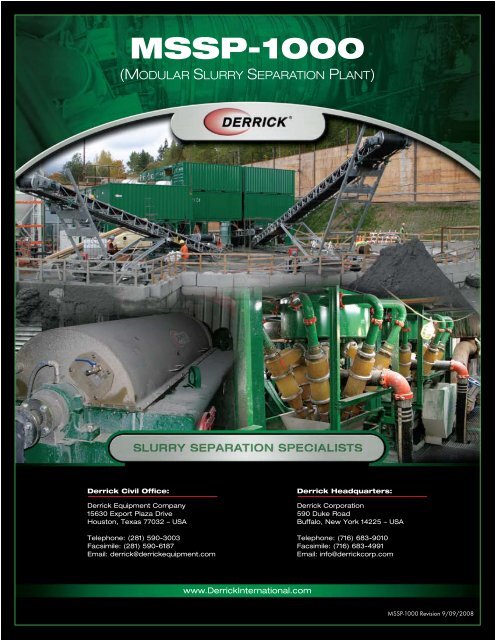
<strong>MSSP</strong>-<strong>1000</strong><br />
(MODULAR SLURRY SEPARATION PLANT)<br />
Derrick Civil Office:<br />
Derrick <strong>Equipment</strong> <strong>Company</strong><br />
15630 Export Plaza Drive<br />
Houston, Texas 77032 – USA<br />
Telephone: (281) 590-3003<br />
Facsimile: (281) 590-6187<br />
Email: derrick@derrickequipment.com<br />
www.DerrickInternational.com<br />
Derrick Headquarters:<br />
Derrick Corporation<br />
590 Duke Road<br />
Buffalo, New York 14225 – USA<br />
Telephone: (716) 683-9010<br />
Facsimile: (716) 683-4991<br />
Email: info@derrickcorp.com<br />
<strong>MSSP</strong>-<strong>1000</strong> Revision 9/09/2008
TABLE OF CONTENTS<br />
<strong>MSSP</strong>-<strong>1000</strong><br />
Overview Page 2<br />
Process Flow Page 3<br />
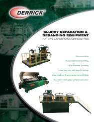
System Advantages<br />
Visual Monitoring Page 4.1<br />
System Control Page 4.1<br />
Self-Cleaning Sumps Page 4.1<br />
Plant Flexibility Page 4.1<br />
Large Capacity Page 4.1<br />
Screen Deck Angle Adjustment Page 4.2<br />
Elevated Centrifuge Page 4.2<br />
Automatic Operation Page 5<br />
Options Page 6<br />
Specification Page 7.1 - 7.4<br />
Photo Gallery Page 8 - 12<br />
Plant Modeling View Page 13 - 15<br />
Derrick <strong>Equipment</strong> <strong>Company</strong> – Modular Slurry Separation Plant<br />
1
OVERVIEW<br />
<strong>MSSP</strong>-<strong>1000</strong><br />
The Derrick Slurry Treatment Plant can process more than <strong>1000</strong> M3/Hr of fluid containing bentonite and<br />
solids excavated from tunnel boring machine (TBM) operations. The plant utilizes multiple processing steps,<br />
each designed to remove successively smaller solids. Critical steps within the process provide solids removal<br />
capacities equal to the maximum tunneling rate of the TBM. During ring-building operations, the re-circulating<br />
capability of the plant permits it to respond to challenging and constantly changing soil formations.<br />
Derrick <strong>Equipment</strong> <strong>Company</strong> – Modular Slurry Separation Plant<br />
2
PROCESS FLOW<br />
<strong>MSSP</strong>-<strong>1000</strong><br />
Flow from the TBM passes through a flowmeter and then to a Derrick C-56 low-speed, high-amplitude<br />
screening machine. The machine’s weir-style feeder distributes the slurry evenly on its urethane screen panels.<br />
Oversized material that does not pass through the screen bed is directed to a conveyor and stacker for<br />
deposit in a holding area. Solids and fluid that pass through the screen are directed by gravity to Sump 1 of<br />
the base tank, which is located directly below the screening machine.<br />
One abrasion-resistant pump draws slurry from the bottom of Sump 1 to feed 4 12” sand separator-type<br />
hydrocyclones. Each hydrocyclone discharges oversized material onto the urethane screening panels of<br />
a Derrick FLC-2000 screening machine. Undersize material and overflow fluid passing out the top of the<br />
hydrocyclones is discharged into Sump 2. Oversized material from each of the FLC-2000s is discharged<br />
to the belt conveyor. Fluid and solids that pass through the screens flow by gravity to Sump 2 for further<br />
processing.<br />
Two additional abrasion-resistant pumps have the capacity of drawing slurry from either the bottom of Sump<br />
1 to feed 8 additional 12” hydrocyclones or from Sump 2 to feed 80 4” hydrocyclones. Oversized material<br />
discharged from either the 12” sand separators or 4” hydrocyclones is further dried on 4 FLC-2000 screening<br />
machines. Overflow from the top of the hydrocyclones is fed by gravity to the appropriate sump.<br />
The three sumps in the base tank are separated by weirs for safe, gravity-flow operation. When the TBM is<br />
operating at 100 percent capacity, fluid passes through the processing equipment and then to the base tank<br />
sumps in sequential order. When the level in Sump 3 rises to the weir outlet, cleaned fluid flows by gravity to<br />
the TBM working tank. If the TBM pump is delivering less than 100 percent of design flow, part of the slurry<br />
in Sump 2 flows over the weir into Sump 1 instead of flowing out to the TBM tank. In addition, part of the<br />
slurry in Sump 3 returns to Sump 2 instead of flowing out to the TBM tank. This feature maintains sufficient<br />
fluid supply to the hydrocyclone feed pumps at all times.<br />
The plant includes two Derrick DE-7200 decanter-type centrifuges, which receive slurry from either the active<br />
working system or waste mud tank. Oversized material from the centrifuges is directed to the conveyor, while<br />
cleaned fluid flows by gravity to the TBM tank or to a site discharge point. When a nearly clear effluent<br />
discharge is desired, a completely automated dry polymer metering and mixing system can supply flocculent<br />
to both DE-7200 centrifuges simultaneously.<br />
Derrick <strong>Equipment</strong> <strong>Company</strong> – Modular Slurry Separation Plant<br />
3
SYSTEM ADVANTAGES<br />
<strong>MSSP</strong>-<strong>1000</strong><br />
Visual Monitoring<br />
Several movable and stationary cameras allow visual monitoring of all critical operations from the control<br />
room. Vision system control from a dedicated PC allows remote pan-tilt-zoom operation for the movable<br />
cameras and zoom operation for the stationary cameras.<br />
System Control<br />
System operating mode is selectable from the operator control room. Operating features in manual and<br />
automatic mode are as follows:<br />
• Manual Mode - Allows the operator to start and stop each pump and screening machine<br />
individually<br />
• Automatic Mode - Monitors the flow meter and tank level sensor feedback signals to open/<br />
close valves and successively start screening machines and pumps when flow is detected<br />
In manual or automatic mode, the operator can initiate recirculation where fluid from the TBM working tank is<br />
pumped back to Sump 2 for re-processing through the 12” or 4” hydrocyclones. This process eliminates the<br />
need to run TBM pumps for extended periods of time in bypass mode during ring-building operations, while<br />
allowing continued uninterrupted solids removal from the active working system.<br />
Self-Cleaning Sumps<br />
Sumps 1, 2 and 3 are self-cleaning during operation, eliminating the need for agitators. Each of the sumps<br />
is connected to a common pump to facilitate clean-out or draining prior to extended shutdown periods. The<br />
pump discharge can be directed to the TBM working tank or a collection tank for future processing.<br />
Plant Flexibility<br />
In soil formations consisting primarily of sand-sized particles, the 12” hydrocyclones with built-in excess<br />
processing capacity, provide exceptional solids removal. However, in soil formations containing silt-sized<br />
particles, 4 banks of 4” hydrocyclones can be employed both in drilling mode and re-circulating mode to<br />
reduce fine-sized solids accumulation in the active working system.<br />
Large Capacity<br />
Generous TBM and waste mud tank storage capacities are provided to permit operational flexibility and<br />
eliminate the need for additional off-site processing.<br />
Derrick <strong>Equipment</strong> <strong>Company</strong> – Modular Slurry Separation Plant<br />
(continues next page)<br />
4.1
<strong>MSSP</strong>-<strong>1000</strong><br />
SYSTEM ADVANTAGES (continued)<br />
Screen Deck Angle Adjustment<br />
The C-56 and all FLC-2000s have deck angle adjustment capability. Raising the deck angle increases the<br />
dryness of discharged solids but increases conveyance time. Lowering the deck angle reduces conveyance<br />
time but increases wetness.<br />
Elevated Centrifuge<br />
Remote monitoring and control permits the centrifuge to be located on the uppermost level, thereby eliminating<br />
the need for additional mechanical pumping. With the centrifuge elevated, centrifuge effluent returns by<br />
gravity to the TBM working tank or collection point for offsite discharge.<br />
Derrick <strong>Equipment</strong> <strong>Company</strong> – Modular Slurry Separation Plant<br />
4.2
AUTOMATIC OPERATION<br />
<strong>MSSP</strong>-<strong>1000</strong><br />
Fresh bentonite slurry can be mixed manually or automatically. Two operator inputs are required for automatic<br />
bentonite mixing:<br />
• Volume of new slurry to be mixed<br />
• Ratio of dry bentonite to fresh water<br />
With these inputs supplied, the control system opens the necessary valves, starts the mixing hopper pump,<br />
determines speed, and sends a start command to the bentonite silo auger to discharge the appropriate<br />
quantity of dry bentonite for the requested mix ratio.<br />
Transfer of new bentonite slurry to the active working system as well as transfer of slurry from the TBM tank to<br />
waste mud tank, can be accomplished with automatic operation. The operator is required to only define the<br />
volume of fluid to be transferred, origin tank, and destination tank. The control system opens and closes the<br />
required valves, starts the appropriate pump and monitors the destination tank level sensor when the specified<br />
volume has been transferred the pump is stopped and valves returned to their normal position.<br />
Derrick <strong>Equipment</strong> <strong>Company</strong> – Modular Slurry Separation Plant<br />
5
OPTIONS<br />
<strong>MSSP</strong>-<strong>1000</strong><br />
• Fresh water storage tank, pressure tank, pump, valves and level sensor for locations where<br />
local supply pressure or volume are insufficient.<br />
• Main power switch-panel providing electrical disconnect and protection for power supplied<br />
from sub-station to slurry plant.<br />
• DE-7200 high speed decanting centrifuge, feed pump, chute and associated valves<br />
and piping.<br />
Derrick <strong>Equipment</strong> <strong>Company</strong> – Modular Slurry Separation Plant<br />
6
SPECIFICATION<br />
<strong>MSSP</strong>-<strong>1000</strong><br />
<strong>Equipment</strong> Description: <strong>1000</strong> M 3 /Hr Separation Plant<br />
Application: Modular Slurry Treatment Plant for Large Diameter Tunneling<br />
System Capacity: <strong>1000</strong> M 3 /Hr (4,400 GPM) Fluid Volume and<br />
250 TPH Solids Removal<br />
Plant Type: Modular 20’ and 40’ Containers Stacked Three High by Two Deep.<br />
Incorporates Primary Screening, Sand Separators, Hydrocyclones,<br />
Drying Screens, Sumps, Pumps, Centrifuges, Polymer Mixing and<br />
Dispensing unit, Stairs, Walkways, Electrical Motor Control Centers,<br />
Slurry Test Lab and Control Room.<br />
Primary Screens: One C-56 Low Speed High Amplitude Screens<br />
• Capacity: 1300 M 3 /Hr (5,700 GPM)<br />
• Screen Size: 700um to 10.0mm (25 mesh to 3/8’’)<br />
• Screen Type: Derrick Patented High Open Area,<br />
Long Life Polyurethane<br />
• Dimensions: Nominal 5 feet (1.5m) wide by 14 feet (4.2m) long<br />
Sand Separators: Twelve 12” Hydrocyclones with Integrated Underflow Regulator<br />
• Capacity: 1300 M 3 /Hr (5,700 GPM)<br />
• D50 Cut Point: 35 – 55 Micron (Water-Solid Slurry with 1.3 S.G.)<br />
Hydrocyclones: Eighty 4” Urethane Construction with Ceramic Lining<br />
• Capacity: 100 M 3 /Hr (4,800 GPM)<br />
• D50 Cut Point: 15 - 40 Micron (Water-Solid Slurry with 1.3 S.G.)<br />
Cone Pumps: Three 8 X 6 X 14 Centrifugal Pump, Abrasion Resistant Wetted Parts<br />
with Mechanical Seal and VFD Control<br />
Derrick <strong>Equipment</strong> <strong>Company</strong> – Modular Slurry Separation Plant<br />
(continues next page)<br />
7.1
SPECIFICATION<br />
<strong>MSSP</strong>-<strong>1000</strong><br />
Drying Screens: Six FLC-2000 4-Panel High “G” Shakers with Adjustable Deck Angle<br />
•Capacity: Fluid - 1350 M 3 /Hr (6,000 GPM)<br />
Solid - 270 TPH (Short)<br />
• Screen Size: 500μm to 700μm (25-35 mesh)<br />
• Screen Type: Derrick Patented High Open Area,<br />
Long Life Polyurethane<br />
• Dimensions: Nominal 4 feet (1.2m) wide by 10 feet (3.0m) long<br />
Centrifuges: Two DE-7200 VFD Centrifuges with Local and Remote PLC Control<br />
• Capacity: 200 M 3 /Hr (900 GPM)<br />
• D50 Cut Point: 8-10 Micron<br />
• Conveyor Type: Helical/Radial<br />
• Bowl Diameter: 21.5’’<br />
• Bowl Length: 72’’<br />
• Gear Box Ratio: 49:1<br />
Feed Pumps: Two Progressing Cavity Centrifuge Feed Pumps<br />
• Type: Positive Displacement<br />
• Capacity: 0 - 250 M 3 /Hr (0 - 1,100 GPM)<br />
• Gear Box: Fixed Ratio<br />
• Motor: Inverter Duty<br />
Flocc Station: One Polymer Mixing and Dispensing System with<br />
Local and Remote PLC Control<br />
• Polymer Type: Dry Powder – Big Bag Package<br />
• Capacity: 460 – 4,600 l/hr (2 – 18 GPM) Metered to Two (2)<br />
Centrifuges Maximum Simultaneously via onboard<br />
Dosing Pumps<br />
Storage Tanks: Circular Large Capacity Tanks with Pipe Connection Flanges, Pipe<br />
Supports, External Caged Ladder and Observation Platform<br />
and Agitators<br />
• Type: Galvanized Steel Panel and Ring Bolted together on-site<br />
• Sizes: Two (2) 300 M 3 (80,000 Gal) TBM Active Working Tanks<br />
One (1) 900 M 3 (240,000 Gal) Waste Mud Storage Tank<br />
One (1) 200 M 3 (53,000 Gal) New Bentonite Storage Tank<br />
Derrick <strong>Equipment</strong> <strong>Company</strong> – Modular Slurry Separation Plant<br />
(continues next page)<br />
7.2
SPECIFICATION<br />
<strong>MSSP</strong>-<strong>1000</strong><br />
Bentonite Storage: One Dry Bentonite Storage Silo with Dust Control Filtering System,<br />
Level / Mass Sensing, External Caged Ladder and Observation Platform,<br />
Fill Pipe and Inclined Auger for Dispensing<br />
• Capacity: 700 BBL Dry Powder<br />
• Auger: 0 – 23 TPH VFD Controlled<br />
Bentonite Mixing: One Open Hopper with Attached Jet-Venturi Nozzle and Pump<br />
Transfer Pumps: Two 8 X 6 X 14<br />
Sump Cleanout Pumps: One 6 X 5 X 14<br />
• Capacity: Bentonite – 180 Kg per Min (400 LBS Per Minute)<br />
Fluid – 136 M3 Per Hr (600 GPM)<br />
Flow Meters: One 12” Full Flow Electromagnetic<br />
Level Sensors: Four Non-Contact Ultra-Sonic Type<br />
Conveyors: One 60 ft Horizontal Belt Conveyor with Edge Guides and Material<br />
Weighing System<br />
One 80 ft. Radial Inclined Belt Conveyor Stacker<br />
Motor Control Center: One Self Contained Climate Controlled Electrical <strong>Equipment</strong> Room<br />
containing Disconnects, Starters, Soft Starters and Variable Frequency<br />
Drives for respective Motors as well as PLC Controllers, I/O Modules,<br />
Power Supplies, Centrifuge Control Systems and Network<br />
Communication Hardware<br />
Operator Control Room: One Climate Controlled Room with Touch Screen Operator Interface<br />
Panels for Monitoring and Control of all Shakers, Centrifuges,<br />
Pumps, Agitators, Automatic Valves and Bentonite Mixing System.<br />
Derrick <strong>Equipment</strong> <strong>Company</strong> – Modular Slurry Separation Plant<br />
(continues next page)<br />
7.3
SPECIFICATION<br />
<strong>MSSP</strong>-<strong>1000</strong><br />
Slurry Test Lab: One Climate Controlled Room with Sink and Heavy Duty Floor / Wall<br />
Mount storage cabinets. Test Lab layout accommodates Bentonite<br />
Slurry testing, equipment storage and sample storage<br />
Vision System: One Plant wide Vision System consisting of multiple Pan-Tilt-Zoom<br />
cameras, multiple Zoom-Only cameras and Workstation for<br />
Monitoring and Control<br />
Valves: Three 4” Automatic Butterfly Valves<br />
Thirtythree 6” Automatic Knifegate Valves<br />
Nine 8” Manual Knifegate Valves<br />
Eight 8” Automatic Knifegate Valves<br />
Piping: All Pipes, Fittings and Connections within the Modular Structure for<br />
Pumps, Hydrocyclones and Centrifuges<br />
Elec. Cable: All Power, Control and Communication Cable within the Modular<br />
Structure necessary for <strong>Equipment</strong> Operation and Control<br />
Derrick <strong>Equipment</strong> <strong>Company</strong> – Modular Slurry Separation Plant<br />
7.4
PHOTO GALLERY<br />
Operator Control Room<br />
Motor Control Room<br />
<strong>MSSP</strong>-<strong>1000</strong><br />
Derrick <strong>Equipment</strong> <strong>Company</strong> – Modular Slurry Separation Plant<br />
8
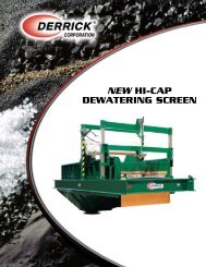
PHOTO GALLERY<br />
C56 Dewatering Machine (Recovered Solids)<br />
<strong>MSSP</strong>-<strong>1000</strong><br />
Derrick Abrasion Resistant, High Open Area Urethane Screens<br />
Derrick <strong>Equipment</strong> <strong>Company</strong> – Modular Slurry Separation Plant<br />
9
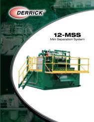
PHOTO GALLERY<br />
FLC 2000 4-Panel with Hydrocyclones<br />
Hydrocyclones Discharge<br />
<strong>MSSP</strong>-<strong>1000</strong><br />
Derrick <strong>Equipment</strong> <strong>Company</strong> – Modular Slurry Separation Plant<br />
10
PHOTO GALLERY<br />
FLC 2000 4-Panel (Discharge)<br />
C56 and FLC 2000 (Discharge Pile)<br />
<strong>MSSP</strong>-<strong>1000</strong><br />
Derrick <strong>Equipment</strong> <strong>Company</strong> – Modular Slurry Separation Plant<br />
11
PHOTO GALLERY<br />
DE-7200 VFD Centrifuge<br />
DE-7200 Centrifuge (Discharge)<br />
<strong>MSSP</strong>-<strong>1000</strong><br />
Derrick <strong>Equipment</strong> <strong>Company</strong> – Modular Slurry Separation Plant<br />
12
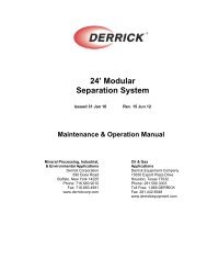
PLANT MODELING VIEW<br />
<strong>MSSP</strong> - <strong>1000</strong> ISO Front View<br />
<strong>MSSP</strong>-<strong>1000</strong><br />
Derrick <strong>Equipment</strong> <strong>Company</strong> – Modular Slurry Separation Plant<br />
13
PLANT MODELING VIEW<br />
<strong>MSSP</strong> - <strong>1000</strong> ISO Back View<br />
<strong>MSSP</strong>-<strong>1000</strong><br />
Derrick <strong>Equipment</strong> <strong>Company</strong> – Modular Slurry Separation Plant<br />
14
PLANT MODELING VIEW<br />
<strong>MSSP</strong> - <strong>1000</strong> ISO Side View<br />
<strong>MSSP</strong>-<strong>1000</strong><br />
Derrick <strong>Equipment</strong> <strong>Company</strong> – Modular Slurry Separation Plant<br />
15