XM-800 Part Numbers - Pressure Switch Instruments - Gems Sensors
XM-800 Part Numbers - Pressure Switch Instruments - Gems Sensors
XM-800 Part Numbers - Pressure Switch Instruments - Gems Sensors

You also want an ePaper? Increase the reach of your titles
YUMPU automatically turns print PDFs into web optimized ePapers that Google loves.
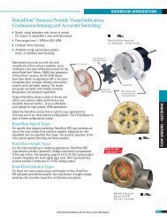
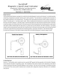
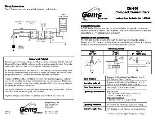
Wiring Connections<br />
<strong>Gems</strong> Transmitters interface with intrinsically safe barriers.<br />
Hazardous<br />
Area<br />
BLK<br />
RED<br />
WHT<br />
<strong>Gems</strong><br />
<strong>XM</strong>-<strong>800</strong><br />
Non-Hazardous<br />
Area<br />
Full Ref<br />
<strong>Switch</strong><br />
Zener Barrier<br />
SAFE-PAK<br />
<strong>Gems</strong><br />
TLI Receiver<br />
Important Points!<br />
Product must be maintained and installed in strict accordance with the National<br />
Electrical Code and GEMS technical brochure and instruction bulletin. Failure to<br />
observe this warning could result in serious injuries or damages.<br />
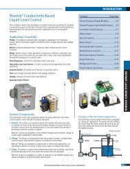
General Information<br />
GEMS <strong>XM</strong>-<strong>800</strong> Series provides an output suitable for use with our analog<br />
receiver stations or Level Cube receivers. The units mount internally and are<br />
accurate to ± 1/4”, regardless of tank depth<br />
Installation and Maintenance<br />
The <strong>XM</strong>-<strong>800</strong> may be installed through the tank top with mounting plug or<br />
flange, up to 30° vertical. Maintenance requirements are minimal and usually<br />
limited to occasional removal of accumulated scum or scale.<br />
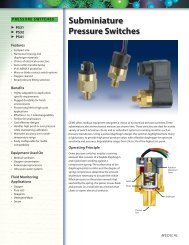
à<br />
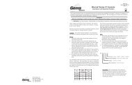
1-1/4"<br />
à<br />
Type 1<br />
1/2" NPT<br />
3/4"<br />
FLHTS<br />
- Mounting Types -<br />
à<br />
2-3/4"<br />
à<br />
<strong>XM</strong>-<strong>800</strong><br />
Compact Transmitters<br />
Instruction Bulletin No. 140894<br />
Type 3<br />
2" NPT<br />
1/2"<br />
NPT<br />
1-1/4"<br />
1/2"<br />
NPT<br />
Type 4<br />
3" - 150# Flange<br />
à<br />
2-1/4"<br />
à<br />
An appropriate explosion-proof enclosure or intrinsically safe interface device must<br />
be used for hazardous area applications involving such things as (but not limited<br />
to) ignitable mixtures, combustible dust and flammable materials.<br />
<strong>Pressure</strong> and temperature limitations shown on individual catalog pages and drawings<br />
for the specified liquid level transmitters must not be exceeded. These pressures<br />
and temperatures take into consideration possible system surge pressures/<br />
temperatures and their frequencies.<br />
The liquids used must be compatible with the materials of construction. Specifications<br />
of materials will be given upon request.<br />
Physical damage sustained by the product may render it unserviceable.<br />
140894<br />
Rev. B<br />
Stem Material<br />
Mounting Material<br />
Float Stop Material<br />
Operating Temperature*<br />
Operating <strong>Pressure</strong><br />
Overall Length, Max.<br />
Brass or 316 Stainless Steel (Types 1 and 3)<br />
316 Stainless Steel (Type 4)<br />
Brass or 316 Stainless Steel (Types 1 and 3)<br />
Carbon or 316 Stainless Steel (Type 4)<br />
Grip Rings (18-8 Stainless Steel)<br />
Buna N Float<br />
Oil: -40°F to +230°F (-40°C to 110°C)<br />
Water: to +180°F (82.2°C)<br />
Stainless Steel Float<br />
-40°F to +230°F (-40°C to 110°C)<br />
Dependent on Float Type (See Next Page)<br />
70" (Please consult Factory for longer lengths)<br />
* Consult Factory for Higher Temperature Ranges
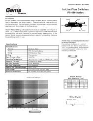
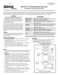
Typical Dimensions<br />
Float Types<br />
1/2" NPT<br />
Float Material<br />
Buna N<br />
Stainless Steel<br />
1-1/4"<br />
à<br />
à<br />
Float Dimensions<br />
1-13/16"<br />
Typ.<br />
2-3/4"<br />
Typ.<br />
à<br />
à à<br />
C<br />
à<br />
A<br />
à<br />
à<br />
D<br />
à<br />
Indicating<br />
Length<br />
Highest<br />
Level<br />
Indicated<br />
<strong>Part</strong> Number<br />
à<br />
à 1-7/8"<br />
Dia. Typ.<br />
43359<br />
à<br />
à<br />
à 2-1/16"<br />
Dia. Typ.<br />
43590<br />
à<br />
B<br />
à<br />
E<br />
à<br />
Lowest<br />
Level<br />
Indicated<br />
Min. Liquid Specific Gravity<br />
Operating <strong>Pressure</strong>, Max.<br />
.55<br />
150 PSI<br />
.75<br />
300 PSI<br />
à<br />
à<br />
Dimensions<br />
A: Float Travel = Indicating Length +3/8"<br />
B: Overall Length<br />
- With Buna N Float: Indicating Length + 2-1/2" + C<br />
- With Stainless Steel Float: Indicating Length + 3-7/16" + C<br />
Input / Output<br />
For <strong>XM</strong>-<strong>800</strong> Series, no special output designation is necessary.<br />
Electrical<br />
Input Voltage<br />
Output Signal<br />
Termination<br />
C: Distance to Float Stop (Specified by Customer): 1/4", Min.<br />
D: With Buna N Float: 1-3/16"<br />
With Stainless Steel Float: 1-9/16"<br />
10 to 30 VDC<br />
Proportional Voltage<br />
Lead Wires (3),<br />
#22 AWG, 24"<br />
Teflon® Jacket<br />
E: With Buna N Float: 1-5/16"<br />
With Stainless Steel Float: 1-3/4"<br />
Notes<br />
1. Distances for highest and lowest level indicated are based on<br />
use in liquid of 1.0 and are approximate values.<br />
2. Indicating length must be specified in even increments<br />
of 1/2".