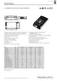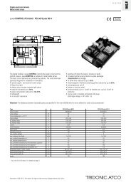
powerCONTROL PCI A001/2, PCS A001
powerCONTROL PCI A001/2, PCS A001
powerCONTROL PCI A001/2, PCS A001

You also want an ePaper? Increase the reach of your titles
YUMPU automatically turns print PDFs into web optimized ePapers that Google loves.
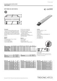
Digital electronic ballasts<br />
High pressure discharge lamps<br />
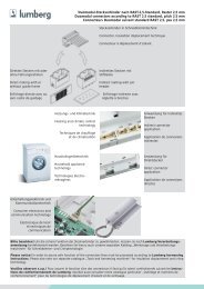
Installation instructions<br />
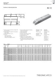
Wiring type and cross section<br />
Stranded wire with end ferrule or solid wire with<br />
a cross section between 0.5 and 2.5 mm 2 may be<br />
used for wiring. Strip 7 mm of insulation from the<br />
cables to ensure perfect operation of the screw<br />
terminals.<br />
wire preparation:<br />
0.5 – 2.5<br />
7 mm<br />
Important advise<br />
When a lamp is changed (at the end of its life),<br />
if a lamp is missing or after overtemperature<br />
shutdown the mains voltage of the ECG must<br />
be disconnected.<br />
Warning – starting voltage up to<br />
max. 3 or 5 kV!<br />
Not suitable for use with lamps with<br />
integral ignitors.<br />
Note on wiring<br />
The length of the lamp wires is limited by the<br />
value of cable capacitance.<br />
In class 1 luminaires it is necessary to earth the<br />
ballast and the luminaire via the earth terminal,<br />
in class 2 luminaires not.<br />
To avoid the damage of the control gear, the wiring<br />
must be protected against short circuits to earth<br />
(sharp edged metal parts, metal cable clips, louver,<br />
etc.).<br />
Lamp re-ignition / A002<br />
The time required by a high pressure lamp to warm<br />
up or re-ignite is bridged by an additional lamp.<br />
A relay switches the mains phase internally and an<br />
additional lamp of up to max. 500 W (incandescent<br />
lamps) or 200 VA (inductive load) can be connected.<br />
The maximum output can be divided over<br />
several light points.<br />
The additional lamp will also be switched on if<br />
there is no lamp on the ballast.<br />
DC-input is not suitable.<br />
Safety switch off<br />
End of life of the lamps<br />
At the end of their useful life, lamps often cycle on/<br />
off. The <strong>PCI</strong> ballast recognises this condition<br />
and switches off the lamp, after three complete on/<br />
off cycles and whilst the supply has been<br />
unswitched. Complete lamp switch off enables<br />
easy identification of a defective lamp in the<br />
application. After a change of the faulty lamp and<br />
an interruption of the mains supply (mains reset)<br />
the ballast will strike the lamp. When there is no<br />
lamp in circuit or a defective lamp is connected to<br />
the ballast, the ballast will switch off after apr. 25<br />
minutes (3.5 minutes of ignition time).<br />
Overtemperature shutdown<br />
The units shut down at Dt approx. +10 °C<br />
compared with tc/ta. A mains reset must be<br />
carried out so that the units switch on again.<br />
Overload strength<br />
320 V AC / 1 h<br />
Standards<br />
EN 55015 (radio interference)<br />
EN 61000-3-2 (mains harmonics)<br />
EN 61347-2-12<br />
EN 61547 (interference immunity)<br />
CE mark<br />
EMV VDE mark<br />
ENEC or VDE mark<br />
Radio interference<br />
• Do not cross mains and lamp cables.<br />
• Do not lay mains cables together with lamp<br />
cables (ideally they should be 5–10 cm apart).<br />
• Do not lead mains cables too closely along the<br />
electronic ballast.<br />
• Twist lamp cables.<br />
• Increase the distance between lamp cables and<br />
earthed metal surfaces.<br />
• Keep the mains cable in the luminaire short.<br />
If several ballasts are installed in masts, boxes,<br />
etc., measures must be taken to avoid overheating<br />
of individual components.<br />
Packing quantities<br />
10 pieces/box<br />
60 boxes/pallet<br />
600 pieces/pallet<br />
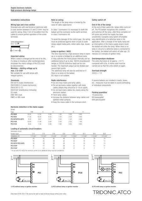
Harmonic distortion in the mains supply<br />
Ballast<br />
Type THD 3 5 7 9 11<br />
<strong>PCI</strong> 0020 14.50 12.50 5.50 1.00 2.00 0.60<br />
<strong>PCI</strong> 0035 17.30 16.05 6.55 1.05 2.04 0.80<br />
<strong>PCI</strong> 0070/<strong>PCS</strong> 0070 9.20 9.67 3.71 2.02 1.50 0.88<br />
<strong>PCI</strong> 0100 13.00 11.00 5.00 2.00 2.50 1.00<br />
<strong>PCI</strong> 0150 9.50 7.45 3.30 1.80 2.00 0.80<br />
Loading of automatic circuit breakers<br />
Automatic circuit<br />
breaker type C10 C13 C16 C20 B10 B13 B16 B20<br />
Installation ∅ 1.5 mm 2 1.5 mm 2 1.5 mm 2 2.5 mm 2 1.5 mm 2 1.5 mm 2 1.5 mm 2 2.5 mm 2<br />
<strong>PCI</strong> 0020* 24 33 42 48 12 15 19 19<br />
<strong>PCI</strong> 0035* 16 22 28 32 8 10 13 13<br />
<strong>PCI</strong> 0070*/<strong>PCS</strong> 0070 10 18 26 30 6 10 13 13<br />
<strong>PCI</strong> 0100* 9 17 23 26 5 8 11 11<br />
<strong>PCI</strong> 0150* 7 14 20 20 4 6 7 7<br />
* In use with <strong>PCI</strong> A002 the nominal current of an additional lamp must be considered<br />
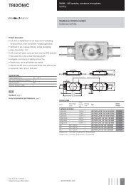
<strong>PCS</strong><br />
<strong>PCI</strong><br />
max. 2 kV<br />
max. 5 kV<br />
1) <strong>PCI</strong> without lamp re-ignition monitor 2) <strong>PCS</strong> without lamp re-ignition monitor<br />
3) <strong>PCI</strong> with lamp re-ignition monitor<br />
Data sheet 07/08-253-4 We reserve the right to make technical changes without prior notice.