Liquid Interface at Wafer Test - Semiconductor Wafer Test Workshop
Liquid Interface at Wafer Test - Semiconductor Wafer Test Workshop
Liquid Interface at Wafer Test - Semiconductor Wafer Test Workshop

You also want an ePaper? Increase the reach of your titles
YUMPU automatically turns print PDFs into web optimized ePapers that Google loves.
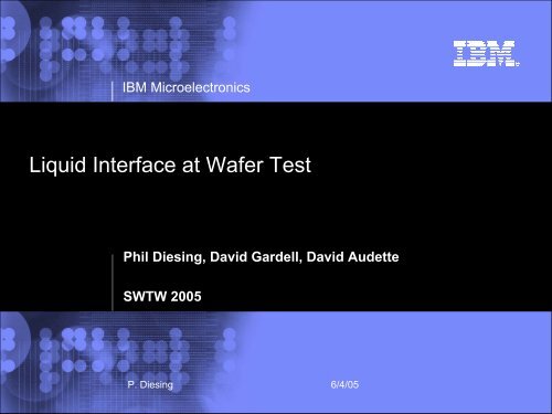
IBM Microelectronics<br />
<strong>Liquid</strong> <strong>Interface</strong> <strong>at</strong> <strong>Wafer</strong> <strong>Test</strong><br />
Phil Diesing, David Gardell, David Audette<br />
SWTW 2005<br />
P. Diesing 6/4/05
Agenda<br />
• Why liquid thermal interface?<br />
– Existing thermal problems <strong>at</strong> module test<br />
– Thermal roadmap<br />
– Predicted thermal problems <strong>at</strong> wafer test<br />
• Proposed solution<br />
• Predicted benefit from lower resistance<br />
• Results of hardware development effort<br />
1 P, Diesing 6/4/05
CHIP LEAKAGE HOTSPOTS<br />
(microprocessor logic cores)<br />
Source [2]<br />
2 P, Diesing 6/4/05
THERMAL RUNAWAY<br />
• Thermal runaway is a positive feedback phenomena in which<br />
leakage current and temper<strong>at</strong>ure interact in an exponential<br />
fashion with each other<br />
More Current<br />
More Current<br />
More Current<br />
More Current<br />
Higher Temper<strong>at</strong>ure<br />
Higher Temper<strong>at</strong>ure<br />
Higher Temper<strong>at</strong>ure<br />
Higher Temper<strong>at</strong>ure<br />
Initial IC T J<br />
Source [2]<br />
3 P, Diesing 6/4/05
THERMAL RUNAWAY<br />
•View of damaged chip from C4<br />
(solder ball) side<br />
•Failure analysis photo<br />
Source [2]<br />
4 P, Diesing 6/4/05
Thermal Problems <strong>at</strong> <strong>Wafer</strong> <strong>Test</strong><br />
• Sharply increasing power roadmap<br />
– Predicts th<strong>at</strong> module test problems will also be seen <strong>at</strong><br />
wafer test<br />
5 P, Diesing 6/4/05
Module Power Trends<br />
Module He<strong>at</strong> Flux(w<strong>at</strong>ts/cm 2 )<br />
14<br />
12<br />
10<br />
8<br />
6<br />
4<br />
2<br />
IBM ES9000<br />
Fujitsu VP2000<br />
IBM 3090S<br />
NTT<br />
Fujitsu M-780<br />
IBM 3090<br />
Start of W<strong>at</strong>er<br />
CDC Cyber 205<br />
IBM 4381<br />
Cooling<br />
IBM 3081<br />
Fujitsu M380<br />
Vacuum IBM 360 IBM 370 IBM 3033<br />
CMOS<br />
Bipolar<br />
0<br />
1950 1960 1970 1980 1990 2000 2010<br />
Year of Announcement<br />
T-Rex<br />
Mckinley<br />
Squadrons<br />
IBM GP<br />
IBM RY5<br />
IBM RY7<br />
Pentium 4<br />
Pulsar<br />
IBM RY6<br />
IBM RY4<br />
Apache<br />
Merced<br />
Pentium II(DSIP)<br />
Prescott<br />
Jayhawk(dual)<br />
Source [1]<br />
6 P, Diesing 6/4/05
Leakage Current Roadmap<br />
High Performance Microprocessor<br />
Ampere<br />
180 130 90 65 45<br />
Technology node (nm)<br />
7 P, Diesing 6/4/05
Anticip<strong>at</strong>ed Thermal Problems <strong>at</strong> <strong>Wafer</strong> <strong>Test</strong><br />
• Problems from high power levels<br />
– <strong>Wafer</strong> damage<br />
– Unknown wafer sort st<strong>at</strong>us due to incomplete test (overcurrent<br />
shutdown)<br />
– Incorrect speed sorting due to temper<strong>at</strong>ure rise and<br />
resulting speed shift<br />
– Probe card damage<br />
8 P, Diesing 6/4/05
Incomplete <strong>Wafer</strong> <strong>Test</strong>ing<br />
• High leakage parts may exceed power supply<br />
capacity<br />
• These untested parts are passed on to module<br />
test<br />
• Increased number of defective parts causes<br />
higher packaging and test costs<br />
9 P, Diesing 6/4/05
Thermal Problems <strong>at</strong> <strong>Wafer</strong> <strong>Test</strong><br />
Incorrect Speed Sorting Due to<br />
Temper<strong>at</strong>ure Rise<br />
Power vari<strong>at</strong>ions can cause a<br />
temper<strong>at</strong>ure difference gre<strong>at</strong>er than 30 C<br />
% Change in speed<br />
6<br />
5<br />
4<br />
3<br />
2<br />
1<br />
0<br />
0 10 20 30 40<br />
Max allowable<br />
speed change<br />
Temper<strong>at</strong>ure Rise (C)<br />
10 P, Diesing 6/4/05
Probe Card Damage<br />
• High currents can damage probe cards<br />
– Expensive to repair or replace<br />
– Delay in shipping tested wafers (if cards in limited supply)<br />
[5]<br />
11 P, Diesing 6/4/05
Solution<br />
• Thermal resistance improvement<br />
– This provides three benefits:<br />
• Reduces the temper<strong>at</strong>ure rise vs. power<br />
• Reduces the die to die temper<strong>at</strong>ure vari<strong>at</strong>ion (due to varying<br />
power levels)<br />
• Reduces the effect of across the chuck resistance vari<strong>at</strong>ion<br />
12 P, Diesing 6/4/05
Speed sorting benefit from reduced thermal resistance<br />
Larger power vari<strong>at</strong>ion without sort error<br />
Temper<strong>at</strong>ure Rise<br />
80<br />
70<br />
60<br />
50<br />
40<br />
30<br />
20<br />
10<br />
0<br />
0.5 C/W<br />
0.25 C/W<br />
0 50 100 150<br />
Power<br />
10 X 10 mm powered area<br />
13 P, Diesing 6/4/05
Assessing the Most Effective Approach to Reduce Thermal<br />
Resistance<br />
• First step is to quantify the contributors to thermal<br />
resistance<br />
14 P, Diesing 6/4/05
Thermal Resistance Components<br />
<strong>Wafer</strong> to chuck resistance (R0+R1) is largest contributor<br />
R0<br />
100%<br />
90%<br />
R1<br />
80%<br />
R2<br />
R3<br />
R4<br />
70%<br />
60%<br />
50%<br />
40%<br />
77.3%<br />
R0+R1<br />
R2<br />
R3+R4+R5<br />
R5<br />
R6<br />
30%<br />
20%<br />
10%<br />
0%<br />
8%<br />
14.7%<br />
R<strong>at</strong>e of thermal 1 resistance<br />
Source: Tokyo Electron<br />
15 P, Diesing 6/4/05
Improving wafer to chuck dry contact<br />
• Theoretically, resistance could be improved by<br />
increasing chuck and wafer smoothness and fl<strong>at</strong>ness<br />
• However, this resistance would be likely be sensitive<br />
to any particles or surface damage<br />
• Measurements showed th<strong>at</strong> it wasn’t possible to<br />
m<strong>at</strong>ch wafer and chuck contours<br />
• Backside polishing of 300 mm wafers gave only 5 to<br />
10% improvement and added processing cost<br />
(D<strong>at</strong>a courtesy of David Audette, IBM)<br />
16 P, Diesing 6/4/05
Chuck top Smoothness<br />
1. Overall chuck fl<strong>at</strong>ness was 2.9um across<br />
more than 300 mm. (High quality surface)<br />
2. However, localized roughness was 1.9 um<br />
(Silicon wafer is about 0.35 um)<br />
10mm<br />
2<br />
Maximum<br />
1.5<br />
3. Conclusion: it is not practical to make<br />
sufficiently smooth m<strong>at</strong>ching surfaces<br />
(chuck to wafer)<br />
Source: Tokyo Electron<br />
1.9um<br />
1<br />
0.5<br />
0<br />
-110 -100 -90 -80 -70 -60 -50 -40 -30 -20 -10 0 10 20 30 40 50 60 70 80 90 100 110<br />
-0.5<br />
-1<br />
-1.5<br />
17 P, Diesing 6/4/05<br />
-2
Thermal Resistance Options<br />
• <strong>Interface</strong> Gas<br />
– Helium would give some improvement but not enough<br />
(approxim<strong>at</strong>ely 20%)<br />
18 P, Diesing 6/4/05
Thermal Resistance Benefit from Wet <strong>Interface</strong><br />
• Main resistance is <strong>at</strong> interface of wafer to chuck<br />
• Fluid replaces air in microscopic gaps<br />
• Note th<strong>at</strong> the he<strong>at</strong> is not carried away by fluid flow;<br />
it is conducted through the fluid into the chuck<br />
• Thermal uniformity is less sensitive to surface<br />
finish or particles, since fluid fills any gaps.<br />
19 P, Diesing 6/4/05
<strong>Liquid</strong> <strong>Interface</strong> Chuck System<br />
• Goal : achieve the minimum thermal resistance and<br />
maximum thermal uniformity.<br />
• At least 600 W capability<br />
• Approach must be consistent with the following guidelines<br />
– Avoid radical change to the tool<br />
• Avoid large development costs, and reduce lead time<br />
• Upgrade must be retrofittable to minimize the cost<br />
– Minimize additional processing cost<br />
– Dry or wet mode oper<strong>at</strong>ion (same prober, with minimal<br />
transition time)<br />
– 200 and 300 mm<br />
20 P, Diesing 6/4/05
Concept<br />
a) The wafer is pulled tightly onto the dry chuck by vacuum.<br />
b) Fluid is supplied under pressure on the supply side and pulled by<br />
vacuum <strong>at</strong> the recovery side.<br />
c) The fluid seeps between the supply and recovery sides via the<br />
wafer / chuck interface.<br />
<strong>Wafer</strong><br />
Vacuum<br />
Fluid<br />
Chuck top<br />
Source: Tokyo Electron<br />
21 P, Diesing 6/4/05
Fluid Under Glass <strong>Wafer</strong> (Prototype Chuck)<br />
Note th<strong>at</strong> the wafer is lifted up on the pins, <strong>at</strong> which point the fluid is normally<br />
completely recovered.<br />
Source: Tokyo Electron<br />
22 P, Diesing 6/4/05
LTI <strong>Test</strong>ing Results<br />
1,21<br />
3,20<br />
0,17<br />
1,18<br />
4,15<br />
-5,15<br />
-2,15<br />
1,15<br />
7,15<br />
Thermal resistance (dC/W)<br />
0.16<br />
0.14<br />
0.12<br />
0.10<br />
0.08<br />
0.06<br />
0.04<br />
0.02<br />
0.00<br />
1,15<br />
7,15<br />
3,20<br />
1,21<br />
Wet<br />
Wet<br />
-5,15<br />
1,8<br />
-2,15<br />
1,18<br />
4,15<br />
0,17<br />
1,8<br />
Die loc<strong>at</strong>ion<br />
0.13 C/W (Avg)<br />
Front<br />
Die Loc<strong>at</strong>ion<br />
Source: Tokyo Electron<br />
23 P, Diesing 6/4/05
Thermal Resistance vs. Die size<br />
Experimental d<strong>at</strong>a<br />
Current chuck<br />
0.7<br />
0.6<br />
8*8mm<br />
Thermal resistance (dC/W)<br />
0.5<br />
0.4<br />
0.3<br />
0.2<br />
0.1<br />
Dry Chuck<br />
20*20mm<br />
Wet Chuck<br />
20*40mm<br />
0<br />
0 100 200 300 400 500 600 700 800<br />
Area (mm2)<br />
Source: Tokyo Electron<br />
24 P, Diesing 6/4/05
Installed System<br />
Circul<strong>at</strong>or for liquid interface with TEL P12XLn and Teradyne J973<br />
25 P, Diesing 6/4/05
Current St<strong>at</strong>us<br />
• System meets all specific<strong>at</strong>ions<br />
– Reduces thermal resistance by 50%<br />
– Uniformity is better by 70 %<br />
– Maintains performance <strong>at</strong> 600 W or more<br />
• <strong>Liquid</strong> thermal interface system has been installed and has<br />
run engineering wafers<br />
– Wet vs. dry oper<strong>at</strong>ion is transparent to oper<strong>at</strong>ors (part of<br />
product file)<br />
– No wafer handling issues<br />
26 P, Diesing 6/4/05
Predicted Benefit<br />
This chuck will be an essential tool for<br />
– Preventing thermal runaway<br />
– Improving speed sorting accuracy<br />
– Reducing probe card damage<br />
27 P, Diesing 6/4/05
ACKNOWLEDGEMENTS<br />
This liquid interface system was a joint<br />
development project between IBM and Tokyo<br />
Electron<br />
Principal Contributors<br />
– IBM: Phil Diesing, David Audette, David Gardell<br />
– TEL: Yutaka Akaike, Glen Lansman, Shane Pudvah,<br />
Yoshinao Kono<br />
28 P, Diesing 6/4/05
References:<br />
1. New York D<strong>at</strong>a Center Facilities and Engineering, Conference /<br />
Expo 2005. Roger Schmidt, IBM<br />
2. IC Power: the Influence and Impact of <strong>Semiconductor</strong> Technology.<br />
Marc Knox, IBM Microelectronics, BiTS 2004<br />
3. Dean Percy, IBM Microelectronics<br />
4. Steven Duda, IBM Microelectronics<br />
29 P, Diesing 6/4/05