ISMI Probe Council - Semiconductor Wafer Test Workshop
ISMI Probe Council - Semiconductor Wafer Test Workshop
ISMI Probe Council - Semiconductor Wafer Test Workshop

Create successful ePaper yourself
Turn your PDF publications into a flip-book with our unique Google optimized e-Paper software.
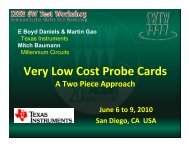
June 7-10, 2009<br />
San Diego, CA<br />
<strong>ISMI</strong> <strong>Probe</strong> <strong>Council</strong><br />
Current Carrying Capability Measurement Standard<br />
E Boyd Daniels<br />
<strong>Probe</strong> <strong>Council</strong> Chairman<br />
Texas Instruments
Overview<br />
• Introduction<br />
• Scope<br />
• Measurement Conditions<br />
• Setup<br />
• Method<br />
• Summary<br />
June 7 to 10, 2009<br />
IEEE SW <strong>Test</strong> <strong>Workshop</strong> 2
Introduction<br />
• The measurement of current carrying capability<br />
(CCC) for wafer probes is a critical parameter<br />
for probe cards in production.<br />
• Failure of a probe subjected to high current is a<br />
thermal event. Heat transferred through the<br />
mounting and contact of the probe to the pad or<br />
bump drives significant variation in the CCC.<br />
• The goal of this guideline is<br />
to minimize variability in the<br />
measurement of this critical<br />
parameter.<br />
June 7 to 10, 2009<br />
IEEE SW <strong>Test</strong> <strong>Workshop</strong> 3
Scope<br />
• With a focus on reproducible measurements,<br />
this guideline provides CCC ratings that are<br />
inherently different from what a user will see in<br />
a production environment.<br />
• The CCC measured for single probes with<br />
excellent electrical connections are typically<br />
higher than values seen in a large array of wires<br />
with varying contact resistance.<br />
• The factors that translate measurements made<br />
using this guideline into ratings for any<br />
particular production application will be unique.<br />
June 7 to 10, 2009<br />
IEEE SW <strong>Test</strong> <strong>Workshop</strong> 4
Scope<br />
• By focusing on a reproducible technique, the<br />
guideline provides a comparison metric for<br />
CCC that can be used to easily rate any probe.<br />
• Accuracy relative to each unique test<br />
application is sacrificed for the sake of a<br />
repeatable and standard set of measurements.<br />
• The underlying value of this<br />
measurement standard is<br />
relative comparison between<br />
different probing technologies.<br />
June 7 to 10, 2009<br />
IEEE SW <strong>Test</strong> <strong>Workshop</strong> 5
Measurement Conditions<br />
• The fail signature chosen for the CCC value is a<br />
permanent reduction of force in the probe.<br />
• By measuring the point at which this force is<br />
reduced by 20% for nominal overdrive settings,<br />
good electrical contact is still temporarily<br />
maintained.<br />
• However, the robustness of the contact has<br />
changed dramatically and further use in<br />
production may lead to higher maintenance and<br />
eventual loss of contact.<br />
June 7 to 10, 2009<br />
IEEE SW <strong>Test</strong> <strong>Workshop</strong> 6
Measurement Conditions<br />
• Fail Definition<br />
– The 20% force reduction method is applied to the force measured for a new<br />
probe prior to exposure to current. In practice, the force of the probe at<br />
nominal overdrive actually increases as current is first applied and there is<br />
also some amount of work hardening that increases the spring constant of<br />
the wire during the initial touchdowns. The 20% force reduction does not<br />
apply to the higher force seen early on during testing.<br />
• Measurement Timing<br />
– While measurements can certainly be made in situ while current is being<br />
applied, this standard calls for the measurement to be made at least 10<br />
seconds after current has stopped. This gives the probe a chance to cool<br />
and recover and is felt to be more representative of a production<br />
environment.<br />
• Temperature<br />
– Given that the failure mode is directly<br />
caused by heat, the temperature of the<br />
testing environment will have a significant<br />
impact on the CCC. For comparison<br />
purposes, the simplest environment,<br />
ambient (23° to 25° C), was chosen.<br />
June 7 to 10, 2009<br />
IEEE SW <strong>Test</strong> <strong>Workshop</strong> 7
Measurement Conditions<br />
• Overdrive<br />
– Once again there are many<br />
recipes used by different<br />
companies for production. For<br />
this guideline, the overdrive<br />
chosen is the distance<br />
recommended by the probe<br />
vendor for production setup for<br />
the probe being tested.<br />
• Extensions<br />
– While the guideline addresses simple DC application of current on a<br />
single wire at ambient temperature, the production environment is<br />
likely quite different. Multiple wires, test at high or low temp, pulsing<br />
current supplies and different interface materials and metallurgy are<br />
just a few of the items which will cause the wire to have a different<br />
CCC during production. Any of these items and many others may<br />
lead to a de-rating of the standard CCC for most production<br />
applications.<br />
June 7 to 10, 2009<br />
IEEE SW <strong>Test</strong> <strong>Workshop</strong> 8
Setup<br />
• The setup for CCC measurement is shown in Fig 1, 2<br />
and 3. The basic system consists of a force transducer<br />
mounted on a vertical micrometer stage and a fixture<br />
that captures the probe between two conductive<br />
contacts. A constant current power supply and current<br />
and voltage meters complete the setup.<br />
June 7 to 10, 2009<br />
IEEE SW <strong>Test</strong> <strong>Workshop</strong> 9
MEMS Setup<br />
Mechanical Fixture<br />
2-Wire for<br />
CRes<br />
Measurement<br />
Keithley Current<br />
Source/Meter<br />
Load Cell<br />
Coupling<br />
Supplier Space Transformer<br />
(MLC. MLO, PCB) + <strong>Probe</strong><br />
Micrometer<br />
Rhodium Plate<br />
June 7 to 10, 2009<br />
IEEE SW <strong>Test</strong> <strong>Workshop</strong> 10
Vertical Setup<br />
Mechanical Fixture<br />
2-Wire for<br />
CRes<br />
Measurement<br />
Keithley Current<br />
Source/Meter<br />
Load Cell<br />
Coupling<br />
Supplier Space Transformer<br />
(MLC. MLO, PCB) + <strong>Probe</strong><br />
Micrometer<br />
Rhodium Plate<br />
June 7 to 10, 2009<br />
IEEE SW <strong>Test</strong> <strong>Workshop</strong> 11
Cantilever Setup<br />
Mechanical Fixture<br />
2-Wire for<br />
CRes<br />
Measurement<br />
Keithley Current<br />
Source/Meter<br />
Load Cell<br />
Coupling<br />
PCB<br />
Micrometer<br />
Rhodium Plate<br />
June 7 to 10, 2009<br />
IEEE SW <strong>Test</strong> <strong>Workshop</strong> 12
Setup<br />
Measurement of nominal overtravel<br />
• The force transducer is mounted on a micrometer table.<br />
• Ranges and resolution recommended for measurement<br />
equipment.<br />
– Force Transducer with a resolution of
Method<br />
• At nominal overtravel, DC current is applied to the<br />
probe for 2 minutes, then removed. A force<br />
measurement is taken at least 10 seconds after the<br />
current is removed. The current is then incremented<br />
and the cycle repeated until the probe spring force is<br />
reduced by 40%. The CCC rating becomes the average<br />
of all readings at which a permanent 20% force<br />
reduction is measured.<br />
June 7 to 10, 2009<br />
IEEE SW <strong>Test</strong> <strong>Workshop</strong> 14
Method<br />
• Number of Samples<br />
– The sample size will consists of 3 sets of 10 probes picked<br />
randomly from at least 3 different production batches for a total of<br />
30 probes.<br />
• Ambient temperature<br />
– The measurements are made at room temperature between 23°C<br />
and 25°C for the duration of the test.<br />
• Initial measurements<br />
– Before any significant current is applied to the probe, the spring<br />
force of the probe should be measured at nominal overdrive.<br />
June 7 to 10, 2009<br />
IEEE SW <strong>Test</strong> <strong>Workshop</strong> 15
Method<br />
• DC Current Measurements<br />
The steps for ramping and measuring the current limit<br />
are as follows:<br />
1. Determine a probable CCC fail value by referencing probe card<br />
supplier’s specification. Set current source to 75% of specified<br />
value.<br />
2. Apply current for 2 minutes and then reduce to zero.<br />
3. Measure probe force after a 10 second cool down period.<br />
4. Increment current by 25mA.<br />
5. Repeat steps 2 – 4 until the force has dropped by 40% of initial<br />
value.<br />
June 7 to 10, 2009<br />
IEEE SW <strong>Test</strong> <strong>Workshop</strong> 16
Method<br />
2.1<br />
Initial Force<br />
1.9<br />
Force -<br />
Grams<br />
1.7<br />
1.5<br />
1.3<br />
60% Force<br />
80% Force<br />
1.1<br />
0.9<br />
0.7<br />
CCC ~0.76A<br />
0.5<br />
0.3 0.4 0.5 0.6 0.7 0.8 0.9 1 1.1<br />
Current - Amp<br />
June 7 to 10, 2009<br />
IEEE SW <strong>Test</strong> <strong>Workshop</strong> 17
Acknowledgements<br />
• Jack Courtney – IBM<br />
• John Caldwell – Micron Technology<br />
• MPI – Taiwan<br />
• Tom Wear – <strong>ISMI</strong><br />
Thank you<br />
June 7 to 10, 2009<br />
IEEE SW <strong>Test</strong> <strong>Workshop</strong> 18