PhD Thesis Abstract - E-journal
PhD Thesis Abstract - E-journal
PhD Thesis Abstract - E-journal

You also want an ePaper? Increase the reach of your titles
YUMPU automatically turns print PDFs into web optimized ePapers that Google loves.
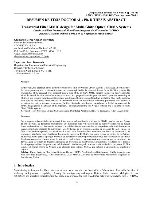
Computación y Sistemas Vol. 8 Núm. 4, pp. 334-342<br />
© 2005, CIC-IPN, ISSN 1405-5546, Impreso en México<br />
RESUMEN DE TESIS DOCTORAL / Ph. D THESIS ABSTRACT<br />
Transversal Filter MMIC design for Multi-Gbit/s Optical CDMA Systems<br />
Diseño de Filtro Transversal Monolítico Integrado de Microondas ( MMIC)<br />
para los Sistemas Ópticos CDMA en el Régimen de Multi-Gbits/s<br />
Graduated: Jorge Aguilar Torrentera<br />
Sección de Comunicaciones<br />
CINVESTAV - I.P.N.<br />
Av. Instituto Politécnico Nacional ·# 2508,<br />
Col. San Pedro Zacatenco, 07360, México, D.F.<br />
jaguilarumist@yahoo.com<br />
Graduated on: November 27, 2004<br />
Supervisor: Izzat Darwazeh<br />
Department of Electronic and Electrical Engineering<br />
University College of London<br />
Torrington Place, London WC1E 7JE<br />
i.darwazeh@ee.ucl.uk<br />
<strong>Abstract</strong><br />
In this work, the approach of the distributed transversal filter for Optical CDMA systems is addressed. It demonstrates<br />
that pulse generation and correlation functions can be accomplished in the electrical domain for multi-Gbit/s systems. The<br />
practicalities of the approach were assessed using a state of the art GaAs MMIC process. A innovate transversal filter,<br />
which is termed the dual drain-line transversal filter, was proposed and designed for speed operations exceeding 40<br />
Gbit/s. A new tap gain weight control technique was designed for the proposed topology so that the filter can be modelled<br />
with constant distributed characteristics. A framework based on mixed-mode scattering parameters was derived to<br />
investigate the various frequency responses of the filter. Similarly, time domain results based on the full parameters of the<br />
MMIC design proves the efficacy of the approach. The filter satisfies the first Nyquist criterion and is suitable for multi-<br />
Gbit/s CDMA systems.<br />
Keywords: Fibre Networks, Optical-CDMA Systems, Distributed Amplifiers, HEMTs, Transversal Filter, GaAs MMICs<br />
Resumen<br />
Este trabajo de tesis estudia la aplicación de filtros transversales utilizando la técnica de CDMA para los sistemas ópticos<br />
de alta velocidad. Se demuestra prácticamente que funciones tales como generación de pulsos y correlación se pueden<br />
llevar a cabo utilizando circuitos electrónicos. La viabilidad de estos desarrollos se comprobó mediante el diseño de un<br />
circuito monolítico integrado de microondas (MMIC) basado en un proceso comercial de arseniuro de galio (GaAs). Un<br />
filtro transversal no reportado con anterioridad, el cual se le denomina filtro transversal con líneas de drenaje dual, fue<br />
propuesto y diseñando para velocidades de operación mayores a 40 Gbit/s. Una nueva técnica de control de coeficientes<br />
del filtro se diseñó para la topología propuesta de tal forma que el filtro puede ser modelado con características de circuito<br />
distribuido constantes. Una estructura de análisis, el cual se basa en parámetros de dispersión de modos mezclados, fue<br />
derivada para investigar las diferentes respuestas en frecuencia de la estructura. Similarmente, resultados en el dominio<br />
del tiempo que utilizan los parámetros del diseño del circuito integrado muestra la eficiencia de la propuesta. El filtro<br />
satisface el primer criterio de Nyquist y es adecuado para sistemas CDMA que trabajan a velocidades de gigabit por<br />
segundo.<br />
Palabras Clave: Redes de fibra óptica, Sistemas Ópticos CDMA, Amplificadores Distribuídos, HEMTs (transistores de<br />
Alta Movilidad Electrónica), Filtro Transversal, GaAs MMICs (Circuitos de Microondas Monolíticos Integrados de<br />
Arseniuro de Galio).<br />
1 Introduction<br />
Multiplexing techniques for fibre networks attempt to access the vast bandwidth of the optical fibre with the aim of<br />
including multiple-access capability. Among the multiplexing techniques, Optical Code Division Multiplex Access<br />
(OCDMA) has attractive characteristics that make it appropriate for high-speed fibre networks [Mestdagh, 1995]. OCDMA<br />
334
Transversal Filter MMIC design for Multi-Gbit/s Optical CDMA Systems<br />
provides high-speed connectivity, random asynchronous operation and network control simplification. A subtle advantage is<br />
the improvement of the compatibility between terminals as the interference effects associated with the non-ideal behaviour<br />
of optical devices is reduced. Central to high-speed OCDMA systems is the hardware used to encode and decode data. Since<br />
initial developments, all-optical implementations were proposed so as to avoid critical bandwidth limitations of electrical<br />
devices. Due to its excellent propagation and delay properties, it was recognised that the optical fibre line is well-suited for<br />
optical signal-processing [Jackson, et. al. 1985; Prucnal, et.al. 1986]. Parallel multiplexers based on different fibre optic<br />
delay lines have been implemented for all-optical multiple access networks [Prucnal, et.al. 1986]. Code sequence<br />
generators, convolvers and frequency filtering can be implemented using optical delay lines (fibres) as a matter of course.<br />
Other popular method for OCDMA systems is the use of fibre gratings to achieve spectral encoding of non-coherent optical<br />
sources. In spite of the broadband characteristics of fibre gratings, its use is still incipient given their physical limitations<br />
such as temperature dependence, the need of complex and cumbersome external sub-systems and the lack of reproducibility<br />
and integration [Fathallah, et. al. 1999; Teh, et.al., 2001]. Such disadvantages make fibre gratings unsuited for widespread<br />
utilisation in cost-sensitive OCDMA systems.<br />
For non-coherent multi-Gbit/s OCDMA systems there are practical limitations that hinder the implementation of<br />
optical networks with a large number of active users. In time domain encoding for use with optical delay lines ( such as<br />
Optical Orthogonal Coding proposed in [Salehi, 1989] ), the number of pseudo-orthogonal codes depends on the length of<br />
the processors; as a consequence, the encoders require processors capable of handling femto-second pulses so as to increase<br />
the number of channels [Mestdagh, 1995]. Although optical processors of femto-second pulses do exist, those increase<br />
greatly the complexity and cost of the network. In addition to practical issues pertaining to the optical processors, there are<br />
important sources of noise in the photodetection process of the receivers that affect the reception of CDMA signals. For<br />
instance, beat interference, which is directly proportional to the total optical power falling in the photodetector, makes<br />
difficult the detection of decoded data since it depends on the aggregate optical signal of all active users [Smith, 1995;<br />
Mestdagh, 1995]. The above lead to the consideration that in order to maintain low noise ratios and good performance,<br />
practical high-speed OCDMA networks must be designed to accommodate a low number of users. A more efficient<br />
approach envisages the combination of the OCDMA technique with Wavelength Division Multiplexing (WDM) technique<br />
[Khaleghi, et. al 1995]. That improves the spectral efficiency of the network by creating a set of clusters that shares a<br />
CDMA code and each receiver of a cluster responding to a specific wavelength, multiplying effectively the number of<br />
available channels.<br />
Initial work in the field of Optical Code Division Multiplex Access (OCDMA) was focused on optical delay-line<br />
signal processing. Conversely, electrical components, such as microstrips, were dismissed for such implementation due to<br />
the high level of propagation losses and bandwidth limitations [Jackson, et. al. 1985]. With the advances in high-speed<br />
active device technologies and the sub-millimetre control of transmission lines, signal processing using monolithic<br />
microwave integrated circuit (MMIC) is currently a viable alternative. In this work, newly developed MMIC circuits and<br />
design strategies are explored for achieving code generation and convolution in the electrical domain. It concentrates on the<br />
design, modelling and optimisation of electrical encoders and decoders based on distributed transversal filters. The utility of<br />
such electrical encoders rests on their ability to attain high-speed operation. High rate sequences with pulse widths falling in<br />
the picosecond region can be handled and filtered electrically. This is illustrated in the block diagram shown in Figure 1<br />
below.<br />
Fig. 1. Transmitter and receiver for non-coherent OCDMA encoding and decoding<br />
335
Jorge Aguilar<br />
The transversal filters in Figure 1 are designed to adapt to a specific code and then used for the generation and detection of<br />
OCDMA coded data. External bias voltages allow changing the filter tap gains to a predetermined transmit and receive<br />
functions. At the transmitter, user data is encoded in a unique sequence that represents the address of the intentional receiver<br />
address. Transmitters must have tuning times of the order of some nanoseconds for encoding user data. Such signals are<br />
distributed through a passive network. The filter at the transmitter provides picosecond pulses to a single-ended or twoended<br />
broadband driver; according with the requirements of the external modulator. At the receiver, data are detected noncoherently<br />
by the filter which responds to amplitude modulated pulses. When the sequence of the receiver matches with the<br />
transmitter sequence, the filter responds with an autocorrelation peak, otherwise, the response is a cross-correlation side<br />
lobe. Pulses at the input of the receiver are non-negative and narrow enough so as to not overlap and spread beyond the bit<br />
interval.<br />
Different schemes for time domain encoding that lessen the effects associated with the inability to transmit bipolar<br />
signals in the optical channel were considered in this work. In particular, versatile and reconfigurable transversal filters that<br />
extend filter implementations with positive and negative gain weights were proposed. The bipolar capacity of such filters<br />
allows reducing the multiple user interference (MUI) and improves the detection of OCDMA signals [O’Farrell, 1991]. The<br />
thesis provides studies of the filters design and performance, identifying the main factors that limit the range of filtering<br />
functions and the potential application for lightwave systems.<br />
2 Circuit Design Strategies and Methodology<br />
For OCDMA systems handling pulses in the picosecond region, it is essential to choose circuit topologies capable<br />
of satisfying multi-octave bandwidth operations and suitable transient characteristics. One of the techniques well-suited to<br />
multi-Gbit/s signal processing is the distributed amplifier. A central development for ultra-broadband circuit design based<br />
on distributed amplifier techniques was achieved in [Borjak et. al, 1997] by showing that the distributed amplifier and the<br />
transversal filter are functionally equivalent topologies. The design of transversal filter based on distributed principles have<br />
attractive characteristics for high-speed optical communication systems, such as of providing delay and gain functions in the<br />
same structure, excellent monolithic integration capabilities and broadband operation as the bandwidth is limited by the<br />
figure of merit of the active device employed. This is traduced in good reliability in fabrication and a reducing the cost<br />
associated with large volume production of components [Borjak et. al, 1997].<br />
The approach of the analogy between the transversal filter and distributed amplifier is further extended in this work<br />
by proposing a novel filter topology that has low complexity in the implementation. The dual-drain line transversal filter<br />
topology was proposed to provide bipolar capacity, tuning times of the order of nanoseconds and versatility as a wide<br />
variety of filter function can be implemented by adjusting tap gains.<br />
The proposed circuit topology is depicted in Figure 2 and presents the following characteristics:<br />
• The topology consists of N-distributed cells, delay lines between filter sections and an inverter as an output stage.<br />
The cell design distributes effectively the parasitic capacitance of active devices in a single input (gate) line and two<br />
drain lines.<br />
• External bias voltages applied to gate terminals of HEMTs set the device transconductances thereby adjusting the<br />
overall filter function. The cell gain, which can be adjusted continuously from a maximum to minimum value, is<br />
defined by the difference between the transconductances of devices of a cell.<br />
• The gate-ATL is shared by two rows of active devices; therefore, different voltage levels applied to active devices<br />
(Gate to-Source voltages) may give rise to irregular capacitance loading. A proper tap gain weight control was<br />
designed by which the capacitance loading on the gate-ATL is maintained approximately constant in all sections;<br />
thereby ensuring uniform transmission characteristics.<br />
• At high frequencies the filter response is diminished as a consequence of having active devices biased at different<br />
voltage levels and therefore distinct device cut-off frequencies. Nonetheless, other bandwidth limitations considered<br />
in the design process determine the filter bandwidth regardless tap gain adjustment.<br />
336
Transversal Filter MMIC design for Multi-Gbit/s Optical CDMA Systems<br />
Fig. 2. Schematic of the distributed-amplifier-based transversal filter topology with bipolar capacity<br />
For the filter design, the use of Heterojunction-FETs allowed both suitable matching conditions on artificial<br />
transmission lines and high-speed operations. A pseudomorphic-HEMT (PHEMT) with a GaAlAs active layer was used for<br />
the design. Figure 3(a) shows the layer structure of the commercially available process employed [OMMIC-Philips Group,<br />
2000]. It is implemented with GaAlAs/GaInAs/GaAs layers grown on a GaAs semi-insulated substrate. The pseudomorphic<br />
channel is created by introducing a very thin GaAlAs layer (30Å approximately) with different lattice number from that of<br />
the interfacing GaInAs layer. The strained channel of the HEMT increases the effective transconductance while its submillimetre<br />
gate length (0.2 microns) results in a device with low output conductance.<br />
In the MMIC design, the trade-off between transconductance gain and the inherent bandwidth is determined by the<br />
figure of merit of the active device employed. For wideband applications, the device figure-of-merit corresponds to the<br />
gain-bandwidth product or also termed the current gain cut-off frequency of the device, . In order for the dual-drain<br />
transversal filter to achieve multi-Gbit/s operations, the designer has to consider a linear relationship between the<br />
capacitance and transconductance of the device for a wide range of bias voltages, which is consistent with the modelling of<br />
practical devices [Anholt, R, 1995]. This active matching condition satisfies the requirement of constant transmission<br />
characteristics that ensures minimal pulse dispersion and constant tap delay.<br />
Using circuit simulation and the parameters of the HEMT process, the gain bandwidth product of the HEMT was<br />
analysed by extrapolating the values of the current gain at short-circuited output impedance, fitting appropriate<br />
transconductance and capacitance values for linear interpolation. The maximum current gain parameter H 21 against<br />
frequency is displayed in a logarithm graph. Figure 3(b) displays the maximum current gain parameter with a 6 dB/octave<br />
slope and the extrapolation of the maximum current gain at low frequencies, which indicates in an equal to 66.9 GHz.<br />
Although in practical devices, the cut-off frequency varies with applied voltages, other bandwidth limitations set the 3dB<br />
point of the filter.<br />
f T<br />
f T<br />
(a)<br />
(b)<br />
Fig. 3. (a) Epitaxial layer structure of the Pseudomorphic-HEMT process<br />
(b) Maximum current gain of a 4×15 µm PHEMT for VDS=3.0V and VGS=0V (right)<br />
337
Jorge Aguilar<br />
A triple-line transversal filter based on the PHEMT process was designed for speed operations exceeding 40 GChip/s. The<br />
performance characteristics of such filter meet the requirements of processors for OCDMA system as outlined above. The<br />
design of delay circuits between filter sections (see Figure 1) is of central importance for the transversal filter<br />
implementation. The microstrip transmission line was used because of its low losses and broadband operations. Microstrip<br />
transmission lines are readily available in the MMIC process based on a GaAs substrate (relative permittivity of 12.9). Such<br />
transmission line is surrounded by materials of different permitivities from which its electrical characteristics change with<br />
frequency. For filter implementations, microstrip transmission lines introduce an intrinsic time delay as a function of the<br />
dielectric constant of the material that confines transversal electromagnetic waves. Short microstrip transmission lines are<br />
utilised to interconnect distributed cells constituting an artificial transmission line. Nonetheless, the delay of such artificial<br />
line is not sufficient in relation to the width of pulses to be filtered. Transmission lines become unsuitable for multi-Gchip/s<br />
MMIC filter implementations as the dielectric constant of practical material is not large enough to slow down transmitted<br />
waves. Moreover, the length of transmission lines required to attain the necessary delays makes on chip implementations<br />
unfeasible.<br />
The physical length of transmission lines can be effectively reduced by connecting periodically discrete capacitors<br />
in shunt with high impedance transmission lines designed to act as distributed inductances; thus passive delay circuits are<br />
effectively constructed as low pass LC circuits. The design of microstrip transmission lines acting as inductances has the<br />
advantage of reducing the dimensions of transmission lines since the physical length of the lines is decreased in relation to<br />
the permittivity of the material in which the line is embedded. In addition, the variation of the permittivity with the<br />
frequency has a reduced effect in the characteristic that presents such transmission line when those are implemented as a<br />
high characteristic impedance transmission line (typically over 90 Ω) on thick substrates. Considering this practical<br />
approach for on chip implementations, the connection of discrete (overlay) capacitors along transmission line involves the<br />
use of an ac ground path, which is implemented using via hole. Figure 4(a) shows a schematic of a delay line based on<br />
microstrip technology.<br />
The method of design for the filter implementation comprises a trial-analysis-and-redesign process in which<br />
different variables that set the filter bandwidth and propagation characteristics were tuned. A redesign stage was done when<br />
analysis results did not satisfy initial requirements; circuit simulation and optimisation were performed to compensate for<br />
non-idealities of the active device. The implementation of the filter takes into account losses, device parasitics and<br />
degeneracies of the MMIC process used. For such aim, external elements and active devices that were tuned, such as<br />
blocking capacitors on the gate line, the physical dimensions of the interconnecting transmission lines, terminal impedances<br />
and a proper selection of the device gate length.<br />
A transversal filter based on the novel topology was implemented as a MMIC following the rules of the ED02AH<br />
process from OMMIC-Philips. The AD02AH process is based on microstrip transmission lines. Figure 4(b) shows a section<br />
of the layout of the MMIC. Single-metal layer transmission lines were employed to interconnect discrete elements in gate<br />
and drain ATLs. Multi-metal layer transmission lines, on the other hand, were not utilised given the layout restrictions with<br />
crossings which are employed to form the dc biasing path of each HEMT. The layout was generated using smart libraries<br />
provided by OMMIC and installed in Advanced Design System, ADS TM . The complete filter layout is shown in Figure 5, it<br />
was generated from an equivalent electrical schematic using the automated tool, resulting in slightly modification of some<br />
device parameters or dimensions when necessary. That allows reducing pattern overlap and adjusting devices to be laid out<br />
on a grid of 0.5 µm. The chip size is 3.9 × 2.2 mm 2 , within the range recommended by foundry rules.<br />
(a)<br />
(b)<br />
Fig. 4. (a) MMIC implementation of a delay section; (b) A layout section of the MMIC<br />
338
Transversal Filter MMIC design for Multi-Gbit/s Optical CDMA Systems<br />
In the centre of the MMIC pad frame (see Figure 5), the gate line runs horizontally interconnecting overlay<br />
capacitors with 90°-bent transmission lines. Vertical lines correspond to thin NiCr resistances which interconnect device<br />
gate terminal to bond pads. Each resistance is split at some point so as to introduce crossing with the drain lines. Dry etched<br />
via holes were laid out along both sides of gate transmission lines. Overlay capacitors were employed to reduce the length<br />
of transmission lines and for blocking DC biases. Microstrip transmission lines in gate and drain lines are designed with<br />
different widths (12 µm in drain lines). This allows the biasing of devices in each row up to a maximal current of 78 mA,<br />
which is appropriate to avoid metal-migration in microstrips. Two-layer MIM capacitors (based on Silicon Nitride and<br />
Silicon dioxide (Si 3 N 4 +SiO 2 ) as insulator) were synthesised over 60 fF farads taking into account distributed parasitic<br />
elements.<br />
Fig. 5. Layout of the dual drain-line transversal filter with two-ended differential output port<br />
Two-access via hole allows grounding discrete capacitors and HEMTs. The size of via hole is 120×120 µm 2 and<br />
minimum distance between the centres of adjacent via is restricted to 200 µm. The spacing between horizontal transmission<br />
lines and via holes is 70 µm, this proximity is sufficient to ensure low electromagnetic couplings. The two capacitors of 20<br />
pF (shown in the upper right hand side of the layout) grounded using via hole and connected to bond pads were added for<br />
decoupling dc power supply. Bond pads were placed around the chip edge and at least 30µm from the street for dicing. In<br />
addition, RF probe pads were added to provide the ground-to-ground connections that are required by conventional probing<br />
instruments and aligned with pads according with assembly rules.<br />
3 MMIC Transversal Filter Assessment<br />
The utilization of transversal filter for the reception and generation of high rate sequences was examined using the<br />
approach of reciprocal sequences. Potential applications of reciprocal sequences include signal design for optical<br />
communication system and testing the optical channel [Al-Dabbagh,et.al., 1998]. Periodical reciprocal sequences present<br />
the property of impulsive auto-correlation function and facilitate testing of cascaded transversal filters, in which tap gains<br />
are set according to the sequences. Reciprocal multilevel sequences of length 8 were programmed in two transversal filters<br />
connected in cascade for testing.<br />
Appropriate bias voltages were applied so as to adjust the transconductance of devices in the distributed cell. To<br />
adjust the response of the filter, tap gain compensation was applied so as to reduce the effect of inter pulse interference and<br />
attenuation associated with losses of transmission lines. The gain of late filter stages were increased since traveling signals<br />
are attenuated in additive fashion along the filter paths. Sharp pulses of 25 ps width were provided at the input of the<br />
transmitter, 5 GHz repetition rate of. The transmitter was programmed with tap gains corresponding to the maximal-length<br />
(unipolar) sequence (0 1 2 2 0 2 1 1). The filter output, shown in Figure 5, is a 3-level waveform with a period equal to 200<br />
ps, as predicted.<br />
339
Jorge Aguilar<br />
Fig. 6. Periodic response of the transversal filter programmed with multilevel sequence<br />
For testing the transversal filter as a receiver, its gain coefficients were programmed with the (bipolar) reciprocal<br />
sequence (-1 –1 –1 +2 –1 +2 +2 –1). Receiver time domain simulations using 25 ps periodic pulses are shown in Fig. 7. For<br />
both transmitter and receiver, a very low output oscillatory component is evident. This is a consequence of having low<br />
dispersion characteristics in all filter stages and low return losses at the output port of the structure.<br />
Fig. 7. Receiver filter response with sequence<br />
To prove the ability of the transmitter and receiver filters to operate together as sequence encoder and detector, the<br />
circuits described above were tested in cascade, assuming perfect signal coupling between the two. Fig. 8 shows the<br />
outcome of such tests as resulting in near ideal 25 ps pulses repeating at 5 GHz. Such result shows that the impulsive<br />
autocorrelation function in a good agreement with the theory of reciprocal sequences [Al-Dabbagh,et.al., 1998] and clearly<br />
indicates the suitability of the proposed structures for use as very high rate communication encoders and decoders.<br />
4 Contributions to Research Field<br />
Fig. 8. MMIC transversal filter responses to a 5 GHz symbol rate<br />
1. A novel distributed transversal filter topology, which is named the triple-line transversal filter, is developed for<br />
transmitter and receiver implementations. Due to its high frequency capabilities, the filter is appropriate for shaping /<br />
generation of multi-Gbit/s sequences.<br />
2. A new approach for the design of distributed amplifier delay lines is proposed. A topology based on input line coupling<br />
capacitors was developed to achieve wideband impedance matching between filter cell sections and delay lines. The<br />
appropriate conditions for capacitor value choice were derived and such design was verified analytically.<br />
3. A new tap gain weight control technique was specifically designed for the triple-line filter topology. The utilisation of<br />
such technique allows maintaining uniformity of the artificial transmission lines for continuous gain control.<br />
4. A MMIC 7-tap transversal filter was designed using HEMT and microstrip technology for 40 Gbit/s systems<br />
applications. The MMIC transversal filter is based on the triple-line topology. Layout of the filter is presented and<br />
simulation results indicate the efficacy of the design techniques proposed in the thesis. The design proves to be stable at<br />
the design operation conditions.<br />
340
Transversal Filter MMIC design for Multi-Gbit/s Optical CDMA Systems<br />
5. An intuitive model of the distributed transversal filter that allows gaining an insight into the filtering of short pulses is<br />
established. The description of the model, which is in full agreement with simulation results, sustains that intrinsic<br />
limitations of the transversal filter make its optimisation in the time and frequency domain two different processes.<br />
6. An incremental model of the filter cell was derived, from which the responses of the filter can be analysed by assuming<br />
differential-mode and common-mode wave propagation on artificial transmission lines. A set of differential scattering<br />
parameters were derived so as to analyse the responses of the filter. This work is based on the extension of the<br />
treatment given in [Bockelman and Eisenstadt, 1995] and specific to the distributed filter design.<br />
7. Time domain simulations were carried out for theoretical and practical filter structures so as to analyse the effect of<br />
different components in the response. It is proved that the MMIC transversal filter design can maintain pulse shape<br />
integrity and low inter pulse interference.<br />
8. The cascading of a transversal filter pair, acting as a transmitter and receiver, was analysed via reciprocal sequences.<br />
The output of the filter pair in cascade, which is effectively the convolution between two waveforms, maintains the inphase<br />
amplitude of the convolution function. It is proved that the filter proposal satisfies the first Nyquist criterion.<br />
5 Conclusions<br />
The thesis reports novel circuit designs and design techniques that allow the generation and detection of different<br />
multi-Gbit/s CDMA signals using a simple, yet versatile, distributed amplifier structure. A novel structure was developed<br />
to effect transversal filtering functions that can be modified by changing the bias of the active devices employed. The main<br />
contributions of this thesis are in the design of the new circuits and in the development of systematic techniques to study the<br />
circuits’ behaviour in the time and frequency domains.<br />
Scattering parameters were used for frequency analysis. The MMIC transversal filter has the following<br />
characteristics: an input VSWR ratio of 1:1.5 with output reflection parameters practically independent of the tap gains and<br />
better than -18 dB. Both parameters are sustained over a substantial part of the operation bandwidth (close to 35 GHz). In<br />
addition, the low 3 dB cut-off frequency was equal to 23 MHz and is independent of tap gain settings. Those parameters<br />
indicate broadband behaviour regardless the coding. Stability analysis of the MMIC transversal filter was also carried out,<br />
showing appropriate stability parameters at the operating conditions.<br />
Mixed-mode propagation analysis was developed for complete modelling of the designed three port distributed cell<br />
structure. Using such analysis, it was confirmed that the MMIC transversal filter has suitable transmission characteristics for<br />
reconfigurable filters. A set of time domain simulations were carried out on the distributed structure. Simulation results<br />
show that transmission line characteristics play a significant role in the transient response of the filter. It was proved that<br />
inductor-based transversal filter in general presents lower attenuation per section and higher transient components, which in<br />
turn increase inter pulse interference. The use of small damping resistors in delay lines improves the overall response as low<br />
transient components and more symmetrical pulses are obtained at the output. In spite of the above, the MMIC transversal<br />
filter was designed without dissipative components since microstrip transmission lines introduce a high level of loss and the<br />
transient responses were appropriate for the application. In such distributed filters, the tap gain compensation results in an<br />
efficient method for reducing the inter pulse interference that results from the combination of frequency-dependent<br />
attenuation and pulse dispersion. The ability of the transmitter and receiver filters to operate together as sequence encoder<br />
and detector was tested. Through the use of reciprocal sequences, the potential of such filters for the reception / generation<br />
of waveforms featuring pre-specified correlation properties were demonstrated. The cascade of such distributed transversal<br />
filter should allow an increase on the length of CDMA processors. By testing with different sequences and showing its<br />
effective generation and reception, without compromising the performance, it is shown that the proposed filter is versatile<br />
and the developed methods are appropriate. The resulting structure can be used in a variety of applications where pulse<br />
shaping and filtering is needed at rates up to several tens of Gbit/s.<br />
References<br />
1. Mestdagh, D., Fundamentals of Multiaccess Optical Fiber Networks, Artech House, Norwood, MA, 1995<br />
2. Jackson, K., Newton, S., Moslehi, B., Tur, M., Cutler, C., Goodman, J. and Shaw, J., “Optical fiber delay-line signal<br />
processing”, IEEE Transactions on Microwave Theory and Techniques, 33(3), 1985, pp.193-210<br />
3. Prucnal, P., Santoro, M. and Sehgal, S., “Ultrafast all-optical synchronous multiple access fiber networks”, IEEE Journal on<br />
Selected Areas on Communications, 4(9), December 1986, pp. 1484-1493<br />
4. Fathallah, H. and Leslie, R., “Robust optical FFH-CDMA communications: coding in place of frequency and temperature<br />
controls”, Journal of Lightwave Technology, 17(8), 1999, pp. 1284-1293<br />
341
Jorge Aguilar<br />
5. Teh,P., Petropoulus, P., Ibsen, M and Richardson, D., “A comparative study of the performance of seven- and 63-chip optical<br />
code-division multiple-access encoders and decoders based on superstructured fiber Bragg gratings”, Journal of Lightwave<br />
Technology 19(9), 2001, pp. 1352-1364<br />
6. Smith, D., Gough, P. and Taylor, D., “Noise limits of optical spectral-encoding CDMA systems”, Electronics Letters, 31(17), 1995,<br />
pp 1469-1470<br />
7. Salehi, J.A., “Code division multiple-access techniques in optical fiber networks-Part I: fundamental principles”, IEEE Transactions<br />
on Communications, 37(8), 1989, pp. 824-842<br />
8. Khaleghi, F and Kavehrad, M., “A Subcarrier multiplexed CDM optical local area network, theory and experiment”, IEEE Trans.<br />
on Communications, 43(1), 1995, pp. 75-87<br />
9. O’Farrell, T., “New signature code sequence design techniques for CDMA systems”, Electronics Letters, 27(4), 1991, pp. 371-373<br />
10. Borjak, A., Monteiro P., Darwazeh I. and O’Reilly, “High-speed generalized distributed-amplifier-based transversal filter for<br />
optical communication systems”, IEEE Transactions on Microwave Theory and Techniques, 45 (8), 1997, pp. 1453-1456<br />
11. OMMIC-Philips GaAs Foundry User Manual, ED02AH Library Libra-EESOF Simulator, Release v2.3, March 2000<br />
12. Anholt, R., Electrical and Thermal Characterization of MESFETs, HEMTs and HBTs (Artech House, Norwood, NY 1995)<br />
13. Al-Dabbagh,A., O’Farrell, T. and Darnell, M., “Optical signal design using reciprocal periodic sequences”, Electronics Letters,<br />
34(20), October 1998, pp. 1962-1964<br />
14. Bockelman, D and Eisenstadt, W., “Combining differential and common-mode scattering parameters: theory and simulation”, IEEE<br />
Transactions on Microwave Theory and Techniques, 43(7), 1995, pp 1530-1539.<br />
Jorge Aguilar-Torrentera. He received B.Sc degree in Electronic Engineering at Metropolitan University campus<br />
Azcapotzalco in 1991, the M. Sc. in Electrical Engineering focused on communications at CINVESTAV-IPN campus Mexico<br />
City in 1998. A <strong>PhD</strong> in Optical Communication Systems was obtained in 2004 at University London. His research interests<br />
are on the design of ultra-broadband optical receivers, CDMA for fibre networks, computer-aided design of microwave<br />
circuits and communication systems.<br />
Izzat Darwazeh. He obtained his first degree in Electrical Engineering from the University of Jordan in 1984. He<br />
obtained the MSc and <strong>PhD</strong> degrees, from the University of Manchester Institute of Science and Technology (UMIST), in<br />
1986 and 1990, respectively. He worked as a research Fellow at the University of Wales - Bangor -UK from 1990 till<br />
1993, researching very high speed optical systems and advanced MMICs for optical communications applications. He<br />
was a Senior Lecturer in Optoelectronic Circuits and Systems in the Department at Electrical Engineering and<br />
Electronics at UMIST. He moved to University College London in October 2001.<br />
342