PIP Joint Arthroplasty Revision Using - Small Bone Innovations
PIP Joint Arthroplasty Revision Using - Small Bone Innovations
PIP Joint Arthroplasty Revision Using - Small Bone Innovations

You also want an ePaper? Increase the reach of your titles
YUMPU automatically turns print PDFs into web optimized ePapers that Google loves.
Operative Technique<br />
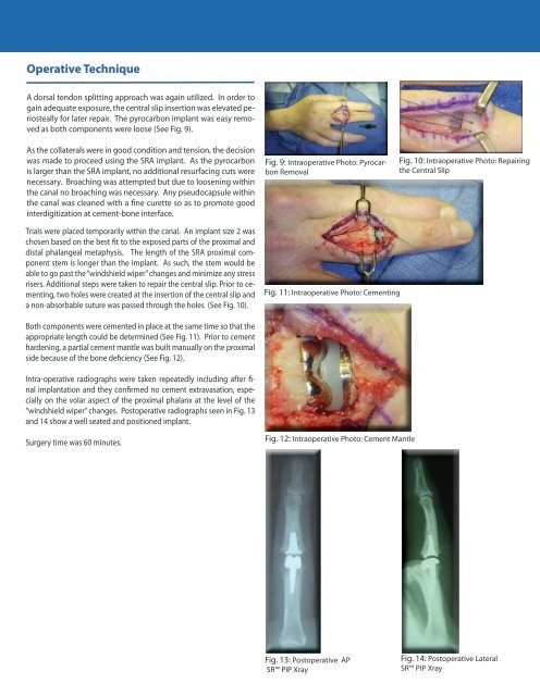
A dorsal tendon splitting approach was again utilized. In order to<br />
gain adequate exposure, the central slip insertion was elevated periosteally<br />
for later repair. The pyrocarbon implant was easy removed<br />
as both components were loose (See Fig. 9).<br />
As the collaterals were in good condition and tension, the decision<br />
was made to proceed using the SRA implant. As the pyrocarbon<br />
is larger than the SRA implant, no additional resurfacing cuts were<br />
necessary. Broaching was attempted but due to loosening within<br />
the canal no broaching was necessary. Any pseudocapsule within<br />
the canal was cleaned with a fine curette so as to promote good<br />
interdigitization at cement-bone interface.<br />
Fig. 9: Intraoperative Photo: Pyrocarbon<br />
Removal<br />
Fig. 10: Intraoperative Photo: Repairing<br />
the Central Slip<br />
Trials were placed temporarily within the canal. An implant size 2 was<br />
chosen based on the best fit to the exposed parts of the proximal and<br />
distal phalangeal metaphysis. The length of the SRA proximal component<br />
stem is longer than the implant. As such, the stem would be<br />
able to go past the “windshield wiper” changes and minimize any stress<br />
risers. Additional steps were taken to repair the central slip. Prior to cementing,<br />
two holes were created at the insertion of the central slip and<br />
a non-absorbable suture was passed through the holes (See Fig. 10).<br />
Fig. 11: Intraoperative Photo: Cementing<br />
Both components were cemented in place at the same time so that the<br />
appropriate length could be determined (See Fig. 11). Prior to cement<br />
hardening, a partial cement mantle was built manually on the proximal<br />
side because of the bone deficiency (See Fig. 12).<br />
Intra-operative radiographs were taken repeatedly including after final<br />
implantation and they confirmed no cement extravasation, especially<br />
on the volar aspect of the proximal phalanx at the level of the<br />
“windshield wiper” changes. Postoperative radiographs seen in Fig. 13<br />
and 14 show a well seated and positioned implant.<br />
Surgery time was 60 minutes.<br />
Fig. 12: Intraoperative Photo: Cement Mantle<br />
Fig. 13: Postoperative AP<br />
SR <strong>PIP</strong> Xray<br />
Fig. 14: Postoperative Lateral<br />
SR <strong>PIP</strong> Xray