CT Analyzer Brochure - Megavar
CT Analyzer Brochure - Megavar
CT Analyzer Brochure - Megavar

Create successful ePaper yourself
Turn your PDF publications into a flip-book with our unique Google optimized e-Paper software.
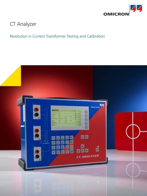
<strong>CT</strong> <strong>Analyzer</strong><br />
Revolution in Current Transformer Testing and Calibration
Revolutionary Way of <strong>CT</strong> Testing<br />
Current transformers are used for relaying and metering purposes<br />
in electrical power systems. They connect the high power primary<br />
side to the protection and metering equipment on the secondary<br />
side. Depending on the application they are used for, current<br />
transformers are designed differently.<br />
Protection current transformers<br />
As it is used to feed protective relays, the <strong>CT</strong> must be accurate<br />
during normal and fault conditions. Failures in transformation<br />
could lead to misoperation of the relay along with unwanted<br />
and costly outages. To test <strong>CT</strong>s according to the requirements of<br />
modern protection systems, it is compulsory to consider transient<br />
components and auto-reclosure systems.<br />
Metering current transformers<br />
<strong>CT</strong>s for metering purposes must provide high accuracy up to class<br />
0.1 to guarantee correct billing. It is therefore essential to test and<br />
calibrate the metering current transformer, as the entire metering<br />
chain is only as accurate as the instrument transformers feeding<br />
the meter.<br />
In contrast to protection <strong>CT</strong>s, metering <strong>CT</strong>s must go into<br />
saturation directly above the nominal primary current level to<br />
protect the connected metering equipment.<br />
<strong>CT</strong> <strong>Analyzer</strong> - a new way of testing <strong>CT</strong>s<br />
The <strong>CT</strong> <strong>Analyzer</strong> is the most complete testing system for<br />
protection and metering <strong>CT</strong>s according to IEEE and IEC standards.<br />
It allows all types of single and multi-ratio current transformers<br />
to be tested on-site in power system grids. Manufacturer of<br />
<strong>CT</strong>s, transformers or GIS use the <strong>CT</strong> <strong>Analyzer</strong> in their production<br />
facilities and test / development labs.<br />
The <strong>CT</strong> <strong>Analyzer</strong> offers a wide range of measurements, such as:<br />
2<br />
> > <strong>CT</strong>-ratio and phase-angle accuracy with consideration of<br />
nominal and operational burden for various currents<br />
> > <strong>CT</strong> winding resistance<br />
> > <strong>CT</strong> excitation / saturation (unsaturated and saturated)<br />
> > ALF and FS (direct and indirect)<br />
> > Burden impedance<br />
> > <strong>CT</strong> residual magnetism
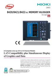
Automated testing procedure<br />
The <strong>CT</strong> <strong>Analyzer</strong> is designed to accurately measure all relevant <strong>CT</strong> parameters and compare them to the requirements of the<br />
defined IEEE or IEC standard. Due to this automated assessment, testing engineers receive the 'pass or fail' decision within seconds.<br />
Step 1<br />
Measurement of<br />
parameters<br />
Measurement of<br />
<strong>CT</strong> parameters like<br />
excitation curve,<br />
eddy current,<br />
ratio, etc.<br />
Step 2<br />
Modeling<br />
Definition of <strong>CT</strong> model elements and<br />
calculation of <strong>CT</strong> parameters through<br />
embedded mathematical functions<br />
Ψ(t)=Ψ' 0<br />
+ ∫ t (V S<br />
(t)-R <strong>CT</strong><br />
I <strong>CT</strong><br />
(t)) dt - L <strong>CT</strong> --- d<br />
0<br />
d(t) I (t) <strong>CT</strong><br />
V C<br />
(t)=V S<br />
(t)-R <strong>CT</strong><br />
I <strong>CT</strong><br />
(t)-L d<br />
<strong>CT</strong><br />
---<br />
d(t) I (t) <strong>CT</strong><br />
Step 4<br />
Reporting<br />
All data is delivered in an XML file<br />
and can be displayed via the<br />
reporting tool<br />
Step 3<br />
Assessment according<br />
to IEEE or IEC standard<br />
Automated comparison of test results<br />
with the defined<br />
POWER<br />
values according<br />
to the selected IEEE<br />
15 0.8<br />
or IEC standard<br />
Current ratio error in % at % of rated current<br />
VA cos φ Data type 1% 5% 10% 20% 50% 100% 120% 200%<br />
7.5 0.8<br />
String value -0.023 -0.023 -0.021 -0.018 -0.013 -0.010 -0.009 -0.008<br />
Float value -0.023 -0.023 -0.021 -0.018 -0.013 -0.010 -0.009 -0.008<br />
String value -0.008 -0.010 -0.010 -0.008 -0.006 -0.004 -0.003 -0.002<br />
Float value -0.008 -0.010 -0.010 -0.008 -0.006 -0.004 -0.003 -0.002<br />
3.75 1<br />
String value 0.005 0.001 0.000 -0.001 0.000 0.000 0.001 0.001<br />
Float value 0.005 0.001 0.000 -0.001 -0.000 0.000 0.001 0.001<br />
Your Benefits:<br />
> > Field verification of <strong>CT</strong>s up to the 0.1 accuracy class<br />
due to extremely high accuracy (0.02 % typical)<br />
> > Compact and lightweight (< 8 kg / 17.4 lbs)<br />
> > Automatic assessment according to<br />
IEEE and IEC standards<br />
> > Reduced testing time (typically < 1 min)<br />
> > High noise immunity for on-site testing<br />
3
Highly Accurate <strong>CT</strong> Verification Made Mobile<br />
The ideal way of testing a current transformer<br />
As energy is supplied by many different sources, power system grids for generation, transmission and distribution are expanded<br />
continuously. This makes the use of additional metering and protection <strong>CT</strong>s necessary. To test all of these <strong>CT</strong>s in a cost-effective and<br />
reliable way, the ideal <strong>CT</strong> test device fulfills the following requirements:<br />
Mobility<br />
Test engineers often have to maintain several <strong>CT</strong>s within one utility. The ideal <strong>CT</strong> test device would therefore be an all-in-one solution,<br />
light enough to be carried by one person. It should be able to measure all parameters without the need for any further equipment<br />
(such as a burden box).<br />
Accuracy<br />
Correct billing is only possible if metering <strong>CT</strong>s work within their specifications, for all secondary burdens and levels of primary current<br />
that are defined in the standards. To test and calibrate these metering <strong>CT</strong>s, measurement equipment delivering reliable results up to<br />
class 0.1 <strong>CT</strong>s is needed.<br />
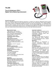
Primary Nominal Current Injection<br />
Primary Current Injection<br />
Mobility<br />
I P<br />
I S<br />
Mobility<br />
I P<br />
I S<br />
A<br />
Approx. 2 tons of equipment (high current source,<br />
huge cables, current booster, burden box etc.)<br />
> 30 kg / 66.1 lbs (Not including additional<br />
equipment, e.g. external burden box)<br />
Accuracy<br />
High accuracy, but complicated wiring makes<br />
testing error-prone<br />
Accuracy<br />
– Not sufficient for high accuracy metering <strong>CT</strong>s<br />
– Sensitive to transient distortion from life signals<br />
(due to the use of 50 Hz test signals)<br />
Safety<br />
Uses dangerously high voltages and currents<br />
(primary nominal current injection)<br />
Safety<br />
Typical current levels of 500 A to 800 A are used<br />
Handling<br />
Requires several people to set-up and<br />
conduct the test<br />
Handling<br />
– Re-wiring is required for each type of test<br />
(e.g. ratio, polarity, saturation, winding resistance)<br />
– Test results must be assessed manually<br />
4
Safety<br />
Equipment for testing <strong>CT</strong>s on-site must comply to applicable safety standards and regulations. However, the ideal test device avoids<br />
the use of high test currents and voltages and conducts tests with as low test voltages as possible to reduce the operator´s<br />
health and safety risks.<br />
Handling<br />
Short measurement times and an automated assessment to the respective IEC and IEEE standards characterize modern test equipment.<br />
All relevant parameters should be measured in one test cycle without the need for rewiring. Printable test reports, including all<br />
measured data and the assessment to the standard, are ideally created automatically by the test device.<br />
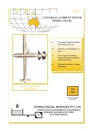
Secondary Voltage Injection<br />
<strong>CT</strong> as an Electrical Model<br />
V P<br />
V S<br />
V P<br />
V S<br />
(f)<br />
V<br />
V<br />
Mobility<br />
> 30 kg / 66.1 lbs (Not including additional<br />
equipment, e.g. external burden box)<br />
Mobility<br />
< 8 kg / 17.4 lbs; ideal for handling on site<br />
Accuracy<br />
– Not sufficient for high accuracy metering <strong>CT</strong>s<br />
– Sensitive to transient distortion from life signals<br />
(due to the use of 50 Hz test signals)<br />
Accuracy<br />
– Measurement of class 0.1 metering <strong>CT</strong>s<br />
– Excellent noise suppression guarantees<br />
highly accurate on-site testing even if active<br />
lines are close to the test object<br />
Safety<br />
Voltages for saturation tests can be<br />
2,000 V or more<br />
Safety<br />
Maximum output voltage of 120 V<br />
Handling<br />
– Re-wiring is required for each type of test<br />
(e.g. ratio, polarity, saturation, winding resistance)<br />
– Test results must be assessed manually<br />
Handling<br />
– One-step test determining all parameters (< 1 min)<br />
– Automated assessment to standard and<br />
integrated report functionality<br />
5
Extraordinary Features<br />
RemAlyzer<br />
> > Software-based tool to determine the residual magnetism in<br />
current transformers<br />
> > Analysis of the remanence condition before putting into<br />
operation the <strong>CT</strong> to assure proper function<br />
> > Simplifies power grid failure analysis after unwanted<br />
operation of protective relays<br />
> > Demagnetizes the <strong>CT</strong> core after measurement<br />
Remote Control<br />
> > Full access to all functions of the <strong>CT</strong> <strong>Analyzer</strong> via a PC using<br />
the remote interface<br />
> > Optimizes the integration into automated testing procedures<br />
in production lines<br />
> > Data export into Excel TM and Word TM<br />
> > Customizable testing and reports<br />
Network Simulation<br />
> > NetSim is a software tool for network simulation<br />
(part of the Test Universe software suite for relay testing)<br />
> > Easy transfer of <strong>CT</strong> <strong>Analyzer</strong> measurement data to NetSim<br />
> > Accurate modeling of power systems for network studies and<br />
fault simulation testing of protection relays<br />
> > Behavior analysis of protective relays in case of <strong>CT</strong> saturation<br />
Data Handling and Reporting<br />
> > Test reports can be saved on the Compact Flash Card and<br />
transferred to a PC<br />
> > Data and protocols can be shown on a PC via the Excel TM file<br />
loader program<br />
> > Customizable report templates are available, for example:<br />
> > Different standards, classes and applications<br />
> > Single, multi-core and multi-tap <strong>CT</strong>s<br />
> > Three-phase testing<br />
> > Core testing<br />
6
Verification for different burdens and currents<br />
> > Existing measurement data can be loaded to the <strong>CT</strong> <strong>Analyzer</strong><br />
at any time<br />
> > Recalculation of the <strong>CT</strong> parameters for different burdens<br />
and primary currents<br />
> > No further on-site measurements are necessary to verify<br />
whether a change in the burden will influence the accuracy<br />
of a <strong>CT</strong><br />
POWER<br />
Current ratio error in % at % of rated current<br />
VA cos Phi Data type 1% 5% 10% 20% 50% 100% 120% 200%<br />
String value -0.023 -0.023 -0.021 -0.018 -0.013 -0.010 -0.009 -0.008<br />
15 0.8<br />
Float value -0.023 -0.023 -0.021 -0.018 -0.013 -0.010 -0.009 -0.008<br />
String value -0.008 -0.010 -0.010 -0.008 -0.006 -0.004 -0.003 -0.002<br />
7.5 0.8<br />
Float value -0.008 -0.010 -0.010 -0.008 -0.006 -0.004 -0.003 -0.002<br />
String value 0.005 0.001 0.000 -0.001 0.000 0.000 0.001 0.001<br />
3.75 1<br />
Float value 0.005 0.001 0.000 -0.001 -0.000 0.000 0.001 0.001<br />
String value 0.007 0.005 0.004 0.003 0.003 0.003 0.004 0.004<br />
0 1<br />
Float value 0.007 0.005 0.004 0.003 0.003 0.003 0.004 0.004<br />
Manual Testing: QuickTest<br />
> > Use of the <strong>CT</strong> <strong>Analyzer</strong> as a multimeter with an integrated<br />
current and voltage source<br />
> > Perform manual tests (L, Z, R, ratio, polarity, burden etc.) for<br />
trouble-shooting and quick verification on site<br />
> > VT ratio check<br />
<strong>CT</strong> SB2 Switchbox<br />
> > Automated testing of multi-tap <strong>CT</strong>s without the need for<br />
rewiring<br />
> > Includes terminals for burden and primary resistance tests<br />
> > <strong>CT</strong>s with up to six taps can be tested<br />
> > Automatic wiring check before measuring<br />
> > Use attached to the <strong>CT</strong> <strong>Analyzer</strong> or as a standalone unit<br />
"Guessing" Nameplates<br />
> > Determination of unknown <strong>CT</strong> data<br />
> > Older <strong>CT</strong>s can be classified and put into service without<br />
contacting the manufacturer<br />
> > Determinable parameters include:<br />
> > <strong>CT</strong> type<br />
> > Class<br />
> > Ratio<br />
> > Knee point<br />
> > Power Factor<br />
> > Nominal and operating burden<br />
> > Winding resistance (primary and secondary)<br />
before test<br />
after test<br />
7
Technical Data<br />
Technical features Standard Package<br />
> > Excellent noise immunity to disturbances from energized power lines close to the measurement<br />
> > Automatic assessment according to IEC 60044-1, or IEEE C57.13 up to accuracy class ≥ 0.3<br />
> > Determination of ALF/ALFi and FS/FSi, Ts, and composite error for nominal and connected burden<br />
> > <strong>CT</strong> ratio and phase measurement with consideration of nominal and connected secondary burden<br />
> > Currents from 1% up to 400 % of the rated value<br />
> > Different burdens (full, ½, ¼, ⅛ burden)<br />
> > <strong>CT</strong> winding resistance measurement (primary and secondary)<br />
> > <strong>CT</strong> excitation curve (unsaturated and saturated)<br />
> > Saturation characteristic recording<br />
> > Direct comparison of excitation curve to a reference curve<br />
> > <strong>CT</strong> phase and polarity check<br />
> > Secondary burden measurement<br />
> > Automatic demagnetization of the <strong>CT</strong> after the test<br />
> > Small and lightweight (< 8 kg / 17.4 lbs)<br />
> > Short testing time due to fully automatic testing<br />
> > High level of safety using patented variable frequency method (max. 120 V)<br />
> > "Nameplate guesser" function for <strong>CT</strong>s with unknown data<br />
> > Remote control interface<br />
> > QuickTest: Manual testing interface<br />
> > Display readable in bright sunlight<br />
> > Simulation of measured data with different burdens<br />
and currents<br />
> > Easily adaptable reports (customizable)<br />
> > Knee-point voltage from 1 V up to 4 kV can be<br />
measured<br />
Additional features Advanced Package<br />
> > Automatic assessment for accuracy class > 0.1 (inclusive classes defined in the IEEE C57.13.6 standard)<br />
> > Measurement of transient behavior of TPS, TPX, TPY and TPZ type <strong>CT</strong>s<br />
> > Automatic assessment according to IEC 60044-6<br />
> > Determination of the transient dimensioning factor (Ktd)<br />
> > Knee-point voltage from 1 V up to 30 kV can be measured<br />
> > Considering Duty (C-O / C-O-C-O) e.g. auto-reclosure system<br />
8
Technical data <strong>CT</strong> <strong>Analyzer</strong><br />
Current Ratio Accuracy<br />
Ratio 1 - 2000<br />
Ratio 2000 - 5000<br />
Ratio 5000 - 10000<br />
Phase Displacement<br />
Resolution<br />
Accuracy<br />
0.02 % (typical) / 0.05 % (guaranteed)<br />
0.03 % (typical) / 0.1 % (guaranteed)<br />
0.05 % (typical) / 0.2 % (guaranteed)<br />
0.1 min<br />
1 min (typical) / 3 min (guaranteed)<br />
Winding Resistance<br />
Resolution<br />
1 mΩ<br />
Accuracy 0.05 % (typical) /<br />
0.1 % + 1 mΩ (guaranteed)<br />
Power Supply<br />
Input Voltage<br />
100 Vac to 240 Vac<br />
Permissible Input Voltage 85 Vac to 264 Vac<br />
Frequency<br />
50 / 60 Hz<br />
Permissible Frequency 45 Hz to 65 Hz<br />
Input Power<br />
500 VA<br />
Connection Standard AC socket 60320<br />
Output<br />
Output Voltage 0 Vac to 120 Vac<br />
Output Current 0 A eff<br />
to 5 A eff<br />
(15 A peak<br />
)<br />
Output Power 0 VA eff<br />
to 400 VA eff<br />
(1500 VA peak<br />
)<br />
Physical Dimensions<br />
Size (W x H x D)<br />
Weight<br />
360 x 285 x 145 mm<br />
9.2 x 7.2 x 3.7 in<br />
8 kg / 17.4 lbs (without accessories)<br />
Environment Conditions<br />
Operating<br />
-10 °C up to + 50 °C / 14 °F up to 122 °F<br />
Temperature<br />
Storage Temperature -25 °C up to + 70 °C / -13 °F up to 158 °F<br />
Humidity<br />
Relative humidity 5% up to 95% not<br />
condensing<br />
EMC<br />
EMC-Emission<br />
International<br />
Europe<br />
USA<br />
EMC-Immunity<br />
International IEC 61326-1<br />
Europe EN 61326-1<br />
The product adheres to the<br />
electromagnetic compatibility (EMC)<br />
Directive 2004 / 108 / EC (CE conform)<br />
IEC 61326-1 Class A<br />
EN 61326-1 Class A<br />
FCC Subpart B of Part 15 Class A<br />
Safety<br />
The product adheres to the low voltage<br />
Directive 2006 / 95 / EC (CE conform)<br />
International IEC 61010-1<br />
Europe EN 61010-1<br />
USA UL 61010-1<br />
Canada CSA C22.2 No. 1010.1-92<br />
Certificates from Independent Test Institutes<br />
KEMA Test Report<br />
PTB Test Report<br />
Wuhan HV Research Test Report<br />
Ordering information<br />
Name Order No. Description<br />
Standard Package VE000656 <strong>CT</strong> <strong>Analyzer</strong> Standard Package<br />
Advanced Package VE000654 <strong>CT</strong> <strong>Analyzer</strong> Advanced Package<br />
Upgrade Standard - Advanced VESM0653 Software upgrade from Standard to Advanced<br />
<strong>CT</strong> SB2 Kit VEHZ0696 Hardware extension to connect and test multi-ratio <strong>CT</strong>s<br />
Primary Resistance Kit VEHZ0684 4 pol cable and Kelvin clamps<br />
RemAlyzer VESM0657 Software License<br />
9
Accessories<br />
Accessories (part of Standard and Advanced Package)<br />
Coax cables<br />
VEHK0651 - with banana plugs<br />
2 x 3 m / 2 x 9.8 ft,<br />
1 x 10 m / 1 x 32.8 ft<br />
Battery clamps<br />
VEHZ0652 - with 4 mm / 0.2 in banana<br />
sockets (primary side<br />
connection)<br />
Crocodile clamps<br />
VEHZ0656 - with 4 mm / 0.2 in banana<br />
sockets (secondary side<br />
connection)<br />
Flexible terminal<br />
adapters<br />
VEHS0009 - with 12 x 4 mm / 0.2 in<br />
banana socket<br />
20 mm / 0.8 in opening<br />
width, 2 x red, 2 x black<br />
Compact Flash Card<br />
VEHZ0654 - 128 MB<br />
Memory space for at least<br />
416 test reports<br />
Compact Flash card<br />
reader<br />
VEHZ0655 - USB 2.0 Compact Flash<br />
card reader<br />
User manual VESD0605 - User manual Carry bag VEHP0018 - <strong>CT</strong> <strong>Analyzer</strong> carry bag<br />
Grounding (PE) cable<br />
VEHK0615 - 1 x 6 m / 1 x 19.7 ft,<br />
6 mm² / 0.01 sq in,<br />
(protective earth connection)<br />
USB - RS232<br />
converter cable<br />
VEHZ0014 - with Nullmodem cable<br />
Training <strong>CT</strong> VEHZ0643 - 300:5, class 0.5 FS 5 <strong>CT</strong> <strong>Analyzer</strong> PC<br />
software toolset<br />
VESM0800 - remote control software,<br />
QuickTest, Excel File Loader<br />
etc.<br />
Power cord<br />
depends - country-dependent<br />
10
Additional accessories<br />
Calibration <strong>CT</strong> VEHZ0649 - 2000:1 / 2000:5,<br />
class 0.02<br />
Coax cable<br />
VEHK0657 - with Kelvin clamps,<br />
3 m / 9.8 ft<br />
Pluggable winding<br />
VEHK0658 - Pluggable 23 turns<br />
winding<br />
Coax cables<br />
VEHK0654 - 3 m / 9.8 ft*<br />
VEHK0652 - 6 m / 19.7 ft*<br />
VEHK0653 - 10 m / 32.8 ft*<br />
VEHK0655 - 15 m / 49.2 ft*<br />
VEHK0656 - 100 m / 328.1 ft*<br />
* with banana plugs<br />
<strong>CT</strong> SB2 upgrade kit<br />
VEHZ0696 - <strong>CT</strong> SB2 inclusive<br />
accessories<br />
Transport case<br />
VEHP0068 - Transport case with<br />
wheels<br />
Primary resistance Kit<br />
VEHZ0684 - 4 pole cable 15 m / 49.2 ft<br />
(<strong>CT</strong> SB2 to <strong>CT</strong>prim),<br />
2x Kelvin clamps<br />
11
The <strong>CT</strong> SB2 Switch-Box is an accessory for the <strong>CT</strong> <strong>Analyzer</strong> that<br />
enables the automatic testing of multi-ratio current transformers<br />
(<strong>CT</strong>s) with up to 6 tap connections (X1 to X6). The <strong>CT</strong> SB2 is<br />
connected to all the taps of a multi-ratio <strong>CT</strong> as well as to the <strong>CT</strong><br />
<strong>Analyzer</strong>. Thus every ratio combination can be tested automatically<br />
by the <strong>CT</strong> <strong>Analyzer</strong>.<br />
Convenient Features<br />
The <strong>CT</strong> SB2 offers many convenient features for testing:<br />
• 6 channel secondary connection terminals<br />
• Color-coded terminals and cables to avoid connection errors<br />
• Automatic wiring check to help with trouble-shooting<br />
• Easy test setup using the <strong>CT</strong> <strong>Analyzer</strong> User Interface<br />
• Terminals for connection of primary resistance and secondary<br />
burden for full automatic test without re-wiring during test<br />
Flexibility on-site<br />
The <strong>CT</strong> SB2 can be easily attached to the <strong>CT</strong> <strong>Analyzer</strong> or placed<br />
separately beside. With a combined weight of 11 kg / 24 lbs,<br />
the <strong>CT</strong> <strong>Analyzer</strong> with the <strong>CT</strong> SB2 is convenient to carry and handle<br />
on-site. The <strong>CT</strong> SB2 makes the <strong>CT</strong> <strong>Analyzer</strong> the most flexible and<br />
complete solution for testing multi-ratio <strong>CT</strong>s.<br />
Scope of Delivery <strong>CT</strong> SB2<br />
Input Voltage<br />
Input Frequency<br />
Input Current<br />
Output Voltage*<br />
Output Current*<br />
Output Power*<br />
Dimensions (W x H x D)<br />
Weight<br />
Order Number<br />
Mobile – Compact – Automated<br />
Depicted: <strong>CT</strong> SB2<br />
<strong>CT</strong> SB2<br />
100 - 240 V<br />
50 - 60 Hz<br />
0.2 A<br />
0 - 120 V<br />
0 - 5 A<br />
0 - 400 VA<br />
284 x 220 x 68 mm<br />
11.2 x 8.7 x 2.7 in<br />
2.6 kg / 5.7 lbs<br />
VEHZ0696<br />
* Output of <strong>CT</strong> <strong>Analyzer</strong><br />
OMICRON is an international company serving the electrical<br />
power industry with innovative testing and diagnostic solutions.<br />
The application of OMICRON products allows users to assess<br />
the condition of the primary and secondary equipment on their<br />
systems with complete confidence. Services offered in the area of<br />
consulting, commissioning, testing, diagnosis, and training make<br />
the product range complete.<br />
Customers in more than 140 countries rely on the company’s<br />
ability to supply leading edge technology of excellent quality.<br />
Broad application knowledge and extraordinary customer support<br />
provided by offices in North America, Europe, South and East Asia,<br />
Australia, and the Middle East, together with a worldwide network<br />
of distributors and representatives, make the company a market<br />
leader in its sector.<br />
The following publications provide further information on the solutions described in this<br />
brochure:<br />
<strong>CT</strong> SB2<br />
Multi-Ratio Switch-Box for <strong>CT</strong> <strong>Analyzer</strong><br />
Datasheet <strong>CT</strong> SB2<br />
Switch Box<br />
For a complete list of available literature please visit our website.<br />
Americas<br />
OMICRON electronics Corp. USA<br />
12 Greenway Plaza, Suite 1510<br />
Houston, TX 77046, USA<br />
Phone: +1 713 830-4660<br />
+1 800-OMICRON<br />
Fax: +1 713 830-4661<br />
info@omicronusa.com<br />
Asia-Pacific<br />
OMICRON electronics Asia Limited<br />
Suite 2006, 20/F, Tower 2<br />
The Gateway, Harbour City<br />
Kowloon, Hong Kong S.A.R.<br />
Phone: +852 3767 5500<br />
Fax: +852 3767 5400<br />
info@asia.omicron.at<br />
Europe, Middle East, Africa<br />
OMICRON electronics GmbH<br />
Oberes Ried 1<br />
6833 Klaus, Austria<br />
Phone: +43 5523 507-0<br />
Fax: +43 5523 507-999<br />
info@omicron.at<br />
© OMICRON L205, January 2012<br />
Subject to change without notice<br />
www.omicron.at • www.omicronusa.com