Variable Frequency Drive Specifications Technical Data
Variable Frequency Drive Specifications Technical Data
Variable Frequency Drive Specifications Technical Data

You also want an ePaper? Increase the reach of your titles
YUMPU automatically turns print PDFs into web optimized ePapers that Google loves.
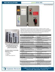
RECIRCULATION<br />
<strong>Variable</strong> <strong>Frequency</strong> <strong>Drive</strong>s<br />
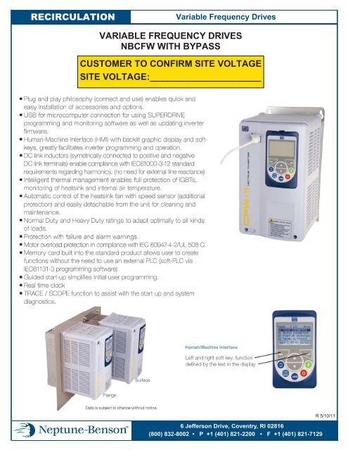
VARIABLE FREQUENCY DRIVES<br />
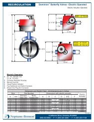
NBCFW WITH BYPASS<br />
CUSTOMER TO CONFIRM SITE VOLTAGE<br />
SITE VOLTAGE:______________________<br />
6 Jefferson <strong>Drive</strong>, Coventry, RI 02816<br />
(800) 832-8002 • P +1 (401) 821-2200 • F +1 (401) 821-7129<br />
R 5/10/11
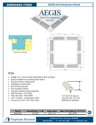
RECIRCULATION<br />
<strong>Variable</strong> <strong>Frequency</strong> <strong>Drive</strong>s<br />
VARIABLE FREQUENCY DRIVES<br />
NBCFW WITH BYPASS<br />
6 Jefferson <strong>Drive</strong>, Coventry, RI 02816<br />
(800) 832-8002 • P +1 (401) 821-2200 • F +1 (401) 821-7129<br />
R 5/10/11
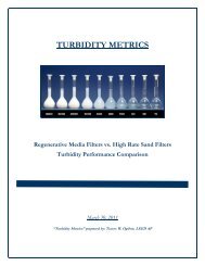
RECIRCULATION<br />
<strong>Variable</strong> <strong>Frequency</strong> <strong>Drive</strong>s<br />
VARIABLE FREQUENCY DRIVES<br />
NBCFW WITH BYPASS<br />
NEMA 4 ENCLOSURE<br />
THIS IS THE<br />
MANUAL BYPASS<br />
SWITCH. THE UNIT<br />
DOES CONTAIN A<br />
BYPASS (MOTOR<br />
STARTER)<br />
Horse<br />
Power<br />
Height<br />
(inches)<br />
Width<br />
(inches)<br />
Depth<br />
(inches)<br />
Horse<br />
Power Height<br />
(inches)<br />
Width<br />
(inches)<br />
Depth<br />
(inches)<br />
5 16 16 10.75<br />
5 16 16 10.75<br />
7.5 24 20 10.75<br />
7.5 16 16 10.75<br />
200 – 240 V<br />
10 24 20 10.75<br />
15 30 24 13.5<br />
20 30 24 13.5<br />
25 30 24 13.5<br />
30 36 30 13.5<br />
380 - 480 V<br />
10 24 20 10.75<br />
15 24 20 10.75<br />
20 24 20 10.75<br />
25 30 24 13.5<br />
30 30 24 13.5<br />
40 36 30 13.5<br />
40 30 24 13.5<br />
50 48 30 16.5<br />
50 36 30 13.5<br />
60 48 30 16.5<br />
60 36 30 13.5<br />
75 48 30 16.5<br />
75 48 30 16.5<br />
R 5/10/11<br />
6 Jefferson <strong>Drive</strong>, Coventry, RI 02816<br />
(800) 832-8002 • P +1 (401) 821-2200 • F +1 (401) 821-7129
VFD<br />
A. A <strong>Variable</strong> <strong>Frequency</strong> <strong>Drive</strong> (VFD) shall be provided for each filter pump motor.<br />
B. The <strong>Variable</strong> <strong>Frequency</strong> <strong>Drive</strong>s (VFDs) shall be solid state, with a Pulse Width Modulated (PWM)<br />
output. The VFD package as specified herein shall be enclosed in a NEMA 4 enclosure, completely<br />
assembled, programmed and tested by the manufacturer. The VFD shall employ a full wave rectifier<br />
(to prevent input line notching), capacitors, DC link inductors, and Insulated Gate Bipolar<br />
Transistors (IGBTs) as the output-switching device. The drive efficiency shall be 97% or better at<br />
full speed and full load. Displacement power factor shall be no less than 0.98 at all speeds and loads.<br />
C. All NBCFW VFDs shall be factory programmed per the unique requirements of each job per<br />
Neptune-Benson specifications. Programming shall include but shall not be limited to filter pump<br />
motor specifications, remote start/stop requirements, run confirm requirements and PID loop<br />
requirements.<br />
D. VFDs and options shall be UL and CUL listed as a complete assembly. VFDs and options shall be<br />
UL, CUL, and CE labeled as a component.<br />
E. Harmonic Distortion Control:<br />
The VFD design shall incorporate mechanisms that lower the harmonic currents caused by the drive<br />
as compared to standard six-pulse drives onto the AC power line. Harmonic calculations shall be<br />
supplied upon request based on a single line diagram of the electrical system. This diagram shall<br />
include transformer(s) KV, kVA and impedance percentage to accurately predict the harmonic levels<br />
at the PCC (Point of Common Coupling), as specified by IEEE519-1992. The calculations shall be<br />
made with the point of the common coupling being the utility feeder.<br />
F. <strong>Specifications</strong>:<br />
1. Input voltage 200-240, 380-480, 575-600 VAC +/- 10%, 3 phase, 48-63 Hz.<br />
2. Voltage tolerance + 10% or – 15% of specified line voltage.<br />
3. Output <strong>Frequency</strong> 0 to 300 Hz. Operation above 60 Hz shall require programming changes to<br />
prevent inadvertent high-speed operation.<br />
4. Environmental operating conditions: -10 to 50°C, 0 to 1000 meters above sea level, less than<br />
90% humidity, non-condensing.<br />
5. Enclosure shall be rated NEMA 4 or as specifically mentioned elsewhere.<br />
G. The VFD shall be wired into the RMF controller for on/off and run confirm functions. Wiring shall<br />
be by electrical contractor.<br />
H. The VFD shall be a WEG NBCFW series.<br />
I. The VFD shall be equipped with a bypass. Bypass option shall send the motor to bypass mode based<br />
on an easily accessible door-mounted selector or based on the drive’s programmable relay. A bypass<br />
pilot light shall provide indication of the bypass mode. The bypass mode shall provide overload<br />
protection. Contactors shall be electrically and mechanically interlocked. An essential services mode<br />
shall send the motor to bypass regardless of the selected mode.<br />
J. A disconnect switch, as may be required by local electrical codes, shall be provided by others.