90 AMP FLUX WIRE WELdER - Harbor Freight Tools
90 AMP FLUX WIRE WELdER - Harbor Freight Tools
90 AMP FLUX WIRE WELdER - Harbor Freight Tools

Create successful ePaper yourself
Turn your PDF publications into a flip-book with our unique Google optimized e-Paper software.
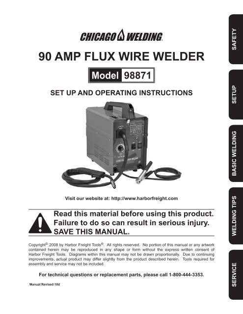
<strong>90</strong> <strong>AMP</strong> <strong>FLUX</strong> <strong>WIRE</strong> welder<br />
Model 98871<br />
Set up and Operating Instructions<br />
Visit our website at: http://www.harborfreight.com<br />
Read this material before using this product.<br />
Failure to do so can result in serious injury.<br />
Save this manual.<br />
Copyright © 2008 by <strong>Harbor</strong> <strong>Freight</strong> <strong>Tools</strong> ® . All rights reserved. No portion of this manual or any artwork<br />
contained herein may be reproduced in any shape or form without the express written consent of<br />
<strong>Harbor</strong> <strong>Freight</strong> <strong>Tools</strong>. Diagrams within this manual may not be drawn proportionally. Due to continuing<br />
improvements, actual product may differ slightly from the product described herein. <strong>Tools</strong> required for<br />
assembly and service may not be included.<br />
For technical questions or replacement parts, please call 1-800-444-3353.<br />
Manual Revised 10d<br />
Safety<br />
Service Welding Tips Basic Welding Setup
Safety Setup Basic Welding Welding Tips Service<br />
Save This Manual<br />
Keep this manual for the safety warnings<br />
and precautions, assembly, operating,<br />
inspection, maintenance and cleaning<br />
procedures. Write the product’s serial number<br />
in the back of the manual near the assembly<br />
diagram (or month and year of purchase if<br />
product has no number). Keep this manual<br />
and the receipt in a safe and dry place for<br />
future reference.<br />
Important SAFETY<br />
Information<br />
In this manual, on the labeling, and<br />
all other information provided with<br />
this product:<br />
This is the safety alert<br />
symbol. It is used to alert<br />
you to potential personal<br />
injury hazards. Obey all<br />
safety messages that follow<br />
this symbol to avoid possible<br />
injury or death.<br />
DANGER indicates a<br />
hazardous situation<br />
which, if not avoided, will result<br />
in death or serious injury.<br />
WARNING indicates a<br />
hazardous situation<br />
which, if not avoided, could<br />
result in death or serious injury.<br />
CAUTION, used with<br />
the safety alert<br />
symbol, indicates a hazardous<br />
situation which, if not avoided,<br />
could result in minor or moderate<br />
injury.<br />
1.<br />
2.<br />
NOTICE is used to<br />
address practices not<br />
related to personal injury.<br />
CAUTION, without the<br />
safety alert symbol, is<br />
used to address practices not<br />
related to personal injury.<br />
General Safety Warnings<br />
WARNING Read all safety warnings<br />
and instructions. Failure to follow the<br />
warnings and instructions may result<br />
in electric shock, fire and/or serious<br />
injury.<br />
Save all warnings and instructions<br />
for future reference.<br />
Work area safety<br />
a. Keep work area clean and well lit.<br />
Cluttered or dark areas invite accidents.<br />
b. Do not operate welders in explosive<br />
atmospheres, such as in the presence<br />
of flammable liquids, gases or dust.<br />
Welders create sparks which may ignite<br />
the dust or fumes.<br />
c. Keep children and bystanders away<br />
while operating a welder. Distractions<br />
can cause you to lose control.<br />
Electrical safety<br />
a. Welder plugs must match the outlet.<br />
Never modify the plug in any way.<br />
Do not use any adapter plugs with<br />
grounded welders. Unmodified plugs<br />
and matching outlets will reduce risk of<br />
electric shock.<br />
b. Avoid body contact with grounded<br />
surfaces such as pipes, radiators,<br />
ranges and refrigerators. There is an<br />
increased risk of electric shock if your<br />
body is grounded.<br />
c. Do not expose welders to rain or wet<br />
conditions. Water entering a welder will<br />
increase the risk of electric shock.<br />
Page 2 For technical questions, please call 1-800-444-3353. SKU 98871
3.<br />
d. Do not abuse the cord. Never use<br />
the cord for carrying, pulling or<br />
unplugging the welder. Keep cord<br />
away from heat, oil, sharp edges or<br />
moving parts. Damaged or entangled<br />
cords increase the risk of electric shock.<br />
e. When operating a welder outdoors,<br />
use an extension cord suitable for<br />
outdoor use. Use of a cord suitable for<br />
outdoor use reduces the risk of electric<br />
shock.<br />
f. If operating a welder in a damp<br />
location is unavoidable, use a Ground<br />
Fault Circuit Interrupter (GFCI)<br />
protected supply. Use of a GFCI<br />
reduces the risk of electric shock.<br />
Personal safety<br />
a. Stay alert, watch what you are<br />
doing and use common sense when<br />
operating a welder. Do not use a<br />
welder while you are tired or under<br />
the influence of drugs, alcohol or<br />
medication. A moment of inattention<br />
while operating welders may result in<br />
serious personal injury.<br />
b. Use safety equipment. Always wear<br />
ANSI-approved safety glasses and arc<br />
shaded, impact safety full face shield.<br />
Safety equipment such as NIOSHapproved<br />
respirator, heavy-duty work<br />
gloves, non-skid safety shoes, or<br />
hearing protection used for appropriate<br />
conditions will reduce personal injuries.<br />
c. Prevent unintentional starting. Ensure<br />
the switch is in the off-position<br />
before connecting to power source<br />
or moving the welder. Carrying or<br />
energizing welders that have the switch<br />
on invites accidents.<br />
d. Do not overreach. Keep proper<br />
footing and balance at all times. This<br />
enables better control of the welder in<br />
unexpected situations.<br />
4.<br />
e. Only use safety equipment that has<br />
been approved by an appropriate<br />
standards agency. Unapproved safety<br />
equipment may not provide adequate<br />
protection. Eye protection must be<br />
ANSI-approved and breathing protection<br />
must be NIOSH-approved for the specific<br />
hazards in the work area.<br />
Welder use and care<br />
a. Do not use the welder if the switch<br />
does not turn it on and off. Any welder<br />
that cannot be controlled with the switch<br />
is dangerous and must be repaired.<br />
b. Disconnect the plug from the<br />
power source before making any<br />
adjustments, changing accessories,<br />
or storing welders. Such preventive<br />
safety measures reduce the risk of<br />
starting the welder accidentally.<br />
c. Store idle welders out of the reach<br />
of children and do not allow persons<br />
unfamiliar with the welder or these<br />
instructions to operate the welder.<br />
Welders are dangerous in the hands of<br />
untrained users.<br />
d. Maintain welders. Check for<br />
misalignment or binding of moving<br />
parts, breakage of parts and any<br />
other condition that may affect the<br />
welder’s operation. If damaged,<br />
have the welder repaired before use.<br />
Many accidents are caused by poorly<br />
maintained welders.<br />
e. Use the welder and accessories in<br />
accordance with these instructions,<br />
taking into account the working<br />
conditions and the work to be<br />
performed. Use of the welder for<br />
operations different from those intended<br />
could result in a hazardous situation.<br />
Safety<br />
Service Welding Tips Basic Welding Setup<br />
SKU 98871<br />
For technical questions, please call 1-800-444-3353.<br />
Page 3
Safety Setup Basic Welding Welding Tips Service<br />
5.<br />
1.<br />
2.<br />
Service<br />
a. Have your welder serviced by a<br />
qualified repair person using only<br />
identical replacement parts. This will<br />
ensure that the safety of the welder is<br />
maintained.<br />
Welder Safety Warnings<br />
Maintain labels and nameplates on<br />
the Welder. These carry important<br />
information. If unreadable or missing,<br />
contact <strong>Harbor</strong> <strong>Freight</strong> <strong>Tools</strong> for a<br />
replacement.<br />
Maintain a safe working environment.<br />
Keep the work area well lit. Make<br />
sure there is adequate surrounding<br />
workspace. Always keep the work area<br />
free of obstructions, grease, oil, trash,<br />
and other debris.<br />
3. Avoid unintentional starting. Make<br />
sure you are prepared to begin work<br />
before turning on the Welder.<br />
4.<br />
5.<br />
Unplug before performing<br />
maintenance. Unplug the Welder from<br />
its electrical outlet before performing any<br />
inspection, maintenance, or cleaning<br />
procedures.<br />
Never leave the Welder unattended<br />
while energized. Turn power off if you<br />
have to leave the Welder.<br />
6. Prevent eye injury and<br />
burns. Wearing and using<br />
ANSI-approved personal<br />
safety clothing and safety<br />
devices reduce the risk for injury.<br />
• Wear ANSI-approved safety impact<br />
eye goggles underneath welding eye<br />
protection featuring at least a number<br />
10 shade lens rating, such as the one<br />
included.<br />
• Leather leggings, fire resistant shoes or<br />
boots should be worn when using this<br />
product. Do not wear pants with cuffs,<br />
shirts with open pockets, or any clothing<br />
that can catch and hold molten metal or<br />
sparks.<br />
• Keep clothing free of grease, oil,<br />
solvents, or any flammable substances.<br />
Wear dry, insulating gloves and<br />
protective clothing.<br />
• Wear an approved head covering to<br />
protect the head and neck. Use aprons,<br />
cape, sleeves, shoulder covers, and<br />
bibs designed and approved for welding<br />
and cutting procedures.<br />
• When welding/cutting overhead or in<br />
confined spaces, wear flame resistant<br />
ear plugs or ear muffs to keep sparks<br />
out of ears.<br />
7. Prevent accidental fires.<br />
Remove any combustible<br />
material from the work area.<br />
• When possible, move the work to a<br />
location well away from combustible<br />
materials. If relocation is not possible,<br />
protect the combustibles with a cover<br />
made of fire resistant material.<br />
• Remove or make safe all combustible<br />
materials for a radius of 35 feet (10<br />
meters) around the work area. Use a<br />
fire resistant material to cover or block<br />
all open doorways, windows, cracks,<br />
and other openings.<br />
• Enclose the work area with portable fire<br />
resistant screens. Protect combustible<br />
walls, ceilings, floors, etc., from sparks<br />
and heat with fire resistant covers.<br />
• If working on a metal wall, ceiling, etc.,<br />
prevent ignition of combustibles on the<br />
other side by moving the combustibles<br />
to a safe location. If relocation of<br />
combustibles is not possible, designate<br />
someone to serve as a fire watch,<br />
Page 4 For technical questions, please call 1-800-444-3353. SKU 98871
8.<br />
equipped with a fire extinguisher, during<br />
the cutting process and for at least one<br />
half hour after the cutting is completed.<br />
• Do not weld or cut on materials having<br />
a combustible coating or combustible<br />
internal structure, as in walls or ceilings,<br />
without an approved method for<br />
eliminating the hazard.<br />
• Do not dispose of hot slag in containers<br />
holding combustible materials. Keep a<br />
fire extinguisher nearby and know how<br />
to use it.<br />
• After spot welding, make a thorough<br />
examination for evidence of fire. Be<br />
aware that easily visible smoke or flame<br />
may not be present for some time after<br />
the fire has started. Do not weld or cut<br />
in atmospheres containing dangerously<br />
reactive or flammable gases, vapors,<br />
liquids, and dust. Provide adequate<br />
ventilation in work areas to prevent<br />
accumulation of flammable gases,<br />
vapors, and dust. Do not apply heat to<br />
a container that has held an unknown<br />
substance or a combustible material<br />
whose contents, when heated, can<br />
produce flammable or explosive vapors.<br />
Clean and purge containers before<br />
applying heat. Vent closed containers,<br />
including castings, before preheating,<br />
welding, or cutting.<br />
Avoid overexposure to fumes and<br />
gases. Always keep your head out of<br />
the fumes. Do not breathe the fumes.<br />
Use enough ventilation or exhaust, or<br />
both, to keep fumes and gases from your<br />
breathing zone and general area.<br />
• Where ventilation is questionable,<br />
have a qualified technician take an air<br />
sampling to determine the need for<br />
corrective measures. Use mechanical<br />
ventilation to improve air quality. If<br />
engineering controls are not feasible,<br />
use an approved respirator.<br />
• Work in a confined area only if it is<br />
well-ventilated, or while wearing an airsupplied<br />
respirator.<br />
• Follow OSHA guidelines for Permissible<br />
Exposure Limits (PEL’s) for various<br />
fumes and gases.<br />
• Follow the American Conference of<br />
Governmental Industrial Hygienists<br />
recommendations for Threshold Limit<br />
Values (TLV’s) for fumes and gases.<br />
• Have a recognized specialist in<br />
Industrial Hygiene or Environmental<br />
Services check the operation and air<br />
quality and make recommendations for<br />
the specific welding or cutting situation.<br />
WARNING<br />
Inhalation Hazard:<br />
Welding and Plasma Cutting Produce<br />
toxic fumes.<br />
Exposure to welding or cutting exhaust<br />
fumes can increase the risk of developing<br />
certain cancers, such as cancer of the<br />
larynx and lung cancer. Also, some<br />
diseases that may be linked to exposure to<br />
welding or plasma cutting exhaust fumes<br />
are:<br />
• Early onset of Parkinson’s Disease<br />
• Heart disease • Ulcers<br />
• Damage to the reproductive organs<br />
• Inflammation of the small intestine or<br />
stomach • Kidney damage<br />
• Respiratory diseases such as<br />
emphysema, bronchitis, or pneumonia<br />
Use natural or forced air ventilation and<br />
wear a respirator approved by NIOSH to<br />
protect against the fumes produced to<br />
reduce the risk of developing the above<br />
illnesses.<br />
Safety<br />
Service Welding Tips Basic Welding Setup<br />
SKU 98871<br />
For technical questions, please call 1-800-444-3353.<br />
Page 5
Safety Setup Basic Welding Welding Tips Service<br />
9. Do not touch live electrical parts.<br />
Wear dry, insulating gloves. Do not touch<br />
welding wire or gun with bare hand. Do<br />
not wear wet or damaged gloves.<br />
10.<br />
11.<br />
12.<br />
13.<br />
14.<br />
Protect yourself from electric shock.<br />
Do not use outdoors. Insulate yourself<br />
from the workpiece and ground. Use<br />
nonflammable, dry insulating material<br />
if possible, or use dry rubber mats, dry<br />
wood or plywood, or other dry insulating<br />
material big enough to cover your full<br />
area of contact with the work or ground.<br />
People with pacemakers should<br />
consult their physician(s) before<br />
using this product. Electromagnetic<br />
fields in close proximity to a heart<br />
pacemaker could cause interference to,<br />
or failure of the pacemaker.<br />
Use care not to touch the welding tip<br />
to grounded material whenever the<br />
unit is plugged in. This unit is what<br />
is referred to as a “hot tip” welder,<br />
meaning that current is available to<br />
the wire at all times that the power<br />
Switch (7a) is in the ON position.<br />
Electric shock, fire, or burns may happen<br />
if appropriate precautions are not taken.<br />
Ensure that the unit is placed on a<br />
stable location before use. If this unit<br />
falls while plugged in, severe injury,<br />
electric shock, or fire may result.<br />
This product, when used for welding<br />
and similar applications, contains or<br />
produces a chemical known to the State<br />
of California to cause cancer and birth<br />
defects (or other reproductive harm).<br />
(California Health & Safety Code §<br />
25249.5, et seq.)<br />
15.<br />
16.<br />
Handling the cord on this product will<br />
expose you to lead, a chemical known to<br />
the State of California to cause cancer,<br />
and birth defects or other reproductive<br />
harm. Wash hands after handling.<br />
(California Health & Safety Code §<br />
25249.5, et seq.)<br />
The warnings, precautions, and<br />
instructions discussed in this instruction<br />
manual cannot cover all possible<br />
conditions and situations that may occur.<br />
It must be understood by the operator<br />
that common sense and caution are<br />
factors which cannot be built into this<br />
product, but must be supplied by the<br />
operator.<br />
Save these<br />
instructions.<br />
Grounding<br />
To prevent<br />
electric shock<br />
and death from incorrect<br />
grounding wire<br />
connection:<br />
Check with a qualified electrician<br />
if you are in doubt as to whether<br />
the outlet is properly grounded.<br />
Have a plug installed by a<br />
certified electrician. Do not use<br />
the welder if the power cord or<br />
plug is damaged. If damaged,<br />
have it repaired by a service<br />
facility before use. If the plug will<br />
not fit the outlet, have a proper<br />
outlet installed by a qualified<br />
electrician.<br />
Page 6 For technical questions, please call 1-800-444-3353. SKU 98871
1.<br />
Grounded Welders<br />
The grounding prong in the plug is<br />
connected through the green wire inside<br />
the cord to the grounding system in<br />
the welder. The green wire in the cord<br />
must be the only wire connected to the<br />
welder’s grounding system and must<br />
never be attached to an electrically “live”<br />
terminal.<br />
6.<br />
7.<br />
If you are using an extension cord<br />
outdoors, make sure it is marked with the<br />
suffix “W-A” (“W” in Canada) to indicate it<br />
is acceptable for outdoor use.<br />
Make sure the extension cord is properly<br />
wired and in good electrical condition.<br />
Always replace a damaged extension<br />
cord or have it repaired by a qualified<br />
electrician before using it.<br />
Safety<br />
2.<br />
1.<br />
2.<br />
3.<br />
4.<br />
5.<br />
The welder must be plugged into an<br />
appropriate outlet, properly installed and<br />
grounded in accordance with all codes<br />
and ordinances.<br />
Extension Cords<br />
If an extension cord is used, it must<br />
have the following wire size: up to 30<br />
feet, use 10 AWG size wire; 30 to 50<br />
feet, use 8 AWG wire; Over 50 feet,<br />
use 6 AWG wire.<br />
As the distance from the supply outlet<br />
increases, you must use a heavier gauge<br />
extension cord. Using extension cords<br />
with inadequately sized wire causes a<br />
serious drop in voltage, resulting in loss<br />
of power and possible welder damage.<br />
The smaller the gauge number of the<br />
wire, the greater the capacity of the cord.<br />
For example, a 14 gauge cord can carry<br />
a higher current than a 16 gauge cord.<br />
When using more than one extension<br />
cord to make up the total length, make<br />
sure each cord contains at least the<br />
minimum wire size required.<br />
If you are using one extension cord<br />
for more than one welder, add the<br />
nameplate amperes and use the sum to<br />
determine the required minimum cord<br />
size.<br />
8.<br />
Protect the extension cords from sharp<br />
objects, excessive heat, and damp or<br />
wet areas.<br />
V~<br />
A<br />
OCV<br />
KVA<br />
IPM<br />
AWG<br />
Symbology<br />
Wire Feed (Speed)<br />
Workpiece Ground Cable<br />
Gun Cable<br />
Overheat Shutdown Indicator<br />
Cooling Fan<br />
Housing Ground Point<br />
Volts Alternating Current<br />
Amperes<br />
Open Circuit Voltage<br />
Kilovolt Amperes<br />
(Volts / 1000 * Amperes)<br />
Inches Per Minute<br />
American Wire Gauge<br />
Service Welding Tips Basic Welding Setup<br />
SKU 98871<br />
For technical questions, please call 1-800-444-3353.<br />
Page 7
Safety Setup Basic Welding Welding Tips Service<br />
Specifications<br />
120 V~, 24 A (peak), 1-phase<br />
Power Input<br />
Connect to at least 20 A dedicated circuit<br />
DCEN<br />
MIN: 63 ~ 68 A<br />
Welding Output<br />
MAX: 79 ~ <strong>90</strong> A<br />
HOT TIP welder<br />
22 gauge (0.03”) to 3/16” (0.19”) mild steel only<br />
Capacity<br />
Not for welding aluminum or stainless steel<br />
25% at MAX setting<br />
Duty Cycle<br />
45% at MIN setting<br />
(See explanation on page 16)<br />
Open Circuit Voltage 31<br />
KVA 3.6<br />
Wire Speed<br />
101 – 342 IPM<br />
Ground: 6 AWG, 6’<br />
Cable Sizes<br />
Gun: 8 AWG, 6’<br />
Power: 3-wire, 14 AWG<br />
Welder Tips / Wire Size Installed tip will accept .030” to .035” flux core wire<br />
Wire Spool Capacity 4” diameter / 2 lb. spool<br />
Internal Fuse 2 A 250 V Tube fuse (see page 27)<br />
Spare Welder Tip (for .030” to .035” wire)<br />
Accessories<br />
Welding Face Shield<br />
Combination Wire Brush / Chipping Hammer<br />
Unpacking<br />
When unpacking, make sure that the item is intact and undamaged. If any parts are<br />
missing or broken, please call <strong>Harbor</strong> <strong>Freight</strong> <strong>Tools</strong> at 1-800-444-3353 as soon as possible.<br />
Page 8 For technical questions, please call 1-800-444-3353. SKU 98871
SETUP<br />
Read the entire Important Safety Information section at the beginning<br />
of this manual including all text under subheadings therein before set up or use<br />
of this product.<br />
To prevent serious injury from accidental operation:<br />
Turn the Power Switch off and unplug the welder before assembly.<br />
Safety<br />
Face Shield (38) Assembly<br />
Attach the handle to the Face Shield (38)<br />
by lining up the two rectangular tabs on<br />
the handle with the corresponding holes in<br />
the face shield and<br />
A. press the tabs through the holes and<br />
then<br />
B. slide the tabs forward from the back,<br />
locking the round tab in place.<br />
Cover (31) Assembly<br />
1. Slide the Handle (30) into the slot on the<br />
Cover (31) from the front.<br />
The notch on the back of the Handle<br />
should drop into the slot in the Cover.<br />
Both ends of the Handle should lay flush<br />
against the top of the Cover.<br />
Then, secure using Screw (29) as shown.<br />
2. Attach the Cover Latch (8) to the front of<br />
the Base Frame (14) using the Bolt (42),<br />
Washer (40), Lock Washer (50) and Nut<br />
(41) as shown.<br />
notch drops<br />
into slot on<br />
Cover here<br />
Nut<br />
(41)<br />
B<br />
A<br />
B<br />
A<br />
Face<br />
Shield<br />
(viewed from front)<br />
Washer<br />
(40)<br />
Lock<br />
Washer (50)<br />
Screw<br />
(29)<br />
Cover<br />
(31)<br />
Round<br />
Tab<br />
Handle<br />
Handle (30)<br />
Cover<br />
Latch (8)<br />
Bolt<br />
(42)<br />
Service Welding Tips Basic Welding Setup<br />
SKU 98871<br />
For technical questions, please call 1-800-444-3353.<br />
Page 9
Gun<br />
Safety Setup Basic Welding Welding Tips Service<br />
Wire Spool (27) Installation<br />
1. Turn the welder OFF and unplug it<br />
before proceeding.<br />
2. Press in the Cover Latch (8) on the front<br />
of the handle, then open the Cover (31).<br />
3. Remove the Wing Nut (25) and the Spool<br />
Retaining Nut (26). If replacing a Spool,<br />
remove the old Spool and all remaining<br />
wire from the liners.<br />
4.<br />
5.<br />
Make sure the Spool Spring (24) is in<br />
place on the Spool Spindle (28).<br />
Place the new flux core Wire Spool over<br />
the Spool Spindle (28) and on top of the<br />
Spool Spring (24) as illustrated.<br />
To prevent wire feed problems,<br />
set the Spool so that it will unwind<br />
counterclockwise.<br />
Secure Spool in place with the Spool<br />
Retaining Nut (26), then the Wing Nut<br />
(25).<br />
2<br />
3<br />
1<br />
4<br />
0<br />
5<br />
6<br />
10<br />
wire-Feed Speed<br />
7<br />
9<br />
8<br />
min<br />
mAx<br />
<strong>90</strong> Amp Flux wire welder<br />
On<br />
OFF<br />
120 V~<br />
60 Hz<br />
Cover (31)<br />
Cover<br />
Latch (8)<br />
wire must<br />
unwind this<br />
direction<br />
Wire<br />
Spool<br />
(27)<br />
Wing Nut (25)<br />
Spool Retaining Nut (26)<br />
Wire Spool (27)<br />
Spool Spring (24)<br />
Spool Spindle (28)<br />
Page 10 For technical questions, please call 1-800-444-3353. SKU 98871
6. Turn the Feed Tensioner (37) knob<br />
counterclockwise to loosen it enough to<br />
pull it up, releasing tension.<br />
Do not loosen the Tensioner knob too<br />
much, or the Tensioner will come apart.<br />
Then, swing the Feed Swing Arm (36)<br />
out.<br />
Feed Swing<br />
Arm (36)<br />
Feed<br />
Tensioner (37)<br />
Safety<br />
7. Compare the wire diameter marked on<br />
the Wire Spool (27) with the stamped<br />
number on the top of the Feed Roller<br />
(34). The Roller’s groove size must be<br />
compatible with the wire diameter -<br />
.8mm rollers also work with .030” wire &<br />
.9mm rollers also work with .035” wire.<br />
If it is not compatible or the number on<br />
the Roller is hidden:<br />
A. Remove the Screws (45) and Washers<br />
(46) from the Feed Roller Bracket (44).<br />
B. Remove the Feed Roller Bracket.<br />
Flip the Feed Roller (34) as needed and<br />
confirm that the number facing up is the<br />
same as the wire diameter on the Spool.<br />
C. Reassemble using the Feed Roller<br />
Bracket, Washers, and Screws.<br />
IMPORTANT:<br />
Securely hold onto the end of the welding<br />
wire and keep tension on it during the<br />
following steps.<br />
If this is not done, the welding wire will<br />
unravel and create a tangled “bird’s nest”,<br />
wasting wire.<br />
8.<br />
Cut off all bent and crimped wire. Make<br />
sure that the cut end has no burrs or<br />
sharp edges; cut again if needed.<br />
9. Keep tension on the wire and guide at<br />
least 12 inches of wire into the Wire<br />
Liners.<br />
Wire<br />
Liner<br />
(4)<br />
Screws (45),<br />
Washers (46)<br />
.030”<br />
Feed<br />
Roller (34)<br />
A<br />
C<br />
B<br />
leader<br />
wire liner<br />
Hold Wire<br />
Securely<br />
Feed Roller<br />
Bracket (44)<br />
welding<br />
wire<br />
Wire<br />
Spool<br />
Service Welding Tips Basic Welding Setup<br />
SKU 98871<br />
For technical questions, please call 1-800-444-3353.<br />
Page 11
Safety Setup Basic Welding Welding Tips Service<br />
10. Swing the Wire Feed Swing Arm (36)<br />
closed, and swing the Feed Tensioner<br />
(37) across the tip of the Arm, to latch it.<br />
Make sure the Welding Wire is resting<br />
in the top groove of the Feed Roller<br />
(34), then turn the Feed Tensioner knob<br />
clockwise a couple of turns.<br />
After the wire is held by the Tensioner,<br />
you may release it.<br />
11. Pull the Nozzle (3) to remove it.<br />
12.<br />
13.<br />
Using the third oval hole on the Multiwrench<br />
(43), turn the Contact Tip (2b)<br />
counterclockwise and remove.<br />
Lay the Gun Cable out in a straight line<br />
so that the wire moves through it easily.<br />
Leave the cover open, so that the feed<br />
mechanism can be observed.<br />
14. Do not touch the Gun’s Trigger (1c).<br />
Plug the Power Cord into its electrical<br />
outlet and turn the welder ON.<br />
1.<br />
2.<br />
Feed Swing<br />
Arm (36)<br />
Nozzle<br />
(3)<br />
Contact<br />
Tip (2b)<br />
Feed<br />
Tensioner (37)<br />
Gun<br />
WARNING<br />
The following steps require applying power to the welder<br />
with the cover open.<br />
To prevent serious injury from fire or electric shock:<br />
Do not touch anything, especially not the Ground Clamp,<br />
with the Gun or welding wire or an arc will be ignited.<br />
Do not touch internal welder components while it is<br />
plugged in.<br />
2<br />
3<br />
1<br />
4<br />
0<br />
Gun<br />
5<br />
6<br />
10<br />
wire-Feed Speed<br />
7<br />
9<br />
8<br />
min<br />
mAx<br />
<strong>90</strong> Amp Flux wire welder<br />
On<br />
OFF<br />
120 V~<br />
60 Hz<br />
Page 12 For technical questions, please call 1-800-444-3353. SKU 98871
15. Point the Gun away from all objects and<br />
press the Trigger (1c) until the wire feeds<br />
out of the gun two inches.<br />
The Wire Liner (4) may come out with<br />
the welding wire, this is normal, just<br />
push the Wire Liner back into the Gun.<br />
If the wire does not feed properly and the<br />
Spool is stationary, turn the welder OFF,<br />
unplug it, and slightly tighten the Feed<br />
Tensioner (37) clockwise before retrying.<br />
Welding<br />
Wire<br />
2”<br />
Gun<br />
Safety<br />
16. To check the wire’s drive tension, feed the<br />
wire against a piece of wood from 2 to 3<br />
inches away. If the wire stops instead of<br />
bending, turn the welder OFF, unplug it,<br />
slightly tighten the Feed Tensioner (37)<br />
clockwise, and try again.<br />
If the wire bends from the feed tension,<br />
then the tension is set properly.<br />
17. Turn the welder OFF.<br />
18. Select a Contact Tip that is compatible<br />
with the welding wire used. The included<br />
Tip (2b, .035”) will work with both .030”<br />
and .035” wire. Slide the Contact Tip over<br />
the wire and thread it clockwise into the<br />
Gun. Tighten the Contact Tip using the<br />
Multi-wrench (43).<br />
19.<br />
20.<br />
Replace the Nozzle (3) and cut the wire<br />
off at 1 / 2 ” from tip ( 1 / 2 ” stickout).<br />
Swing the Cover (31) closed until the<br />
Cover Latch (8) locks in place.<br />
2<br />
3<br />
1<br />
Nozzle<br />
(3)<br />
4<br />
0<br />
Gun<br />
5<br />
6<br />
10<br />
wire-Feed Speed<br />
<strong>90</strong> Amp Flux wire welder<br />
Contact<br />
Tip (2b)<br />
7<br />
9<br />
8<br />
Incrementally<br />
increase tension<br />
until<br />
wire bends.<br />
min<br />
mAx<br />
On<br />
OFF<br />
120 V~<br />
60 Hz<br />
Gun<br />
2-3”<br />
Service Welding Tips Basic Welding Setup<br />
SKU 98871<br />
For technical questions, please call 1-800-444-3353.<br />
Page 13
Safety Setup Basic Welding Welding Tips Service<br />
Basic Welding<br />
Read the entire Important<br />
Safety Information<br />
section at the beginning of this<br />
manual including all text under<br />
subheadings therein before<br />
welding.<br />
TO PREVENT SERIOUS<br />
INJURY:<br />
Protective gear must be worn<br />
when using the Welder; minimum<br />
shade number 10 full face shield<br />
(or welding mask), ear protection,<br />
welding gloves, sleeves and<br />
apron, NIOSH-approved respirator,<br />
and fire resistant work clothes<br />
without pockets should be worn<br />
when welding.<br />
Light from the arc can cause<br />
permanent damage to the eyes<br />
and skin.<br />
Do not breathe arc fumes.<br />
TO PREVENT SERIOUS<br />
INJURY, FIRE AND<br />
BURNS:<br />
5<br />
4<br />
6<br />
3<br />
7<br />
Keep welding tip clear of<br />
2<br />
8<br />
grounded objects whenever unit<br />
1<br />
9<br />
0<br />
10<br />
is plugged in.<br />
wire-Feed Speed<br />
This welder is a “hot tip” welder,<br />
meaning that current is available<br />
to the wire whenever the Power<br />
Switch is on.<br />
The Flux Wire Welder is used to weld<br />
sheet metal and low carbon steel. Good<br />
welding takes a degree of skill and experience.<br />
Practice a few sample welds on scrap before<br />
welding your first project. Additional practice<br />
periods are recommended whenever you<br />
weld a different thickness of material or weld<br />
a different type of connection. Make practice<br />
welds on pieces of scrap to practice<br />
technique before welding anything of value.<br />
Gun<br />
<strong>90</strong> Amp Flux wire welder<br />
=<br />
Page 14 For technical questions, please call 1-800-444-3353. SKU 98871<br />
min<br />
mAx<br />
On<br />
OFF<br />
120 V~<br />
60 Hz<br />
Practice your welding<br />
technique on scrap<br />
pieces before welding<br />
anything of value.<br />
REV 09f
Control Panel Layout<br />
Gun (1)<br />
Cable<br />
Wire<br />
Speed<br />
Dial (9)<br />
Ground<br />
Cable (33)<br />
Gun<br />
wire-Feed Speed<br />
Gun Cable: The welding Gun connects here.<br />
The wire and welding current feeds to<br />
the weld through here.<br />
The welding Gun is energized whenever<br />
the Power Switch is on.<br />
Wire Speed Dial: This controls the speed<br />
that the welding wire feeds out of the<br />
welding Gun.<br />
Adjust this according to the weld settings<br />
chart to achieve a good weld.<br />
Ground Cable: This connects to the base<br />
metal to provide a good connection for<br />
the current to travel back to the welder.<br />
2<br />
3<br />
1<br />
4<br />
0<br />
5<br />
6<br />
10<br />
7<br />
9<br />
8<br />
min<br />
mAx<br />
<strong>90</strong> Amp Flux wire welder<br />
On<br />
OFF<br />
120 V~<br />
60 Hz<br />
Overload<br />
Indicator<br />
(22)<br />
Power<br />
Switch (7a)<br />
Current<br />
Switch (7b)<br />
Power<br />
Cord (32)<br />
Power Cord: Plug the Power Cord into a<br />
properly grounded 120 V~ outlet, on at<br />
least a 20 amp dedicated circuit with<br />
delayed action type circuit breaker or<br />
fuses.<br />
Current Switch: This controls the output<br />
amperage of the welder.<br />
Adjust this according to the weld settings<br />
chart to achieve a good weld.<br />
Power Switch: This turns on power to the<br />
welding Gun and internal cooling fan.<br />
The welding Gun is energized whenever<br />
the Power Switch is on.<br />
Overload Indicator: This lights up if<br />
duty cycle work period is exceeded,<br />
overheating the welder. Rest the Gun<br />
on an electrically non-conductive, heatresistant<br />
surface, such as a concrete<br />
slab, well clear of the ground clamp<br />
while allowing the welder to cool with the<br />
Power Switch on, so the Fan can help<br />
cool the welder. Once the welder cools<br />
enough to be used again, use shorter<br />
welding periods and longer rest periods<br />
to prevent needless wear.<br />
Safety<br />
Service Welding Tips Basic Welding Setup<br />
SKU 98871<br />
For technical questions, please call 1-800-444-3353.<br />
Page 15
Safety Setup Basic Welding Welding Tips Service<br />
NOTE: The numbers within the<br />
spaces are the approximate wire<br />
feed settings recommended* for this<br />
wire size and material thickness.<br />
.030” Wire Size<br />
(Flux Core, Mild Steel)<br />
.035” Wire Size<br />
(Flux Core, Mild Steel)<br />
Weld Settings Chart<br />
22<br />
Gauge<br />
1<br />
speed<br />
0.5<br />
speed<br />
Material Thickness (Steel)<br />
18<br />
Gauge<br />
16<br />
Gauge<br />
MIN current<br />
1.5<br />
speed<br />
1.5<br />
speed<br />
2<br />
speed<br />
2<br />
speed<br />
14<br />
Gauge<br />
4<br />
speed<br />
3<br />
speed<br />
1 / 8 ” 3 / 16 ”<br />
MAX current<br />
8<br />
speed<br />
8<br />
speed<br />
9<br />
speed<br />
9.5<br />
speed<br />
* This chart is only intended to show general guidelines for different wire sizes and for different<br />
thicknesses of material. The settings should only be used at the beginning of a weld and must be<br />
adjusted after stopping and carefully inspecting the weld. Proper welding takes experience.<br />
Duty Cycle (Duration of Use)<br />
Avoid damage to the Welder by not<br />
welding for more than the prescribed<br />
duty cycle time. The Duty Cycle defines the<br />
number of minutes, within a 10 minute period,<br />
during which a given welder can produce a<br />
particular welding current without overheating.<br />
For example, this Welder with a 25% duty<br />
cycle on MAX setting must be allowed to<br />
rest for at least 7 minutes, 30 seconds after<br />
every 2 minutes, 30 seconds of continuous<br />
weld. Failure to carefully observe duty cycle<br />
limitations can easily over-stress a welder’s<br />
power generation system contributing to<br />
premature welder failure.<br />
This welder has an internal thermal<br />
protection system to help prevent this sort<br />
of over-stress. When the unit overheats, it<br />
automatically shuts down and the Overload Gun<br />
Indicator (22) lights, then the welder<br />
automatically returns to service after cooling<br />
off. Rest the Gun on an electrically nonconductive,<br />
heat-proof surface, such as a<br />
5<br />
4<br />
concrete slab, well clear of the ground clamp<br />
3<br />
while allowing the welder to cool with the 2<br />
1<br />
Power Switch on, so that the internal Fan will<br />
0<br />
help cool the welder. When the welder can be<br />
used again, use shorter welding periods and<br />
longer rest periods to prevent needless wear.<br />
wire-Feed Speed<br />
25% Duty Cycle at MAX setting<br />
2 minutes, 30 seconds welding<br />
followed by<br />
at least 7 minutes, 30 seconds of rest<br />
45% Duty Cycle at MIN setting<br />
4 minutes, 30 seconds welding<br />
followed by<br />
at least 5 minutes, 30 seconds of rest<br />
<strong>90</strong> Amp Flux wire welder<br />
Page 16<br />
120 V~<br />
60 Hz<br />
For technical questions, please call 1-800-444-3353. SKU 98871<br />
6<br />
10<br />
7<br />
9<br />
8<br />
min<br />
mAx<br />
On<br />
OFF<br />
Gun<br />
concrete slab<br />
(or other heat-proof,<br />
non-conductive<br />
surface)
2<br />
3<br />
1<br />
4<br />
0<br />
Gun<br />
5<br />
6<br />
10<br />
wire-Feed Speed<br />
7<br />
9<br />
8<br />
min<br />
mAx<br />
On<br />
OFF<br />
120 V~<br />
60 Hz<br />
1.<br />
Setting Up The Weld<br />
Make practice welds on pieces of scrap<br />
the same thickness as your intended<br />
workpiece to practice technique before<br />
welding anything of value. Clean the<br />
weld surfaces thoroughly with a wire<br />
brush or angle grinder; there must be no<br />
rust, paint, oil, or other materials on the<br />
weld surfaces, only bare metal.<br />
2. Use clamps (not included) to hold the<br />
workpieces in position so that you can<br />
concentrate on proper welding technique.<br />
The distance (if any) between the two<br />
workpieces must be controlled properly to<br />
allow the weld to hold both sides securely<br />
while allowing the weld to penetrate<br />
fully into the joint. The edges of thicker<br />
workpieces may need to be chamfered (or<br />
beveled) to allow proper weld penetration.<br />
3. Clamp Ground Cable to bare metal on<br />
the workpiece near the weld area, or to<br />
metal work bench where the workpiece is<br />
clamped.<br />
4. Set the Wire Speed Dial and the Current<br />
Switch to the desired settings.<br />
Refer to the chart on the welder or the<br />
chart on the facing page.<br />
DO NOT SWITCH THE CURRENT<br />
WHILE WELDING.<br />
5. Flip the Power Switch to the OFF position,<br />
5<br />
4<br />
6<br />
then plug the Welder into a dedicated, 3<br />
2<br />
120 V~, 20 A circuit with delayed action<br />
1<br />
0<br />
10<br />
type circuit breaker or fuses.<br />
Gun<br />
wire-Feed Speed<br />
7<br />
9<br />
8<br />
2<br />
3<br />
1<br />
4<br />
0<br />
<strong>90</strong> Amp Flux wire welder<br />
Gun<br />
5<br />
wire-Feed Speed<br />
<strong>90</strong> Amp Flux wire welder<br />
min<br />
mAx<br />
<strong>90</strong> Amp Flux wire welder<br />
6<br />
10<br />
7<br />
9<br />
8<br />
On<br />
OFF<br />
120 V~<br />
60 Hz<br />
clamps<br />
workpieces<br />
Clean<br />
surfaces to<br />
bare metal.<br />
Chamfer thick workpieces.<br />
min<br />
mAx<br />
On<br />
3<br />
2<br />
1<br />
OFF+<br />
120 V~<br />
60 Hz<br />
Ground<br />
Clamp<br />
4<br />
0<br />
Gun<br />
5<br />
6<br />
10<br />
wire-Feed Speed<br />
7<br />
9<br />
8<br />
<strong>90</strong> Amp Flux wire welder<br />
Workpiece<br />
Clean<br />
surface to<br />
bare metal.<br />
min<br />
mAx<br />
On<br />
OFF<br />
120 V~<br />
60 Hz<br />
20 Amp minimum circuit<br />
Safety<br />
Service Welding Tips Basic Welding Setup<br />
SKU 98871<br />
For technical questions, please call 1-800-444-3353.<br />
Page 17
Gun<br />
Safety Setup Basic Welding Welding Tips Service<br />
6. Hold the Gun, without touching the<br />
Trigger, with the wire and tip clearly out of<br />
the way of any grounded objects.<br />
Then, turn the Power Switch ON.<br />
1.<br />
Basic Welding Technique<br />
Press (and hold) Trigger and contact area<br />
to be welded with electrode wire to ignite<br />
arc.<br />
2. For a narrow weld, you can usually draw<br />
the wire in a steady straight line,<br />
this is called a stringer bead.<br />
3.<br />
For a wider weld, draw the wire back and<br />
forth across the joint,<br />
this is called a weave bead.<br />
Hold Gun in one hand and the face shield<br />
in the other. If a hands-free welding<br />
shield (not included, see #6, page 4 for<br />
guidelines) is used, then both hands can<br />
be used to control Gun.<br />
4. Direct the welding wire straight into the<br />
joint. This gives an angle of <strong>90</strong>° (straight<br />
up and down) for butt (end to end) welds,<br />
and an angle of 45° for fillet (T-shaped)<br />
welds.<br />
5. The end of gun should be tilted so that<br />
wire is angled anywhere in-between<br />
straight on and 15° in the direction you<br />
are welding. The amount of tilt is called<br />
the drag angle.<br />
6.<br />
The welding wire should extend no more<br />
than 1 / 2 ” past the tip.<br />
This distance is called stickout or CTWD<br />
- Contact Tip to Work Distance.<br />
Hold<br />
Gun<br />
Clear<br />
stringer bead<br />
2<br />
3<br />
1<br />
4<br />
0<br />
5<br />
6<br />
10<br />
wire-Feed Speed<br />
7<br />
9<br />
8<br />
min<br />
mAx<br />
<strong>90</strong> Amp Flux wire welder<br />
Weld Gun angles,<br />
viewed from front of weld joint.<br />
45°<br />
fillet weld joint<br />
Drag Angle<br />
0-15°<br />
Weld<br />
Direction<br />
Stickout<br />
(up to 1 / 2 ”)<br />
On<br />
OFF<br />
120 V~<br />
60 Hz<br />
weave bead<br />
<strong>90</strong>°<br />
butt weld joint<br />
Page 18 For technical questions, please call 1-800-444-3353. SKU 98871
Gun<br />
Note: If Welder is used too long, the amber<br />
Overload Indicator (22) will light and the<br />
Welder Gun will shut off until the welder<br />
5<br />
4<br />
cools. If this happens, rest the Gun on 3 an<br />
2<br />
electrically non-conductive, heat-resistant<br />
1<br />
surface, such as a concrete slab, well<br />
0<br />
clear of the ground clamp. Wait about<br />
8-10 minutes with the Power Switch ON<br />
for the welder to cool. When the welder<br />
can be used again, use shorter welding<br />
periods and longer rest periods to help<br />
prevent needless wear.<br />
7. After welding the test weld on a piece<br />
of scrap for a few seconds, stop,<br />
and check your progress. Clean, then<br />
compare your weld’s appearance with the<br />
diagrams and descriptions in the Welding<br />
Tips section starting on the next page.<br />
After making any necessary adjustments,<br />
continue to weld while carefully<br />
following the duty cycle guidelines<br />
as explained on page 16.<br />
8. When the weld is complete, lift the Gun<br />
and welding wire clearly away from any<br />
grounded object, and turn the Power<br />
Switch off.<br />
9. Set the Gun down on a heat-proof,<br />
electrically non-conductive surface.<br />
Unplug the Power Cord.<br />
6<br />
10<br />
wire-Feed Speed<br />
7<br />
9<br />
8<br />
min<br />
mAx<br />
<strong>90</strong> Amp Flux wire welder<br />
On<br />
OFF<br />
120 V~<br />
60 Hz<br />
Gun<br />
concrete slab<br />
(or other heat-proof,<br />
non-conductive<br />
surface)<br />
After practice welding for a few<br />
seconds, STOP and examine<br />
your weld using the guidelines<br />
starting on the next page.<br />
Follow Duty Cycle!<br />
up to 2-1/2 minutes<br />
welding on MAX setting<br />
Hold<br />
Gun<br />
Clear<br />
Gun<br />
concrete slab<br />
(or other heat-proof,<br />
non-conductive<br />
surface)<br />
2<br />
3<br />
1<br />
4<br />
0<br />
Gun<br />
5<br />
wire-Feed Speed<br />
up to 4-1/2 minutes<br />
welding on MIN setting<br />
6<br />
10<br />
7<br />
9<br />
8<br />
min<br />
mAx<br />
<strong>90</strong> Amp Flux wire welder<br />
On<br />
OFF<br />
120 V~<br />
60 Hz<br />
Safety<br />
Service Welding Tips Basic Welding Setup<br />
SKU 98871<br />
For technical questions, please call 1-800-444-3353.<br />
Page 19
Safety Setup Basic Welding Welding Tips Service<br />
A good way to test welding technique is<br />
to examine a weld’s appearance after it has<br />
cooled and the slag has been removed. Then,<br />
better welding can be learned by adjusting your<br />
weld technique to remedy any problems found.<br />
Cleaning the Weld<br />
To prevent<br />
serious injury:<br />
Continue to wear ANSI-approved<br />
safety goggles and protective<br />
wear when cleaning a weld.<br />
Sparks or chips may fly when<br />
cleaning.<br />
1. A weld from flux core wire will be covered<br />
by slag, use the Chipping Hammer to<br />
knock this off. Be careful not to damage<br />
the weld or base material.<br />
2. Then, use the Wire Brush to further clean<br />
the weld or use an angle grinder (sold<br />
separately) to shape the weld.<br />
STRIKE TEST<br />
A test weld on a piece of scrap can be tested by<br />
using the following procedure.<br />
WEAR ANSI GOGGLES DURING THIS PROCEDURE.<br />
WARNING! This test will damage the weld<br />
it is performed on. This test is only<br />
an indicator of weld technique and is<br />
not intended to test working welds.<br />
1.<br />
2.<br />
After two scraps have been welded<br />
together and the weld has cooled, clamp<br />
one scrap in a sturdy vise.<br />
3. A good weld will deform but not break,<br />
as shown on top.<br />
A poor weld will be brittle and snap at<br />
the weld, as shown on bottom.<br />
Welding Tips<br />
A typical Flux-core Wire (FCAW) Weld<br />
before cleaning.<br />
weld bead<br />
slag<br />
spatter<br />
dead-blow hammer<br />
Stay clear from underneath while you<br />
strike the opposite scrap with a heavy dead-blow hammer<br />
hammer, preferably a dead-blow hammer.<br />
Chipping<br />
Hammer<br />
base metal<br />
Scrap<br />
workpiece<br />
Wire Brush<br />
clamp<br />
Good weld<br />
bends and is not brittle<br />
Scrap<br />
workpiece<br />
Poor weld<br />
snaps or cracks<br />
clamp<br />
Page 20 For technical questions, please call 1-800-444-3353. SKU 98871
Inadequate Penetration<br />
Weld Diagnosis<br />
Workpiece Heat Control / Weld Penetration<br />
Proper Penetration<br />
Excess Penetration or<br />
burn-through<br />
Safety<br />
Not hot enough<br />
How to increase workpiece heat<br />
and increase penetration:<br />
(to weld thicker workpieces properly)<br />
a. Use MAX setting<br />
b. Weld more slowly<br />
Good<br />
Weld<br />
SKU 98871<br />
2<br />
3<br />
1<br />
4<br />
0<br />
Gun<br />
5<br />
6<br />
10<br />
wire-Feed Speed<br />
7<br />
9<br />
8<br />
Current<br />
Too Low<br />
c. Use faster wire feed<br />
d. Use shorter stickout<br />
Ideal heat<br />
Example Weld Diagrams<br />
To Correct: To Correct: To Correct:<br />
min<br />
mAx<br />
<strong>90</strong> Amp Flux wire welder<br />
2<br />
3<br />
1<br />
On<br />
OFF<br />
120 V~<br />
60 Hz<br />
4<br />
0<br />
Gun<br />
5<br />
6<br />
10<br />
wire-Feed Speed<br />
7<br />
9<br />
8<br />
Current<br />
Too High or<br />
Wire Feed<br />
Too Fast<br />
2<br />
3<br />
1<br />
4<br />
0<br />
Gun<br />
<strong>90</strong> Amp Flux wire welder or<br />
5<br />
min<br />
mAx<br />
6<br />
10<br />
wire-Feed Speed<br />
7<br />
9<br />
8<br />
On<br />
OFF<br />
120 V~<br />
60 Hz<br />
min<br />
mAx<br />
<strong>90</strong> Amp Flux wire welder<br />
weld<br />
slower<br />
Weld Speed<br />
Too Slow<br />
To Correct:<br />
For technical questions, please call 1-800-444-3353.<br />
120 V~<br />
weld<br />
faster<br />
Too hot<br />
How to reduce workpiece heat<br />
and limit penetration:<br />
(to weld thinner workpieces properly)<br />
a. Use MIN setting<br />
b. Weld more quickly<br />
Weld Speed<br />
Too Fast<br />
On<br />
OFF<br />
60 Hz<br />
c. Use slower wire feed<br />
d. Use longer stickout<br />
Stickout<br />
Too Long<br />
To Correct:<br />
maintain<br />
less<br />
than 1 / 2 ”<br />
stickout<br />
Page 21<br />
Service Welding Tips Basic Welding Setup
Safety Setup Basic Welding Welding Tips Service<br />
Excess Penetration or<br />
burn-through<br />
Weld droops on top and<br />
underneath, or falls through<br />
entirely, making a hole.<br />
Possible Causes and Solutions<br />
1. Workpiece overheating:<br />
Reduce wire feed speed.<br />
Use MIN setting.<br />
2. Welding speed too slow:<br />
Increase welding speed and ensure that<br />
welding speed is kept steady.<br />
3. Excessive material at weld:<br />
Reduce wire feed speed.<br />
Weld Not Adhering Properly<br />
Gaps present between weld and previous bead or<br />
between weld and workpiece. See areas below.<br />
Profile<br />
View<br />
Possible Causes and Solutions<br />
1. Incorrect welding technique:<br />
Place stringer bead at correct place in joint.<br />
Adjust workpiece position or weld angle to<br />
permit proper welding to bottom of piece.<br />
Pause briefly at sides during weave bead.<br />
Keep arc on leading edge of weld puddle.<br />
Hold gun at proper angles.<br />
2. Insufficient weld heat:<br />
Increase current and/or wire feed speed.<br />
3. Dirty workpiece:<br />
Clean workpiece down to bare metal.<br />
4. Insufficient weld material:<br />
Increase wire feed speed.<br />
Weld Problems<br />
Penetration (Workpiece Heat Control)<br />
Proper Penetration<br />
Weld is visible underneath and<br />
bulges slightly on top.<br />
Profile Views<br />
Profile<br />
view<br />
Inadequate Penetration<br />
Weld does not contact the joint<br />
fully, just on the surface.<br />
Possible Causes and Solutions<br />
1. Incorrect welding technique:<br />
Maintain 1 / 2 ” or less stickout.<br />
Keep arc on leading edge of weld puddle.<br />
Hold gun at proper angles.<br />
2. Insufficient weld heat:<br />
Reduce welding speed.<br />
Use MAX setting.<br />
3. Workpieces too thick/close:<br />
Bevel thick workpieces, allow slight gap,<br />
and weld in several passes.<br />
4. Insufficient weld material:<br />
Increase wire feed speed.<br />
Bend at Joint<br />
Possible Causes and Solutions<br />
1. Improper clamping:<br />
Clamp workpieces securely.<br />
Make tack welds to hold workpieces.<br />
Excessive heat:<br />
Weld a small portion and allow to cool<br />
before proceeding.<br />
Increase weld speed.<br />
Reduce wire feed speed.<br />
Page 22 For technical questions, please call 1-800-444-3353. SKU 98871
Top<br />
View<br />
Coat of Slag Over Weld<br />
Partially Chipped away to show weld<br />
Slag is a necessary part of a fluxcore<br />
wire weld. It shields the weld from<br />
impurities. Clean off the slag with the<br />
Chipping Hammer and Wire Brush after<br />
welding.<br />
Top<br />
View<br />
Porosity<br />
Small cavities or holes in the bead.<br />
Possible Causes and Solutions<br />
1. Dirty workpiece or welding wire:<br />
Clean workpiece down to bare metal.<br />
Make certain that wire is clean and free<br />
from oil, coatings, and other residues.<br />
2. Inconsistent welding speed:<br />
Maintain steady weld speed.<br />
3. Stickout too long:<br />
Reduce stickout.<br />
Top<br />
View<br />
SKU 98871<br />
Crooked/Wavy Bead<br />
Possible Causes and Solutions<br />
1. Inaccurate welding:<br />
Use two hands or rest hand on steady<br />
surface.<br />
2. Inconsistent welding speed:<br />
Maintain steady weld speed.<br />
3. Stickout too long:<br />
Reduce stickout.<br />
Excessive Spatter<br />
Fine spatter is normal.<br />
Spatter that is grainy and large is a problem.<br />
Top<br />
View<br />
Possible Causes and Solutions<br />
1. Dirty workpiece or welding wire:<br />
Clean workpiece down to bare metal.<br />
Make certain that wire is clean and free<br />
from oil, coatings, and other residues.<br />
2. Wire feeding too fast:<br />
Reduce wire feed speed.<br />
3. Stickout too long:<br />
Reduce stickout.<br />
Top<br />
View<br />
Burn-Through<br />
Base material melts away,<br />
leaving a hole in the weld.<br />
Possible Causes and Solutions<br />
1. Workpiece overheating:<br />
Reduce current and/or wire feed speed.<br />
2. Welding speed too slow:<br />
Increase welding speed and ensure that<br />
welding speed is kept steady.<br />
3. Excessive material at weld:<br />
Reduce wire feed speed.<br />
For technical questions, please call 1-800-444-3353.<br />
Page 23<br />
Safety<br />
Service Welding Tips Basic Welding Setup
Service<br />
Safety Setup Basic Welding Welding Tips Service<br />
1.<br />
2.<br />
3.<br />
1.<br />
TO PREVENT SERIOUS<br />
INJURY, FIRE AND<br />
BURNS:<br />
Unplug the welder, rest the Gun<br />
on a heat-proof, electrically<br />
non-conductive surface, and<br />
allow all parts of the Welder to<br />
cool thoroughly before service.<br />
Periodically remove the Right and Left<br />
side panels (12 and 13), and using<br />
compressed air, blow out all dust from the<br />
interior.<br />
Store in a clean and dry location.<br />
For optimal weld quality, clean and<br />
inspect the Contact Tip (2b) and Nozzle<br />
(3) before each use, as follows:<br />
Nozzle (3) Inspection,<br />
Cleaning, and Replacement<br />
Make sure that the entire Gun is<br />
completely cool and that the Power<br />
Cord is unplugged from the electrical<br />
outlet before proceeding.<br />
2. Turn the Nozzle counterclockwise while<br />
pulling to remove.<br />
3.<br />
4.<br />
5.<br />
Scrub the interior of the Nozzle clean with<br />
a wire brush.<br />
Examine the end of the Nozzle. The<br />
end should be flat and even. If the end<br />
is uneven, chipped, melted, cracked,<br />
or otherwise damaged, the Nozzle will<br />
adversely effect the weld and should be<br />
replaced.<br />
Reinstall the Nozzle after inspecting and<br />
cleaning the Contact Tip.<br />
Nozzle<br />
(3)<br />
Contact<br />
Tip (2b)<br />
+<br />
Gun<br />
concrete slab<br />
(or other heat-proof,<br />
non-conductive<br />
surface)<br />
Gun<br />
Page 24 For technical questions, please call 1-800-444-3353. SKU 98871
1.<br />
Contact Tip (2b) Inspection,<br />
Cleaning, and Replacement<br />
Make sure that the entire Gun is<br />
completely cool and that the Power<br />
Cord is unplugged from the electrical<br />
outlet before proceeding.<br />
Safety<br />
2. Remove the Nozzle as explained in the<br />
previous subheading. Using the third oval<br />
hole on the Multi-wrench (43), turn the<br />
Contact Tip counterclockwise and slide it<br />
off the welding wire.<br />
3.<br />
4.<br />
5.<br />
6.<br />
Scrub the exterior of the Tip clean with a<br />
wire brush. Clean out the inside of the<br />
tip with a tip cleaner (sold separately).<br />
Check that the Tip is the proper type for<br />
the wire size used (.035” tip for .030–.035”<br />
wire).<br />
Examine the shape of the hole at the end<br />
of the Contact Tip. It should be an even<br />
circle, it should not be oblong or have any<br />
bulges in it.<br />
If any problems are noted, Contact Tip<br />
replacement would be advisable. Make<br />
sure to select a new Tip that is the correct<br />
size for the welding wire used (.035” tip<br />
for .030–.035” wire).<br />
Reinstall the Tip and securely reinstall the<br />
Nozzle as well.<br />
Nozzle<br />
(3)<br />
Contact<br />
Tip (2b)<br />
Gun<br />
Service Welding Tips Basic Welding Setup<br />
SKU 98871<br />
For technical questions, please call 1-800-444-3353.<br />
Page 25
Safety Setup Basic Welding Welding Tips Service<br />
Troubleshooting<br />
Important!<br />
Be CERTAIN to shut off the Welder, disconnect it from power, and discharge the Gun to ground<br />
before adjusting, cleaning, or repairing the unit.<br />
Wire feed motor runs but wire does not feed properly<br />
Possible Causes and Solutions<br />
1. Insufficient wire feed tension:<br />
Increase wire feed tension properly - follow step 16 on page 13.<br />
2. Incorrect wire feed roll size:<br />
Replace with the proper wire feed roll - follow the Wire Spool Installation instructions,<br />
starting on page 10.<br />
Flip over wire feed roll if necessary.<br />
3. Damaged Gun, cable, or liner assembly:<br />
Have a qualified technician inspect these parts and replace as necessary.<br />
Wire creates a bird’s nest during operation<br />
Possible Causes and Solutions<br />
1. Excess wire feed tension:<br />
Adjust wire feed tension properly - follow step 16 on page 13.<br />
2. Incorrect contact tip size:<br />
Replace with the proper tip for the wire.<br />
3. Gun end not inserted into drive housing properly:<br />
Loosen gun securing bolt and push gun end into housing just enough so that it does not<br />
touch wire feed mechanism.<br />
4. Damaged liner:<br />
Have a qualified technician inspect and repair/replace as necessary.<br />
Page 26 For technical questions, please call 1-800-444-3353. SKU 98871
Troubleshooting (continued)<br />
Important!<br />
Be CERTAIN to shut off the Welder, disconnect it from power, and discharge the Gun to ground<br />
before adjusting, cleaning, or repairing the unit.<br />
Safety<br />
Power switch (7a) lights,<br />
but welder does not function when switched on<br />
Possible Causes and Solutions<br />
1. Tripped thermal protection device:<br />
Shut the welder’s switch to off and allow it to cool for at least 20 minutes.<br />
Reduce duration or frequency of welding periods to help reduce wear on the welder.<br />
Refer to Duty Cycle section on page 16.<br />
2. Faulty or improperly connected Trigger (1c):<br />
Qualified technician must check and secure/replace Trigger (1c).<br />
3. Internal fuse blown:<br />
Check/replace according to the following directions.<br />
a. WARNING! Turn the welder OFF and unplug it before proceeding.<br />
b. Press on the Cover Latch (8), then lift the Cover (31) using Handle (30). Remove Left<br />
Side Panel (13).<br />
c. Examine fuse on panel to see if metal wire inside is broken or not. See illustration.<br />
NOTE: The circuit board is very delicate and<br />
will be damaged if it is not supported<br />
while the fuse is manipulated. If you<br />
are have any doubts about doing this<br />
without damaging the welder, have a<br />
qualified technician replace the fuse.<br />
d. If the fuse is broken, carefully support the<br />
circuit board with a gloved hand while you<br />
remove the old fuse. Support the circuit<br />
board from behind while you install a new<br />
2 Amp, 250 Volt fuse of the same type.<br />
Never use another type or size fuse.<br />
e. Reinstall the Left Side Panel (13), close<br />
the Cover (31), and test the unit for<br />
proper function before use.<br />
Fuse<br />
Service Welding Tips Basic Welding Setup<br />
SKU 98871<br />
For technical questions, please call 1-800-444-3353.<br />
Page 27
Safety Setup Basic Welding Welding Tips Service<br />
Troubleshooting (continued)<br />
Important!<br />
Be CERTAIN to shut off the Welder, disconnect it from power, and discharge the Gun to ground<br />
before adjusting, cleaning, or repairing the unit.<br />
Power switch (7a) does not light when switched on<br />
Possible Causes and Solutions<br />
Unit is not connected to outlet properly or outlet is unpowered:<br />
Verify the voltage at the outlet and the connection to the outlet.<br />
If voltage is not present at outlet, check circuit breaker/GFCI devices; if any are tripped,<br />
determine and remedy cause before resetting. Verify that the circuit is designed to supply<br />
the required input amperage as detailed on the Specifications table.<br />
Wire Feeds, but arc does not ignite<br />
Possible Causes and Solutions<br />
1. Improper ground connection:<br />
Make certain that the workpiece is contacted properly by the Ground Clamp and that the<br />
workpiece is properly cleaned near the ground clamp and the welding location.<br />
2. Improperly sized or excessively worn Contact Tip (2b):<br />
Verify that Contact Tip (2b) is the proper size for the wire. Check that the hole in the tip is<br />
not deformed or enlarged. Also, check that the tip is not dirty; this would prevent a good<br />
connection. If needed, replace Contact Tip (2b) with proper size and type.<br />
Page 28 For technical questions, please call 1-800-444-3353. SKU 98871
Troubleshooting (continued)<br />
Important!<br />
Be CERTAIN to shut off the Welder, disconnect it from power, and discharge the Gun to ground<br />
before adjusting, cleaning, or repairing the unit.<br />
Safety<br />
Weak Arc strength<br />
1.<br />
2.<br />
1.<br />
2.<br />
3.<br />
4.<br />
5.<br />
6.<br />
Possible Causes and Solutions<br />
Incorrect line voltage:<br />
Check the line voltage and, if insufficient, have a licensed electrician remedy the situation.<br />
Improper gauge or length of extension cord:<br />
Extension cords are not recommended. If possible, eliminate the use of an extension cord.<br />
If an extension cord is needed, refer to the guidelines on page 7.<br />
Welding arc not stable<br />
Possible Causes and Solutions<br />
Wire not feeding properly:<br />
See first Troubleshooting section - Wire feed motor runs but wire does not feed<br />
properly.<br />
Incorrect contact tip size:<br />
Replace with the proper tip for .030” wire.<br />
Incorrect wire feed speed:<br />
Adjust wire feed speed to achieve a more stable arc.<br />
Loose Gun cable or ground cable:<br />
Check to ensure that all connections are tight.<br />
Damaged Gun or loose connection within Gun:<br />
Have a qualified technician inspect and repair/replace as necessary.<br />
Adjust current setting:<br />
Make sure setting matches recommended setting on chart.<br />
Service Welding Tips Basic Welding Setup<br />
SKU 98871<br />
For technical questions, please call 1-800-444-3353.<br />
Page 29
Parts Lists and Diagrams<br />
Safety Setup Basic Welding Welding Tips Service<br />
Overload<br />
Indicator<br />
2<br />
3<br />
A<br />
1<br />
4<br />
S1<br />
M<br />
Fan<br />
B<br />
T 0 E<br />
T 0<br />
MIN/MAX<br />
C<br />
Wiring Schematic<br />
D<br />
F<br />
S2<br />
6<br />
6<br />
5<br />
CS 100<br />
4<br />
+<br />
A<br />
-<br />
4<br />
1<br />
3<br />
2<br />
2<br />
1<br />
L1<br />
N<br />
PE<br />
3<br />
S3<br />
5<br />
PT<br />
PT<br />
Page 30 For technical questions, please call 1-800-444-3353. SKU 98871
Part Description Q’ty<br />
1a Back Handle 1<br />
1b Front Handle 1<br />
1c Trigger 1<br />
1d Handle Lock Ring 1<br />
1e Gun Tube 1<br />
2b .9 mm Contact Tip 1<br />
3 Nozzle 1<br />
4 Wire Liner 1<br />
5 Gun Cable Clamp A 1<br />
6 Gun Cable Clamp B 1<br />
7a Power Switch 1<br />
7b Current Switch (MIN/MAX) 1<br />
8 Cover Latch 1<br />
9 Wire Speed Dial 1<br />
10 Nut 1<br />
11 Feed Control Circuit Board 1<br />
12 Right Side Panel 1<br />
13 Left Side Panel 1<br />
14 Base Frame 1<br />
15 Foot 4<br />
16 Washer 4<br />
17 Screw, ST4.2*13 4<br />
18 Transformer Bracket 2<br />
19 Thermostat 1<br />
20 Transformer 1<br />
21 Middle Partition 1<br />
22 Overload Indicator 1<br />
23 Wire Feed Assembly 1<br />
SKU 98871<br />
Parts List<br />
Part Description Q’ty<br />
24 Spool Spring 1<br />
25 Wing Nut, M6 1<br />
26 Spool Retaining Nut 1<br />
27 Wire Spool 1<br />
28 Spool Spindle 1<br />
29 Screw, ST4.2*25 1<br />
30 Handle 1<br />
31 Cover 1<br />
32 Power Cord 1<br />
33 Ground Cable 1<br />
34 Feed Roller 1<br />
35 Feed Bearing 1<br />
36 Feed Swing Arm 1<br />
37 Feed Tensioner 1<br />
38 Face Shield (shade #10) 1<br />
39 Wire Brush / Chipping Hammer 1<br />
40 Washer 1<br />
41 Nut 1<br />
42 Bolt 1<br />
43 Multi-wrench (for Contact Tip) 1<br />
44 Feed Roller Bracket 1<br />
45 Roller Bracket Screw 2<br />
46 Roller Bracket Washer 2<br />
47 Washer 1<br />
48 Support Bracket 1<br />
49 Fan 1<br />
50 Lock Washer 1<br />
PLEASE READ THE FOLLOWING CAREFULLY<br />
THE MANUFACTURER AND/OR DISTRIBUTOR HAS PROVIDED THE PARTS DIAGRAM<br />
IN THIS MANUAL AS A REFERENCE TOOL ONLY. NEITHER THE MANUFACTURER NOR<br />
DISTRIBUTOR MAKES ANY REPRESENTATION OR WARRANTY OF ANY KIND TO THE<br />
BUYER THAT HE OR SHE IS QUALIFIED TO MAKE ANY REPAIRS TO THE PRODUCT OR<br />
THAT HE OR SHE IS QUALIFIED TO REPLACE ANY PARTS OF THE PRODUCT. IN FACT,<br />
THE MANUFACTURER AND/OR DISTRIBUTOR EXPRESSLY STATES THAT ALL REPAIRS<br />
AND PARTS REPLACEMENTS SHOULD BE UNDERTAKEN BY CERTIFIED AND LICENSED<br />
TECHNICIANS AND NOT BY THE BUYER. THE BUYER ASSUMES ALL RISK AND LIABILITY<br />
ARISING OUT OF HIS OR HER REPAIRS TO THE ORIGINAL PRODUCT OR REPLACEMENT<br />
PARTS THERETO, OR ARISING OUT OF HIS OR HER INSTALLATION OF REPLACEMENT<br />
PARTS THERETO.<br />
For technical questions, please call 1-800-444-3353.<br />
Page 31<br />
Safety<br />
Service Welding Tips Basic Welding Setup
Safety Setup Basic Welding Welding Tips Service<br />
Assembly Diagram<br />
50<br />
39<br />
Page 32 For technical questions, please call 1-800-444-3353. SKU 98871
Detail of Part 23<br />
36<br />
37<br />
Safety<br />
35<br />
44<br />
Record Product’s Serial Number Here:<br />
46 45 23<br />
Note: If product has no serial number, record month and year of purchase instead.<br />
Note: Some parts are listed and shown for illustration purposes only, and are not available<br />
individually as replacement parts.<br />
34<br />
Service Welding Tips Basic Welding Setup<br />
SKU 98871<br />
For technical questions, please call 1-800-444-3353.<br />
Page 33
Safety Setup Basic Welding Welding Tips Service<br />
Limited 1 Year / <strong>90</strong> day<br />
warranty<br />
<strong>Harbor</strong> <strong>Freight</strong> <strong>Tools</strong> Co. makes every<br />
effort to assure that its products meet<br />
high quality and durability standards, and<br />
warrants to the original purchaser that for a<br />
period of ninety days from date of purchase<br />
that the Gun, liner, wire feed mechanism<br />
(if applicable), welding clamps, electrode<br />
holders, cables and accessories packed with<br />
the welder are free of defects in materials and<br />
workmanship. This Limited <strong>90</strong> Day/1 Year<br />
Warranty shall not apply to consumable<br />
parts such as tips, welding wire, and<br />
gas nozzles. <strong>Harbor</strong> <strong>Freight</strong> <strong>Tools</strong> also<br />
warrants to the original purchaser, for a<br />
period of one year from date of purchase,<br />
that the transformer and rectifier are free from<br />
defects in materials and workmanship (<strong>90</strong><br />
days if used by a professional contractor or<br />
if used as rental equipment). This warranty<br />
does not apply to damage due directly or<br />
indirectly to misuse, abuse, negligence or<br />
accidents, repairs or alterations outside<br />
our facilities, normal wear and tear, or to<br />
lack of maintenance. We shall in no event<br />
be liable for death, injuries to persons<br />
or property, or for incidental, contingent,<br />
special or consequential damages arising<br />
from the use of our product. Some states<br />
do not allow the exclusion or limitation of<br />
incidental or consequential damages, so the<br />
above limitation of exclusion may not apply<br />
to you. This warranty is expressly<br />
in lieu of all other warranties,<br />
express or implied, including the<br />
warranties of merchantability and<br />
fitness.<br />
To take advantage of this warranty,<br />
the product or part must be returned to us<br />
with transportation charges prepaid. Proof<br />
of purchase date and an explanation of the<br />
complaint must accompany the merchandise.<br />
If our inspection verifies the defect, we<br />
will either repair or replace the product at<br />
our election or we may elect to refund the<br />
purchase price if we cannot readily and<br />
quickly provide you with a replacement. We<br />
will return repaired products at our expense,<br />
but if we determine there is no defect, or that<br />
the defect resulted from causes not within the<br />
scope of our warranty, then you must bear the<br />
cost of returning the product.<br />
This warranty gives you specific legal<br />
rights and you may also have other rights<br />
which vary from state to state.<br />
3491 Mission Oaks Blvd. • PO Box 6009<br />
Camarillo, CA 93011 • (800) 444-3353<br />
Page 34 For technical questions, please call 1-800-444-3353. SKU 98871