Drawn Cup Needle Roller Bearings for Throttle Bodies - NTN
Drawn Cup Needle Roller Bearings for Throttle Bodies - NTN
Drawn Cup Needle Roller Bearings for Throttle Bodies - NTN

Create successful ePaper yourself
Turn your PDF publications into a flip-book with our unique Google optimized e-Paper software.
<strong>NTN</strong> TECHNICAL REVIEW No.732005<br />
New Product <br />
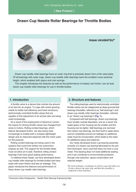
<strong>Drawn</strong> <strong>Cup</strong> <strong>Needle</strong> <strong>Roller</strong> <strong>Bearings</strong> <strong>for</strong> <strong>Throttle</strong> <strong>Bodies</strong><br />
Hideki AKAMATSU<br />
<strong>Drawn</strong> cup needle roller bearings have an outer ring that is precisely drawn from a thin steel plate.<br />
Of all bearings with outer rings, drawn cup needle roller bearings have the smallest cross sectional<br />
height, which enables both space and cost savings.<br />
This chapter introduces the features as well as the per<strong>for</strong>mance of sealed, low friction, low air leak<br />
drawn cup needle roller bearings <strong>for</strong> use in throttle bodies.<br />
1. Introduction<br />
A throttle valve is a device that controls the amount<br />
of air fed into an engine. To cope with recent growing<br />
needs <strong>for</strong> better fuel efficiency and lower emissions,<br />
electronically controlled throttle valves that are<br />
capable of fine adjustment of an air/fuel ratio are being<br />
used increasingly.<br />
As a result of the employment of electronic control,<br />
the means <strong>for</strong> driving throttle valves has changed from<br />
wires to motors. Rolling contact bearings, which<br />
feature decreased friction, are also being used<br />
increasingly to enable both a compact lightweight<br />
design and an improved response with the motor used<br />
<strong>for</strong> this purpose.<br />
Rolling contact bearings are being used in the<br />
systems that control the airflow into automotive<br />
engines as well. The support <strong>for</strong> the throttle blade<br />
must not allow air to leak, there<strong>for</strong>e rolling contact<br />
bearings must have good sealing per<strong>for</strong>mance.<br />
To address these needs, we have developed drawn<br />
cup needle roller bearings <strong>for</strong> throttle bodies that have<br />
seals with lower friction and less air leakage. This<br />
paper introduces the features and per<strong>for</strong>mance of<br />
these drawn cup needle roller bearings.<br />
2. Structure and features<br />
The rolling bearings used <strong>for</strong> electronically controlled<br />
throttle valves can be categorized as deep grooved ball<br />
bearings (hereafter, referred to as "ball bearings") and<br />
drawn cup needle roller bearings (hereafter, referred<br />
to as "drawn cup bearings") (Fig. 1).<br />
Compared with ball bearings, drawn cup bearings<br />
have smaller outside diameters, and as a result, the<br />
radial space of the housing can be smaller and the<br />
housing can be lighter. Ball bearings are narrower<br />
than drawn cup bearings, but their built-in seals alone<br />
cannot completely prevent air leakage so additional<br />
seals must be incorporated, which leads to the need<br />
<strong>for</strong> additional space and expense.<br />
Our newly developed drawn cup bearing assembly<br />
consists of a drawn cup bearing fabricated by the prebent<br />
technique* and a seal that does not have a core<br />
metal. This bearing does not need additional sealing,<br />
and it can contribute to environmental protection<br />
through cost reduction, space conservation and<br />
reduced weight.<br />
*Pre-bent technique: a technique in which a cage and rollers are<br />
fit into a drawn cup outer ring, and then the assembly is<br />
subjected to heat treatment.<br />
Automotive Sales Headquarters<br />
<strong>Needle</strong> <strong>Roller</strong> <strong>Bearings</strong> Engineering Dept.<br />
-76-
<strong>Drawn</strong> <strong>Cup</strong> <strong>Needle</strong> <strong>Roller</strong> <strong>Bearings</strong> <strong>for</strong> <strong>Throttle</strong> <strong>Bodies</strong><br />
<strong>Throttle</strong> blade<br />
Return spring<br />
<strong>Throttle</strong> blade<br />
Return spring<br />
Separate seal<br />
Motor<br />
Motor<br />
<strong>Drawn</strong> cup bearing<br />
(w/ built-in seal)<br />
Control gearing<br />
Deep groove<br />
ball bearing<br />
Control gearing<br />
<strong>Drawn</strong> cup bearing application example<br />
Deep groove ball bearing application example<br />
Fig. 1 Structure of electronic throttle bodies<br />
Table 1 Specification of drawn cup needle roller bearings<br />
<strong>for</strong> throttle bodies<br />
Fig. 2 Structure of drawn cup needle roller bearings<br />
<strong>for</strong> throttle bodies<br />
Development<br />
target Specifications<br />
Dimensions<br />
Outer ring<br />
Cage<br />
<strong>Roller</strong>s<br />
Seal<br />
Rated load<br />
<br />
Others<br />
Friction<br />
Air leakage<br />
Inscribed circle dia. 10outside dia. 14width 14 mm<br />
Chromium molybdenum steel<br />
V-type welded cage<br />
Crowned<br />
Fluorine rubber, no core metal<br />
Dynamic rated load Cr4500 N<br />
Static rated load C0r5100 N<br />
High per<strong>for</strong>mance grease applied<br />
1.1 N-cm max.<br />
0.8cm 3 /min. max.<br />
3. Friction Per<strong>for</strong>mance<br />
The friction per<strong>for</strong>mance of the bearings that<br />
support the throttle blade is a critical factor in adopting<br />
a compact design and achieving quick response with<br />
the motor.<br />
A friction measurement value is obtained by<br />
inserting a torque gauge with a shaft of a specified<br />
diameter into a drawn cup bearing that is press-fitted<br />
into a standard ring, and turning the gauge 90<br />
degrees. The friction value of these bearings is<br />
approximately 0.8 N-cm, which is sufficiently lower<br />
than the development target of 1.1 N-cm (Table 2)<br />
Table 2 Test result of friction<br />
Development target 1.1 N-cm max.<br />
Number of samples (n) 30 pcs.<br />
Mean value<br />
0.78 N-cm<br />
Max. value<br />
0.85 N-cm<br />
Min. value<br />
0.70 N-cm<br />
Standard deviation 0.054 N-cm<br />
-77-
<strong>NTN</strong> TECHNICAL REVIEW No.732005<br />
4. Air Leakage Prevention Per<strong>for</strong>mance<br />
Because the throttle valve regulates the amount of<br />
air fed into the engine, the amount of air leakage from<br />
the supports of the throttle blade must be strictly<br />
controlled.<br />
The measuring method and resultant<br />
measurements of the air leakage on drawn cup<br />
bearings are summarized below.<br />
Be<strong>for</strong>e starting the air leakage measurements, each<br />
drawn cup bearing was press-fit into a ring of specified<br />
dimensions, and the shaft was inserted into the<br />
bearing of a specified diameter. This set was then<br />
mounted to a sufficiently rigid measuring head. The<br />
other measuring head was shut with a lid, and was<br />
used as a standard control. These heads were<br />
connected to an air leakage tester, the open space in<br />
each head was adjusted to a negative pressure, and<br />
then air leakage was measured. Photo 1 shows the<br />
air leakage tester, and Fig. 3 illustrates the<br />
measurement heads.<br />
The amount of air leakage with our drawn cup<br />
bearing was 0.01 cm 3 /min. or lower, which is<br />
sufficiently lower than the development target of 0.8<br />
cm 3 /min (Table 3).<br />
Suction<br />
Suction<br />
Bearing<br />
No.<br />
No.1<br />
No.2<br />
No.3<br />
No.4<br />
Negative<br />
pressure<br />
Fig. 3 Measurement part<br />
Table 3 Test result of air leakage<br />
Diameter of shaft<br />
inserted (mm)<br />
9.975<br />
5. Conclusion<br />
Standard control<br />
Test bearing<br />
Atmospheric<br />
pressure<br />
Air leakage<br />
Development target: 0.8 cm 3 /min. max.<br />
0.01cm 3 /min. max.<br />
0.01cm 3 /min. max.<br />
0.01cm 3 /min. max.<br />
0.01cm 3 /min. max.<br />
This paper has introduced our unique drawn cup<br />
bearing assembly <strong>for</strong> a throttle valve. This assembly<br />
incorporates a compact, less expensive drawn cup<br />
bearing and a seal that features lower friction and air<br />
leakage prevention capabilities. Use of this bearing<br />
helps reduce the size of the throttle valve and improve<br />
the response speed. We believe that this bearing will<br />
offer better control of air-fuel ratios <strong>for</strong> automotive<br />
engines, helping realize better fuel efficiency and<br />
lower emissions and thus contributing to global<br />
environmental protection.<br />
Photo 1 Air leakage tester<br />
Photos of author<br />
Hideki AKAMATSU<br />
Automotive Sales Headquraters<br />
<strong>Needle</strong> <strong>Roller</strong> <strong>Bearings</strong><br />
Engineering Dept.<br />
-78-
![[New Product] Unit Products for Office Equipment - NTN](https://img.yumpu.com/27154451/1/184x260/new-product-unit-products-for-office-equipment-ntn.jpg?quality=85)
![[New Product] Development of Oil-impregnated Sintered ... - NTN](https://img.yumpu.com/27154427/1/184x260/new-product-development-of-oil-impregnated-sintered-ntn.jpg?quality=85)