Repair System for Sixth and Seventh Generation LCD Color ... - NTN
Repair System for Sixth and Seventh Generation LCD Color ... - NTN
Repair System for Sixth and Seventh Generation LCD Color ... - NTN

Create successful ePaper yourself
Turn your PDF publications into a flip-book with our unique Google optimized e-Paper software.
<strong>NTN</strong> TECHNICAL REVIEW No.722004<br />
New Product <br />
<strong>Repair</strong> <strong>System</strong> <strong>for</strong> <strong>Sixth</strong> <strong>and</strong> <strong>Seventh</strong> <strong>Generation</strong><br />
<strong>LCD</strong> <strong>Color</strong> Filters<br />
Akihiro YAMANAKA<br />
Akira MATSUSHIMA<br />
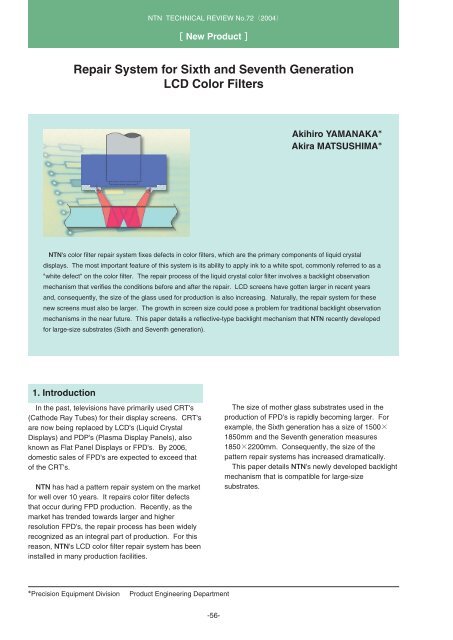
<strong>NTN</strong>'s color filter repair system fixes defects in color filters, which are the primary components of liquid crystal<br />
displays. The most important feature of this system is its ability to apply ink to a white spot, commonly referred to as a<br />
"white defect" on the color filter. The repair process of the liquid crystal color filter involves a backlight observation<br />
mechanism that verifies the conditions be<strong>for</strong>e <strong>and</strong> after the repair. <strong>LCD</strong> screens have gotten larger in recent years<br />
<strong>and</strong>, consequently, the size of the glass used <strong>for</strong> production is also increasing. Naturally, the repair system <strong>for</strong> these<br />
new screens must also be larger. The growth in screen size could pose a problem <strong>for</strong> traditional backlight observation<br />
mechanisms in the near future. This paper details a reflective-type backlight mechanism that <strong>NTN</strong> recently developed<br />
<strong>for</strong> large-size substrates (<strong>Sixth</strong> <strong>and</strong> <strong>Seventh</strong> generation).<br />
1. Introduction<br />
In the past, televisions have primarily used CRT's<br />
(Cathode Ray Tubes) <strong>for</strong> their display screens. CRT's<br />
are now being replaced by <strong>LCD</strong>'s (Liquid Crystal<br />
Displays) <strong>and</strong> PDP's (Plasma Display Panels), also<br />
known as Flat Panel Displays or FPD's. By 2006,<br />
domestic sales of FPD's are expected to exceed that<br />
of the CRT's.<br />
<strong>NTN</strong> has had a pattern repair system on the market<br />
<strong>for</strong> well over 10 years. It repairs color filter defects<br />
that occur during FPD production. Recently, as the<br />
market has trended towards larger <strong>and</strong> higher<br />
resolution FPD's, the repair process has been widely<br />
recognized as an integral part of production. For this<br />
reason, <strong>NTN</strong>'s <strong>LCD</strong> color filter repair system has been<br />
installed in many production facilities.<br />
The size of mother glass substrates used in the<br />
production of FPD's is rapidly becoming larger. For<br />
example, the <strong>Sixth</strong> generation has a size of 1500<br />
1850mm <strong>and</strong> the <strong>Seventh</strong> generation measures<br />
18502200mm. Consequently, the size of the<br />
pattern repair systems has increased dramatically.<br />
This paper details <strong>NTN</strong>'s newly developed backlight<br />
mechanism that is compatible <strong>for</strong> large-size<br />
substrates.<br />
Precision Equipment Division<br />
Product Engineering Department<br />
-56-
<strong>Repair</strong> <strong>System</strong> <strong>for</strong> <strong>Sixth</strong> <strong>and</strong> <strong>Seventh</strong> <strong>Generation</strong> <strong>LCD</strong> <strong>Color</strong> Filters<br />
2. Backlight mechanism<br />
<strong>for</strong> <strong>LCD</strong> CF repair system<br />
As shown in Fig. 1, an <strong>LCD</strong> panel is made up of<br />
TFT <strong>and</strong> CF substrates bonded together with spacer<br />
balls <strong>and</strong> filled with liquid crystal <strong>and</strong> a backlight at the<br />
bottom of this structure. A CF glass substrate has red<br />
(R), green (G), <strong>and</strong> blue (B) pixels arranged in a<br />
matrix <strong>for</strong>mat (see Fig. 2).<br />
Seal<br />
Polarizing<br />
plate<br />
<strong>Color</strong> filter<br />
(CF) layer<br />
CF substrate(glass)<br />
TFT substrate (glass)<br />
Viewing direction<br />
Spacer<br />
Common<br />
electrode (ITO)<br />
Seal<br />
pixel. Black defects are caused when colors are<br />
mixied on a pixel or dust adheres to a pixel. They<br />
may be repaired by first removing them by laser<br />
cutting followed by coating them with ink of the same<br />
color.<br />
2.1 Evolution of CF repair system configuration<br />
As mentioned be<strong>for</strong>e, the size of FPD's is<br />
increasing at an amazing rate. In response, the size<br />
<strong>and</strong> the configuration of the repair systems are also<br />
changing rapidly. The primary purpose <strong>for</strong> the<br />
changes is to limit the necessary floor space <strong>for</strong> the<br />
system inside clean rooms.<br />
Fig. 3 shows the evolution of the CF system<br />
configurations.<br />
<strong>Repair</strong> head<br />
Polarizing plate Liquid crystal TFT Pixel electrode<br />
layer<br />
Light<br />
Backlight<br />
Fig.1 <strong>LCD</strong> structure<br />
Glass substrate<br />
Y axis<br />
X axis<br />
A CF substrate adds color in<strong>for</strong>mation to light <strong>and</strong> is<br />
turned "on" or "off" by the liquid crystal. Light going<br />
through the CF substrate will display the color<br />
in<strong>for</strong>mation <strong>for</strong> that pixel: enabling an <strong>LCD</strong> to display<br />
color images.<br />
As described above, a CF substrate functions by<br />
allowing light to pass through it. Consequently, a CF<br />
substrate repair system must have a backlight<br />
mechanism to verify the quality of the repair.<br />
A CF repair system is equipment that is designed to<br />
repair defects on CF panels as shown in Fig. 2.<br />
White defects are spots on pixels where color is<br />
missing. These defects are repaired by coating the<br />
white spot with ink of the same color as the rest of the<br />
a. Third <strong>and</strong> earlier generations<br />
X axis<br />
<strong>Repair</strong> head<br />
Glass substrate<br />
Y axis<br />
b. Fourth <strong>and</strong> Fifth generations<br />
Y axis<br />
<strong>Repair</strong> head<br />
Glass substrate<br />
X axis<br />
White<br />
defect<br />
Black<br />
defect<br />
c. <strong>Sixth</strong> <strong>and</strong> future generations<br />
Fig.3 Transition in the construction of repair systems<br />
related to generation change of <strong>LCD</strong> substrate<br />
Fig.2 Defects in a CF panel<br />
-57-
<strong>NTN</strong> TECHNICAL REVIEW No.722004<br />
In the repair system configurations <strong>for</strong> Third <strong>and</strong><br />
earlier generations, substrates were placed on the XY<br />
tables. The tables moved horizontally while the repair<br />
heads were fixed. The systems <strong>for</strong> the Fourth <strong>and</strong><br />
Fifth generations generally had separate tables <strong>for</strong> the<br />
X-axis <strong>and</strong> the Y-axis <strong>and</strong> the substrates were moved<br />
in one axis while the repair head was moved in the<br />
other.<br />
Most of the <strong>Sixth</strong> <strong>and</strong> <strong>Seventh</strong> generation repair<br />
systems secures substrates in a fixed position <strong>and</strong><br />
employs the gantry method which moves the repair<br />
head in both the X <strong>and</strong> Y directions.<br />
2.2 Traditional backlight mechanism <strong>and</strong> its<br />
Issues<br />
The backlight mechanism, as shown in Fig. 4,<br />
illuminates the back of the surface plate so the light<br />
transmitted through the CF substrate can be<br />
observed. For this reason, the support <strong>for</strong> the CF<br />
substrate needs to be transparent. There<strong>for</strong>e, most<br />
surface plates are made out of glass.<br />
Y axis<br />
X axis<br />
<strong>Repair</strong> head<br />
Y axis<br />
X axis<br />
Linear guide<br />
Linear guide<br />
Backlight<br />
Linear guide<br />
a. XY moving backlight system<br />
Y axis<br />
X axis<br />
<strong>Repair</strong> head<br />
Linear guide<br />
Y axis<br />
<strong>Repair</strong> head<br />
Linear guide<br />
Backlight<br />
b. Y moving backlight system<br />
CF substrate<br />
Fig.5 Conventional backlight mechanism<br />
Glass surface plate<br />
Backlight<br />
Fig.4 Glass surface plate<br />
The gantry method used in the <strong>Sixth</strong> <strong>and</strong> the<br />
<strong>Seventh</strong>-generation systems moves the repair head in<br />
both X <strong>and</strong> Y directions. It requires a synchronized<br />
movement of the backlight mechanism. This results in<br />
a very complex system construction. Fig. 5 shows the<br />
backlight mechanism that has been adopted <strong>for</strong> the<br />
traditional gantry method. Fig. 5-a shows the complex<br />
structure of the backlight mechanism that moves<br />
synchronously with the repair head in X <strong>and</strong> Y<br />
directions.<br />
Fig. 5-b is a simpler design in terms of both its<br />
structure <strong>and</strong> control where the linear backlight moves<br />
synchronously with the repair head in a single axis.<br />
This design does not require any additional control<br />
mechanism <strong>and</strong> is used in many systems. However,<br />
this method presents many system configuration<br />
issues when it comes to meeting the needs of <strong>Sixth</strong><br />
<strong>and</strong> <strong>Seventh</strong> generation FPD's. Also, it is difficult to<br />
build backlight mechanisms <strong>for</strong> increasingly larger<br />
systems with this design.<br />
In the configurations illustrated in Figs. 5-a <strong>and</strong> 5-b,<br />
the light source of the backlight moves underneath the<br />
glass surface plate on which CF substrates are<br />
placed. This means that support members must be<br />
located at the perimeter of the glass surface plate.<br />
To accommodate larger <strong>Sixth</strong> <strong>and</strong> <strong>Seventh</strong><br />
generation FPD substrates, the size of glass surface<br />
plate must increase. However, as mentioned above,<br />
the glass surface plate must be supported at its<br />
perimeter. There<strong>for</strong>e, the weight of the glass surface<br />
plate can cause deflection in the glass. Also, impact<br />
during transportation of the system can damage the<br />
glass surface plate.<br />
The glass surface plate needs to have a mechanism<br />
<strong>for</strong> securing the CF substrate in position. Today,<br />
many systems use vacuum suction mechanisms <strong>for</strong><br />
this purpose. The vacuum suction mechanism<br />
requires suction grooves to be cut <strong>and</strong> holes to be<br />
drilled on the glass surface plate. It also requires<br />
piping to be placed on the back of the glass surface<br />
plate. The suction holes <strong>and</strong> piping can obstruct the<br />
backlight.<br />
-58-
<strong>Repair</strong> <strong>System</strong> <strong>for</strong> <strong>Sixth</strong> <strong>and</strong> <strong>Seventh</strong> <strong>Generation</strong> <strong>LCD</strong> <strong>Color</strong> Filters<br />
When placing a CF substrate onto a repair system,<br />
a transfer device normally is used. Today, robots are<br />
used as transfer devices most of the time.<br />
Lift mechanisms need to be installed on the repair<br />
systems so that they can receive the CF substrates<br />
transferred by the robots. A typical lift mechanism<br />
used <strong>for</strong> such an application is shown in Fig. 6. The<br />
lift mechanism raises the lifter pins to receive the<br />
substrate from the robot, <strong>and</strong> then lowers the lifter<br />
pins to place the substrate on the glass surface plate.<br />
Holes must be drilled into the glass surface plate, as<br />
shown in Fig. 6, so the lifter pins can pass through.<br />
These holes affect the function of the backlight.<br />
These are the major issues currently affecting the<br />
present backlight mechanism. At this time, the<br />
strength of the glass surface plate is the biggest issue.<br />
Robot h<strong>and</strong><br />
CF substrate<br />
Glass surface plate<br />
Fig.6 Lift mechanism<br />
Lifter pin<br />
Drive motor<br />
Lift<br />
3. New backlight mechanism<br />
In order to improve the function of the repair<br />
system, <strong>NTN</strong> has developed a new backlight<br />
mechanism. Instead of lighting from underneath the<br />
repair head, the new mechanism lights from the top of<br />
the repair head side to <strong>for</strong> improved inspection. With<br />
this configuration, since the source of the backlight is<br />
no longer located underneath the surface plate, the<br />
plate can be supported along its entire surface.<br />
3.1 Outline of reflective type backlight<br />
mechanism<br />
Fig. 7 shows a diagram of the new backlight<br />
mechanism (reflective type).<br />
The reflective-type backlight mechanism has a ring<br />
lamp around the objective lens of the repair head.<br />
Light is irradiated from around the observation point,<br />
utilizing the translucency of a CF substrate. The light<br />
is then reflected off the mirror surface on the backside<br />
of the glass surface plate, re-entering the CF<br />
substrate from the backside, thereby providing<br />
backlight <strong>for</strong> the lens.<br />
Let us now explain the potential issues <strong>and</strong><br />
corresponding solutions <strong>for</strong> backlight observation<br />
using this method.<br />
Objective lens<br />
Ring lamp<br />
Converging lens<br />
Incident light<br />
CF substrate<br />
Reflective light<br />
Mirror finish<br />
Glass surface<br />
plate<br />
Fig.7 Reflective-type backlight mechanism<br />
1 Securing reflective light intensity<br />
¡Irradiation angle of light<br />
Since there is a constraint on the arrangement of<br />
the ring lamp with respect to interference with the<br />
objective lens, the angle of the incident light to the<br />
CF substrate was set at 30˚. Light emitted by the<br />
ring lamp spreads out to about 30˚. A ring lens<br />
was installed at the light emitter to improve the light<br />
convergence, thus increasing the utilization of the<br />
light from the ring lamp <strong>and</strong> increasing the<br />
reflective light intensity. Without these measures,<br />
the spreading light from the ring lamp reaches the<br />
-59-
<strong>NTN</strong> TECHNICAL REVIEW No.722004<br />
observation point <strong>and</strong> prevents clear observation<br />
images from <strong>for</strong>ming.<br />
¡Thickness of glass surface plate<br />
In order to reflect the incident light from the ring<br />
lamp onto the mirror surface <strong>and</strong> then back onto<br />
observation point, the glass surface has to be a<br />
specified thickness. As shown in Fig. 8-a, if the<br />
glass surface plate is too thin, the reflected light<br />
does not reach the back surface of the observation<br />
point <strong>and</strong> cannot backlight observation images<br />
cannot be <strong>for</strong>med.<br />
The test results indicate that if the glass surface<br />
plate has a thickness of 15mm or greater (Fig. 8-<br />
b), it can direct the reflected light from the mirror<br />
surface onto the backside of the observation point.<br />
The tests also found that this backlight observation<br />
was as good as that with a traditional backlight<br />
mechanism.<br />
<br />
<br />
<br />
Fig.8 Influence of glass plate thickness - 1<br />
(Backlight intensity)<br />
2 Solution to impacts of laser cutting<br />
As mentioned above, black defects on CF’s can be<br />
repaired by cutting them with a laser <strong>and</strong> then<br />
coating them with ink. The laser cutting could cut<br />
the mirror on the back of the glass surface plate.<br />
As shown in Fig. 9-a, if the thickness (t) of the<br />
glass surface plate is small, then the diameter of<br />
laser convergence (D) on the mirror surface is<br />
small <strong>and</strong> the power density of laser is high. In this<br />
situation, the mirror surface is vulnerable to<br />
damage by the laser.<br />
The test results indicate that, if the thickness of the<br />
glass surface plate is 12 mm or greater, as shown<br />
in Fig. 9-b, then the diameter of laser convergence<br />
(D) on the mirror surface is large <strong>and</strong> the laser<br />
power density is low. Consequently, the mirror<br />
surface should not sustain any damage during<br />
laser cutting.<br />
<br />
Laser beam<br />
a<br />
<br />
b<br />
Fig.9 Influence of glass plate thickness - 2<br />
(Damage on mirror by cutting laser)<br />
3 Separation from incident light observation<br />
As the ring lens prevents light from entering the<br />
observation point, the incident light does not affect the<br />
observed images. However, it is possible <strong>for</strong> the<br />
incident light emitted by the objective lens to be<br />
reflected by the mirror on the bottom of the surface<br />
plate <strong>and</strong> impact the observation images.<br />
As shown in Fig. 10 (a), if the thickness (t) of the<br />
glass surface plate is small, then the diameter (D) of<br />
light reflecting off the mirror surface <strong>and</strong> entering the<br />
back of the observation point is small <strong>and</strong> the light<br />
density is high. If this occurs, the light that is reflected<br />
on the image affects the transmitted light.<br />
The test results indicate that, if the thickness (t) of<br />
the glass surface plate is 5 mm or greater, as shown<br />
in Fig. 10-b, then the diameter (D) of light reflecting<br />
off the mirror surface <strong>and</strong> entering the back of the<br />
observation point is large <strong>and</strong> the light density is low.<br />
When this occurs, reflection on the mirror surface<br />
does not affect the observed image.<br />
Incident light<br />
Reflected<br />
light<br />
a<br />
<br />
<br />
<br />
Laser beam<br />
Incident light<br />
Reflected<br />
light<br />
b<br />
<br />
<br />
Fig.10 Influence of glass plate thickness - 3<br />
(Reflection of incident light)<br />
<br />
<br />
-60-
<strong>Repair</strong> <strong>System</strong> <strong>for</strong> <strong>Sixth</strong> <strong>and</strong> <strong>Seventh</strong> <strong>Generation</strong> <strong>LCD</strong> <strong>Color</strong> Filters<br />
4 Solution to lifter pinhole issue<br />
The glass surface plate must have holes <strong>for</strong> the<br />
lifter pins to pass through <strong>for</strong> loading <strong>and</strong> unloading<br />
CF substrates. Since these holes must pass through<br />
the entire plate, a mirror cannot be installed on the<br />
back of the glass surface plate at these locations. As<br />
a result, light cannot be reflected at these holes <strong>and</strong><br />
an image cannot be observed.<br />
To resolve this issue, optical fibers were installed<br />
inside the lifter pins as shown in Fig. 11. This<br />
measure successfully resolved the issue <strong>and</strong> made<br />
backlight observation at the lifter pinholes possible.<br />
6 Solution to electrostatic charge<br />
Electrostatic charge is produced by the contact <strong>and</strong><br />
separation of the glass surface plate <strong>and</strong> the CF<br />
substrate <strong>and</strong> is a common issue <strong>for</strong> all backlight<br />
mechanisms. Solutions to this issue were studied as<br />
a part of this development.<br />
As mentioned above, electrostatic charge occurs<br />
due to the contact <strong>and</strong> separation of the glass surface<br />
plate <strong>and</strong> the CF substrate. Minimizing the contact<br />
area between the plate <strong>and</strong> the substrate should<br />
reduce the amount of electrostatic charge. As a<br />
result, a special surface texture was used <strong>for</strong> the top<br />
of the glass surface plate (see Fig. 13).<br />
Light<br />
Lifter pin<br />
Lighting optical fiber<br />
Lifter pin hole<br />
Fig.11 Lighting of lifter pin holes<br />
5 Solution to vacuum hole issue<br />
Vacuum holes must be made on the glass surface<br />
plate to secure CF substrates. Like the lifter pinholes,<br />
these holes must pass through the entire plate so no<br />
mirror process can be applied at the bottom.<br />
However, if the hole diameter is small enough, shown<br />
in Fig. 12, backlight observation is possible by the<br />
light reflected by the mirror surface around these<br />
holes.<br />
The reflected light at the center of the vacuum hole<br />
is refracted by the wall of the hole, distorting the<br />
backlight observation image compared to the ordinary<br />
surface. This distortion in the images was reduced by<br />
optimizing the distance between the ring lamp <strong>and</strong> the<br />
CF substrate.<br />
CF substrate<br />
Special processing<br />
Glass surface plate<br />
Fig.13 Glass plate surface special processing<br />
Special processing makes micro dents <strong>and</strong> bumps<br />
on the top of the glass surface plate. This special<br />
process reduces the contact area between the glass<br />
surface plate <strong>and</strong> the CF substrate, thereby reducing<br />
the occurrence of electrostatic charge compared with<br />
a regular glass surface. Furthermore, light entering<br />
from the back surface of the CF substrate is dispersed<br />
by the micro dents <strong>and</strong> bumps created by the special<br />
process. As a side benefit, this dispersion increases<br />
the brightness of the backlight observation image.<br />
Vacuum hole<br />
Fig.12 Lighting of vacuum holes<br />
-61-
<strong>NTN</strong> TECHNICAL REVIEW No.722004<br />
7 Solution to judgment time<br />
The repair judgment is an important issue with<br />
repair systems. In the preceding discussion about<br />
reflective-type backlight mechanisms, the ring lighting<br />
was examined. The ring lighting has the following<br />
problems.<br />
Most of the current systems offer multiple objective<br />
lenses that are exchanged by the rotational movement<br />
controlled by the revolver mechanism. Since the<br />
revolver mechanism rotates the objective lenses, the<br />
ring lamp must retreat during the rotation. This retreat<br />
time must be included in the total judgment time. It<br />
may only take a few seconds, but any additional<br />
judgment time should not be accepted.<br />
The objective of this study was to determine a<br />
lighting layout that does not require the ring lamp to<br />
retreat during objective lens exchanges <strong>and</strong> that<br />
provides sufficient light intensity <strong>for</strong> backlight<br />
observation.<br />
The study concluded that multiple arc-type lamps<br />
could achieve this objective. These lamps were made<br />
by dividing a ring lamp in sections to avoid<br />
interference with the objective lenses during their<br />
rotation.<br />
Photo 1 shows the backlight observation images<br />
obtained using the reflective-type backlight<br />
mechanism. The images are as good as those of the<br />
traditional backlight mechanism.<br />
Photo 1 Image of CF pattern with reflective type<br />
backlight<br />
8 Meeting the needs of the <strong>Sixth</strong> <strong>and</strong> <strong>Seventh</strong><br />
generation FPD’s<br />
Unlike the traditional backlight method, the reflective<br />
type backlight method accommodates support<br />
mechanisms under the glass surface plate.<br />
There<strong>for</strong>e, there would be no structural problem as the<br />
system becomes larger.<br />
Considering all the above issues, the specifications<br />
of a reflective type backlight mechanism were<br />
determined as shown in Table 1.<br />
Table 1 Reflective-type backlight mechanism<br />
specifications<br />
Size of glass<br />
surface plate<br />
<strong>Sixth</strong> generation<br />
<strong>Seventh</strong> generation<br />
15401890 mm<br />
19102240 mm<br />
Thickness of glass surface<br />
plate<br />
Distance between reflective<br />
light <strong>and</strong> CF substrate<br />
Surface processing of<br />
glass surface plate<br />
Back surface processing<br />
of glass surface plate<br />
Reflective light<br />
t=19 mm<br />
W.D.=18 mm<br />
Special processing<br />
Mirror processing<br />
Divided arc lighting<br />
-62-
<strong>Repair</strong> <strong>System</strong> <strong>for</strong> <strong>Sixth</strong> <strong>and</strong> <strong>Seventh</strong> <strong>Generation</strong> <strong>LCD</strong> <strong>Color</strong> Filters<br />
4. Conclusion<br />
This paper introduced a new backlight mechanism<br />
<strong>for</strong> the CF repair system. The objective of the new<br />
backlight mechanism was to meet the requirements of<br />
<strong>Sixth</strong> <strong>and</strong> Senventh generation FPD's. However, FPD<br />
manufacturers have concepts of even larger mother<br />
glass substrates. As described earlier, a backlight<br />
mechanism is a necessity <strong>for</strong> repairing color filters <strong>and</strong><br />
the traditional backlight mechanism would face<br />
structural problems when dealing with increasingly<br />
large glass substrates. The reflective-type backlight<br />
mechanism has resolved any structural issues<br />
associated with the repair of large CF's substrate.<br />
This mechanism is a new feature of <strong>NTN</strong>'s CF repair<br />
systems. This paper primary focused on backlight<br />
mechanism, but as glass substrates become larger,<br />
numerous new issues will continue to challenge<br />
equipment manufacturers. <strong>NTN</strong> will continue<br />
developing our repair system components to solve<br />
these new issues to improve the innovation <strong>and</strong><br />
quality of our products.<br />
Photos of authors<br />
Akihiro YAMANAKA<br />
Precision Equipment Division<br />
Product Engineering Dept.<br />
Akira MATSUSHIMA<br />
Precision Equipment Division<br />
Product Engineering Dept.<br />
-63-

![[New Product] Unit Products for Office Equipment - NTN](https://img.yumpu.com/27154451/1/184x260/new-product-unit-products-for-office-equipment-ntn.jpg?quality=85)
![[New Product] Development of Oil-impregnated Sintered ... - NTN](https://img.yumpu.com/27154427/1/184x260/new-product-development-of-oil-impregnated-sintered-ntn.jpg?quality=85)