KISS-102 Data Sheet 8-26 - Process Support Products
KISS-102 Data Sheet 8-26 - Process Support Products
KISS-102 Data Sheet 8-26 - Process Support Products

Create successful ePaper yourself
Turn your PDF publications into a flip-book with our unique Google optimized e-Paper software.
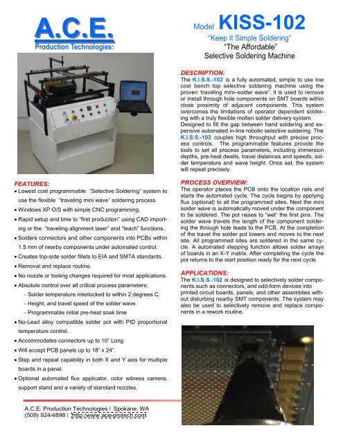
Model <strong>KISS</strong>-<strong>102</strong><br />
“Keep It Simple Soldering”<br />
“The Affordable”<br />
Selective Soldering Machine<br />
DESCRIPTION:<br />
The K.I.S.S.-<strong>102</strong> is a fully automated, simple to use low<br />
cost bench top selective soldering machine using the<br />
proven ‘traveling mini–solder wave”. It is used to remove<br />
or install through hole components on SMT boards within<br />
close proximity of adjacent components. This system<br />
overcomes the limitations of operator dependent soldering<br />
with a truly flexible molten solder delivery system.<br />
Designed to fill the gap between hand soldering and expensive<br />
automated in-line robotic selective soldering. The<br />
K.I.S.S.-<strong>102</strong> couples high throughput with precise process<br />
controls. The programmable features provide the<br />
tools to set all process parameters, including immersion<br />
depths, pre-heat dwells, travel distances and speeds, solder<br />
temperature and wave height. Once set, the system<br />
will repeat precisely.<br />
FEATURES:<br />
Lowest cost programmable “Selective Soldering” system to<br />
use the flexible “traveling mini wave” soldering process.<br />
Windows XP O/S with simple CNC programming.<br />
Rapid setup and time to “first production” using CAD importing<br />
or the “traveling alignment laser” and “teach” functions.<br />
Solders connectors and other components into PCBs within<br />
1.5 mm of nearby components under automated control.<br />
Creates top-side solder fillets to EIA and SMTA standards.<br />
Removal and replace routine.<br />
No nozzle or tooling changes required for most applications.<br />
Absolute control over all critical process parameters:<br />
- Solder temperature interlocked to within 2 degrees C.<br />
- Height, and travel speed of the solder wave.<br />
- Programmable initial pre-heat soak time<br />
No-Lead alloy compatible solder pot with PID proportional<br />
temperature control.<br />
Accommodates connectors up to 10” Long<br />
Will accept PCB panels up to 18” x 24”.<br />
Step and repeat capability in both X and Y axis for multiple<br />
boards in a panel.<br />
Optional automated flux applicator, color witness camera,<br />
support stand and a variety of standard nozzles.<br />
PROCESS OVERVIEW:<br />
The operator places the PCB onto the location rails and<br />
starts the automated cycle. The cycle begins by applying<br />
flux (optional) to all the programmed sites. Next the mini<br />
solder wave is automatically moved under the component<br />
to be soldered. The pot raises to “wet” the first pins. The<br />
solder wave travels the length of the component soldering<br />
the through hole leads to the PCB. At the completion<br />
of the travel the solder pot lowers and moves to the next<br />
site. All programmed sites are soldered in the same cycle.<br />
A automated stepping function allows solder arrays<br />
of boards in an X-Y matrix. After completing the cycle the<br />
pot returns to the start position ready for the next cycle.<br />
APPLICATIONS:<br />
The K.I.S.S.-<strong>102</strong> is designed to selectively solder components<br />
such as connectors, and odd-form devices into<br />
printed circuit boards, panels, and other assemblies without<br />
disturbing nearby SMT components. The system may<br />
also be used to selectively remove and replace components<br />
in a rework routine.<br />
A.C.E. Production Technologies l Spokane, WA<br />
(509) 924-4898 l http:/www.ace-protech.com
SOLDER POT:<br />
The solder pot wetted surfaces are constructed of specially<br />
treated 316 stainless steel able to withstand aggressive<br />
no-lead solders. The heaters are sized to bring<br />
the solder safely to temperature within 30 minutes. Recirculation<br />
of solder is accomplished via a speedcontrolled<br />
motor coupled to a treated stainless steel impeller<br />
assembly. The solder distribution system is designed<br />
to minimize dross build up while providing an extremely<br />
consistent and repeatable solder wave shape.<br />
A nitrogen blanket captured within the enclosed solder<br />
pot inerts the molten solder surfaces minimizing dross.<br />
The nitrogen escapes surrounding the solder nozzle and<br />
PCB as the solder wave contacts the terminals functionally<br />
minimizing icicles and solder bridges while providing<br />
an inerted return of the solder from the nozzle back into<br />
the pot.<br />
The solder temperature is interlocked within ± 2°C of set<br />
point. The capacity of the solder pot ensures sufficient<br />
solder mass for even the largest assemblies.<br />
The nozzles are magnetically fixed and can be exchanged<br />
in seconds. Two spherical “bullet wave” nozzles<br />
are supplied with the system. These are sufficient for<br />
most applications. Additional standard and special purpose<br />
nozzles can easily be used enabling selective soldering<br />
of wide patterns (multiple rows) in close proximity<br />
to previously soldered components without danger of reflowing<br />
them.<br />
SET-UP:<br />
The initial programming is accomplished by one of two<br />
methods. At a desktop or on the machine PC, import the<br />
PCB CAD file and pick the start/stop positions for all devices<br />
to be soldered. The process path and script is automatically<br />
created for you. Circular or angular interpolation<br />
allows soldering large round arrays in a spiral pattern and<br />
connectors not perpendicular to the X-Y plane.<br />
Optionally, use the top side laser pointer and joystick<br />
function to jog the solder pot/laser beam directly over the<br />
start and end of the row of terminals to be soldered.<br />
Teach these positions for all sites.<br />
Position the board in the location rails above the solder<br />
pot in contact with the adjustable “location fingers”.<br />
You can fine tune the X,Y and Z positions, speeds, solder<br />
wave height and other parameters to perfect the process.<br />
Start the cycle.<br />
OPTIONS:<br />
Matching support bench with storage shelf, casters and<br />
leveling feet<br />
Look-up witness camera with color LCD monitor<br />
Automated flux application system<br />
Additional solder nozzles (see data sheet)<br />
SPECIFICATIONS:<br />
PCB Panel Size<br />
Minimum<br />
Maximum<br />
2” x 2” 18” x 24”<br />
Motion<br />
Z-Axis Accuracy/Repeatability +/-.002"<br />
Speed 0-2 inches/sec<br />
Travel Distance = 1.5”<br />
X and X Axis Accuracy/Repeatability +/-.002"<br />
Speed 0-4 inches/sec<br />
Solder Pot<br />
Temperature Controller PID proportioning (0-350°C)<br />
± 2°C<br />
Solder Capacity 30 lbs.<br />
Pump<br />
PC controlled<br />
Controls<br />
Physical<br />
Dimensions<br />
Weight<br />
Facilities<br />
Power<br />
PC with Windows XP O.S.<br />
30" wide x 32" deep x 24" high<br />
275 lbs.<br />
120VAC/1 Ph/60 Hz<br />
15 amps<br />
Nitrogen consumption 15-50 CFH<br />
Air<br />
40-80 PSI with minimal consumption<br />
Exhaust Hood with 500 CFM recommended<br />
A.C.E. Production Technologies l Spokane, WA<br />
(509) 924-4898 l http:/www.ace-protech.com