QLCI IOM - TROX
QLCI IOM - TROX
QLCI IOM - TROX

You also want an ePaper? Increase the reach of your titles
YUMPU automatically turns print PDFs into web optimized ePapers that Google loves.
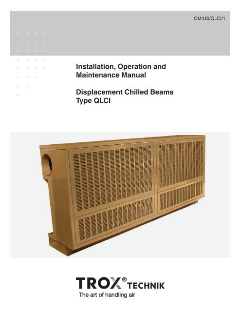
OM/US/<strong>QLCI</strong>/1<br />
Installation, Operation and<br />
Maintenance Manual<br />
Displacement Chilled Beams<br />
Type <strong>QLCI</strong>
Contents<br />
General Information<br />
1.1 Introduction 3<br />
1.2 Safety 3<br />
1.3 Symbols used in this manual 3<br />
1.4 Receiving, Inspection and Storage 3<br />
1.4 Damage reporting 3<br />
Product Description and Installation Preparation<br />
2.1 Product overview 4<br />
2.2 Construction description 4<br />
2.3 Application precautions 4<br />
2.4 Preparation for installation 4<br />
2.4 Items provided by installer 4<br />
2.4 Precautions 4<br />
Installation<br />
3.1 General procedure 5<br />
3.2 Installation considerations 5<br />
3.3 Hanging the chilled beam 5<br />
3.4 Air connections 6<br />
3.5 Water connections 6<br />
3.6 Flushing the water piping system 7<br />
3.7 Filling and venting the water system 7<br />
3.8 Typical installations 7<br />
Commissioning<br />
4.1 Waterside commissioning 8<br />
4.2 Airside commissioning 8<br />
4.3 Airside commissioning tables 8-9<br />
Maintenance<br />
5.1 Cleaning instructions 9<br />
5.2 Replacement parts 9<br />
Troubleshooting<br />
6.1 Symptoms & Solutions 10<br />
Warranties<br />
7.1 Representations and Warranties 11<br />
Special Note: <strong>QLCI</strong> terminals are intended for use in<br />
HVAC systems described in the <strong>QLCI</strong> catalog 1/7.2/US/1<br />
and covered under U.S. Patent 7,013,969.<br />
<strong>TROX</strong> USA, Inc.<br />
4305 Settingdown Circle<br />
Cumming, Georgia 30028<br />
Phone: 770.569.1433<br />
Fax: 770.569.1435<br />
E-Mail: trox@troxusa.com<br />
www.troxusa.com<br />
No part of this document may be reproduced in any form (by printing, photocopying or other means)<br />
or processed, duplicated or circulated electronically without prior written approval by <strong>TROX</strong> GmbH.<br />
© 2011 <strong>TROX</strong> GmbH<br />
All rights reserved.<br />
2<br />
<strong>QLCI</strong> displacement chilled beam Installation, Operation & Maintenance Manual (USA) (11/2011)
1 - General Information<br />
1.1 Introduction<br />
This installation, operation and maintenance manual is intended for<br />
<strong>QLCI</strong> displacment chilled beams.<br />
You must read all instructions prior to the installation, operation or<br />
maintenance of this product. Take special note of the information that<br />
is accompanied by the symbols described in section 1.3 below.<br />
<strong>TROX</strong> <strong>QLCI</strong> displacement chilled beams are designed to provide air<br />
quality and acoustical performance similar to conventional displacement<br />
systems, but are designed specifically for the North American<br />
climate. Units are fitted with a series of air induction nozzles that<br />
allow the supply of conventional air (50 to 55F) to the terminal.<br />
These nozzles induce room air through a cooling and/or reheat coil<br />
to pre-condition the air prior to mixing with the supply air jets. The<br />
result is a constant volume (variable temperature) displacement type<br />
supply of air to the space.<br />
The integral cooling coil within the unit is sized to allow the terminal<br />
to condition the room while the central system supplies air at (or<br />
near) the mandated space ventilation rate. Therefore, the central air<br />
handler can supply 100% outside air while all of the return air from<br />
the space is exhausted.<br />
The beam uses the primary air energy to induce air through the coil;<br />
it does not contain any moving parts, fans or motors.<br />
1.2 Safety<br />
The customer must use qualified personnel and follow all applicable<br />
building codes and safety regulations when installing, commissioning<br />
and performing maintenance of this product. Eye protection and<br />
gloves should be worn at all times when handling the product.<br />
Consult all local building, occupational safety and other codes applicable<br />
to the installation.<br />
Please pay particular attention to the symbols used throughout the<br />
manual that indicate safety related issues, warnings and important<br />
notices or information; read the complete manual before installation<br />
and be familiar with the meaning of the safety symbols in the next<br />
section 1.3.<br />
Fragile<br />
Handle with care. The chilled beam should not be<br />
handled using the water pipes or damage to the coil<br />
assembly may result!<br />
1.4 Receiving, Inspection and Storage<br />
All <strong>TROX</strong> products are inspected and tested prior to shipment to<br />
ensure the highest quality. <strong>QLCI</strong> units are packed individually in<br />
cardboard cartons.<br />
Upon receipt of the <strong>QLCI</strong> shipment, conduct a thorough inspection of<br />
the outer packaging and pallets for possible damage. If damage has<br />
occured during shipping, indicate the damaged items on the delivery<br />
papers immediately and inspect the <strong>QLCI</strong> units contained in those<br />
containers for damage.<br />
If damage has occurred during shipping, immediately file a claim with<br />
the carrier.<br />
Refer to the Manufacturer’s Representations and Warranties<br />
(included in each carton and on page 11 of this manual) for detailed<br />
handling instructions and damage reporting procedures.<br />
Note<br />
<strong>QLCI</strong> units should not be removed from its individual<br />
carton for storage. Do not unpack units until they<br />
have been moved to the installation location and just<br />
before installation is to begin (see details on pages<br />
4-7).<br />
Beams should be stored in a clean and dry location. If beams remain<br />
packaged as delivered (strapped and wrapped on pallet), they can<br />
be stored as delivered (do not stack pallets). If packaged beams are<br />
removed from pallet, they should not be stacked more than four high.<br />
Packaging is not suitable for outside storage.<br />
1.3 Symbols used in this manual<br />
When reading this manual, particular attention must be given to the<br />
parts marked with the following symbols:<br />
Warning!<br />
Indicates a potentially dangerous situation for the<br />
product and the environment<br />
!<br />
Important!<br />
Designation of a danger that can cause personal<br />
injury or damage to property.<br />
Note<br />
Indicates important notices or information<br />
<strong>QLCI</strong> displacement chilled beam Installation, Operation & Maintenance Manual (USA) (11/2011) 3
2 - Product Description/Installation Preparation<br />
2.1 Product overview<br />
<strong>QLCI</strong> displacement chilled beams are designed specifically for<br />
classroom applications. Units can operate in cooling or heating<br />
mode. In cooling mode, primary air is delivered through a series of<br />
induction nozzles. The relatively high velocity of air passing through<br />
the nozzles induces room air through the assembly’s return grille<br />
and across its integral heat exchanger coil. The air is reconditioned<br />
and then mixed with the primary air prior to being discharged back<br />
into the space via a grille mounted on the lower face of the <strong>QLCI</strong><br />
unit.<br />
<strong>TROX</strong> <strong>QLCI</strong> displacement chilled beams should be installed in the<br />
quantities, sizes and configurations shown on the project plans and<br />
schedules.<br />
2.2 Construction description<br />
The assembly (figure 1) of the <strong>QLCI</strong> consists of a heat transfer coil<br />
(2- or 4-pipe), primary air inlet (top or side), induction nozzles, telescoping<br />
connecting duct and condensate drip pan with connection.<br />
Units are housed within a cabinet (by <strong>TROX</strong> or by others) and<br />
optional accessories which include duct covers and MERV 8 filters.<br />
Figure 1<br />
Telescoping connection duct<br />
Heat Transfer Coil<br />
Condensate Pan<br />
Primary air inlet<br />
2.4 Preparation for installation<br />
!<br />
1.) <strong>QLCI</strong> displacement chilled beam unit is delivered by <strong>TROX</strong><br />
USA with:<br />
• Duct connections<br />
• A series of injection nozzles<br />
• Integral heat transfer coil<br />
• Perforated equalizing grille<br />
• Mounting brackets<br />
• Architectural cover/cabinet by <strong>TROX</strong><br />
2.) Installer to provide (according to all applicable building<br />
codes):<br />
• A mounting system including 2x4’s and all required hardware<br />
for installation<br />
• Hydronic piping system<br />
• Female ½˝ NPT fittings<br />
• Manual shut-off valve for each pipe run (recommended)<br />
• Flexible hoses for water connections from assembly to the<br />
supply and return water circuits (unless factory furnished<br />
flexible hoses are included with product order) or hard connections.<br />
3.) Precautions:<br />
Important!<br />
Installation is to be performed by properly trained<br />
and authorized personnel only! Read all instructions<br />
before beginning installation.<br />
Wall mounting<br />
brackets<br />
<strong>QLCI</strong>-CS WITH CABINET<br />
Condensate<br />
Connection<br />
!<br />
Important!<br />
Wear eye protection and gloves during installation.<br />
Product includes sharp edges and burrs.<br />
Optional 2"<br />
MERV-8<br />
Filter<br />
Product is heavy!<br />
Machinery recommended for movement and installation<br />
of <strong>QLCI</strong>’s. Refer to table below for unit weights<br />
and use caution when removing from packaging.<br />
L - 10 1/ 2"<br />
2.3 Application precautions<br />
<strong>QLCI</strong>-CS WITHOUT CABINET<br />
Note<br />
When in cooling mode, the entering water temperature<br />
to the <strong>QLCI</strong> displacement chilled beam coil<br />
should be maintained at least 1F warmer than the<br />
space dew point temperature in order to prevent condensation.<br />
Extreme latent load applications may, however,<br />
require that lower chilled water temperatures be used<br />
in order to condense moisture from the recirculated<br />
air during the reconditioning process.<br />
<strong>QLCI</strong> Unit Size<br />
<strong>QLCI</strong> Unit<br />
Weight<br />
without cabinet<br />
<strong>QLCI</strong> Unit Weight<br />
with cabinet<br />
(by <strong>TROX</strong>)<br />
Size 1500 95 lbs 180 lbs<br />
Size 2000 105 lbs 210 lbs<br />
4<br />
<strong>QLCI</strong> displacement chilled beam Installation, Operation & Maintenance Manual (USA) (11/2011)
3 - Installation<br />
3.1 General procedure<br />
<strong>QLCI</strong> displacement chilled beams should be installed in quantities,<br />
sizes and configurations shown on the project plans and schedules.<br />
Deviation from the designed plan should be avoided as the <strong>QLCI</strong> unit<br />
locations and configurations is critical to the comfort of the conditioned<br />
space. Units are designed for easy installation and access for<br />
maintenance.<br />
3.2 Installation considerations<br />
The following illustrations (figure 2) details the installation of two<br />
<strong>QLCI</strong> units, mounted in a series. The left-hand unit is a model <strong>QLCI</strong>-<br />
LE. The adjacent unit is a model QLCLI-RT. A mirror image would<br />
likely be installed from the right-hand side of the exterior exposure of<br />
the classroom (using <strong>QLCI</strong>-RE and <strong>QLCI</strong>-LT models).<br />
Most classrooms will require the <strong>QLCI</strong> units are installed along 75%<br />
to 80% of the its exterior exposure in order to provide adequate<br />
space conditioning at noise levels that are compliant with ANSI<br />
S1260.<br />
The supply air duct and vertical pipe runs can be housed in the classroom<br />
walls or may be covered using optional architectural duct covers<br />
(provided by <strong>TROX</strong> as a cost option).<br />
Note<br />
When piping and ductwork are housed in the classroom<br />
walls, <strong>QLCI</strong>-CS units may be used for the initial<br />
service connection in place of the top entry model as<br />
shown in the installation example on this page.<br />
Note<br />
<strong>QLCI</strong> units may be installed using flexible hose or<br />
hard connections.<br />
3.3 Installing <strong>QLCI</strong> displacement chilled beam units<br />
Figure 2<br />
STEP 1: Install mounting boards<br />
a.) Secure two 2x4’s to the perimeter wall making sure they are<br />
securely mounted to wall framework (as shown left).<br />
b.) The 2x4’s should run the length of the <strong>QLCI</strong> installation<br />
(not individual units), less 4 inches near the location of the pipe<br />
feeds.<br />
13 "<br />
2x4 mounting<br />
boards<br />
6 1 /4 "<br />
STEP 2: Install hydronic water piping<br />
a.) Water pipes are dropped from the ceiling<br />
along a wall perpendicular to the exposure<br />
and are secured to the wall between the<br />
mounting boards (as shown left).<br />
Note<br />
A manual shut-off valve is recommended for each pipe<br />
run so that terminals can be disconnected if needed.<br />
b.) Install threaded ½˝ male NPT connections (provided by others)<br />
on each pipe 2˝ to 3˝ from the point where the <strong>QLCI</strong> units<br />
connect to each other along the wall.<br />
STEP 3: Attaching the <strong>QLCI</strong> units to the wall<br />
a.) Locate the socket head screws<br />
on the top of each face panel.<br />
Loosen the screws using an<br />
Allen Wrench and remove the<br />
unit face panels. Do not allow<br />
face panels to fall as this<br />
could cause damage to the<br />
panel surface.<br />
b.)<br />
Position the first <strong>QLCI</strong> unit<br />
(nearest the supply air duct)<br />
against the wall. Secure units to<br />
the mounting boards by driving<br />
lag bolts through the unit’s four (4)<br />
mounting brackets.<br />
Continue to page 6.....<br />
<strong>QLCI</strong> displacement chilled beam Installation, Operation & Maintenance Manual (USA) (11/2011)<br />
5
3 - Installation<br />
STEP 4: Connecting to water supply<br />
a.) Connect the unit’s heat transfer<br />
coil to the water piping using<br />
braided stainless steel tubing<br />
(½˝ female NPT on each end) or<br />
flexible hose. Flexible hose<br />
require 90 elbow. Hard copper<br />
piping may also be used.<br />
3.5 Water connections<br />
The <strong>QLCI</strong> unit is fitted with four water pipes which terminate in NPT<br />
threaded male connections. Each coil is factory tested for leakage<br />
and provided clean and capped.<br />
Note<br />
When installing a two-pipe design, connect only the<br />
outside pipes.<br />
b.)<br />
c.)<br />
The vertical chilled/hot water<br />
pipes are connected via flexible<br />
hoses run through a pipe work<br />
knockout on the top of the unit.<br />
Connect the entry nozzle on the <strong>QLCI</strong> unit to the 6˝ diameter<br />
supply air duct.<br />
Note<br />
Active chilled beam systems operate at higher<br />
terminal pressures than diffusers in standard<br />
VAV systems therefore the ductwork and<br />
connections feeding the beam must be thoroughly<br />
sealed to prevent excessive leakage.<br />
STEP ONE —<br />
Identify the warm and/or chilled<br />
water supply connections on<br />
the <strong>QLCI</strong> unit.<br />
STEP TWO —<br />
Remove the plastic cap and<br />
neoprene plugs (if present)<br />
before making the final water<br />
connections.<br />
STEP 5: Positioning and connecting the remaining units<br />
a.) Repeat steps 3 and 4 to mount the remaining units to the wall<br />
and to make water connections.<br />
b.) Connect the units together by sliding the connector sleeve from<br />
the adjacent unit onto the entry spigot and seal the connection.<br />
c.) Replace the face panels using an Allen Wrench.<br />
3.4 Air connections<br />
STEP ONE —<br />
Air connections can be made with either hard-pipe (most common)<br />
or with flexible duct. If using flexible duct, limit duct length to a maximum<br />
of 5 ft.<br />
The air connections should include a minimum of one duct diameter<br />
length of straight ductwork upstream of the <strong>QLCI</strong> connection to prevent<br />
excessive turbulence and noise generation.<br />
STEP THREE —<br />
Make water connections.<br />
Note<br />
Do NOT over-tighten NPT fittings. Applying excessive<br />
force on the water pipes may damage the heat<br />
exchanger coil.<br />
NOTE: See section 3.8 (page 7) for typical installation photographs.<br />
<strong>QLCI</strong> Displacement Chilled Beam<br />
Pipe Configurations<br />
Return<br />
Cooling Return<br />
Heating Return<br />
Heating Supply<br />
<strong>QLCI</strong><br />
2-pipe system<br />
Supply<br />
<strong>QLCI</strong><br />
4-pipe system<br />
Cooling Supply<br />
6<br />
<strong>QLCI</strong> displacement chilled beam Installation, Operation & Maintenance Manual (USA) (11/2011)
3 - Installation<br />
3.6 Flushing the water piping system<br />
Before flushing the water system, close all valves that isolate the<br />
<strong>QLCI</strong> units and flush the main piping system first.<br />
3.7 Filling and venting the water system<br />
To ensure easy venting, the main pipes should be installed at a<br />
higher level than the <strong>QLCI</strong> units. The horizontal pipes should be<br />
installed rising slightly towards the venting points.<br />
Note<br />
There should be no high points to create<br />
“air pockets” within the sytem.<br />
Before filling, all shut-off and control valves must be in the fully open<br />
position. The pumps should not be running during the filling-up<br />
(static filling). Continuous venting is necessary. The installation of<br />
both manual and automatic venting systems is recommended. The<br />
pump should only be started when filling is complete.<br />
To remove all air from the system, the majority (>75%) of the system<br />
should be closed so that the water can circulate fast enough. When<br />
each section is full, it should be closed and the procedure repeated<br />
throughout the system.<br />
Note<br />
Use non-chilled water when filling up the system!<br />
Cold water can cause immediate condensation on<br />
the pipes. Warm water contains less oxygen which<br />
can limit venting to some extent.<br />
3.8 Typical <strong>QLCI</strong> installation photos<br />
First <strong>QLCI</strong> unit and accessory section installed<br />
in series.<br />
<strong>QLCI</strong> diplacement chilled beam<br />
installation of water piping and<br />
mounting boards.<br />
Series installation including shelving, electrical<br />
and fill-section accessories.<br />
<strong>QLCI</strong> displacement chilled beam Installation, Operation & Maintenance Manual (USA) (11/2011)<br />
7
4 - Commissioning<br />
!<br />
!<br />
Important!<br />
Commissioning is to be performed by properly<br />
trained and authorized personnel only!<br />
Important!<br />
Wear eye protection and gloves.<br />
Product includes sharp edges and burrs.<br />
4.1 Waterside commissioning<br />
4.2 Airside commissioning<br />
Note<br />
Do not attempt to read the total discharge airflow rate<br />
using a hood or any other device that adds downstream<br />
pressure to the unit, as it will reduce the<br />
amount of induction and give false readings.<br />
The total air flow (primary + induced) cannot be<br />
measured.<br />
<br />
<br />
<br />
Fully purge the complete hydronic system of air prior to<br />
commissioning.<br />
Carefully inspect the system for leaks, paying particular<br />
attention to the connections.<br />
Carefully inspect flexible hose, if applicable, for leaks.<br />
Note<br />
The <strong>QLCI</strong> unit is not provided with any water flow<br />
control or measuring devices, therefore the pipe work<br />
system should be fitted with sufficient balancing aids<br />
to enable adjustment of the flow rate.<br />
Volume Flow Controller (optional) general information:<br />
If the flow rate control is required, a volume flow controller (supplied<br />
by <strong>TROX</strong> or others) may be installed in a constant volume system.<br />
The <strong>TROX</strong> RN controller, developed specifically for constant volume<br />
systems, may be supplied with the <strong>QLCI</strong> units. Where two units are<br />
installed in a series, the 6” size RN is recommended.<br />
The RN will react immediately to system pressure changes and<br />
adjust the damper blade position directly, maintaining the set flow<br />
rate over the entire differential pressure range.<br />
If the flow rate is to be changed between an occupied and unoccupied<br />
zone, the RN controllers can be fitted with an electric actuator<br />
for setpoint value readjustment (as shown below):<br />
Type RN volume flow controller with<br />
electric actuator<br />
Installing the RN (or similar controller)<br />
Connect the circular duct to the spigot with self tapping screws<br />
or air-tight blind rivets evenly spaced around the circumference.<br />
The connection between the device and the ductwork<br />
should be properly sealed according to building<br />
standards.<br />
A straight length of pipe (minimum 1.5∅) must be supplied<br />
upstream of the device.<br />
8<br />
<strong>QLCI</strong> displacement chilled beam Installation, Operation & Maintenance Manual (USA) (11/2011)
5 - Maintenance<br />
4 - Commissioning<br />
5.1 Cleaning instructions<br />
<br />
After cleaning the coils, replace the unit face by tightening<br />
screws with Allen Wrench.<br />
<strong>QLCI</strong> units contain no moving or consumable parts, therefore the<br />
maintenance requirements are limited to periodic inspection for leakage<br />
and occasional cleaning of the heat exchanger coil, induction<br />
grille and the condensate tray.<br />
The accumulation of dust on the heat exchanger coil will eventually<br />
restrict the airflow through the coil, reducing cooling and heating<br />
performance.<br />
The inspection frequency is subject to the environmental conditions<br />
and occupancy levels. It is recommended that the <strong>QLCI</strong> units be<br />
inspected on an annual basis until a pattern is established.<br />
!<br />
!<br />
Important!<br />
Maintenance is to be performed by properly trained<br />
and authorized personnel only!<br />
Important!<br />
Wear eye protection and gloves.<br />
Product includes sharp edges and burrs.<br />
To clean the heat exchanger coil:<br />
To access the coil, remove the grille face by losening the two<br />
(2) socket head screws (located above the grille face) with an<br />
Allen Wrench (as shown below). Take care when removing<br />
the face so that it does not fall as screws are removed.<br />
Note<br />
Strong or abrasive chemical detergents should not<br />
be used as they may cause damage to the paint<br />
finish.<br />
To clean the <strong>QLCI</strong> unit:<br />
When necessary, the cabinet can be cleaned using a mild detergent<br />
diluted with warm water. Apply with a soft cloth, rinse and<br />
wipe dry.<br />
To clean condensate tray:<br />
If necessary, the condensate drip tray can be cleaned using a<br />
small amount of disinfectant applied with a soft cloth. Wipe dry.<br />
5.2 Replacement parts<br />
<strong>QLCI</strong> displacement chilled beams contain no serviceable or<br />
consumable parts.<br />
<br />
Using a soft nozzle brush attachment, gently vacuum in the<br />
direction of the coil to remove any accumulated dust.<br />
<strong>QLCI</strong> displacement chilled beam Installation, Operation & Maintenance Manual (USA) (11/2011)<br />
9
6 - Troubleshooting<br />
6 Troubleshooting<br />
Symptom<br />
Probable Cause<br />
Solution<br />
Obstruction on induction grille<br />
or heat exchanger coil<br />
Remove induction grille and<br />
inspect/clean grille and heat exchanger<br />
as necessary<br />
Air connection detached from beam<br />
Inspect attachment hardware and<br />
reconnect ductwork<br />
Loss of airflow<br />
Obstruction in primary air plenum<br />
Remove primary air connection and<br />
check for debris<br />
Air dampers incorrectly set<br />
Inspect and adjust air damper as<br />
necessary<br />
Faulty or incorrectly set air<br />
handling unit<br />
Inspect and re-comission air<br />
handling unit (by certified contractor)<br />
Reduced Cooling<br />
Obstruction on induction grille or heat<br />
exchanger coil<br />
Loss of water circulation through heat<br />
exchanger coil<br />
Remove induction grille and<br />
inspect/clean grille and heat<br />
exchanger as necessary<br />
Inspect control valves and check flow<br />
using system test points<br />
Condensation on<br />
pipe-work or<br />
heat exchanger<br />
Chilled water temperature<br />
too low<br />
Incorrect primary air temperature<br />
or condition<br />
Primary air volume too low<br />
Measure chilled water temperature and<br />
reset to design value<br />
Measure room humidity level. If humidity<br />
is higher than design condition, the<br />
primary air is failing to control room<br />
humidity. The air handling unit must be<br />
set so the primary air is dry enough to<br />
offset the latent gains.<br />
Measure primary air volume using<br />
procedure described in section 4.3.<br />
Increase air volume design figure.<br />
10 <strong>QLCI</strong> displacement chilled beam Installation, Operation & Maintenance Manual (USA) (11/2011)
7 - Representations and Warranties<br />
7.1 Manufacturer’s Representations & Warranties<br />
MANUFACTURER’S REPRESENTATIONS AND WARRANTIES<br />
<strong>TROX</strong> USA, INC.<br />
4305 Settingdown Circle<br />
Cumming, GA 30028<br />
Phone: +1 (770) 569 1433<br />
Fax: +1(770) 569 1435<br />
1.9. Company does not authorize any person or party to assume or create for it any other obligation or liability in<br />
connection with the Products except as set forth herein.<br />
1.10. All requests and notices under this Warranty shall be directed to:<br />
<strong>TROX</strong> USA, Inc.<br />
4305 Settingdown Circle<br />
Cumming, GA 30028<br />
Fax: +1(770) 569 1435<br />
These Representations and Warranties are applicable to all customers (the “Customers” and each, indi<br />
“Customer”) purchasing products (the “Products”) manufactured by <strong>TROX</strong> USA, Inc. (the “Company”).<br />
1. Warranty and Limitations:<br />
vidually, a<br />
1.1. Company warrants solely to the original purchaser of the Products that for the Warranty Period (as defined<br />
below), the Products will be free from defects in materials and workmanship under normal use, and will conform to<br />
Company’s published speci cations of the Products. Notwithstanding the foregoing, Company retains its right to deviate<br />
from its published specifications due to the latest innovations and improvements in function and design of the Products.<br />
The foregoing warranty is subject to the proper storage, transportation, installation, use and maintenance of the Products<br />
and does not include defects due to normal wear and tear or deterioration, improper modifications of the Products,<br />
improper construction of the surrounding facilities and unsuitable static, chemical, electrochemical or electrical conditions.<br />
1.2. In the event of any shipping and freight damages of the Product, Customer shall refer any claims to the shipping<br />
company.<br />
1.3. Upon delivery, Customer shall immediately and within seven (7) working days inspect the Products for conformity<br />
and visible defects (other than the shipping and freight damages described above in Section 1.2). Customer shall give<br />
Company immediate written notice of any non-conformities or visible defects regarding the Products, including<br />
photographs of the same, and contact Company in writing concerning return or repair, as the case may be. In order to<br />
make a determination regarding the existence of the alleged defect or non-conformity and the proper remedy thereof, the<br />
Company shall have the right to inspect the Products at Customer’s premises . In the event that the Customer refuses to<br />
give Company access to its premises in order to inspect the Products, Customer shall lose all warranty claims related to<br />
the Products to be inspected.<br />
1.4. Any defect or non-conforming Product discovered upon delivery should immediately be stored in a safe place and<br />
not be installed. If the defective or non-conforming Product is installed, <strong>TROX</strong> USA shall not be liable for any labor or<br />
charges associated with installation or labor costs, unless specific prior authorization is issued in writing by an officer of<br />
the Company.<br />
1.11. THE WARRANTY SET FORTH IN SECTION 1.1 IS MADE IN LIEU OF ALL OTHER WARRANTIES (WHETHER<br />
EXPRESS OR IMPLIED), RIGHTS OR CONDITIONS, AND CUSTOMER ACKNOWLEDGES THAT EXCEPT FOR SUCH<br />
LIMITED WARRANTY, THE PRODUCTS ARE PROVIDED “AS IS.” COMPANY SPECIFICALLY DISCLAIMS, WITHOUT<br />
LIMITATION, ALL OTHER WARRANTIES, EXPRESS OR IMPLIED, OF ANY KIND, INCLUDING, WITHOUT<br />
LIMITATION, THE IMPLIED WARRANTIES OF MERCHANTABILITY AND FITNESS FOR A PARTICULAR PURPOSE,<br />
NON-INFRINGEMENT, AND THOSE WARRANTIES ARISING FROM A COURSE OF PERFORMANCE, A COURSE OF<br />
DEALING OR TRADE USAGE.<br />
2. Limitation of Liability:<br />
2.1. IN NO EVENT SHALL COMPANY BE LIABLE FOR ANY INDIRECT, INCIDENTAL, PUNITIVE, SPECIAL OR<br />
CONSEQUENTIAL DAMAGES, INCLUDING BUT NOT LIMITED TO, DAMAGES FOR LOSS OF PROFITS, REVENUE,<br />
GOODWILL OR USE, INCURRED BY CUSTOMER OR ANY THIRD PARTY, WHETHER IN AN ACTION IN<br />
CONTRACT, TORT, STRICT LIABILITY, OR IMPOSED BY STATUTE, OR OTHERWISE, EVEN IF ADVISED OF THE<br />
POSSIBILITY OF SUCH DAMAGES. COMPANY’S LIABILITY FOR DAMAGES ARISING OUT OF OR IN CONNECTION<br />
WITH THIS AGREEMENT SHALL IN NO EVENT EXCEED THE PURCHASE PRICE OF THE PRODUCTS. IT IS<br />
AGREED AND ACKNOWLEDGED THAT THE PROVISIONS OF THIS AGREEMENT ALLOCATE THE RISKS<br />
BETWEEN COMPANY AND CUSTOMER, THAT COMPANY’S PRICING REFLECTS THIS ALLOCATION OF RISK,<br />
AND BUT FOR THIS ALLOCATION AND LIMITATION OF LIABILITY, COMPANY WOULD NOT HAVE ENTERED INTO<br />
THIS AGREEMENT.<br />
2.2. IN JURISDICTIONS THAT LIMIT THE SCOPE OF OR PRECLUDE LIMITATIONS OR EXCLUSION OF<br />
REMEDIES OR DAMAGES, OR OF LIABILITY, SUCH AS LIABILITY FOR GROSS NEGLIGENCE OR WILLFUL<br />
MISCONDUCT OR DO NOT ALLOW IMPLIED WARRANTIES TO BE EXCLUDED, THE LIMITATION OR EXCLUSION<br />
OF WARRANTIES, REMEDIES, DAMAGES OR LIABILITY SET FORTH ABOVE ARE INTENDED TO APPLY TO THE<br />
MAXIMUM EXTENT PERMITTED BY APPLICABLE LAW. CUSTOMER MAY ALSO HAVE OTHER RIGHTS THAT<br />
VARY BY STATE, COUNTRY OR OTHER JURISDICTION.<br />
***********<br />
1.5. Customer shall notify Company in writing of any defects of the Products immediately upon discovery. Any defect<br />
or non-compliant Product or part thereof should be put aside for inspection by the Company and should not be installed.<br />
Company’s sole obligation under the foregoing warranty is, at Company’s option, to repair or correct any such covered<br />
defect or to replace or exchange the Product. Customer shall bear all shipping and handling expenses related to the<br />
return of the Products. Any repaired, corrected, replaced or exchanged Products shall be subject to the warranty set forth<br />
in 1.1., following their repair, correction, replacement or exchange. If Company has received notification from Customer,<br />
and no defects of the Product could be discovered, Customer shall bear the costs that Company incurred as a result of<br />
the notice.<br />
1.6. With respect to orders made to custom, any defects of the Products caused by Customer’s speci cations are<br />
excluded from the warranty set forth in 1.1.<br />
1.7. Company also makes no warranty that the Products manufactured under an order made to custom do not infringe<br />
the intellectual property or other proprietary rights of any third party and Customer is solely responsible for assuring that<br />
such Products do not so infringe.<br />
1.8. The “Warranty Period” begins on the invoice date, and continues to be in effect for twelve (12) months.<br />
<strong>QLCI</strong> displacement chilled beam Installation, Operation & Maintenance Manual (USA) (11/2011)<br />
11
U.S. Edition - 2011<br />
<strong>QLCI</strong> Displacement Chilled Beam Installation, Operation & Maintenance Manual<br />
<strong>TROX</strong> USA, Inc.<br />
4305 Settingdown Circle<br />
Cumming, Georgia 30028<br />
Phone: 770.569.1433<br />
Fax: 770.569.1435<br />
E-Mail: trox@troxusa.com<br />
www.troxusa.com<br />
12 <strong>QLCI</strong> displacement chilled beam Installation, Operation & Maintenance Manual (USA) (11/2011)