neva 3 beverage machine technical manual - Vending Machines
neva 3 beverage machine technical manual - Vending Machines
neva 3 beverage machine technical manual - Vending Machines

You also want an ePaper? Increase the reach of your titles
YUMPU automatically turns print PDFs into web optimized ePapers that Google loves.
COFFEtek LTD<br />
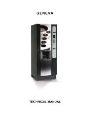
GENERAL DESCRIPTION<br />
8. The Neva 3 Beverage Machine is a free standing unit which may be mounted on a secure<br />
table, bench, cabinet or food and drink counter.<br />
Cabinet Front<br />
9. A swivel open door provides access to the three plastic ingredient canisters. The keypad<br />
and display are fitted to the front panel and are connected to the MPU Controller Board at<br />
the rear of the door.<br />
10. A gear driven worm screw located in the base of each canister dispenses ingredients in<br />
exact amounts. The ingredient is then mixed with hot water in a mixing bowl prior to the<br />
<strong>beverage</strong> being poured from the dispense head. A plastic agitator, located inside the<br />
canisters, ensures a free and consistent flow of powder. Additionally, a whipper unit,<br />
located beneath the mixing bowls, ensures that the product and water are properly blended.<br />
11. The <strong>machine</strong> On/Off switch is located on the lower panel. Access to all other components<br />
is either by removal of the motor shelf or side panels.<br />
Cabinet Interior<br />
12. Access to the internal parts of the <strong>machine</strong> is gained by removal of the ingredient canisters.<br />
Access to the boiler is then gained by removal of the boiler cover and lid assembly.<br />
Further access to the <strong>machine</strong> is achieved by removing the left-hand side panel, by lifting it<br />
upwards, clear of its keyhole slots. Removing this panel gives access to all internal<br />
components.<br />
13. The main water supply enters the <strong>machine</strong> via a gland at the rear of the cabinet and<br />
connects with the inlet valve. A length of tubing then takes the water supply into the top of<br />
the boiler. Hot water is directed from the boiler, via the appropriate solenoid operated<br />
valve, to the mixing bowl. A length of tubing directs any overflow from the boiler into the drip<br />
tray, and another length of tubing facilitates draining of the boiler.<br />
14. The mains electricity supply cable enters the <strong>machine</strong> via a cable gland at the rear of the<br />
<strong>machine</strong>, where it connects to a terminal block. The supply is then connected via a line<br />
filter to the On/Off switch on the front of the <strong>machine</strong>. The extract fan is located on the base<br />
of the <strong>machine</strong> and exhausts down towards the drip tray.<br />
NEVA 3 Issue 1 30/07/07 8