water heater series operator's manual - Shark Pressure Washers
water heater series operator's manual - Shark Pressure Washers
water heater series operator's manual - Shark Pressure Washers

You also want an ePaper? Increase the reach of your titles
YUMPU automatically turns print PDFs into web optimized ePapers that Google loves.
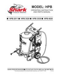
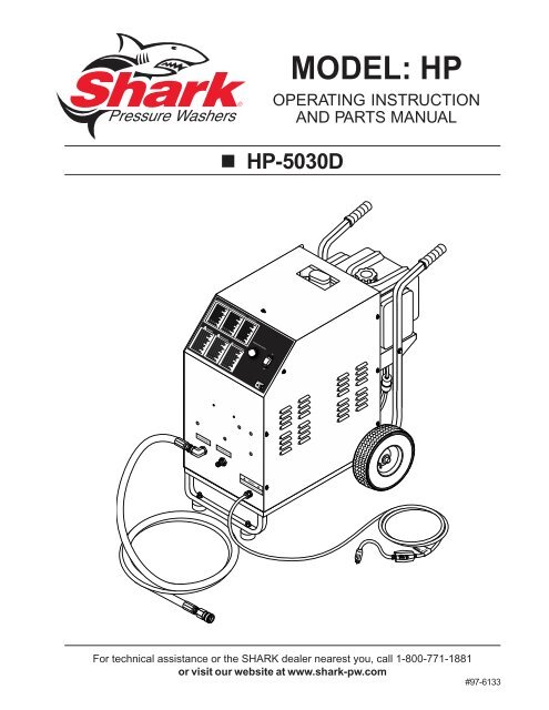
MODEL: HP<br />
OPERATING INSTRUCTION<br />
AND PARTS MANUAL<br />
■ HP-5030D<br />
For technical assistance or the SHARK dealer nearest you, call 1-800-771-1881<br />
or visit our website at www.shark-pw.com<br />
#97-6133
2<br />
MACHINE SPECIFICATIONS<br />
● Pump Volume At Pump Head:<br />
5 GPM<br />
● Pump <strong>Pressure</strong> At Pump Head:<br />
3000 PSI<br />
● Burner Type:<br />
Oil Fired - 380,000 BTU/Hr.<br />
● Burner Fuel <strong>Pressure</strong>:<br />
120 PSI<br />
● Machine Voltage:<br />
120V/1Ph<br />
● Total Machine Amperage:<br />
15 Amps<br />
● Shipping Weight:<br />
315 Lbs.<br />
● Exhaust Stack Size:<br />
3.5" x 6.5"<br />
● Machine Dimensions: Length = 29" Width = 41" Height = 47"<br />
Form #97-6133/#97-6149/#97-6162 • Revised 3/04
3<br />
CONTENTS<br />
Introduction ............................................................. 4<br />
Important Safety Information ................................4-5<br />
Installation ............................................................5,7<br />
Component Identification......................................... 6<br />
Starting and Operating Instructions ......................... 7<br />
Preventative Maintenance ....................................... 7<br />
Maintenance and Service ......................................8-9<br />
Field Service of Fuel Pump ..................................... 9<br />
Machine Assembly Exploded View.........................10<br />
Machine Assembly Exploded View Parts List ........11<br />
Burner Assembly, Exploded View ...........................12<br />
Burner Assembly Exploded View Parts Lists..........13<br />
Troubleshooting ................................................. 14-15<br />
Preventative Maintenance ......................................16<br />
Warranty<br />
SERIAL NUMBER:<br />
DATE PURCHASED:<br />
FOR SALES AND SERVICE, PLEASE CONTACT:<br />
Form #97-6133/#97-6149/#97-6162 • Revised 3/04
4 WATER HEATER SERIES OPERATOR’S MANUAL<br />
INTRODUCTION<br />
All information in this <strong>manual</strong> is based on the latest product<br />
information available at the time of printing.<br />
This machine is designed to heat <strong>water</strong> from a cold <strong>water</strong><br />
pressure washer. Maximum <strong>water</strong> flow is 5 GPM and maximum<br />
pressure is 3000 PSI. Flow rate of 3 GPM will<br />
achieve an average temperature of about 180°F. Temperature<br />
is dependent on inlet <strong>water</strong> temperature and <strong>water</strong><br />
flow rate.<br />
We reserve the right to make changes at any time without<br />
incurring any obligation.<br />
Owner/User Responsibility:<br />
The owner and/or user must have an understanding of<br />
the manufacturer’s operating instructions and warnings<br />
before using this hot <strong>water</strong> generator. Warning information<br />
should be emphasized and understood. If the operator<br />
is not fluent in English, the manufacturer’s instructions<br />
and warnings shall be read to and discussed with<br />
the operator in the operator’s native language by the purchaser/owner,<br />
making sure that the operator comprehends<br />
its contents.<br />
Owner and/or user must study and maintain for future<br />
reference the manufacturers’ instructions.<br />
This <strong>manual</strong> should be considered a permanent<br />
part of the machine and should remain with it<br />
if machine is resold.<br />
When ordering parts, please specify model and<br />
serial number.<br />
IMPORTANT SAFETY<br />
INFORMATION<br />
CAUTION: To reduce the risk of injury, read operating<br />
instructions carefully before using.<br />
1. Read the owner's <strong>manual</strong> thoroughly.<br />
Failure to follow instructions<br />
could cause malfunction<br />
CAUTION<br />
of the machine and result in<br />
death, serious bodily injury and/<br />
or property damage.<br />
READ OPERATOR’S<br />
MANUAL THOROUGHLY<br />
PRIOR TO USE.<br />
2. All installations must comply<br />
with local codes. Contact your<br />
electrician, plumber, utility company<br />
or the selling distributor for<br />
specific details.<br />
To comply with the National Electrical Code (NGPA<br />
70) and provide additional protection from risk of electric<br />
shock, this hot <strong>water</strong> generator is equipped with<br />
a UL approved ground fault circuit interrupter (GFCI)<br />
power cord.<br />
WARNING<br />
RISK OF FIRE.<br />
DO NOT USE WITH<br />
FLAMMABLE LIQUIDS.<br />
HIGH PRESSURE<br />
SPRAY CAN PIERCE<br />
SKIN AND TISSUES.<br />
WARNING: Flammable liquids can<br />
create fumes which can ignite<br />
causing property damage or<br />
severe injury.<br />
WARNING: Do not use gasoline,<br />
crankcase drainings or oil containing<br />
gasoline, solvents or alcohol.<br />
Doing so will result in fire and/<br />
or explosion.<br />
WARNING: Do not spray flammable liquids. Operate<br />
only where an open torch is permitted.<br />
3. This fuel burning machine shall be installed only in<br />
locations where combustible dusts and flammable<br />
gases or vapors are not present.<br />
4. In these oil burning models, use only kerosene,<br />
No. 1 home heating fuel, or diesel fuel.<br />
5. Risk of explosion — Do not spray flammable liquids.<br />
Operate only where open flame or torch is permitted.<br />
WARNING: Keep <strong>water</strong> spray, wand<br />
WARNING<br />
and high pressure hose away from<br />
electric wiring or fatal electric<br />
shock may result. Read warning<br />
tag on electrical cord.<br />
KEEP WATER SPRAY<br />
AWAY FROM<br />
ELECTRICAL WIRING.<br />
6. To protect the operator from<br />
electrical shock, the machine<br />
must be electrically grounded.<br />
It is the responsibility of the<br />
owner to connect this machine to a UL grounded<br />
receptacle of proper voltage and amperage ratings.<br />
Do not spray <strong>water</strong> on or near electrical components.<br />
Do not touch machine with wet hands or while<br />
standing in <strong>water</strong>. Always disconnect power before<br />
servicing.<br />
WARNING: Spray gun kicks back — hold with both<br />
hands.<br />
7. Grip cleaning wand of attached pressure washer securely<br />
with both hands before starting cleaner. Failure<br />
to do this could result in injury from a whipping wand.<br />
WARNING: High pressure stream<br />
WARNING<br />
of fluid that this equipment can<br />
produce can pierce the skin and<br />
its underlying tissues, leading<br />
to serious injury and possible<br />
amputation.<br />
8. High pressure developed by the<br />
attached pressure washer can<br />
cause bodily injury or damage.<br />
Use caution when operating. Do not point the spray<br />
gun at anyone or at any part of the body. This machine<br />
is to be used only by qualified operators.<br />
97-6149 • 97-6162 • 97-6133 • Rev. 3/04
WATER HEATER SERIES OPERATOR’S MANUAL 5<br />
9. Never make adjustments on machine while it is in<br />
operation.<br />
WARNING: High pressure spray<br />
WARNING<br />
can cause paint chips or other particles<br />
to become airborne and fly<br />
at high speeds.<br />
PROTECTIVE<br />
EYEWEAR AND<br />
CLOTHING MUST<br />
BE WORN.<br />
WARNING<br />
RISK OF<br />
ASPHYXIATION.<br />
USE ONLY IN A WELL<br />
VENTILATED AREA.<br />
WARNING<br />
RISK OF FIRE.<br />
DO NOT ADD FUEL<br />
WHEN OPERATING<br />
MACHINE.<br />
10. Eye safety devices must be<br />
worn when using this equipment.<br />
WARNING: Risk of asphyxiation —<br />
Use this product only in a well ventilated<br />
area.<br />
11. When the machine is working,<br />
do not cover or place in a<br />
closed space where ventilation<br />
is insufficient.<br />
WARNING: Risk of fire — Do not<br />
add fuel when the machine is<br />
operating or still hot.<br />
12. Attached pressure washer with<br />
a spray gun should not be operated<br />
with the spray gun in<br />
the OFF postion for extended<br />
periods of time as this may<br />
cause damage to the pump.<br />
Check to make sure burner shuts off when spray<br />
gun trigger is closed.<br />
13. Protect from freezing.<br />
14. To prevent a serious injury, make certain quick coupler<br />
on discharge hose has locked before using pressure<br />
washer.<br />
15. Do not allow acids, caustic or abrasive fluids to pass<br />
through the HP.<br />
16. Inlet <strong>water</strong> must be from a cold <strong>water</strong> pressure washer<br />
(3,000 PSI maximum).<br />
17. Do not allow CHILDREN to operate the pressure<br />
washer at any time. THIS MACHINE MUST BE AT-<br />
TENDED DURING OPERATION.<br />
18. The best insurance against an accident is precaution<br />
and knowledge of the machine.<br />
19. Do not operate this product when fatigued or under<br />
the influence of alcohol or drugs. Keep operating area<br />
clear of all persons.<br />
20. We will not be liable for any changes made to our<br />
standard machines, or any components not purchased<br />
from us.<br />
21. Do not overreach or stand on unstable support. Keep<br />
good footing and balance at all times.<br />
97-6149 • 97-6162 • 97-6133 • Rev. 3/04<br />
22. Follow the maintenance instructions specified in the<br />
<strong>manual</strong>.<br />
23. When making repairs disconnect from electrical<br />
source.<br />
24. Turn burner off and open spray gun to allow <strong>water</strong> to<br />
flow and cool coil to 100°F before turning machine off.<br />
25. Before disconnecting high pressure hose from<br />
HP <strong>water</strong> outlet, open spray gun to relieve back pressure<br />
in hose.<br />
CAUTION: This machine produces hot <strong>water</strong> and<br />
must have insulated components attached to protect<br />
the operator.<br />
INSTALLATION<br />
Place machine in a convenient location providing ample<br />
support, drainage and room for maintenance.<br />
Remove bolts from pallet to foot bracket. Install rubber<br />
feet provided as shown on page 11, item #26.<br />
Location:<br />
The location should protect the machine from damaging<br />
environmental conditions, such as; wind, rain, and<br />
freezing.<br />
1. This machine should be run on a level surface where<br />
it is not readily influenced by outside sources such as<br />
strong winds, freezing temperatures, rain, etc. It should<br />
be located to allow accessibility for refilling of fuel, adjustments<br />
and maintenance. Normal precautions<br />
should be taken by the operator of the machine to prevent<br />
moisture from reaching the electrical controls.<br />
2. It is recommended that a partition be made between<br />
the wash area and the machine to prevent <strong>water</strong><br />
spray from coming in contact with the machine. Excess<br />
moisture reaching any electric components or<br />
electrical controls will reduce machine life and may<br />
cause electrical shorts.<br />
3. During installation of the machine, beware of poorly<br />
ventilated locations or areas where exhaust fans may<br />
cause an insufficient supply of oxygen. Sufficient<br />
combustion can only be obtained when there is a<br />
sufficient supply of oxygen available for the amount<br />
of fuel being burned. If it is necessary to install a<br />
machine in a poorly ventilated area, outside fresh<br />
air may have to be piped to the burner and a fan<br />
installed to bring air into the machine.<br />
Electrical:<br />
This machine, when installed, must be electrically<br />
grounded in accordance to local codes. Check for proper<br />
power supply using a volt meter.
6 WATER HEATER SERIES OPERATOR’S MANUAL<br />
COMPONENT IDENTIFICATION<br />
CAUTION HOT WATER:<br />
Must use insulated<br />
spray gun and wand.<br />
<strong>Pressure</strong> Washer<br />
3,000 PSI Maximum<br />
(not included)<br />
Fresh Water<br />
Faucet<br />
<strong>Pressure</strong> Washer Coupler<br />
Garden Hose<br />
(not included)<br />
Diesel Fuel<br />
Tank<br />
Insulated Wand<br />
(not included)<br />
Insulated<br />
Spray Gun<br />
(not included)<br />
<strong>Pressure</strong> Washer<br />
to HP Inlet Hose<br />
Inlet<br />
Connection<br />
Outlet<br />
Connection<br />
Power Cord<br />
High <strong>Pressure</strong> Outlet Hose<br />
(not included)<br />
97-6149 • 97-6162 • 97-6133 • Rev. 3/04<br />
GFCI
WATER HEATER SERIES OPERATOR’S MANUAL 7<br />
Placement:<br />
Do not locate near any combustible material. Keep all<br />
flammable material at least 20 feet away.<br />
Allow enough space for servicing the machine.<br />
Local code will require certain distances from floor and<br />
walls. (Two feet away from walls should be adequate.)<br />
Water Source:<br />
The <strong>water</strong> source for the pressure washer should be supplied<br />
by a minimum 5/8" I.D. garden hose with a city <strong>water</strong><br />
pressure of not less than 30 PSI. If the <strong>water</strong> supply<br />
is inadequate, or if the garden hose is kinked, the attached<br />
pressure washer will run very rough and the<br />
burner will not fire.<br />
Connection:<br />
See Component Identification on page 6.<br />
Venting:<br />
Adding exhaust vent pipe to your oil fired burner is not<br />
recommended because restricted air flow causes carbon<br />
build-up, which affects the operation, and increases<br />
maintenance on the coil. If a stack must be used, refrain<br />
from using 90° bends. If the pipe can not go straight up<br />
then use only 45° bends and go to the next size pipe. The<br />
overall pipe length must not exceed 6 feet in length.<br />
STARTING AND OPERATING<br />
INSTRUCTIONS<br />
To Start:<br />
1. STOP! Read operator’s <strong>manual</strong> from both the pressure<br />
washer and the machine before operating. Failure<br />
to read operation and warning instructions may<br />
result in personal injury or property damage.<br />
2. Check fuel tank and pump oil levels on both<br />
machines.<br />
3. Connect garden hose to pressure washer.<br />
CAUTION: Only use fresh <strong>water</strong> to this machine.<br />
4. Attach high pressure hose between pressure washer<br />
and machine, as shown on page 6. Turn garden hose<br />
<strong>water</strong> on. Additional adapters and couplers may be<br />
needed to connect your brand of pressure washer to<br />
the machine.<br />
5. Connect the power cord into the proper electrical outlet,<br />
then push in the GFCI reset button.<br />
6. Start up attached pressure washer according to the<br />
manufacturers instructions. When a steady stream<br />
of <strong>water</strong> flows from the spray gun and wand the machine<br />
is ready for cold <strong>water</strong> cleaning.<br />
97-6149 • 97-6162 • 97-6133 • Rev. 3/04<br />
7. For hot <strong>water</strong> washing, turn the machine burner switch<br />
to the ON position. Adjust thermostat to desired temperature<br />
setting. (The burner will light automatically.)<br />
To Stop:<br />
1. If using an optional detergent injector, place the detergent<br />
line in a bucket of <strong>water</strong> allowing detergent<br />
to be flushed from system.<br />
2. Turn burner switch off and continue spraying <strong>water</strong>,<br />
allowing the <strong>water</strong> to cool.<br />
3. After <strong>water</strong> has cooled to less than 100°F, turn the<br />
attached pressure washer off.<br />
4. Turn garden hose <strong>water</strong> off. Open the spray gun to<br />
relieve remaining pressure.<br />
5. Protect from freezing.<br />
PREVENTATIVE MAINTENANCE<br />
1. Use clean fuel - kerosene, No. 1 home heating fuel or<br />
diesel. Clean or replace fuel filter every 100 hours of<br />
operation. Avoid <strong>water</strong> contaminated fuel as it will<br />
seize up the fuel pump. De-soot coils monthly. Use<br />
an additive if diesel is being used.<br />
2. Check to see that the attached pressure washer <strong>water</strong><br />
pump is properly lubricated.<br />
3. Follow winterizing instructions to prevent freeze damage<br />
to pump and coils.<br />
4. Always neutralize and flush detergent from system<br />
after use.<br />
5. If <strong>water</strong> is known to be high in mineral content, use a<br />
<strong>water</strong> softener on your <strong>water</strong> system, or de-scale as<br />
needed.<br />
6. Do not allow acidic, caustic or abrasive fluids to be<br />
pumped through system.<br />
7. Always use high grade quality cleaning products.<br />
8. Never run attached pressure washer pump dry for<br />
extended periods of time.<br />
9. If machine is operated with smoky or eye burning<br />
exhaust, coils will soot up, not letting <strong>water</strong> reach<br />
maximum operating temperature. (See section on<br />
Maintenance and Service).<br />
10. Never allow <strong>water</strong> to be sprayed on or near the motor<br />
or burner assembly or any electrical component.<br />
11. Delime coils as per instructions.<br />
It is advisable, periodically, to visually inspect the burner.<br />
Check air inlet to make sure it is not clogged or blocked.<br />
Wipe off any oil spills and keep equipment clean and dry.<br />
The areas around the HP should be kept clean and free<br />
of combustible materials, gasoline and other flammable<br />
vapors and liquids.<br />
The flow of ventilating air to the burner must not be blocked<br />
or obstructed in any manner.
8 WATER HEATER SERIES OPERATOR’S MANUAL<br />
MAINTENANCE AND SERVICE<br />
Winterizing Procedure:<br />
Damage due to freezing is not covered by warranty. Adhere<br />
to the following cold weather procedures whenever<br />
the washer must be stored or operated outdoors under<br />
freezing conditions.<br />
During winter months, when temperatures drop below<br />
32°F, protecting your machine against freezing is necessary.<br />
Store the machine in a heated room. If this is not<br />
possible use compressed air on the short hose end. By<br />
injecting compressed air, all <strong>water</strong> will be blown out of<br />
the system. Run anti-freeze through the system.<br />
Rupture Disk:<br />
For safety, each machine is equipped with a rupture disk.<br />
In the event the pressure of the <strong>water</strong> should exceed<br />
8000 PSI, the rupture disk will release pressure and <strong>water</strong><br />
on to the ground.<br />
When the disk ruptures, it will need to be replaced.<br />
NOTE: Turn burner switch off. Then open spray gun to<br />
cool heating coil or rupture disk will burst over time.<br />
Adjustable Thermostat:<br />
The adjustable thermostat can be set between 100°F to<br />
225°F (37.8° to 108°C). The temperature is dependent<br />
on <strong>water</strong> flow and ambient <strong>water</strong> temperature.<br />
Cleaning of Coils:<br />
In alkaline <strong>water</strong> areas, lime deposits can accumulate<br />
rapidly inside the coil pipes. This growth is increased by<br />
the extreme heat build up in the coil. The best prevention<br />
for liming conditions is to use high quality cleaning detergents.<br />
In areas where alkaline <strong>water</strong> is an extreme<br />
problem, periodic use of Deliming Powder will remove<br />
lime and other deposits before coil becomes plugged.<br />
Deliming Coils With A <strong>Pressure</strong> Washer:<br />
Periodic flushing of coils or optional float tank is recommended.<br />
Step 1 Fill a 5 gallon bucket with 4 gallons of <strong>water</strong>,<br />
then add 1 lb. of deliming powder. Mix thoroughly.<br />
Step 2 Remove the high pressure nozzle from the pressure<br />
wand and put the wand into the bucket.<br />
Secure the trigger on the spray gun in the open<br />
position.<br />
Step 3 Attach a short section (3-5 ft.) of garden hose to<br />
the attached pressure washer to siphon solution<br />
from the elevated bucket. Start up pressure<br />
washer, allowing solution to be pumped through<br />
pressure washer and into HP coils and back into<br />
the bucket. Solution should be allowed to circulate<br />
2-4 hours.<br />
97-6149 • 97-6162 • 97-6133 • Rev. 3/04<br />
Step 4 After circulating solution flush entire system with<br />
fresh <strong>water</strong>.<br />
Removal of Soot In Heating Coil:<br />
In the heating process fuel residue, in the form of soot<br />
deposits, may develop between the heating coil pipes<br />
and block air flow which affects burner combustion. When<br />
soot has been detected on visual observation, the soot<br />
on the coil must be cleaned off.<br />
Fuel:<br />
Use clean fuel oil that is not contaminated with <strong>water</strong> and<br />
debris. Replace fuel filter and drain tank every 100 hours<br />
of operation. Use Kerosene No. 1 or No. 2 Heating Fuel<br />
(ASTM D306) or diesel only. NEVER use gasoline in your<br />
burner tank. Gasoline is more combustible than fuel oil<br />
and could result in a serious explosion. NEVER use crankcase<br />
or waste oil in your burner. Fuel machine malfunction<br />
could result from contamination.<br />
Ignition Circuit:<br />
Periodically inspect wires, spring contact and electrodes<br />
for condition, security and proper spacing. (CAUTION:<br />
10,000 VOLTS)<br />
Electrode Setting:<br />
(See illustration below)<br />
Side View<br />
3/16"<br />
Gap<br />
1/8"<br />
Electrodes Check : Periodically check wiring connections.<br />
If necessary to adjust electrodes, use diagram.<br />
Burner Nozzle:<br />
Keep the tip free of surface deposits by wiping it with a<br />
clean, solvent-saturated cloth, being careful not to plug<br />
or enlarge the nozzle. For maximum efficiency, replace<br />
the nozzle each season. Select nozzle size based on<br />
the pressure washer you will be using:<br />
Nozzle <strong>Pressure</strong> Washer GPM<br />
1.50 2 - 3<br />
1.75 3 - 4<br />
2.00 - 2.25 4 - 5<br />
All nozzles should be 45° W
WATER HEATER SERIES OPERATOR’S MANUAL 9<br />
Fuel Control System:<br />
The machine utilizes a fuel solenoid valve located on the<br />
fuel pump to control the flow of fuel to the combustion<br />
chamber. This solenoid, which is normally closed, is activated<br />
by a flow switch when <strong>water</strong> is flowing through it.<br />
When an operator releases the trigger on the spray gun,<br />
the flow of <strong>water</strong> through the flow switch stops, turning<br />
off the current to the fuel solenoid. The solenoid then<br />
closes, shutting off the supply of fuel to the combustion<br />
chamber. Controlling the flow of fuel in this way gives an<br />
instantaneous burn or no burn situation, thereby eliminating<br />
high and low <strong>water</strong> temperatures, and combustion<br />
smoke normally associated with machines incorporating<br />
a spray gun. Periodic inspection is recommended to<br />
insure that the fuel solenoid valve functions properly. This<br />
can be done by operating the machine and checking to<br />
see that when the trigger on the spray gun is in the off<br />
position, the burner is not firing.<br />
Fuel <strong>Pressure</strong> Adjustment:<br />
To adjust fuel pressure, turn the adjusting screw with a<br />
5/32" Allen Wrench (located on the fuel pump) clockwise<br />
to increase, counterclockwise to decrease. Do not<br />
exceed 200 PSI.<br />
FIELD REPAIR INSTRUCTIONS<br />
HP Fuel Pump:<br />
1. Remove the screws 10/32" Allen Head from the machine<br />
hood.<br />
2. Remove louvered hood.<br />
3. With a 9/16" wrench, loosen (DO NOT REMOVE) the<br />
two 3/8" x 3/4" HH NC serrated flange bolts that secure<br />
the front panel.<br />
4. With a 2.5 mm hex head wrench (Allen Wrench),<br />
loosen the three set screws that hold the fuel pump<br />
in the blower motor housing located on Idromatic<br />
Boiler Assembly.<br />
5. Carefully remove the fuel pump (Item #53) from the<br />
blower motor, leaving the flexible zinc fuel line connected,<br />
carefully bend the fuel line and fuel pump<br />
away from the blower motor.<br />
6. Locate the fuel pump/fan motor coupling.<br />
7. Inspect the coupling for damage. The inside diameter<br />
of fuel pump coupling requires flat on one side<br />
to engage fuel pump, and the outside diameter requires<br />
two male notches to engage the blower motor.<br />
8. Perform a check to see if the fuel pump is turning<br />
freely. Use an open end 7mm wrench or small adjustable<br />
wrench on fuel pump shaft.<br />
9. Spin the fuel pump over in both directions using the<br />
wrench for leverage. When the fuel pump is turning<br />
freely (almost to the point you could turn it by hand)<br />
it is ready to reinstall.<br />
10. Align fuel pump coupler on pump shaft/fan motor.<br />
Slide pump into fan motor. Secure pump with the three<br />
set screws.<br />
11. Test machine (make sure):<br />
❑ Blower motor spins<br />
❑ Fuel is on<br />
❑ Machine has power to it<br />
❑ Switch is on<br />
❑ Flow of <strong>water</strong> through machine<br />
❑ Thermostat is turned up<br />
❑ Flow switch is adjusted properly<br />
12. When HP is operating properly, turn machine off,<br />
tighten front panel, and install hood and 13 self tapping<br />
screws with recess washers.<br />
97-6149 • 97-6162 • 97-6133 • Rev. 3/04
10 WATER HEATER SERIES OPERATOR’S MANUAL<br />
MACHINE ASSEMBLY<br />
EXPLODED VIEW<br />
31<br />
25<br />
12<br />
33<br />
14<br />
1<br />
35<br />
16<br />
29<br />
11<br />
10<br />
28<br />
21<br />
4<br />
13<br />
6<br />
36 - Reverse<br />
View<br />
38<br />
37<br />
39<br />
2<br />
40<br />
22<br />
17<br />
8<br />
9<br />
20<br />
24<br />
27<br />
3<br />
30<br />
23<br />
29<br />
15<br />
28<br />
18<br />
34<br />
97-6149 • 97-6162 • 97-6133 • Rev. 3/04<br />
19<br />
7<br />
5<br />
32
WATER HEATER SERIES OPERATOR’S MANUAL 11<br />
MACHINE ASSEMBLY<br />
EXPLODED VIEW PARTS LIST<br />
ITEM PART NO. DESCRIPTION QTY<br />
1 2-01167 Cap, Fuel Tank, Plastic 1<br />
2 2-99031 Filter, Diesel Fuel, Disposable 1<br />
3 4-0303 Wheel & Tire, 6" Steel Rim 2<br />
4 4-05088 Thermostat, Adjustable, 302°F 1<br />
5 6-01062 GFCI, 120V 15A, w/36' 12-3 Cord 1<br />
6 6-020240 Switch, Rocker,<br />
Carling w/Green Lens 1<br />
7 6-05152 Strain Relief, Strt,<br />
LQ Tite 3231 Small 1<br />
8 90-1987 Screw, 6/32" x 2" 2<br />
9 90-20041 Collar, 5/8" Bore Shaft 3010 2<br />
95-07102225 ▲ Axle 1<br />
90-4005 ▲ Washer, 5/8" 4<br />
10 95-07200122 Bracket, Fuel Tank, Left 1<br />
95-07200124 Bracket, Fuel Tank, Right 1<br />
11 95-07200125 Frame Assy 1<br />
90-1996 ▲ Bolt, 3/8" x 3/4" Whiz 4<br />
90-2020 ▲ Nut Cage, 3/8" x 12 GA 4<br />
90-2022 ▲ Nut Cage, 1/4" x 16 GA 4<br />
12 95-07200123 Hood, Cover Panel 1<br />
95-07290056 Hood, Eurotec Coil 1<br />
11-0101 ▲ Label, Warning, Pictorial 1<br />
10-02025A ▲ Label, Hot/Caliente<br />
w/Arrows 1<br />
13 95-07200121 Panel, Front 1<br />
11-1042 ▲ Label, Ground 1<br />
14 95-07102287 Strap, Fuel Tank 2<br />
15 2-01015 Bumber, Rubber 1" w/Bolt,<br />
5/16" x 1-1/4" 2<br />
16 2-011507 Tank, Encore 5 Gal Fuel 1<br />
2-1084 ▲ Hose Barb,<br />
1/4" Barb x 1/8" Pipe 1<br />
2-010061 ▲ Grommet, Fuel Tank 1<br />
7-80320 ▲ Valve, Fuel Tank Shut-Off 1<br />
ITEM PART NO. DESCRIPTION QTY<br />
17 95-07200120 Panel, Back 1<br />
90-1996 ▲ Bolt, 3/8" x 3/4" Whiz 4<br />
90-2020 ▲ Nut Cage, 3/8" x 12 GA 4<br />
18 2-2007 Nipple, 3/8" x 3/8" NPT ST Male1<br />
19 2-2002 Coupler, 3/8" Fem, Brass 1<br />
20 2-0031 Elbow, 3/8" Street 1<br />
21 11-0110 Label, Control Panel 1<br />
22 4-02100003 Fuel Line, 1/4" Push-On, Green<br />
(36") 1<br />
23 10-09004 Decal, Discharge 1<br />
24 10-09003 Decal, Inlet 1<br />
25 11-013 Label, <strong>Shark</strong> Logo 2<br />
26 90-20061 ▲ Nut, 5/16", Cap 2<br />
27 90-1018 Bolt, 5/16" x 1-3/4" 4<br />
90-4002 Washer, 3/4", Flat 4<br />
90-2002 Nut, Whiz Loc, 5/16" Flange 4<br />
28 90-1004 Bolt, 1/4" x 1-1/2" 2<br />
90-4000 Washer, 1/4", Flat 2<br />
90-200012 Nut, 1/4" Flange 2<br />
29 90-2018 Nut, Cage, 10/32" x 16 Ga. 15<br />
30 4-0204509 Hose, 3/8" x 9', 2 Wire,<br />
3/8" SW, x 3/8" SOL 1<br />
31 90-1991 Screw, 10/32" x 1/2" 15<br />
32 10-08018 Label, Warning, Service Cord 1<br />
33 2-01103 Grip, 1" Sqr. Handle 2<br />
34 10-08021 Label, Disconnect Pwr Supply 1<br />
35 7-726679 Ignition Wire/Silicon Cable 2<br />
36 6-05040 Block, Terminal, 8 Pole 1<br />
37 7-40050 Transformer, 115V 1<br />
38 90-200430 Nut, 6/32", Keps 2<br />
39 4-02100003 Fuel Line, 1/4" Push-On, Green<br />
(6") 1<br />
40 4-02100000 Fuel Line, 1/4", Black (46") 1<br />
▲ Not Shown<br />
97-6149 • 97-6162 • 97-6133 • Rev. 3/04
12 WATER HEATER SERIES OPERATOR’S MANUAL<br />
BURNER ASSEMBLY<br />
EXPLODED VIEW PARTS LIST<br />
30<br />
29<br />
31<br />
12<br />
18<br />
14<br />
28<br />
22<br />
To Fuel<br />
Tank<br />
4<br />
15<br />
5,7<br />
26<br />
23<br />
21<br />
Inlet<br />
20<br />
10<br />
19<br />
21<br />
8<br />
3<br />
16<br />
27<br />
9<br />
6<br />
2<br />
25<br />
Outlet<br />
1<br />
13<br />
24<br />
11<br />
97-6149 • 97-6162 • 97-6133 • Rev. 3/04
WATER HEATER SERIES OPERATOR’S MANUAL 13<br />
BURNER ASSEMBLY<br />
EXPLODED VIEW PARTS LIST<br />
ITEM PART NO. DESCRIPTION QTY<br />
1 2-0036 Tee, 1/2", Fem., Steel Pipe 1<br />
2 2-0046 Tee, 1/2", Street 1<br />
3 2-0052 Nipple, 1/2" JIC x 1/2" Pipe 1<br />
2-0054 ▲ Elbow, 1/2" JIC x 1/2" Male 1<br />
4 2-0103 Grommet, Rubber,<br />
Nozzle Holder 2<br />
5 2-1084 Hose Barb,<br />
1/4" Barb x 1/8" ML Pipe 2<br />
6 2-3409 Disk, Rupture Assy, 7000 PSI 1<br />
7 2-9040 Clamp, Hose, UNI, .46-.54 6<br />
8 4-02047716 Hose, 3/8" x 16", 2 Wire,<br />
<strong>Pressure</strong> Loop 1<br />
9 2-00681 Bushing, 1/2" x 3/8" 1<br />
10 6-021730 Switch, Flow, MV60 1<br />
11 95-07102288 Guard, Boiler/Plumbing 1<br />
12 91-010170 Coil, Lavorwash 1<br />
13 4-02047722 Hose, 3/8" x 22", 2 Wire,<br />
<strong>Pressure</strong> Loop 1<br />
14 7-40112 ▲ Solenoid, w/Valve,<br />
115V 60 HZ 1<br />
15 2-0053 Elbow, 1/2" JIC x 3/8", 90° 1<br />
16 2-00602 Elbow, 1/2" JIC x 1/2" Fem, 90° 1<br />
2-00601 Elbow, 1/2" JIC x 3/8" Male<br />
(5530, 4030) 1<br />
17 7-00216 Fuel Pump 1<br />
ITEM PART NO. DESCRIPTION QTY<br />
17 7-50044 ▲ Coupling, Fuel Pump 1<br />
18 7-15070 Coil Replacement 1<br />
19 6-021740 Reed, Replacement, MV60 1<br />
20 2-0006 Nipple, 3/8" x 3/8" Hex, Steel 1<br />
21 2-11039 Connector, 3/8" Anchor 2<br />
22 90-19711 Screw, 1/4" x 1/2", Whiz Loc 4<br />
23 2-1019 Elbow, 3/8" Female 1<br />
24 4-05088 Thermostat, Adjustable, 302°F 1<br />
25 2-0051 Nipple, 1/2" JIC x 3/8" Pipe 1<br />
2-0053 Elbow (3535, 4030) 1<br />
26 Coil, Mount Plate 1<br />
90-1006 ▲ Bolt, 5/16" x 3/4" 4<br />
90-4001 ▲ Washer, 5/16" 8<br />
90-2001 ▲ Nut, 5/16" ESNA 4<br />
27 7-00220 Motor, Burner, 115V 60 HZ 1<br />
7-50034 ▲ Blower Wheel 1<br />
28 7-25086 Fuel Line 1<br />
29 7-55041 Electrodes 2<br />
30 7-25079 Holder, Fuel Nozzle 1<br />
31 7-55029 Site Glass 1<br />
▲ Not Shown<br />
97-6149 • 97-6162 • 97-6133 • Rev. 3/04
14 WATER HEATER SERIES OPERATOR’S MANUAL<br />
TROUBLESHOOTING<br />
PROBLEM POSSIBLE CAUSE SOLUTION<br />
BURNER WILL NOT<br />
LIGHT<br />
Disconnected or short in electrical<br />
wiring<br />
Burner motor thermal protector<br />
tripped<br />
ON/OFF switch defective<br />
Heavy sooting on coil and burner,<br />
can cause interruption of air flow and<br />
shorting of electrodes<br />
Improper electrode setting<br />
Fuel not reaching combustion<br />
chamber<br />
Fuel solenoid malfunction<br />
Clogged burner nozzle<br />
Water not turned on<br />
Flow switch malfunction<br />
All wire contacts should be clean and tight. No<br />
breaks in wire.<br />
If tripped, check voltage, connections and<br />
extensions for cause. Check fuel pump shaft<br />
rotation for binding, causing motor to overheat.<br />
Check continuity through burner switch.<br />
Clean as required.<br />
Clean and test according to diagram in<br />
<strong>operator's</strong> <strong>manual</strong>.<br />
Check fuel pump for proper flow. Check<br />
solenoid flow switch on machines with spray<br />
gun control for proper ON/OFF flow switch.<br />
Check by placing screwdriver inside coil then<br />
turn machine on, open spray gun and check for<br />
magnetic pull.<br />
Replace.<br />
Turn on <strong>water</strong> to activate burner flow switch.<br />
Remove, test for continuity and replace as<br />
needed.<br />
MACHINE SMOKES Improper fuel or <strong>water</strong> in fuel Drain tank and replace contaminated fuel.<br />
Low fuel pressure<br />
Air leaks in fuel lines<br />
Plugged or dirty burner nozzle<br />
Faulty burner nozzle spray pattern<br />
Heavy accumulation of soot on coils<br />
and burner assembly<br />
Misaligned electrode<br />
Fuel filter partially clogged<br />
Obstruction in smoke stack<br />
Soot build-up on coils<br />
Lime build-up in coils<br />
Adjust fuel pump pressure to specifications.<br />
Check fuel lines for leaks or air bubbles.<br />
Tighten or replace as needed.<br />
Replace.<br />
Replace nozzle.<br />
Remove coils and burner assembly. Clean<br />
thoroughly.<br />
Realign electrodes to specifications.<br />
Replace as needed.<br />
Check for insulation blockage or other foreign<br />
objects.<br />
Clean coils with soot remover.<br />
Clean inside of coils using coil cleaner.<br />
97-6149 • 97-6162 • 97-6133 • Rev. 3/04
WATER HEATER SERIES OPERATOR’S MANUAL 15<br />
TROUBLESHOOTING<br />
PROBLEM POSSIBLE CAUSE SOLUTION<br />
LOW WATER<br />
TEMPERATURE<br />
WATER<br />
TEMPERATURE<br />
TOO HOT<br />
Improper fuel or <strong>water</strong> in fuel<br />
Low fuel pressure<br />
Weak fuel pump<br />
Fuel filter partially clogged<br />
Soot build up on coils<br />
Lime build up on coils<br />
Improper burner nozzle<br />
Incoming <strong>water</strong> to machine warm or<br />
hot<br />
Fuel pump pressure too high<br />
Fuel pump defective<br />
Detergent line sucking air<br />
Defective high limit switch (thermostat)<br />
Incorrect fuel nozzle size<br />
Insufficient <strong>water</strong> supplied<br />
Restricted <strong>water</strong> flow<br />
Drain fuel tank and replace with proper fuel.<br />
Increase fuel pressure.<br />
Check fuel pump temperature. Replace pump<br />
if needed.<br />
Replace as needed.<br />
Clean coils with soot remover.<br />
Clean inside of coils using <strong>Shark</strong>'s coil<br />
cleaner.<br />
See specifications.<br />
Lower incoming <strong>water</strong> temperature.<br />
Lower fuel pressure.<br />
Replace fuel pump.<br />
Tighten all clamps. Check detergent line for<br />
holes.<br />
Replace.<br />
See Burner Nozzle section.<br />
Check GPM to machine.<br />
Check nozzle for obstruction, proper size.<br />
97-6149 • 97-6162 • 97-6133 • Rev. 3/04
16 WATER HEATER SERIES OPERATOR’S MANUAL<br />
PREVENTATIVE MAINTENANCE<br />
MAINTENANCE SCHEDULE<br />
Machine Clean Daily<br />
Water Lines Check Daily<br />
Fittings Check Daily<br />
Fuel Filter Clean Weekly<br />
Inlet Strainer Clean Weekly<br />
Fuel Nozzle Clean Weekly<br />
Fuel Tank Clean Weekly<br />
Electrodes Adjust Monthly<br />
Fuel Pump Strainer Clean Monthly<br />
Electrode Wires Check Monthly<br />
97-6149 • 97-6162 • 97-6133 • Rev. 3/04
HP SERIES HEATER MODULE<br />
WARRANTY<br />
SHARK LIMITED NEW PRODUCT WARRANTY<br />
PRESSURE WASHERS<br />
WHAT THIS WARRANTY COVERS<br />
All SHARK PRESSURE WASHERS are warranted by SHARK to the original purchaser to be free from defects in materials and<br />
workmanship under normal use, for the periods specified below. This Limited Warranty is subject to the exclusions shown below,<br />
is calculated from the date of the original purchase, and applies to the original components only. Any parts replaced under this<br />
warranty will assume the remainder of the part’s warranty period. This warranty applies to the original purchaser and is not<br />
transferable.<br />
LIMITED LIFETIME PARTS WARRANTY:<br />
Components manufactured by SHARK, such as frames, handles, coil wraps, float tanks, and belt guards. Forged brass pump<br />
manifold. All heating coils will have a three year warranty. Internal components on the oil-end of all pressure washer pumps will<br />
have a seven year warranty.<br />
ONE YEAR PARTS WARRANTY:<br />
All other components, excluding normal wear items as described below, will be warranted for one year on parts. Warranty on<br />
these parts will be for one year regardless of the duration of the original component manufacturer’s part warranty.<br />
WARRANTY PROVIDED BY OTHER MANUFACTURERS:<br />
Motors, generators, and engines, which are warranted by their respective manufacturers, are serviced through these manufacturers’<br />
local authorized service centers. SHARK cannot provide warranty on these items.<br />
WHAT THIS WARRANTY DOES NOT COVER<br />
This warranty does not cover the following items:<br />
1. Normal wear items, such as nozzles, guns, discharge hoses, wands, quick couplers, seals, filters, gaskets, O-rings,<br />
packings, pistons, pump valve assemblies, strainers, belts, brushes, rupture disks, fuses, pump protectors.<br />
2. Damage or malfunctions resulting from accidents, abuse, modifications, alterations, incorrect installation, improper<br />
servicing, failure to follow manufacturer’s maintenance instructions, or use of the equipment beyond its stated usage<br />
specifications as contained in the operator’s <strong>manual</strong>.<br />
3. Damage due to freezing, chemical deterioration, scale buildup, rust, corrosion, or thermal expansion.<br />
4. Damage to components from fluctuations in electrical or <strong>water</strong> supply.<br />
5. Normal maintenance service, including adjustments, fuel system cleaning, and clearing of obstructions.<br />
6. Transportation to service center, shop labor charges, field labor charges, or freight damage.<br />
WHAT YOU MUST DO TO OBTAIN WARRANTY SERVICE<br />
While not required for warranty service, we request that you register your SHARK pressure washer by returning the completed<br />
registration card. In order to obtain warranty service on items, you must return the product to an Authorized SHARK Dealer,<br />
freight prepaid, with proof of purchase, within the applicable warranty period. If the product is permanently installed, you must<br />
notify your Authorized SHARK Dealer of the defect. The Authorized Dealer will file a claim, which must subsequently verify the<br />
defect. In most cases, the part must be returned to SHARK freight prepaid with the claim. For warranty service on components<br />
warranted by other manufacturers, the Authorized Dealer can help you obtain warranty service through these manufacturers’<br />
local authorized service centers.<br />
LIMITATION OF LIABILITY<br />
SHARK’S liability for special, incidental, or consequential damages is expressly disclaimed. In no event shall SHARK’S liability<br />
exceed the purchase price of the product in question. SHARK makes every effort to ensure that all illustrations and specifications<br />
are correct, however, these do not imply a warranty that the product is merchantable or fit for a particular purpose, or that<br />
the product will actually conform to the illustrations and specifications. THE WARRANTY CONTAINED HEREIN IS IN LIEU OF<br />
ALL OTHER WARRANTIES, EXPRESS OR IMPLIED, INCLUDING ANY IMPLIED WARRANTY OF FITNESS FOR A PAR-<br />
TICULAR PURPOSE. SHARK does not authorize any other party, including authorized Dealers, to make any representation or<br />
promise on behalf of SHARK, or to modify the terms, conditions, or limitations in any way. It is the buyer’s responsibility to ensure<br />
that the installation and use of SHARK products conforms to local codes. While SHARK attempts to assure that its products<br />
meet national codes, it cannot be responsible for how the customer chooses to use or install the product.<br />
SHARK PRESSURE WASHERS<br />
1-360-833-9100 • 1-800-771-1881 • www.shark-pw.com<br />
<strong>Shark</strong> HP • 97-6133 • Rev. 3/04
Form #97-6133 • Revised 3/04 • Printed in U.S.A.