intensity-modulated radiotherapy: current status and issues
intensity-modulated radiotherapy: current status and issues
intensity-modulated radiotherapy: current status and issues

You also want an ePaper? Increase the reach of your titles
YUMPU automatically turns print PDFs into web optimized ePapers that Google loves.
PII S0360-3016(01)01749-7<br />
Int. J. Radiation Oncology Biol. Phys., Vol. 51, No. 4, pp. 880–914, 2001<br />
Copyright © 2001 Elsevier Science Inc.<br />
Printed in the USA. All rights reserved<br />
0360-3016/01/$–see front matter<br />
CRITICAL REVIEW<br />
INTENSITY-MODULATED RADIOTHERAPY:<br />
CURRENT STATUS AND ISSUES OF INTEREST<br />
Intensity Modulated Radiation Therapy Collaborative Working Group<br />
TABLE OF CONTENTS<br />
ABSTRACT<br />
INTRODUCTION<br />
IMRT HISTORICAL REVIEW<br />
3D treatment planning systems<br />
Precursors to IMRT delivery systems<br />
IMRT DELIVERY TECHNIQUES<br />
Scanned photon <strong>and</strong> electron beam IMRT<br />
Tomotherapy IMRT<br />
Conventional multileaf collimator IMRT<br />
Physical modulator (compensating filter) IMRT<br />
Robotic linear accelerator IMRT<br />
COMPUTER OPTIMIZATION<br />
Objective functions<br />
Computer optimization (search) process<br />
Leaf sequence generation<br />
DOSE DISTRIBUTION AND MONITOR UNIT<br />
CALCULATIONS FOR IMRT<br />
Calculation algorithm types<br />
Important <strong>issues</strong> for IMRT dose calculations<br />
Monitor unit calculations for IMRT<br />
Recommendations: IMRT dose calculations<br />
IMRT ACCEPTANCE TESTING, COMMISSIONING,<br />
AND QA<br />
Acceptance testing of the IMRT treatment planning system<br />
Verification of IMRT dose distributions<br />
IMRT treatment plan test cases<br />
QA checks of monitor unit calculations<br />
IMRT treatment verification<br />
Recommendations: Acceptance testing, commissioning, <strong>and</strong><br />
QA of IMRT systems <strong>and</strong> treatment verification<br />
FACILITY PLANNING AND RADIATION SAFETY<br />
Workload estimates<br />
Dose rate <strong>and</strong> calibration changes<br />
Shielding design<br />
Patient whole-body dose<br />
Recommendations: Facility planning <strong>and</strong> radiation safety<br />
TARGET VOLUME AND DOSE SPECIFICATION<br />
AND REPORTING<br />
Target volume specification<br />
Dose specification<br />
Recommendations: Target volume <strong>and</strong> dose specification<br />
CLINICAL EXPERIENCE<br />
SUMMARY AND CONCLUSIONS<br />
ACKNOWLEDGMENTS<br />
APPENDIX A: IMRT NOMENCLATURE<br />
REFERENCES<br />
Intensity Modulated Radiation Therapy Collaborative Working<br />
Group: Arthur L. Boyer, Ph.D., E. Brian Butler, M.D., Thomas A.<br />
DiPetrillo, M.D., Mark J. Engler, Ph.D., Benedick Fraass, Ph.D.,<br />
Walter Grant, III, Ph.D., C. Clifton Ling, Ph.D., Daniel A. Low,<br />
Ph.D., Thomas R. Mackie, Ph.D., Radhe Mohan, Ph.D., James A.<br />
Purdy, Ph.D. (Chairman), Mack Roach, M.D., Julian G. Rosenman,<br />
M.D., Ph.D., Lynn J. Verhey, Ph.D., <strong>and</strong> John W. Wong,<br />
Ph.D. National Cancer Institute: Richard L. Cumberlin, M.D.,<br />
Helen Stone, Ph.D American Association of Physicists in Medicine<br />
Liaison: Jatinder R. Palta, Ph.D.<br />
880
IMRT: <strong>current</strong> <strong>status</strong> <strong>and</strong> <strong>issues</strong> of interest ● IMRT CWG<br />
881<br />
Purpose. To develop <strong>and</strong> disseminate a report aimed primarily at practicing radiation oncology physicians <strong>and</strong><br />
medical physicists that describes the <strong>current</strong> state-of-the-art of <strong>intensity</strong>-<strong>modulated</strong> <strong>radiotherapy</strong> (IMRT). Those<br />
areas needing further research <strong>and</strong> development are identified by category <strong>and</strong> recommendations are given,<br />
which should also be of interest to IMRT equipment manufacturers <strong>and</strong> research funding agencies.<br />
Methods <strong>and</strong> Materials. The National Cancer Institute formed a Collaborative Working Group of experts in<br />
IMRT to develop consensus guidelines <strong>and</strong> recommendations for implementation of IMRT <strong>and</strong> for further<br />
research through a critical analysis of the published data supplemented by clinical experience. A glossary of the<br />
words <strong>and</strong> phrases <strong>current</strong>ly used in IMRT is given in the Appendix. Recommendations for new terminology are<br />
given where clarification is needed.<br />
Results. IMRT, an advanced form of external beam irradiation, is a type of three-dimensional conformal<br />
<strong>radiotherapy</strong> (3D-CRT). It represents one of the most important technical advances in RT since the advent of the<br />
medical linear accelerator. 3D-CRT/IMRT is not just an add-on to the <strong>current</strong> radiation oncology process; it<br />
represents a radical change in practice, particularly for the radiation oncologist. For example, 3D-CRT/IMRT<br />
requires the use of 3D treatment planning capabilities, such as defining target volumes <strong>and</strong> organs at risk in three<br />
dimensions by drawing contours on cross-sectional images (i.e., CT, MRI) on a slice-by-slice basis as opposed to<br />
drawing beam portals on a simulator radiograph. In addition, IMRT requires that the physician clearly <strong>and</strong><br />
quantitatively define the treatment objectives. Currently, most IMRT approaches will increase the time <strong>and</strong><br />
effort required by physicians, medical physicists, dosimetrists, <strong>and</strong> radiation therapists, because IMRT planning<br />
<strong>and</strong> delivery systems are not yet robust enough to provide totally automated solutions for all disease sites.<br />
Considerable research is needed to model the clinical outcomes to allow truly automated solutions. Current<br />
IMRT delivery systems are essentially first-generation systems, <strong>and</strong> no single method st<strong>and</strong>s out as the ultimate<br />
technique. The instrumentation <strong>and</strong> methods used for IMRT quality assurance procedures <strong>and</strong> testing are not<br />
yet well established. In addition, many fundamental questions regarding IMRT are still unanswered. For<br />
example, the radiobiologic consequences of altered time–dose fractionation are not completely understood. Also,<br />
because there may be a much greater ability to trade off dose heterogeneity in the target vs. avoidance of normal<br />
critical structures with IMRT compared with traditional RT techniques, conventional radiation oncology<br />
planning principles are challenged. All in all, this new process of planning <strong>and</strong> treatment delivery has significant<br />
potential for improving the therapeutic ratio <strong>and</strong> reducing toxicity. Also, although inefficient <strong>current</strong>ly, it is<br />
expected that IMRT, when fully developed, will improve the overall efficiency with which external beam RT can<br />
be planned <strong>and</strong> delivered, <strong>and</strong> thus will potentially lower costs.<br />
Conclusion. Recommendations in the areas pertinent to IMRT, including dose–calculation algorithms, acceptance<br />
testing, commissioning <strong>and</strong> quality assurance, facility planning <strong>and</strong> radiation safety, <strong>and</strong> target volume <strong>and</strong><br />
dose specification, are presented. Several of the areas in which future research <strong>and</strong> development are needed are<br />
also indicated. These broad recommendations are intended to be both technical <strong>and</strong> advisory in nature, but the<br />
ultimate responsibility for clinical decisions pertaining to the implementation <strong>and</strong> use of IMRT rests with the<br />
radiation oncologist <strong>and</strong> radiation oncology physicist. This is an evolving field, <strong>and</strong> modifications of these<br />
recommendations are expected as new technology <strong>and</strong> data become available. © 2001 Elsevier Science Inc.<br />
IMRT, 3D treatment planning, Inverse planning, Optimization, Dose calculations, 3D conformal therapy, Quality<br />
assurance.<br />
INTRODUCTION<br />
Radiotherapy (RT) planning <strong>and</strong> delivery are in the process<br />
of changing dramatically. This change is being<br />
driven in large part by continuing advances in computer<br />
hardware <strong>and</strong> software that has led to the development of<br />
sophisticated three-dimensional radiation treatment planning<br />
(3D-RTP) <strong>and</strong> computer-controlled radiation therapy<br />
(CCRT) delivery systems (1–3). Such planning <strong>and</strong><br />
delivery systems have made practical the implementation<br />
of three-dimensional conformal radiation therapy (3D-<br />
CRT). The goal of 3D-CRT is to conform the spatial<br />
distribution of the prescribed dose to the 3D target volume<br />
(cancerous cells plus a margin for spatial uncertainties)<br />
<strong>and</strong> at the same time minimize the dose to the<br />
surrounding normal structures. Typically, the delivery of<br />
Reprint requests to: James A. Purdy, Ph.D., Radiation Oncology<br />
Center, Mallinckrodt Institute of Radiology, 510 South Kingshighway<br />
Blvd., St. Louis, MO 63110.<br />
Acknowledgments— The IMRT CWG thanks the members of the<br />
Radiation Therapy Committee of the American Association of<br />
Physicists in Medicine chaired by Jatinder Palta <strong>and</strong> the members<br />
3D-CRT is accomplished with a set of fixed radiation<br />
beams, which are shaped using the projection of the<br />
target volume. The radiation beams normally have a<br />
uniform <strong>intensity</strong> across the field, or, where appropriate,<br />
have this <strong>intensity</strong> modified by simple beam fluencemodifying<br />
devices, such as wedges or compensating filters.<br />
However, even before this form of 3D-CRT (henceforth<br />
referred to as conventional 3D-CRT) has been implemented<br />
throughout the radiation oncology community, a new type<br />
of conformal planning <strong>and</strong> delivery technology is evolving.<br />
This new type of 3D-CRT, <strong>intensity</strong>-<strong>modulated</strong> radiation<br />
therapy (IMRT), is based on the use of optimized nonuniform<br />
radiation beam intensities incident on the patient<br />
(Fig. 1) (4, 5). IMRT treatment plans are often generated<br />
using inverse planning or automated optimization 3D-RTP<br />
of the Medical Physics Committee of the American Society for<br />
Therapeutic Radiology <strong>and</strong> Oncology chaired by R<strong>and</strong>all Ten<br />
Haken for their review <strong>and</strong> helpful suggestions.<br />
Received Oct 24, 2000, <strong>and</strong> in revised form Jul 3, 2001. Accepted<br />
for publication Jul 6, 2001.
882 I. J. Radiation Oncology ● Biology ● Physics Volume 51, Number 4, 2001<br />
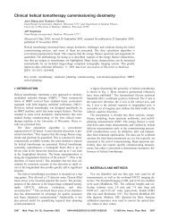
Fig. 1. Advanced form of 3D-CRT—IMRT—which is based on the use of optimized non-uniform radiation beam<br />
intensities incident on the patient. Shown is a 3D view of the patient, the PTV, spinal cord, <strong>and</strong> parotid gl<strong>and</strong>s, <strong>and</strong> the<br />
9 <strong>intensity</strong> <strong>modulated</strong> beams (with gray levels reflecting the <strong>intensity</strong> value) used to generate the IMRT dose<br />
distribution.<br />
systems, which use computer optimization techniques to<br />
help determine the distribution of intensities across the<br />
target volume.<br />
In any new area of technology, new words <strong>and</strong> new uses<br />
of old words rapidly come into being. Although this is<br />
necessary <strong>and</strong> desirable, a poorly defined term can lead to a<br />
misunderst<strong>and</strong>ing in reporting the clinical results <strong>and</strong> also in<br />
research <strong>and</strong> development. For example, various other descriptors<br />
have been used in the past in reference to IMRT,<br />
including generalized 3D-CRT, unconstrained 3D-CRT,<br />
<strong>and</strong> computer-controlled conformal RT (2, 4, 6–9). The<br />
IMRT Collaborative Working Group (CWG) supports the<br />
establishment of a consistent <strong>and</strong> clear nomenclature for use<br />
in IMRT. To this end, a glossary of words <strong>and</strong> phrases<br />
<strong>current</strong>ly used in IMRT is given in the Appendix. Where<br />
clarification is needed, recommendations for new terminology<br />
are given.<br />
As emphasized throughout this report, IMRT techniques<br />
are significantly more complex than many other traditional<br />
forms of RT, including conventional 3D-CRT. However, as<br />
discussed in later sections of this report, IMRT has the<br />
potential to achieve a much higher degree of target conformity<br />
<strong>and</strong>/or normal tissue sparing than most other treatment<br />
techniques, especially for target volumes <strong>and</strong>/or organs at<br />
risk with complex shapes <strong>and</strong>/or concave regions (Fig. 2).<br />
It is important for the reader to fully appreciate that<br />
modern IMRT is more than just the use of non-uniform<br />
intensities in radiation fields. Beam modifiers such as<br />
wedges <strong>and</strong> compensators have been used for many years to<br />
accommodate missing tissue <strong>and</strong> in some instances to shape<br />
dose distributions. However, as previously stated, modern<br />
IMRT is generally designed using inverse planning (or other<br />
methods) to optimize the shape of the dose distribution, with<br />
the capability of generating concave dose distributions <strong>and</strong><br />
providing specific sparing of sensitive normal structures<br />
within complex treatment geometries. Thus, determining<br />
the optimum beam fluence is an integral component of<br />
IMRT. In fact, the central planning problem for IMRT is to<br />
determine the physically deliverable <strong>modulated</strong> beam fluence<br />
profiles that result in a dose distribution that most<br />
closely matches the desired one.<br />
The clinical use of IMRT is in its beginning phase <strong>and</strong><br />
has been implemented in only a few centers around the<br />
world. Much research <strong>and</strong> developmental work remains<br />
to be done to help make the application of this new<br />
technology straightforward <strong>and</strong> easy to perform. To date,<br />
only a few thous<strong>and</strong> patients have been treated using<br />
commercial (10–13) <strong>and</strong> university-developed (14–17)<br />
IMRT systems. The potential advantages of IMRT <strong>and</strong><br />
inverse planning are relatively easy to demonstrate qualitatively<br />
in treatment planning exercises (see the section<br />
“Clinical Experience”), but careful comparative studies<br />
<strong>and</strong> clinical trials are needed to show that IMRT leads to<br />
improved outcomes. It is also possible that IMRT <strong>and</strong><br />
inverse planning offer practical advantages that may not<br />
yet be fully appreciated by the radiation oncology community.<br />
That is, when IMRT is fully developed, the<br />
potential is significant for this integrated 3D planning <strong>and</strong>
IMRT: <strong>current</strong> <strong>status</strong> <strong>and</strong> <strong>issues</strong> of interest ● IMRT CWG<br />
883<br />
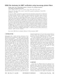
Fig. 2. Typical head-<strong>and</strong>-neck IMRT treatment plan showing conformal avoidance of the spinal cord <strong>and</strong> parotid gl<strong>and</strong>s<br />
while simultaneously delivering multiple dose prescriptions (66.5 Gy <strong>and</strong> 54.3 Gy) to the two target volumes. (A)<br />
Transverse cross-section. White line corresponds to the position of the coronal cross-section. (B) Coronal cross-section.<br />
White line corresponds to the position of the transverse cross-section. (C) DVHs of the target volumes <strong>and</strong> selected<br />
critical structures. Vertical bars indicate the prescription doses <strong>and</strong> highlight the increased dose heterogeneity often<br />
encountered as a consequence of conformal avoidance.<br />
delivery technology to result in lower cost treatment<br />
machines <strong>and</strong> improved efficiencies in planning, delivery,<br />
<strong>and</strong> treatment verification, all of which will may<br />
make a valuable contribution to lowering the overall<br />
costs of RT while improving the therapeutic results.<br />
This report is intended to create a snapshot in time of<br />
IMRT technology <strong>and</strong> its use. The intended audience is<br />
practicing physicians <strong>and</strong> medical physicists. We also<br />
believe that many of the recommendations <strong>and</strong> suggestions<br />
may be of interest to IMRT equipment manufacturers<br />
<strong>and</strong> research funding agencies. We have tried to<br />
present a balanced summary that gives some historical<br />
perspective, addresses important IMRT <strong>issues</strong>, <strong>and</strong> highlights<br />
the most relevant publications. In some sections<br />
(e.g., “Facility Planning <strong>and</strong> Radiation Safety”), the<br />
reader will find that the depth of discussion <strong>and</strong> detail
884 I. J. Radiation Oncology ● Biology ● Physics Volume 51, Number 4, 2001<br />
presented is much more than in others. This was required<br />
to support specific recommendations but made for some<br />
unevenness in the writing.<br />
IMRT HISTORICAL REVIEW<br />
The main technological precursors for the development<br />
of IMRT were the development of image-based 3D-RTP<br />
systems <strong>and</strong> the development of computer-controlled delivery<br />
systems.<br />
3D treatment planning systems<br />
Computerized RT planning was first reported 40 years<br />
ago (18). Early dedicated RTP systems depended on twodimensional<br />
(2D) contour information <strong>and</strong> calculated doses<br />
based on relatively simple 2D dose models (19, 20). This<br />
type of planning was (<strong>and</strong> continues to be) widely used<br />
throughout the RT community. The first 3D approach to<br />
treatment planning dose calculation <strong>and</strong> display is credited<br />
to Sterling et al. (21, 22), who demonstrated a computergenerated<br />
film loop that gave the illusion of a 3D view of<br />
the anatomy <strong>and</strong> the calculated isodose distribution (2D<br />
color washes) throughout a treatment volume. van de Geijn<br />
(23, 24), Cunningham (25), Beaudoin (26), <strong>and</strong> Sontag <strong>and</strong><br />
Cunningham (27) also performed early work in 3D dosecalculation<br />
models. Much of this work was eventually integrated<br />
into commercial RTP systems, but the full potential<br />
of image-based 3D treatment planning was not available to<br />
these early systems.<br />
Reinstein et al. (28) <strong>and</strong> McShan et al. (29) took the first<br />
real step toward clinically usable 3D-RTP in 1978 with the<br />
development of the beam’s-eye view display. The beam’seye<br />
view display provides the planner with a view from the<br />
perspective of the source of the radiation beam, looking<br />
down the rays of the divergent beam, <strong>and</strong> results in a view<br />
of the anatomy similar to a simulator radiograph. At the<br />
same time, the introduction of CT scanning <strong>and</strong> its use for<br />
RT significantly improved the way patient anatomy could<br />
be specified in treatment planning (30, 31). In 1983, Goitein<br />
<strong>and</strong> Abrams (32) <strong>and</strong> Goitein et al. (33) demonstrated how<br />
CT data made possible high-quality color beam’s-eye view<br />
displays <strong>and</strong> simulated radiographs computed from CT data<br />
(referred to as digitally reconstructed radiographs). Finally,<br />
between 1986 <strong>and</strong> 1989, several robust university-developed<br />
3D-RTP systems began to be implemented in clinical<br />
use (34–37).<br />
The additional development of 3D-RTP systems throughout<br />
the past 10 years, most importantly, including the commercial<br />
availability of 3D-RTP systems, has led to widespread<br />
adoption of 3D planning in many clinics. One of the<br />
keys to the acceptance of 3D-RTP throughout the community<br />
was a series of research contracts funded by the National<br />
Cancer Institute in the 1980s <strong>and</strong> early 1990s to<br />
evaluate the potential of 3D-RTP <strong>and</strong> to make recommendations<br />
to the National Cancer Institute for future research<br />
in this area (38). Each of these contracts funded a CWG to<br />
evaluate various aspects of 3D-RTP (Table 1). Important<br />
Table 1. National Cancer Institute treatment planning<br />
collaborative working group research contracts<br />
Evaluation of treatment planning for heavy particles<br />
(1982–1986)<br />
University of Pennsylvania School of Medicine <strong>and</strong> Fox<br />
Chase Cancer Center<br />
Lawrence Berkeley Laboratory <strong>and</strong> University of California<br />
Massachusetts General Hospital<br />
M. D. Anderson Cancer Center, University of Texas<br />
Evaluation of treatment planning for external beam photons<br />
(1984–1987)<br />
University of Pennsylvania School of Medicine <strong>and</strong> Fox<br />
Chase Cancer Center<br />
Memorial Sloan-Kettering Cancer Center<br />
Massachusetts General Hospital<br />
Washington University, St. Louis<br />
Evaluation of treatment planning for external beam electrons<br />
(1986–1989)<br />
University of Michigan<br />
M. D. Anderson Cancer Center, University of Texas<br />
Washington University, St. Louis<br />
Development of radiation therapy treatment planning software<br />
tools (1989–1994)<br />
University of North Carolina<br />
University of Washington<br />
Washington University, St. Louis<br />
developments <strong>and</strong> refinements in 3D planning technology<br />
came from these contracts, particularly plan evaluation software<br />
tools, such as dose–volume histograms (DVHs) (39,<br />
40), <strong>and</strong> biologic effect models, such as tumor control<br />
probability (TCP) <strong>and</strong> normal tissue complication probability<br />
(NTCP) (41, 42) models, as well as efforts to stimulate<br />
<strong>and</strong> document the <strong>current</strong> state of knowledge about these<br />
effects (43, 44). Many of these features are crucial parts of<br />
plan optimization, which is critical to IMRT. Similar collaborative<br />
groups elsewhere in the world, for example, the<br />
Computer Aided Radiotherapy project in the Nordic countries<br />
(45), also contributed significantly to the development<br />
of 3D treatment planning.<br />
Precursors to IMRT delivery systems<br />
Early IMRT delivery concepts were pioneered several<br />
decades ago. Particularly important were the early efforts of<br />
Dr. Shinji Takahashi <strong>and</strong> colleagues, from Nagoya, Japan<br />
(46). Their work illustrated some of the important concepts<br />
in both conventional 3D-CRT <strong>and</strong> IMRT delivery. Dynamic<br />
treatments were planned <strong>and</strong> delivered by Takahashi’s<br />
group using what may have been the first multileaf collimator<br />
(MLC) system. The MLC system used a mechanical<br />
control system to conform the beam aperture to the projected<br />
target shape as the machine was rotated around the<br />
patient. Another pioneering effort in CRT was conducted by<br />
the group at the Massachusetts Institute of Technology Lahy<br />
Clinic (47–49), who independently developed an asynchronous<br />
portal-defining device similar to that of Takahashi<br />
(46).<br />
The Royal Northern Hospital in Engl<strong>and</strong> also pioneered<br />
an early CRT effort (50–52). The group developed a series
IMRT: <strong>current</strong> <strong>status</strong> <strong>and</strong> <strong>issues</strong> of interest ● IMRT CWG<br />
885<br />
of cobalt-60 teletherapy machines in which the patient was<br />
automatically positioned during rotational therapy by moving<br />
the treatment couch <strong>and</strong> gantry during the radiation<br />
delivery using electromechanical systems. This was called<br />
the “Tracking Cobalt Project,” because the planning <strong>and</strong><br />
delivery system attempted to track around the path of disease<br />
spread <strong>and</strong> subsequently conform the dose distribution.<br />
Davy <strong>and</strong> Brace at the Royal Free Hospital in London<br />
extended the work in the 1970s <strong>and</strong> 1980s (53, 54).<br />
The Joint Center from the Harvard Medical School also<br />
contributed to the development of computer-controlled CRT<br />
during the 1970s (55). Unfortunately, computer technology<br />
had not yet advanced to the degree required for practical<br />
implementation of traditional 3D-CRT.<br />
Brahme (56, 57), Brahme <strong>and</strong> Ågren (58), <strong>and</strong> Cormack<br />
(59, 60) (working independently) presented many of the<br />
basic concepts related to the use of non-uniform <strong>intensity</strong><br />
distributions to create improved dose distributions in a<br />
series of reports that discussed both planning/optimization<br />
<strong>issues</strong> <strong>and</strong> treatment delivery <strong>issues</strong>. In fact, many of these<br />
ideas were involved in the design of the Sc<strong>and</strong>itronix<br />
MM50 Racetrack Microtron System, which was equipped<br />
with scanned beam control of beam <strong>intensity</strong> for both electrons<br />
<strong>and</strong> photons (61–63). However, with the exception of<br />
the continuing work by that group (e.g., the scanned MLC<br />
slit method studied by Kallman et al. [64] <strong>and</strong> Lind <strong>and</strong><br />
Kallman [65]), most of the IMRT work that followed concentrated<br />
on the plan optimization side of the IMRT problem,<br />
for instance, the work by Bortfeld et al. (66). By the<br />
mid-1990s (<strong>and</strong> before much additional discussion had occurred<br />
in the literature about IMRT delivery methods),<br />
several other kinds of delivery techniques relevant to modern<br />
IMRT had evolved. These are summarized in the following<br />
section.<br />
IMRT DELIVERY TECHNIQUES<br />
Scanned photon <strong>and</strong> electron beam IMRT<br />
The use of a computer-controlled scanned beam, available<br />
in the Sc<strong>and</strong>itronix Racetrack Microtron System,<br />
was the first modern IMRT delivery technique described<br />
in the literature (56). In this system, limited resolution<br />
beam <strong>intensity</strong> modulation is performed using computer<br />
control of the beam-steering magnets that direct the highenergy<br />
electron beam onto the X-ray target. By controlling<br />
the angle <strong>and</strong> <strong>intensity</strong> at which the electron beam<br />
strikes the X-ray target, elemental bremsstrahlung X-ray<br />
beams are created <strong>and</strong> can be placed anywhere within the<br />
radiation field using a “scan pattern” that gives beam<br />
locations <strong>and</strong> intensities. Resolution of this technique is<br />
limited, because the full-width half maximum for even<br />
the 50-MV photon beam is several centimeters. Electron<br />
beams (especially the high-energy beams from 25 to 50<br />
MeV) may also be used for IMRT with this technique, as<br />
demonstrated by Karlsson et al. (67) <strong>and</strong> Lief et al. (68,<br />
69). Because only a few institutions have had access to<br />
this technology, much more work needs to be done to<br />
fully investigate <strong>and</strong> evaluate the possibilities for<br />
scanned beam IMRT.<br />
Tomotherapy IMRT<br />
The second IMRT delivery technique described in the<br />
literature defined an approach called tomotherapy (literally<br />
“slice therapy”) by which IMRT is delivered using a<br />
narrow slit beam (70). This technique is very analogous<br />
to the tomography techniques used for CT <strong>and</strong> other such<br />
imaging systems. A temporally <strong>modulated</strong> binary mini-<br />
MLC of the type proposed by Mackie et al. (70) for<br />
tomotherapy IMRT was developed commercially (Peacock<br />
MIMiC, Nomos Corp.) (7, 71, 72). The Peacock<br />
system’s MIMiC is mounted to a conventional low-energy<br />
megavoltage medical linear accelerator, <strong>and</strong> treatment<br />
is delivered to a narrow slice of the patient using arc<br />
rotation (Fig. 3). The beam is collimated to a narrow slit<br />
(approximately 2 cm 20 cm), <strong>and</strong> beamlets of varying<br />
<strong>intensity</strong> are created by driving the MIMiC’s leaves in<br />
<strong>and</strong> out of the radiation beam’s path as the gantry rotates<br />
around the patient. A complete treatment is accomplished<br />
by serial delivery to adjoining axial slices. The clinical<br />
use of the Peacock system was first implemented at the<br />
Baylor College of Medicine in Houston, Texas (13).<br />
Since then, it has been implemented in a large number of<br />
clinics worldwide, <strong>and</strong> several other institutions have<br />
reported their experience with the Peacock IMRT system<br />
(10–12, 73). To date, this form of IMRT has been used to<br />
deliver more treatments than all other forms of IMRT<br />
combined. It has been referred to as serial tomotherapy<br />
(12) to distinguish it from the helical tomotherapy unit<br />
first proposed by Mackie et al. (70) <strong>and</strong> discussed in the<br />
next paragraph.<br />
With serial tomotherapy, extreme accuracy in the motion<br />
of the couch is necessary, because the treatments are<br />
delivered in a series of contiguous arc strips. Positioning<br />
errors of as little as 1 mm can cause dose errors on the<br />
order of 10–20% in the abutment regions (74, 75). This<br />
issue is addressed by the helical tomotherapy treatment<br />
unit depicted in Fig. 4 (70). IMRT is delivered as the<br />
patient is moved through a ring-gantry in much the same<br />
way as a helical CT study is performed. Specifically, the<br />
beamlets are created using a temporally <strong>modulated</strong> binary<br />
mini-MLC similar to the MIMiC <strong>and</strong> a low-energy linear<br />
accelerator mounted in a modified CT scanner gantry.<br />
The original proposed design included a conventional<br />
diagnostic CT system mounted on the same gantry, allowing<br />
the simultaneous acquisition of a kilovoltage CT<br />
verification scan study. A prototype helical tomotherapy<br />
IMRT system (using megavoltage CT capability) is now<br />
under development at the University of Wisconsin <strong>and</strong> is<br />
scheduled for clinical implementation in the near future<br />
(76, 77).<br />
Conventional MLC IMRT<br />
A conventional MLC under computer control can be used<br />
to deliver IMRT as follows. For a fixed gantry position, the
886 I. J. Radiation Oncology ● Biology ● Physics Volume 51, Number 4, 2001<br />
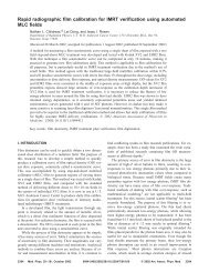
Fig. 3. Serial tomotherapy approach to IMRT. This form of IMRT uses a temporally <strong>modulated</strong> mini-MLC system such<br />
as the MIMiC (Nomos Corp.) shown here mounted to a conventional low-energy megavoltage medical linear<br />
accelerator. Treatment to a narrow slice of the patient is delivered by arc rotation. A complete treatment is accomplished<br />
by serial delivery to adjoining axial slices.<br />
opening formed by each pair of opposing MLC leaves is<br />
swept across the target volume under computer control, with<br />
the radiation beam on, to produce the desired fluence profiles<br />
(Figs. 5 <strong>and</strong> 6a). The setting of the leaf pair opening<br />
<strong>and</strong> its speed for each MLC leaf pair are determined by a<br />
technique first introduced by Convery <strong>and</strong> Rosenbloom (78)<br />
<strong>and</strong> extended by Bortfeld et al. (79), Spirou <strong>and</strong> Chui (80),<br />
<strong>and</strong> Dirkx et al. (81). This IMRT approach, referred to as<br />
the sliding window or dynamic MLC (DMLC), was first<br />
implemented for clinical use at the Memorial Sloan-Kettering<br />
Cancer Center in New York (14). The IMRT CWG<br />
recommends that this form of conventional MLC IMRT be<br />
referred to as DMLC.<br />
A second form of the conventional MLC IMRT approach<br />
uses a series of multiple segment fields, in which<br />
each field consists of a series of MLC shapes (segments<br />
or subfields) delivered from the same gantry angle, so<br />
that an <strong>intensity</strong>-<strong>modulated</strong> field <strong>intensity</strong> is delivered<br />
(Fig. 6b). The multiple segment fields are set up at<br />
selected orientations of the gantry under computer con-<br />
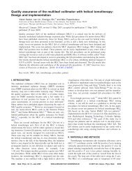
Fig. 4. Helical tomotherapy approach to IMRT. This new type treatment unit contains a low-energy megavoltage linear<br />
accelerator <strong>and</strong> a temporally <strong>modulated</strong> collimator system (similar to the Nomos MIMiC) mounted on a CT-like gantry.<br />
In addition, the system has the potential for enhanced verification using a CT X-ray source opposed by CT image<br />
detectors. The patient couch translates through the unit during treatment. (From Mackie et al. [70], with permission.)
IMRT: <strong>current</strong> <strong>status</strong> <strong>and</strong> <strong>issues</strong> of interest ● IMRT CWG<br />
887<br />
Fig. 5. DMLC technique of delivering IMRT (also referred to as the sliding window method). Dotted lines indicate<br />
positions of a leaf pair (x axis) as a function of beam-on time (y axis). As the beam is turned on (point a; see Fig. 6),<br />
both leaves move, with different speeds, from left to right. The point P begins to receive radiation when the right leaf<br />
edge moves pass over it (point b). It receives radiation until the left leaf blocks the beam (point c). By controlling the<br />
movement of the leaves <strong>and</strong> therefore the “beam-on-time” duration between b <strong>and</strong> c, one can deliver any desired<br />
<strong>intensity</strong> to point P, or any other point under this leaf pair.<br />
trol. The radiation is turned on only when the MLC<br />
leaves are stopped at each prescribed segment position.<br />
This IMRT method has been referred to as step-<strong>and</strong>-shoot<br />
or stop-<strong>and</strong>-shoot. The IMRT CWG recommends this<br />
form of conventional MLC IMRT be referred to as segmental<br />
MLC (SMLC). The leaf sequences can be determined<br />
by methods such as the one suggested by Bortfeld<br />
et al. (82) or Siochi (83). Another type of SMLC implementation<br />
makes use of multiple-shaped field segments<br />
to create the IMRT fields (15, 16). Most medical linear<br />
accelerator manufacturers are now offering SMLC–I-<br />
MRT capability, <strong>and</strong> thus, widespread implementation of<br />
this form of IMRT is anticipated during the next several<br />
years.<br />
A third conventional MLC IMRT approach, called<br />
<strong>intensity</strong>-<strong>modulated</strong> arc therapy, was described by Yu et<br />
al. (84– 86). Instead of rotating a slit-field around the<br />
patient as done with tomotherapy, <strong>intensity</strong>-<strong>modulated</strong><br />
arc therapy uses multiple irregular fields shaped with a<br />
conventional MLC during gantry rotation. Intensity-<strong>modulated</strong><br />
arc therapy is planned as a sequence of static<br />
fields, every 5–10° apart, but delivered with multiple<br />
superimposing arcs. Within each arc, the MLC shape is<br />
continuously changed as a function of gantry angle on the<br />
basis of the results of optimization, such that the cumulative<br />
<strong>intensity</strong> distribution leads to the desired dose<br />
distribution. This IMRT approach was first implemented<br />
for clinical use at the University of Maryl<strong>and</strong> (87).<br />
Physical modulator (compensating filter) IMRT<br />
Several groups have reported on the use of a physical<br />
modulator to deliver IMRT (88–93). Filters can be designed<br />
using a 3D-RTP system to calculate the required<br />
thicknesses (along ray lines using an effective attenuation<br />
coefficient for the filter material <strong>and</strong> dose–ratio parameters<br />
for effective depths) to generate the desired IMRT<br />
fluence profile when the filter is placed in the radiation<br />
beam. Stein et al. (89) reported on the use of IMRT<br />
physical modulators fabricated using low–melting-point<br />
alloy poured into foam molds, which are cut using a<br />
computer-controlled cutter. In addition, Dubal et al. (94)<br />
recently reported on an IMRT physical modulator approach<br />
for the treatment of breast cancer. The physical<br />
modulator IMRT method has some advantages, including<br />
higher resolution in the direction normal to the leaf<br />
motion, higher precision compared with some MLC approaches,<br />
simpler quality assurance (QA), <strong>and</strong> no matchline<br />
problems. On the other h<strong>and</strong>, it has a relatively<br />
cumbersome <strong>and</strong> time-consuming manufacturing process<br />
<strong>and</strong> one must enter the treatment room to change the filter<br />
for each gantry orientation, thus increasing the time<br />
allocated for patient treatment. This approach will likely
888 I. J. Radiation Oncology ● Biology ● Physics Volume 51, Number 4, 2001<br />
Fig. 6. (A) Intensity profile delivered by the leaves’ paths of Fig. 5 (replotted here as dotted lines). In practice, a<br />
“leaf-sequencing” algorithm is used to translate the desired <strong>intensity</strong> profiles into a computer data file of the leaf<br />
positions as a function of MUs. (B) SMLC technique of delivering IMRT (also referred to as the step-<strong>and</strong>-shoot<br />
method). In the “step” phase, the leaves travel to discrete positions, then the radiation beam turns on in the “shoot” phase<br />
(i.e., alternate MLC movement <strong>and</strong> radiation delivery). The result is discrete <strong>intensity</strong> levels, the number of which<br />
depends on the “step” number.<br />
serve only as an intermediate step in some institutions<br />
before other approaches to IMRT are adopted.<br />
Robotic linear accelerator IMRT<br />
The use of a small x-b<strong>and</strong> linear accelerator, mounted on<br />
an industrial robot, a concept first developed for radiosurgery<br />
(95), has also been proposed as a treatment delivery<br />
device for sophisticated IMRT (96, 97). The robot would<br />
provide the capability for aiming beamlets with any orientation<br />
relative to the target volume, thus giving this IMRT<br />
approach more flexibility than any of those previously discussed.<br />
The treatment is specified by the trajectory of the<br />
robot <strong>and</strong> by the number of monitor units (MUs) delivered<br />
at each robotic orientation. This technology is not widely<br />
available at present, <strong>and</strong> significant research <strong>and</strong> development<br />
are needed to explore its use for IMRT.<br />
COMPUTER OPTIMIZATION<br />
With the advent of computers, work on automated methods<br />
of plan optimization was initiated by numerous investigators,<br />
but did not result in widespread use. However, with<br />
the development of conventional 3D-CRT, interest in computer<br />
optimization was renewed, because the amount of<br />
image <strong>and</strong> graphic data the planner must deal with increased<br />
significantly, as did the computer hardware capabilities <strong>and</strong><br />
software sophistication. In addition, as previously indicated,<br />
IMRT requires a method of designing optimum non-uniform<br />
beam <strong>intensity</strong> profiles, a task for which computer<br />
optimization is indispensable. The use of computer optimization<br />
methods for IMRT plan design has been referred to<br />
inverse planning to distinguish it from the more iterative<br />
<strong>and</strong> interactive forward planning used in the planning of<br />
conventional 3D-CRT. During the past decade, major<br />
progress in computerized optimization for use in IMRT has<br />
been accomplished, led by Bortfeld et al. (66, 79, 98),<br />
Brahme (57, 99), Webb (100–103), Mohan et al. (104, 105),<br />
<strong>and</strong> others (71, 106). Other references of IMRT optimization<br />
are provided in the textbook by Webb (5).<br />
In forward treatment planning, the beam geometry (beam<br />
orientation, shape, modifier, beam weights, etc.) is first<br />
defined, followed by calculation of the 3D dose distribution.<br />
After qualitative review of the dose distribution by the<br />
treatment planner <strong>and</strong>/or radiation oncologist, plan improvement<br />
is performed by modifying the initial geometry<br />
(e.g., changing the beam weights <strong>and</strong>/or modifiers, adding<br />
another beam), to improve the target dose coverage <strong>and</strong>/or<br />
decrease the dose in the organs at risk. This forward planning<br />
process is repeated until a satisfactory plan is generated.<br />
In inverse treatment planning, the focus is on the<br />
desired outcome (e.g., a specified dose distribution or even<br />
TCP <strong>and</strong> NTCPs) rather than how the outcome is going to<br />
be achieved. The user of the system specifies the goals; the<br />
computer (optimization system) then adjusts the beam pa-
IMRT: <strong>current</strong> <strong>status</strong> <strong>and</strong> <strong>issues</strong> of interest ● IMRT CWG<br />
889<br />
Fig. 7. Limitations of dose–volume-based optimization objective functions. (A) DVH for an organ at risk in which a<br />
criterion has been specified so that no more than 25% of the volume is to receive 50 Gy. All three DVHs shown meet<br />
this criterion; however, the DVH represented by the solid curve clearly causes the least damage. (B) This limitation can<br />
be overcome by specifying the entire DVH. However, different treatment techniques can result in dose distributions that<br />
could produce equivalent damage to a particular organ at risk, but have significantly different results for other organs<br />
at risk <strong>and</strong>/or the tumor (i.e., only one of these DVHs may be optimal so far as other organs <strong>and</strong> the tumor are<br />
concerned).<br />
rameters (mainly the intensities) iteratively in an attempt to<br />
achieve the desired outcome. After review of the computeroptimized<br />
dose distribution, some modification of the desired<br />
outcome <strong>and</strong> adjustment of the relative importance of<br />
each end point might be needed if the physician is not<br />
satisfied with the dose to the target volume or organs at risk.<br />
Thus, one sees that both forward <strong>and</strong> inverse planning<br />
involve iteration to find the best plan.<br />
To better underst<strong>and</strong> the inverse planning method (computer<br />
optimization), it is helpful to separate the process into<br />
two components: (1) specification of optimization criteria<br />
(objective function <strong>and</strong> constraints) <strong>and</strong> (2) the optimization<br />
(search) algorithm used.<br />
Objective functions<br />
For inversely planned IMRT, the clinical objectives are<br />
specified mathematically in the form of an objective function<br />
(also called the score function or cost function). Computer<br />
optimization techniques are then used to determine the<br />
beam parameters (<strong>current</strong>ly, often limited to the beamlet<br />
weights) that will most closely achieve the desired solution.<br />
The value of the objective function is the putative index of<br />
the goodness of the treatment plan. The term score or cost<br />
is often used to denote this value. Thus, the aim of optimization<br />
is to minimize (or maximize, depending on the choice<br />
of objective function) the score.<br />
Some of the earlier attempts to optimize RT plans used<br />
objective functions based on dose distributions features (66,<br />
98, 107–114). For example, one could choose to maximize<br />
the minimal dose to the target volume subject to a constraint<br />
on the maximal dose to certain organs at risk. For simplicity,<br />
many investigators have used purely dose-based criteria<br />
for optimizing IMRT as well. However, it is recognized<br />
that, in general, the response of the tumor <strong>and</strong> normal<br />
t<strong>issues</strong> is a function of not only the radiation dose but also<br />
(to varying degrees depending on the tissue type) the volume<br />
subjected to each level of dose.<br />
At present, most IMRT optimization systems use dosebased<br />
<strong>and</strong>/or dose–volume-based criteria. One method commonly<br />
used to create dose-based <strong>and</strong> dose–volume objective<br />
functions is based on minimizing the variance of the dose<br />
relative to the prescribed dose for the target volumes or dose<br />
limits for the organs at risk. Variance is defined as the sum<br />
of the squares of the differences between the calculated dose<br />
<strong>and</strong> the prescribed dose or dose limit. Thus, a typical dosebased<br />
or dose–volume-based objective function is the sum<br />
of the variance terms representing each anatomic structure<br />
multiplied with appropriate penalty factors (i.e., importance<br />
factors). This approach is sometimes referred to as a quadratic<br />
objective function.<br />
If the physician knows the dose–volume relationships<br />
that are desired for the organs of interest, dose–volumebased<br />
objective functions may produce more appropriate<br />
plans than dose-based criteria. However, dose–volume criteria<br />
also have limitations (104, 115). Consider, for instance,<br />
an organ at risk for which the criterion has been<br />
specified so that no more than 25% of the volume is to<br />
receive 50 Gy (Fig. 7a). All three DVHs (Fig. 7) meet this<br />
criterion; however, the DVH represented by the solid curve<br />
clearly causes the least damage. One can argue that this
890 I. J. Radiation Oncology ● Biology ● Physics Volume 51, Number 4, 2001<br />
limitation can be overcome by specifying multiple dose–<br />
volume constraints or even the entire DVH. However, multiple<br />
DVHs (in fact an infinite number of them) could lead<br />
to an equivalent dose response for a particular organ (Fig.<br />
7b). When this happens, DVHs usually cross each other as<br />
shown in Fig. 7. Optimization based on each of these<br />
biologically equivalent DVHs would, in general, lead to<br />
different dose responses in other organs <strong>and</strong> the tumor. Only<br />
one of the DVHs may be optimum so far as the other organs<br />
<strong>and</strong> tumor are concerned. Thus, constraining the search to a<br />
single DVH for an anatomic structure may miss the overall<br />
optimal solution.<br />
Another weakness of quadratic (i.e., variance) dose- <strong>and</strong><br />
dose–volume-based objective functions, as typically used, is<br />
that neither adequately represents the nonlinear response of<br />
tumors or normal structures to dose, especially for arbitrary<br />
inhomogeneous dose distributions. For instance, if a single<br />
voxel or a small number of voxels in a tumor receive a very<br />
low dose, it would not have a significant effect on the IMRT<br />
plan score. However, the tumor control probability would<br />
be greatly diminished as a result of the cold spot. Stated in<br />
a different way, for dose- or dose–volume-based objective<br />
functions, the penalty imposed for the failure to achieve the<br />
prescribed dose is proportional to the dose difference (or the<br />
square of the difference), rather than to the loss of tumor<br />
control, which would be more appropriate. Such limitations<br />
have led a number of investigators to consider models for<br />
predicting biologic <strong>and</strong> dose–response indexes that could be<br />
used to supplement dose <strong>and</strong> dose–volume criteria (104,<br />
105, 116–122). One way to cast the objective function in<br />
terms of the clinical <strong>and</strong> biologic criteria is to use indexes<br />
such as TCP, NTCPs, <strong>and</strong> the equivalent uniform dose<br />
(122). Objective functions based on biologic <strong>and</strong> dose–<br />
response indexes for IMRT optimization do not represent<br />
the state-of-the-art of IMRT clinical practice. They are a<br />
topic of on-going investigations <strong>and</strong> are not discussed further<br />
in this report.<br />
In addition to dose, dose–volume, <strong>and</strong> dose–response<br />
information, it may be necessary to include other important<br />
factors in the objective function, such as plan complexity<br />
<strong>and</strong> other nondosimetric factors that affect how the patient<br />
should be treated. In a method proposed by Kessler et al.<br />
(123) <strong>and</strong> Fraass et al. (15), the objective function is created<br />
from the combination of many different components, called<br />
costlets. This very general method can combine dose, DVH<br />
point, TCP, <strong>and</strong> NTCP-related costlets into an overall score<br />
function. This type of construct may have the flexibility<br />
needed for a clinically relevant score function, but it also<br />
shares all the disadvantages of each of the individual costlets<br />
used.<br />
In summary, in the <strong>current</strong> state-of-the-art, dose–volumebased<br />
objective functions have become an accepted st<strong>and</strong>ard.<br />
In general, they produce satisfactory plans, <strong>and</strong> their<br />
continued use is recommended until dose–response-based<br />
objective functions are shown to have a clear <strong>and</strong> significant<br />
advantage. Many <strong>issues</strong> regarding IMRT computer optimization<br />
need additional investigation. Objective functions<br />
that are more clinically relevant need to be defined <strong>and</strong> their<br />
parameters determined for each combination of treatment<br />
site, IMRT delivery technique, <strong>and</strong> other clinical factors<br />
(i.e., establishment of IMRT class solutions). The determination<br />
of parameters of an objective function (whether<br />
dose–volume-based or dose–response-based) that may be<br />
applied to all patients presenting with a specific class of<br />
clinical indications is an important, but at the same time a<br />
daunting task, especially when the number of such parameters<br />
is large (multiple organs <strong>and</strong> multiple dose–volume<br />
constraints per organ). Research is needed to systematize<br />
the determination of these parameters. Furthermore, the<br />
limitations of the dose-, dose–volume-, <strong>and</strong> dose–responsebased<br />
objective functions need to be determined. Most<br />
importantly, accurate dose–volume-response data for each<br />
organ <strong>and</strong> tumor type need to be accumulated prospectively<br />
<strong>and</strong> analyzed to develop more dependable dose–responsebased<br />
optimization criteria.<br />
Computer optimization (search) process<br />
The process of the optimization of <strong>intensity</strong> distributions<br />
may be carried out using one of several mathematical formalisms<br />
<strong>and</strong> algorithms (referred to as optimization or<br />
search methods). The choice may depend on the nature of<br />
the objective function used, on the scope <strong>and</strong> number of<br />
parameters to be optimized, the accessibility of each particular<br />
method, <strong>and</strong> individual preference. In the pioneering<br />
work on IMRT optimization, Brahme et al. (99, 124) used<br />
“radiation kernels” to first produce optimum dose distributions<br />
<strong>and</strong> then, using the inverse back projection technique<br />
borrowed from image reconstruction methods, to obtain<br />
<strong>intensity</strong> distributions that would lead to the best approximation<br />
of the optimum dose distribution. Since then, a large<br />
variety of methods have been evaluated. They fall into two<br />
basic categories: gradient methods <strong>and</strong> stochastic methods.<br />
The following is qualitative explanation of how a typical<br />
optimization algorithm works. (This explanation is specifically<br />
for gradient methods, but, with some exceptions discussed<br />
later, applies to stochastic methods as well.) Each<br />
beamlet is traced from the source of radiation through the<br />
patient. In general, only the beamlets that pass through the<br />
target volume need to be traced, plus a small margin around<br />
the target volume that is assigned to ensure that the lateral<br />
loss of scattered radiation does not compromise the treatment.<br />
All other beamlets are set to a weight of 0. The<br />
patient’s 3D description is divided into small volume elements<br />
or voxels. The dose in each voxel is calculated for an<br />
initial set of beamlet weights. The resulting dose distribution<br />
is used to compute the value of the objective function<br />
(i.e., the score). If the change in beamlet weight results in an<br />
improved score, the proposed change in weight of that<br />
beamlet is accepted, <strong>and</strong> if not, the change is rejected<br />
(depending on the search method, see below). Because the<br />
improvement in the plan at each point comes from beamlets<br />
from many different directions <strong>and</strong> each beamlet affects<br />
many points, only relatively small changes in beamlet<br />
weight are permitted at one time. This process is repeated
IMRT: <strong>current</strong> <strong>status</strong> <strong>and</strong> <strong>issues</strong> of interest ● IMRT CWG<br />
891<br />
Fig. 8. Objective functions with (A) a single minimum <strong>and</strong> (B) multiple minima.<br />
for all the beamlets. At the end of each complete cycle (an<br />
iteration), a small improvement in the treatment plan presumably<br />
results. The new pattern of beamlet intensities is<br />
then used to calculate a new dose distribution <strong>and</strong> a new<br />
score of the objective function, which is then used as the<br />
basis for additional improvement in the next cycle. This<br />
iterative process continues until no further improvement<br />
takes place; at that time, the optimum plan is assumed to<br />
have been achieved.<br />
Gradient techniques are by far the fastest computationally<br />
(106, 125–128). However, the use of a gradient technique<br />
assumes that there is a single extremum (a minimum<br />
or a maximum, depending on the form of the objective<br />
function) (Fig. 8). This is the case for a quadratic objective<br />
function (based on variance of dose) when only beamlet<br />
weights are optimized. For other cases, it may be necessary<br />
to determine whether multiple extrema exist, <strong>and</strong> whether<br />
these multiple extrema have an impact on the quality of the<br />
solutions found. Multiple extrema have been found to exist<br />
when beam directions are optimized <strong>and</strong> when dose–response-based<br />
objective functions are used to optimize the<br />
weights of uniform beams (104, 129, 130). One can expect<br />
that multiple minima also exist when dose–response-based<br />
objective functions are used to optimize IMRT plans. Using<br />
simple schematic examples, it has also been shown that<br />
multiple minima exist when dose–volume-based objectives<br />
are used (131). When multiple extrema exist, the gradient<br />
search methods will converge to the nearest extremum. The<br />
treatment plan corresponding to this extremum may be far<br />
from the best solution possible <strong>and</strong> may be totally unsatisfactory.<br />
However, although this may be the case in theory,<br />
the existence of multiple minima has not yet been found to<br />
be a serious impediment in dose–volume- or dose–responsebased<br />
optimization of IMRT plans using gradient techniques.<br />
If multiple minima are found to be a factor, some<br />
form of stochastic optimization technique (see next paragraph)<br />
may need to be considered.<br />
The most commonly used stochastic technique is simulated<br />
annealing or its variation fast simulated annealing<br />
(102–104, 111, 129) Other forms of stochastic approaches<br />
such as “genetic algorithms” have also been proposed (132).<br />
In principle, the simulated annealing technique <strong>and</strong> other<br />
stochastic approaches allow the optimization process to<br />
escape from the local extrema traps <strong>and</strong> thus find the global<br />
extrema, as shown in Fig. 8; however, this is true only if a<br />
large number of configurations are tested. Practically, there<br />
is no guarantee that the absolute optimum will be found,<br />
only that the best solution among those examined will be<br />
found. Furthermore, stochastic techniques tend to be relatively<br />
slow. Nevertheless, some commercial systems have<br />
implemented the simulated annealing approach for IMRT<br />
optimization (72).<br />
In summary, gradient search algorithms are fast <strong>and</strong> have<br />
so far been able to produce satisfactory results. Although<br />
multiple extrema are known to exist, their existence has not,<br />
in general, been shown to be an impediment in achieving<br />
satisfactory solutions. Continuing research is needed to determine<br />
whether the use of slow stochastic methods will<br />
lead to a significant improvement in the results. In the<br />
meantime, it is recommended that, for efficiency reasons,<br />
gradient methods be used in routine clinical practice of<br />
IMRT.<br />
Leaf sequence generation<br />
Most <strong>current</strong> IMRT planning systems produce a description<br />
of the beam <strong>intensity</strong> patterns. These <strong>intensity</strong> distributions<br />
are then used in a process called leaf sequencing, in<br />
which an algorithm attempts to define the shapes (for SML-<br />
C–IMRT) or trajectories (for DMLC–IMRT) of the MLC<br />
leaves required to create a deliverable <strong>intensity</strong> distribution<br />
that gives an <strong>intensity</strong> distribution as close as possible to the<br />
distributions obtained from the optimization system. Methods<br />
for SMLC–IMRT leaf sequencing have been described<br />
by Galvin et al. (133), Bortfeld et al. (82), Boyer <strong>and</strong> Yu<br />
(134), <strong>and</strong> others. Use of dynamic leaf motion has been<br />
described by Spirou <strong>and</strong> Chui (80), Dirkx et al. (81), <strong>and</strong><br />
others. Leaf sequencing for tomotherapy is particularly simple,<br />
because the leaves are rapidly driven open or closed
892 I. J. Radiation Oncology ● Biology ● Physics Volume 51, Number 4, 2001<br />
with the <strong>intensity</strong> through the leaf position proportional to<br />
the time it is open.<br />
To deliver a predictable dose distribution, a number of<br />
other refinements are needed in an accurate MLC leafsetting<br />
sequence to account for effects such as field flatness,<br />
the relative output factor of the MLC leaves, penumbra,<br />
phantom scatter effects, leaf leakage, rounded leaf ends, <strong>and</strong><br />
back scatter into the transmission ion chamber (80). Prominent<br />
among these is the consideration of leaf leakage. The<br />
leakage dose delivered along the profile can be calculated<br />
once a first approximation of the sequence has been computed.<br />
This leakage is a low-dose profile. The leakage-dose<br />
profile can be subtracted from the desired profile <strong>and</strong> the<br />
leaf-setting sequence recomputed using the corrected profile.<br />
Other modifications of the leaf-setting sequence can<br />
correct for the tongue-<strong>and</strong>-groove effect (135, 136). Integration<br />
of more detailed delivery-related effects <strong>and</strong> limitations<br />
into the overall optimization process is an area requiring<br />
continued research <strong>and</strong> development.<br />
DOSE DISTRIBUTION AND MU CALCULATIONS<br />
FOR IMRT<br />
The calculation of the dose distribution associated with<br />
IMRT delivery is a critical aspect of the IMRT optimization<br />
<strong>and</strong> delivery processes. The calculated dose distribution<br />
from each c<strong>and</strong>idate set of plan parameters is evaluated at<br />
each iteration of the optimization process, <strong>and</strong> the objective<br />
function values (costs or scores) for the iterative optimization<br />
are typically obtained by analysis of the dose distribution.<br />
After the optimized plan is obtained, another dose<br />
calculation/optimization procedure, called leaf sequencing,<br />
is performed to account for the dose calculation or physical<br />
limitations in the delivery script. Typically, the actual MUs<br />
used to deliver each of the IMRT fields are calculated as<br />
part of this process, because the leaf-sequence corrections<br />
may depend on the number of MUs. Often, the results of the<br />
leaf-sequencing algorithm are input again into a dose-calculation<br />
algorithm to generate a dose distribution that<br />
should represent the actual dose distribution delivered to the<br />
patient. In each of these steps, the speed, accuracy, <strong>and</strong><br />
generality of the dose-calculation algorithms used for each<br />
step must be considered, because limitations may affect the<br />
true accuracy of the results.<br />
During the iterative optimization part of the process,<br />
severe dem<strong>and</strong>s are placed on the dose-calculation algorithm.<br />
First, the number of iterations through the dose<br />
calculation (for different beamlet <strong>intensity</strong> distributions)<br />
may range from hundreds (for gradient search methods) to<br />
tens or hundreds of thous<strong>and</strong>s (for the stochastic methods<br />
such as simulated annealing). Therefore, the speed of the<br />
dose-calculation method can often be crucial, <strong>and</strong> severe<br />
approximations or limitations are often imbedded in the<br />
calculation algorithm used within the optimization loop. A<br />
second limitation is that most <strong>current</strong> dose-calculation algorithms<br />
used within the optimization usually consider the<br />
<strong>intensity</strong> or fluence distribution to be an ideal set of beamlet<br />
intensities, <strong>and</strong> rarely (if ever) are any of the realistic<br />
limitations associated with the delivery of those <strong>intensity</strong><br />
distributions included in the calculation results. A third<br />
limitation involves the number of dose points inside the<br />
volume of interest that are actually calculated, because<br />
increasing the number of points significantly reduces the<br />
speed of the dose calculation for each iteration; this leads to<br />
the potential for resolution problems that often cause inaccurate<br />
evaluation results (in the objective function) rather<br />
than just limiting the spatial resolution of the dose distribution,<br />
as was the case when the isodose lines were the main<br />
evaluation criteria for a plan. Finally, given the ability of the<br />
optimization algorithm <strong>and</strong> IMRT delivery to react to small<br />
influences within the field (i.e., the accuracy of the dosecalculation<br />
algorithm with respect to <strong>issues</strong> such as heterogeneities<br />
within the patient, density corrections, surface<br />
dose/buildup region accuracy, patient setup uncertainty, <strong>and</strong><br />
organ motion), as well as the potential for use of small<br />
“beamlets” that are much smaller than normally used radiation<br />
fields, the inaccuracy of the dose-calculation algorithm<br />
in any of the above situations may lead to significant<br />
reductions in the quality of the calculated-dose distribution<br />
<strong>and</strong> the plan that results from the optimization. Therefore,<br />
significant attention must be given to the various dosecalculation<br />
compromises <strong>and</strong> decisions that are incorporated<br />
in any optimization or inverse planning system.<br />
Calculation algorithm types<br />
From the perspective of IMRT, four types of dose-calculation<br />
algorithms may be described. Many calculation algorithms<br />
can be classified broadly as broad beam algorithms,<br />
because they are intended for use with flat or wedged fields<br />
<strong>and</strong> do not really apply to the variable <strong>intensity</strong> situation<br />
used for IMRT. These algorithms are usually not appropriate<br />
for the significantly more complex <strong>intensity</strong> distributions<br />
often used in IMRT <strong>and</strong> should be used only with great care.<br />
For each IMRT beam, the <strong>intensity</strong> pattern for the beam can<br />
be modeled as a 2D map of energy fluence incident on a<br />
patient. The map can be divided into discrete beam elements<br />
called beamlets (sometimes called bixels or rays). A beamlet<br />
could correspond to a finite region of a compensator, a<br />
portion of the travel of a leaf of a conventional MLC, or a<br />
leaf of a temporally <strong>modulated</strong> binary mini-MLC. The dose<br />
distribution resulting from the <strong>intensity</strong> or fluence through<br />
each beamlet must then be calculated.<br />
One of the most commonly used IMRT dose-calculation<br />
algorithm types can be described as a simple pencil beam<br />
method <strong>and</strong> is generally part of a broader class of correction-based<br />
dose-calculation algorithms (137, 138). Correction-based<br />
models depend on empirically measured data for<br />
a limited number of situations <strong>and</strong> then correct the dose<br />
distribution for the presence of the beam modifiers, contour<br />
corrections, tissue heterogeneities, <strong>and</strong> other <strong>issues</strong> encountered<br />
in treatment planning of real patients. A good example<br />
of this type of model is the finite-size pencil beam algorithm<br />
described by Bourl<strong>and</strong> <strong>and</strong> Chaney (139) <strong>and</strong> extended by<br />
Ostapiak et al. (140). The dose resulting from each individ-
IMRT: <strong>current</strong> <strong>status</strong> <strong>and</strong> <strong>issues</strong> of interest ● IMRT CWG<br />
893<br />
Fig. 9. Set of central axis 4 MV X-ray depth–dose curves computed for a variety of field sizes in a water phantom with<br />
a lung-equivalent slab (0.3 g/cm 3 ). The 1 cm 1cmfield size is typical of the pencil beam size used in IMRT.<br />
ual beamlet is calculated using the product of the inverse<br />
square law, the Tissue-Maximum Ratio (TMR) for the pencil<br />
beam, an off-axis ratio, the appropriate output factor, the<br />
MUs delivered, <strong>and</strong> various constants or other correction<br />
factors. Models with this kind of simplicity offer significant<br />
speed advantages for use in the optimization code but have<br />
varying limitations in accuracy.<br />
A third kind of calculation algorithm is based on the<br />
kernel-based models, which directly compute the dose in a<br />
phantom or patient. Typical of this type of model are<br />
convolution/superposition algorithms that can take into account<br />
beam energy, geometry, beam modifiers, patient contour,<br />
<strong>and</strong> electron density distribution (141–145), although<br />
there are also pencil beam approaches (146) that bridge the<br />
gap between the empirically based correction models (like<br />
the finite-size pencil beam) <strong>and</strong> true kernel-based convolution<br />
models. Unlike correction-based methods, kernel-based<br />
approaches do not first compute the dose in a water phantom<br />
<strong>and</strong> correct the water dose for the treatment circumstances.<br />
Both the convolution method <strong>and</strong> the Monte Carlo method<br />
(discussed below) compute the dose per unit energy fluence<br />
(or fluence) incident on the patient.<br />
Convolution methods are capable of accounting for electronic<br />
disequilibrium effects (141–145) <strong>and</strong> may more accurately<br />
deal with inhomogeneities <strong>and</strong> other complex aspects<br />
of IMRT dose calculations than the models described<br />
above. Fig. 9 illustrates the potential for large differences in<br />
the dose due to inhomogeneities for small beamlets. In this<br />
example (water phantom with a lung-equivalent slab), the<br />
depth-dose for the 10 cm 10 cm field is only slightly<br />
perturbed because of the reduced attenuation of the primary<br />
photons. However, the depth-dose for the 5 cm 5cmfield<br />
has a reduced dose because of the streaming of electrons<br />
laterally, <strong>and</strong> the 1 cm 1cmfield, typical of the area of<br />
an IMRT beamlet, shows severe perturbation because of<br />
electronic disequilibrium. The perturbing effect of electronic<br />
disequilibrium increases with the beam energy (147,<br />
148). It is evident from this simple example that the development<br />
of IMRT plans requires a dose-calculation method<br />
that can accurately predict electronic disequilibrium effects.<br />
Although it is clear that the improved dose-calculation<br />
accuracy afforded by the convolution-type calculations may<br />
be important for IMRT, the long calculation times make this<br />
difficult. Currently, many optimization approaches do not<br />
use these more accurate calculations, or only use them at the<br />
end of the optimization to calculate the final delivered dose<br />
distribution. Only one group has reported the use of full<br />
convolution/superposition calculations within the optimization<br />
iteration loop (149).<br />
Recently, significant progress has been made in the development<br />
of Monte Carlo calculation algorithms for photon<br />
beams that are fast enough to compete with other <strong>current</strong><br />
methods (150–153). In several situations, the Monte Carlo<br />
method is likely to be even more accurate than the convolution<br />
method (154). For example, multiple scatter (second<br />
<strong>and</strong> higher order scatter) may be perturbed near the surface<br />
of a patient <strong>and</strong> the Monte Carlo method may be able to<br />
account for this as long as the number of simulated particles<br />
(called histories) is sufficient to compute the multiple scattered<br />
photon dose accurately. In addition, the “density scaling”<br />
method (154) used by the superposition/convolution<br />
methods to correct for heterogeneities may not be adequate<br />
for primary electrons set in motion, especially in higher<br />
atomic number materials, such as bone or metal prostheses,
894 I. J. Radiation Oncology ● Biology ● Physics Volume 51, Number 4, 2001<br />
in which the electrons may be scattered laterally considerably<br />
more than in water. Direct Monte Carlo simulation may<br />
be the only option for achieving accurate dose computations<br />
in these complex situations. However, the application of<br />
Monte Carlo methods to optimization for IMRT is an area<br />
that requires much more work before relevant results will be<br />
available.<br />
Important <strong>issues</strong> for IMRT dose calculations<br />
The following features should be explicitly modeled in all<br />
IMRT dose-calculation algorithms to achieve reasonable<br />
accuracy, although, at present, many IMRT dose-calculation<br />
algorithms compromise many of these <strong>issues</strong>:<br />
Finite source size<br />
Extrafocal radiation generated mainly in the primary collimator<br />
<strong>and</strong> the field-flattening filter (155)<br />
Beam spectrum <strong>and</strong> the change in spectrum with lateral<br />
position<br />
Beam <strong>intensity</strong> variation across the field (e.g., the beam<br />
horns)<br />
Transmission through independent or dependent collimator<br />
jaws <strong>and</strong> MLC (156)<br />
MLCs vs. Cerrobend blocks (with blocking tray)<br />
Wedges <strong>and</strong> compensators (including the spectral hardening<br />
they produce)<br />
Dynamic wedge<br />
Scatter outside the field (related to extrafocal radiation<br />
[155])<br />
Electron contamination<br />
Delivery specific limitations <strong>and</strong> <strong>issues</strong><br />
All the above <strong>issues</strong> may influence the accuracy of the<br />
proposed optimized IMRT plans. The clinical importance of<br />
each of these factors within the optimization context should<br />
be the subject of further research.<br />
Within the context of optimization, dose calculation<br />
speed is a critical issue. Currently, any algorithm will make<br />
speed vs. accuracy compromises to allow the optimization<br />
algorithm to work within a reasonable time. However, for<br />
any dose-calculation algorithm, any approximation that<br />
compromises dose-calculation accuracy for the sake of<br />
speed must be validated or characterized, so that the implications<br />
of the compromises on the clinical results will be<br />
understood. During the coming years, improvements in<br />
calculation speed <strong>and</strong> accuracy are expected. For example,<br />
the time required to perform the Monte Carlo simulation<br />
depends only on the number of histories through a region<br />
<strong>and</strong> not on the number of beams computed. Thus, for IMRT,<br />
which is calculated using many independent beam directions,<br />
Monte Carlo calculation times may not be too unreasonable,<br />
because the number of histories per beam can be<br />
reduced in proportion to the number of beams simulated<br />
(157). For the coming years, the investigation of the<br />
tradeoffs <strong>and</strong> implications of dose-calculation approximations<br />
will be an important research area.<br />
MU calculations for IMRT<br />
Conventional MU calculation methods were designed for<br />
computing the dose from measured dose information. These<br />
methods perform very well when the beam is rectangular<br />
<strong>and</strong> incident perpendicular to the water phantom. They<br />
perform less well when there are beam modifiers like compensators,<br />
contour corrections, <strong>and</strong> heterogeneities. In<br />
IMRT, the beam shapes are unlike anything used conventionally<br />
(158). Rather than lacking electronic equilibrium<br />
only near the surface <strong>and</strong> the boundaries of fields, most of<br />
the field is in a state of disequilibrium. Thus, methods such<br />
as the Clarkson summation technique <strong>and</strong> off-axis factor<br />
may not be accurate for IMRT fields.<br />
One of the most difficult problems with correction-based<br />
techniques is the separation of scatter from the phantom<br />
from scatter from the head of the machine. This is not a<br />
problem for the convolution <strong>and</strong> Monte Carlo methods,<br />
which implicitly compute the contribution of phantom scatter,<br />
leaving only the contribution of head scatter to determine.<br />
In many implementations, the kernel-based algorithms<br />
determine the energy fluence per MU that is emitted<br />
by the machine <strong>and</strong> is thereby incident on the patient (137,<br />
159). There are beginning to be accurate ways to model the<br />
emitted energy fluence; however, it is also possible to infer<br />
it from dose measurements without requiring the measurement<br />
of the dose with a buildup cap or a miniphantom<br />
(160–163). None of these methods is <strong>current</strong>ly accepted as<br />
the st<strong>and</strong>ard, <strong>and</strong> most institutions that treat patients with<br />
IMRT routinely confirm the actual MU used for clinical<br />
treatments for each patient. It is clear, certainly, that more<br />
work in the area of MU calculations for IMRT is needed.<br />
Recommendations: IMRT dose calculations<br />
The following list summarizes the IMRT CWG recommendations<br />
regarding dose-calculation algorithms for<br />
IMRT:<br />
1. Kernel-based models <strong>and</strong> Monte Carlo simulation should<br />
be further developed for use in dose computation for<br />
IMRT. Both methods intrinsically model the energy fluence<br />
incident on a patient during IMRT <strong>and</strong> take into<br />
account the transport of secondary particles. Both methods<br />
account for electronic disequilibrium, which occurs<br />
even at the central axis in finite-size pencil beams. Additional<br />
research to make accurate convolution/superposition<br />
<strong>and</strong> Monte Carlo algorithms suitable for routine<br />
clinical use should be encouraged.<br />
2. The model of the incident beam should take into account<br />
many effects, including the finite size of the source,<br />
extrafocal radiation, disequilibrium effects in inhomogeneities,<br />
changes in the surface dose distribution, transmission<br />
through collimation systems, <strong>and</strong> many other<br />
effects.<br />
3. Traditional MU calculations based on broad-beam data,<br />
such as tissue-phantom ratios, may be inappropriate for<br />
IMRT. Instead, accurately measured pencil beams or<br />
kernel-based methods that compute the dose per incident
IMRT: <strong>current</strong> <strong>status</strong> <strong>and</strong> <strong>issues</strong> of interest ● IMRT CWG<br />
895<br />
energy fluence <strong>and</strong> are calibrated by measurements to<br />
obtain the energy fluence per MU produced by the beam<br />
in reference conditions appear to be better suited for<br />
IMRT. However, much work in this area is still required.<br />
IMRT ACCEPTANCE TESTING,<br />
COMMISSIONING, AND QA<br />
In many ways, the <strong>issues</strong> that must be addressed during<br />
acceptance testing <strong>and</strong> commissioning of IMRT planning<br />
<strong>and</strong> delivery systems are analogous to those necessary for<br />
conventional 3D-CRT. 3D-RTP systems, for example, have<br />
in common the requirement for consistently keeping track<br />
of patient-specific information, such as name <strong>and</strong> identification<br />
number, patient image data sets, contours, <strong>and</strong> dose<br />
displays. Both IMRT <strong>and</strong> conventional 3D-RTP systems<br />
calculate 3D dose distributions, <strong>and</strong> the accuracy (magnitude<br />
<strong>and</strong> position) of those dose distributions must be verified<br />
before their clinical use. The American Association of<br />
Physicists in Medicine (AAPM) has recently published a<br />
task group report (TG 53) describing the acceptance testing<br />
<strong>and</strong> commissioning of 3D-RTP systems, <strong>and</strong> the reader is<br />
referred to that report for a discussion of features in common<br />
with IMRT planning systems (164). The acceptance<br />
testing, commissioning, <strong>and</strong> periodic QA effort outlined by<br />
the AAPM TG 53 report is quite extensive, <strong>and</strong> all of that<br />
effort, in principle, applies to IMRT planning systems.<br />
Thus, the amount of work by the medical physicist to<br />
clinically implement an IMRT system must not be underestimated.<br />
Adequate time <strong>and</strong> resources must be made available.<br />
At least two aspects of IMRT distinguish it from conventional<br />
3D-CRT: (1) the optimization process in the planning<br />
phase, <strong>and</strong> (2) the use of non-uniform <strong>and</strong> customized<br />
fluence distributions in the treatment delivery. Computer<br />
optimization algorithms are an entirely new kind of tool to<br />
be added to the treatment planning process <strong>and</strong> will require<br />
the development of new techniques for commissioning,<br />
because, in principle, many inverse planning search algorithms<br />
are based on stochastic methods that may not achieve<br />
exactly the same answer each time, even for the same initial<br />
conditions. Because the development of these optimization<br />
systems is quite new, the commissioning <strong>and</strong> testing techniques<br />
for these systems have not yet been fully developed,<br />
<strong>and</strong> only a cursory discussion of them is possible in this<br />
report. For example, the question of whether the optimization<br />
system always finds the truly best plan cannot be<br />
answered at this time for realistic objective functions that<br />
have multiple minima. This is clearly an issue for which<br />
more research is necessary. However, at worst, nonoptimal<br />
plans will be created, which should be readily recognizable.<br />
The remainder of this section discusses QA for the nonuniform<br />
fluence distributions used in IMRT.<br />
Acceptance testing of the IMRT treatment planning system<br />
As with many validation procedures, the acceptance test<br />
criteria are typically expressed by pass-fail criteria, in which<br />
the system output is compared against criteria that have<br />
been developed <strong>and</strong> accepted by the medical physics community.<br />
For traditional treatment planning systems, comparisons<br />
are typically made between calculated <strong>and</strong> measured<br />
dose distributions using the Van Dyk et al. (165) published<br />
criteria for dose-distribution comparisons that take into account<br />
variations in dose-distribution gradients. For lowdose<br />
gradient regions, the comparison is based on the difference<br />
between the measured <strong>and</strong> calculated doses, with a<br />
criterion of 2% for photon beams along the central axis <strong>and</strong><br />
3% for relative comparisons. In high-dose gradient regions,<br />
the measured dose precision is affected by the uncertainty in<br />
the spatial precision of the measurement. The AAPM TG 53<br />
report (164) generalized <strong>and</strong> exp<strong>and</strong>ed on the concepts in<br />
the Van Dyk work <strong>and</strong> suggested a method for characterizing<br />
the accuracy desired for more complex planning situations.<br />
However, IMRT is even more complex, because<br />
very high-dose gradients may be created by individual <strong>intensity</strong>-<strong>modulated</strong><br />
beams. One method that may help evaluate<br />
this kind of situation is the distance to agreement (165).<br />
For each measurement point, the calculated dose distribution<br />
is examined to determine the distance between a measurement<br />
point <strong>and</strong> the nearest point in the calculated distribution<br />
exhibiting the same dose. Note that care must be<br />
used in applying this concept to individual beam dose<br />
distributions, which are then added up, because the final<br />
dose distribution in the end is the result that must be<br />
confirmed.<br />
Dose-distribution comparisons are typically performed<br />
using manual techniques, such as by examining the dose<br />
distribution on the computer screen or by printing onedimensional<br />
or 2D hard copies of both the calculated <strong>and</strong><br />
the measured distributions. Although these techniques yield<br />
sparse quantitative data, they are often the only comparisons<br />
available to the physicist. Treatment planning tools for<br />
comparisons <strong>and</strong> evaluation of dose calculations, measurements,<br />
<strong>and</strong> other QA activities have been described by<br />
Fraass et al. (166), Harms et al. (167), <strong>and</strong> Low et al. (168);<br />
however, most treatment planning companies have not yet<br />
implemented dose-distribution measurement comparison<br />
software to enable a more thorough evaluation of the calculated<br />
dose distributions. The CWG recommends that<br />
these kinds of quantitative tools be implemented by manufacturers<br />
to help the physicist perform more quantitative<br />
plan comparisons for IMRT <strong>and</strong> 3D-CRT.<br />
In addition to the direct quantitative evaluation of the<br />
IMRT planning system, the commissioning process should<br />
include a determination of the effects of the input parameters<br />
on the optimized dose distribution (169). This evaluation<br />
should be conducted using clinical patient scans <strong>and</strong><br />
target <strong>and</strong> organ-at-risk volumes <strong>and</strong> should be completed<br />
for each treatment site to be used for IMRT. Although a<br />
comprehensive evaluation of the input parameters may not<br />
be possible, an attempt should be made to reduce the available<br />
parameter space to assist treatment planners in developing<br />
the initial treatment plan parameters.<br />
As indicated earlier, no accepted criteria are available as
896 I. J. Radiation Oncology ● Biology ● Physics Volume 51, Number 4, 2001<br />
yet for acceptance testing of the quality of the dose distributions<br />
produced by automated optimization. The development<br />
of acceptance criteria for IMRT planning systems will<br />
be critical for its widespread clinical implementation. Without<br />
such criteria, quantitative comparisons between different<br />
IMRT planning systems will be difficult. The CWG<br />
believes it would be useful to establish a st<strong>and</strong>ard set of<br />
phantoms with defined geometries (target volumes <strong>and</strong> organs<br />
at risk) <strong>and</strong> specified optimization protocols <strong>and</strong> evaluation<br />
criteria to enable meaningful comparisons between<br />
different IMRT planning systems <strong>and</strong> to develop criteria for<br />
acceptance testing <strong>and</strong> commissioning.<br />
Verification of IMRT dose distributions<br />
At the heart of acceptance testing <strong>and</strong> commissioning<br />
procedures are dose measurements <strong>and</strong> their comparison<br />
with IMRT planning system calculations. Dose measurements<br />
to be used for testing IMRT systems must be conducted<br />
using non-uniform beam fluences, <strong>and</strong> the consequences<br />
of those non-uniform fluences on dose<br />
measurements must be considered by the medical physicist.<br />
The appropriate selection of detectors <strong>and</strong> the accurate<br />
determination of the detector spatial location are critical to<br />
achieving accurate results when IMRT systems are tested<br />
<strong>and</strong> commissioned.<br />
The spatial location of measurement points must be<br />
known to high accuracy to enable quantitative evaluation of<br />
the calculated doses at those points. The spatial relationship<br />
between the dosimeter <strong>and</strong> the phantom are required, as is<br />
the relationship between the accelerator alignment mechanism<br />
<strong>and</strong> the phantom. Provided the phantoms are accurately<br />
fabricated, the machine drawings of any special phantom<br />
used are the best means for determining these<br />
relationships, although physical measurements or CT scanning<br />
can also be used. For example, if an anthropomorphic<br />
phantom is used for RTP system commissioning <strong>and</strong> machine<br />
drawings are not available to provide the dosimeter<br />
positions, physical measurements are required to determine<br />
the 3D location of the dosimeters relative to the alignment<br />
system.<br />
The position of the calculated doses must also be known.<br />
The IMRT planning system should be capable of providing<br />
the coordinates of the calculated doses, <strong>and</strong> these can be<br />
used to identify the most appropriate calculated doses to<br />
compare against measurement. Because IMRT provides<br />
very nonintuitive fluence distributions, <strong>and</strong> no mechanism<br />
<strong>current</strong>ly exists for independently verifying that the delivered<br />
fluence yields the desired dose distribution, an independent<br />
determination of the measured <strong>and</strong> calculated dose<br />
distribution coordinates is essential.<br />
For conventional 3D-CRT, a significant portion of the<br />
dose-calculation algorithm verification testing can be conducted<br />
using static beams. Because the depth-dose <strong>and</strong><br />
divergence behaviors are well characterized, a relatively<br />
sparse measurement data set is sufficient to accurately characterize<br />
the beam dose distribution. For example, a point<br />
dosimeter, such as an ionization chamber, is typically<br />
scanned in a water phantom, acquiring a series of linear<br />
profiles, which are interpolated to obtain a planar dose<br />
distribution. A single-point dosimeter is capable of acquiring<br />
dose measurements of sufficient density to characterize<br />
the beam because the beam fluence is constant with respect<br />
to time.<br />
IMRT dose distributions are characterized by complex<br />
3D dose gradients <strong>and</strong> a time-dependent fluence delivery,<br />
placing severe limitations on the dosimeters <strong>and</strong> techniques<br />
used to characterize IMRT dose distributions. Careful analysis<br />
of the available dosimeters is required before developing<br />
a QA program for IMRT. Although there are promising<br />
3D water-equivalent dosimeters, most are limited either by<br />
their spatial resolution, sensitivity, <strong>and</strong> noise or by nonwater<br />
equivalence. Currently, no single dosimeter is capable of<br />
providing all the necessary dose measurements; thus, compromises<br />
must be made.<br />
Today, the benchmark dosimeter for IMRT dose-distribution<br />
measurements is still the ionization chamber. Although<br />
the ionization chamber does not directly measure the<br />
dose to water, the method for converting the measured<br />
quantity, ionization, to dose is well understood. There are<br />
limitations, however. Because an ionization chamber is an<br />
integrating dosimeter, the entire fluence distribution must be<br />
delivered for each measurement, yielding the dose at only a<br />
single point. Thus, the ionization chamber is an accurate,<br />
although inefficient, dosimeter for measuring IMRT dose<br />
distributions. The finite ionization chamber volume may<br />
lead to an inaccurate dose measurement as a result of<br />
volume-averaging of the dose distribution. Therefore, the<br />
size of the ionization chamber must be considered before its<br />
use. It is important that the chamber cross-section be smaller<br />
than the homogeneous dose regions in which it is placed.<br />
Also, the response should be determined as a function of<br />
incident beam angle when multiple beam angles are used.<br />
Low et al. (170) used a 0.125 cm 3 cylindrical ionization<br />
chamber with a cross-section of 6 5mm 2 for measuring<br />
doses with the Nomos MIMiC serial tomotherapy MLC.<br />
The ionization chamber response was found to be within 1%<br />
of radiochromic film <strong>and</strong> a much smaller 0.009 cm 3 chamber,<br />
when the cylindrical chamber was well aligned with the<br />
1.68-cm-thick tomotherapy slice field. However, the response<br />
deviated when the chamber was more than 2 mm<br />
from the slice center. Therefore, in such cases, it is essential<br />
that procedures be in place to ensure that the chamber<br />
position is known to better than 1 mm.<br />
Thermoluminescent dosimeters (TLDs) have also been<br />
used for IMRT point dose measurements (10, 170). When<br />
properly calibrated, TLD chips provide an integrating dosimetric<br />
measurement capable of accuracy of better than 3%,<br />
with similar precision. The principal advantage of using<br />
TLD chips is the ability to simultaneously place dozens of<br />
chips in a phantom. With commercial automated TLD readers,<br />
the use of large numbers of TLD chips becomes practical.<br />
A commercial TLD sheet is also being produced that<br />
may be capable of measuring coarse 2D dose distributions.<br />
Although single-point measurements provide useful in-
IMRT: <strong>current</strong> <strong>status</strong> <strong>and</strong> <strong>issues</strong> of interest ● IMRT CWG<br />
897<br />
formation regarding the dose at selected points, they are<br />
impractical for providing 2D dose-distribution measurements.<br />
Ideally, a 2D dosimeter should be linear <strong>and</strong> waterequivalent.<br />
Radiochromic film conforms to these requirements,<br />
but the techniques required for accurate dose<br />
measurements have not been universally adopted, <strong>and</strong> the<br />
film still requires doses of 20 Gy. Radiographic film is not<br />
water-equivalent, <strong>and</strong> the precision of the film is strongly<br />
linked to the quality of the measurement <strong>and</strong> film processing<br />
techniques. However, radiographic film <strong>and</strong> processing<br />
equipment are universally available in RT departments.<br />
Therefore, it merits consideration for testing <strong>and</strong> periodic<br />
QA of IMRT dose distributions.<br />
Considerations regarding the film sensitivity <strong>and</strong> other<br />
<strong>issues</strong> lead to the conclusion that it is quite difficult to use<br />
film as an absolute dosimeter <strong>and</strong> that it also requires<br />
significant effort to use as a precise relative dosimeter. One<br />
useful method based on film is to use it to localize the<br />
high-gradient regions in the distribution, because precise<br />
dose measurements are not required in regions of a highdose<br />
gradient if the position of that gradient is all that is<br />
being measured. This task is precisely the task that is ill<br />
suited for point dosimeters like ion chambers. Although this<br />
does not guarantee that the dose distribution is correct<br />
everywhere, it does provide a useful QA tool.<br />
A relatively new dosimeter, BANG (bis, acrylamide,<br />
nitrogen, <strong>and</strong> gelatin) gel, may prove useful for IMRT<br />
dose-distribution measurements (171). The dosimeter is a<br />
gelatinous medium that relies on the polymerization <strong>and</strong><br />
cross-linking produced by ionizing radiation <strong>and</strong> subsequent<br />
increases in the solvent proton relaxation in the presence of<br />
the polymer. The increased proton relaxation rate (R 2 <br />
1/T 2 ) can be imaged using MRI. The gel is irradiated using<br />
IMRT delivery <strong>and</strong> subsequently imaged using a clinical<br />
MRI unit. T 1 - <strong>and</strong> T 2 -weighted scans are obtained for each<br />
gel, <strong>and</strong> the volumetric distribution of R 2 is determined<br />
using these scans. A monotonic relationship exists between<br />
R 2 <strong>and</strong> the absorbed dose, but because the gel’s radiation<br />
sensitivity is batch dependent, some gels must be irradiated<br />
to known doses <strong>and</strong> scanned to obtain a dose–calibration<br />
curve. A measurement of the full 3D dose distribution is<br />
provided by this method. Currently, cost, thermal sensitivity,<br />
<strong>and</strong> the requirement of MRI for readout limit the use of<br />
this detector medium to a few dosimetry studies. Research<br />
is being conducted on optical scanning of gel dosimeters<br />
with subsequent reconstruction to obtain the 3D dose distributions<br />
(172, 173).<br />
In addition to the verification of IMRT dose distributions<br />
by measurement, Ma et al. (174) has reported on the use of<br />
Monte Carlo simulation as an independent check of the<br />
IMRT dose distribution.<br />
IMRT treatment plan test cases<br />
An essential component of thorough dosimetric verification<br />
is to study treatment plans <strong>and</strong> prescriptions that mimic<br />
the range of target volume <strong>and</strong> organ-at-risk geometries that<br />
will be used clinically. No complete set of IMRT plans has<br />
yet been developed for testing purposes, but the CWG<br />
believes the treatment plans should exhibit the following<br />
characteristics:<br />
A variety of target volume sizes <strong>and</strong> shapes should encompass<br />
the clinical range.<br />
The sizes <strong>and</strong> shapes of organs at risk, as well as the<br />
geometric relationship among them, should be modeled<br />
from clinical cases.<br />
The placement of targets should be varied to provide verification<br />
of the treatment planning <strong>and</strong> delivery systems<br />
throughout the available delivery <strong>and</strong> planning space.<br />
Full 3D plans should be performed. It may also be useful to<br />
study 2D plans using coplanar beams to provide a study<br />
of the dose calculation <strong>and</strong> delivery in experiments that<br />
are relatively insensitive to spatial errors in the orthogonal<br />
direction, allowing for more accurate measurements.<br />
These measurements can help to distinguish between<br />
dose measurement <strong>and</strong> planning or delivery errors in<br />
more complex IMRT plans.<br />
The treatment plan prescriptions used for testing purposes<br />
should provide regions of high-dose gradient such that<br />
the spatial localization accuracy can be determined in all<br />
three directions. This is particularly important if radiographic<br />
film is the only area dosimeter used.<br />
Anthropomorphic phantoms can be used for verifying the<br />
IMRT dose distribution, as shown by Verellen et al. (11)<br />
<strong>and</strong> Low et al. (12). Plans verified using these phantoms<br />
inspire confidence because of their human geometry appearance.<br />
They are also useful to test certain features of the<br />
immobilization system. However, they have some drawbacks.<br />
Because they are inhomogeneous, the evaluation of<br />
dose-distribution accuracy may be more difficult, especially<br />
if a homogeneous dose-calculation algorithm is used. Care<br />
must be taken to determine the relative location of the<br />
dosimeters <strong>and</strong> external alignment marks. Many anthropomorphic<br />
phantoms do not have regularly spaced dosimeter<br />
locations, <strong>and</strong> a measurement of their locations relative to<br />
the external alignment marks is required. For patient QA,<br />
anthropomorphic phantoms are often not better models of<br />
the patient than regular geometric phantoms. For example,<br />
in the head <strong>and</strong> neck, the diameter of the patient at a<br />
particular location relative to the alignment system may<br />
vary dramatically as a function of head rotation; therefore,<br />
if the anthropomorphic phantom <strong>and</strong> patient head tilt are<br />
different, the diameter <strong>and</strong>, consequently the dose, to a<br />
measurement region may differ.<br />
Although regular geometric phantoms do not look like<br />
patients, they have some very useful properties that enable<br />
the acquisition of accurate dose measurements. Regular<br />
geometric phantoms can be machined to tight spatial tolerances,<br />
<strong>and</strong> inserts for a variety of detectors can be fabricated<br />
for them. The relative location of the dosimeters <strong>and</strong> the<br />
phantom alignment marks (or other system) can be determined<br />
with a high degree of accuracy.<br />
One feature that is important to have available in the<br />
IMRT planning system is the ability to apply the fluence
898 I. J. Radiation Oncology ● Biology ● Physics Volume 51, Number 4, 2001<br />
distribution designed for one treatment plan to the anatomy<br />
of another plan without fluence reoptimization. This is extremely<br />
important, because it allows the shift of a patient<br />
fluence distribution to a measurement phantom anatomy,<br />
thereby making routine patient dosimetric QA testing much<br />
easier. To help with the analysis of measured <strong>and</strong> calculated<br />
dose distributions, it is also useful to be able to register the<br />
two distributions. In addition, the ability to move the plan a<br />
predefined distance in all three dimensions (before calculating<br />
the dose distribution) allows the user to overlap the<br />
plan’s high-dose <strong>and</strong> high-dose gradient regions with the<br />
dosimeters in a measurement phantom.<br />
QA checks of MU calculations<br />
Because of the complexity of IMRT delivery, IMRT<br />
treatment planning systems provide the MUs required to<br />
deliver each field. Therefore, an independent check of these<br />
MUs is required, but unlike traditional conformal beams, a<br />
straightforward manual calculation check is not possible.<br />
The MUs must be verified either by direct measurement or<br />
by an independent <strong>and</strong> validated calculation system (175,<br />
176). The selection will depend on the availability of an<br />
independent calculation system.<br />
Direct measurement involves the use of a phantom, either<br />
anthropomorphic or geometric, that is irradiated using the<br />
same accelerator MLC leaf sequences as the patient’s treatment.<br />
The dose distribution within the phantom will not be<br />
the same as for the patient, so for highly accurate comparisons,<br />
a treatment plan computed using the phantom geometry<br />
with the patient’s incident beam fluence is required.<br />
Computational verification of MUs is a more efficient<br />
validation technique (158, 176–178). The computation<br />
model should consider effects of MLC leaf leakage, leaf<br />
transmission, radiation scatter, finite source geometry, leaf<br />
side <strong>and</strong> end transmission, <strong>and</strong> the effects of leaf sequencing.<br />
The verification of this algorithm <strong>and</strong> its implementation<br />
will require direct dose measurements, but the treatment<br />
plans <strong>and</strong> verification measurements can all be<br />
conducted in phantoms, enabling highly accurate comparisons.<br />
Validation <strong>and</strong> QA of MU verification software should<br />
be conducted in a similar manner to treatment planning<br />
software.<br />
Although measurement-based verification tests both the<br />
MU determination <strong>and</strong> dose delivery, it is very manpower<br />
intensive. A systematic approach to validate the stability of<br />
the MU calculation may include the use of st<strong>and</strong>ard IMRT<br />
treatment plans. The plans could be verified by direct measurement<br />
<strong>and</strong> then rerun on a periodic basis to ensure that<br />
the treatment planning system data files have not been<br />
corrupted or altered. Once the accuracy <strong>and</strong> stability of the<br />
MU calculations have been established at a clinic, these<br />
plans may offer an efficient check of the IMRT treatment<br />
planning system, <strong>and</strong> specifically the MU calculations. Periodic<br />
measurement-based verification is still important to<br />
check the entire planning <strong>and</strong> delivery process.<br />
IMRT treatment verification<br />
Accurate delivery of IMRT treatments will depend on<br />
thorough accelerator <strong>and</strong> delivery system QA programs. A<br />
description of all linear accelerator QA procedures is beyond<br />
the scope of this paper, <strong>and</strong> the reader is referred to the<br />
AAPM reports addressing linear accelerator QA <strong>and</strong> safety<br />
<strong>issues</strong> (179, 180). We summarize only some of the specialized<br />
procedures specific toIMRT.<br />
The accurate localization of the accelerator isocenter relative<br />
to the patient alignment fiducial markers is important<br />
for noninvasively immobilized patients. The origin within<br />
the patient is aligned to the accelerator using the positioning<br />
lasers. Dose delivery errors can occur because of excessive<br />
gantry sag, especially for serial tomotherapy IMRT (e.g.,<br />
the Peacock system), <strong>and</strong> thus QA tests to check beam <strong>and</strong><br />
isocenter alignment are essential.<br />
For serial tomotherapy IMRT, accurate patient (table)<br />
positioning between arcs is extremely important. Low et al.<br />
(75, 181) determined that an incorrect placement of the<br />
patient between successive arc treatments can cause as<br />
much as 20% mm 1 dose heterogeneity in the abutment<br />
region. Consequently, the accuracy of the patient immobilization<br />
<strong>and</strong> placement system is critical to accurate dose<br />
delivery. Periodic testing of patient indexing system accuracy<br />
should be conducted.<br />
The use of DMLC or SMLC–IMRT methods places<br />
unprecedented constraints on leaf position accuracy.<br />
LoSasso et al. (182) determined that for a 1-cm sliding<br />
window, an error of as small as 1 mm in the leaf opening<br />
yields a 10% error in delivered fluence. The traditional<br />
tolerance on MLC position calibration is 2 mm, as determined<br />
by the required precision of the portal edge positions.<br />
However, as shown by the LoSasso et al. (182), MLC<br />
position calibration errors introduce potentially significant<br />
dose delivery errors for IMRT. Additionally, studies by<br />
Low et al. (183) <strong>and</strong> Convery <strong>and</strong> Rosenbloom (78) have<br />
investigated variations in the delivered dose distribution<br />
when the gantry, collimator, or couch angle is incorrectly<br />
set. New QA procedures are required to monitor leaf position<br />
accuracy, <strong>and</strong> physicists will need to consider the<br />
influence of gravity <strong>and</strong> off-axis position, as well as dynamic<br />
delivery, for DMLC–IMRT.<br />
As with all QA procedures, the relationship between<br />
procedure complexity <strong>and</strong> frequency must be balanced<br />
against the significance of undetected errors. Because the<br />
MLC leaf position calibration directly <strong>and</strong> significantly<br />
affects the delivered dose, a daily dosimetric check should<br />
be conducted when using dynamic delivery, which can be a<br />
simple modification of a daily output check. The same<br />
detector used for the daily photon output check can be<br />
irradiated by a DMLC–IMRT delivery of a homogeneous<br />
fluence distribution. Such a daily check may inspect only a<br />
few leaves, so a less frequent check (perhaps weekly) that<br />
inspects all leaves should be conducted. Chui et al. (184)<br />
have developed a straightforward film irradiation that is<br />
very sensitive to multileaf position calibration errors <strong>and</strong><br />
offers a rapid visual inspection that can detect leaf errors as
IMRT: <strong>current</strong> <strong>status</strong> <strong>and</strong> <strong>issues</strong> of interest ● IMRT CWG<br />
899<br />
small as 0.5 mm. If this test is conducted with the film<br />
placed at the level of the blocking or wedge trays, a single<br />
25.4 30.5 cm 2 film may capture the entire 40 40 cm 2<br />
available field area. This film test should be repeated at the<br />
four cardinal gantry angles.<br />
Electronic portal imagers may also provide a very useful<br />
tool in the verification of DMLC or SMLC–IMRT (185,<br />
186). Using this technology, it is feasible to capture leaves<br />
at particular intervals; more importantly, an integrated composite<br />
image could also be captured.<br />
The verification of IMRT treatments represents a major<br />
challenge, <strong>and</strong> requires a shift from the conventional paradigm<br />
of weekly portal imaging. Although it is always possible<br />
to acquire an image with an adequately large portal to<br />
verify the patient’s position, it seems meaningless to acquire<br />
a portal image of every IMRT field segment, because very<br />
little anatomic information is provided. The use of the<br />
images to verify beam weight would need to de-convolve<br />
the coupled patient variation—a very difficult problem.<br />
Indeed, in the proposed helical tomotherapy system by<br />
Mackie et al. (76), dose verification will be performed by<br />
reconstructing the delivered fluence with the patient 3D CT<br />
data, acquired at the time of treatment, as prerequisite input<br />
information.<br />
In many centers that have clinically implemented IMRT,<br />
verification of machine output <strong>and</strong> patient positioning are<br />
treated as independent problems (10, 12, 187). In most<br />
instances, a pair of orthogonal open field images is acquired<br />
to verify patient setup before initiation of the delivery<br />
process. In other systems, the alignment of anatomy with<br />
the apertures of <strong>intensity</strong>-<strong>modulated</strong> fields is checked. For<br />
systems using DMLC techniques, the aperture of an <strong>intensity</strong>-<strong>modulated</strong><br />
field is defined by the terminal position of<br />
the leading leaves <strong>and</strong> the starting position of the trailing<br />
leaves. Unlike the manual placement of a Cerrobend block<br />
or a beam modifier, the computer-control technology used<br />
for IMRT delivery provides much more assurance that the<br />
radiation machine will or has performed within its specifications,<br />
thereby allowing verification of patient setup to be<br />
performed independently. It follows that the ability to acquire<br />
patient images from projections other than that of the<br />
treatment beam will allow on-line verification of the patient<br />
during treatment. Such capability will certainly alleviate<br />
some of the difficulties associated with verifying a serial<br />
tomotherapy IMRT treatment using the MIMiC system.<br />
Finally, treatment interruptions during IMRT delivery<br />
(i.e., machine failure during treatment) are a problem for<br />
most record <strong>and</strong> verification systems. Proper recovery of<br />
treatment interruptions should be tested as part of the acceptance<br />
testing <strong>and</strong> commissioning of the delivery system,<br />
<strong>and</strong> a written procedure addressing this problem must be in<br />
place.<br />
Recommendations: Acceptance testing, commissioning,<br />
<strong>and</strong> QA of IMRT systems <strong>and</strong> treatment verification<br />
The following list summarizes the recommendations regarding<br />
acceptance testing, commissioning, <strong>and</strong> QA for<br />
IMRT planning <strong>and</strong> delivery systems <strong>and</strong> treatment verification<br />
for IMRT:<br />
1. The accuracy (magnitude <strong>and</strong> position) of the IMRT<br />
dose distributions must be verified before clinical use of<br />
the IMRT system. Treatment planning companies are<br />
encouraged to implement dose-distribution measurement<br />
comparison software to enable a more thorough evaluation<br />
of the calculated dose distributions.<br />
2. The commissioning process for an IMRT planning system<br />
should include the determination of the effects of the<br />
input parameters on the optimized dose distribution. This<br />
evaluation should be conducted using clinical patient<br />
scans <strong>and</strong> tumor volumes <strong>and</strong> should be completed for<br />
each treatment site.<br />
3. The development of acceptance testing criteria <strong>and</strong> procedures<br />
for IMRT planning systems will be critical for<br />
the widespread clinical implementation of IMRT. Creating<br />
a st<strong>and</strong>ard set of phantoms with defined geometries<br />
(target volumes <strong>and</strong> critical structures) would help enable<br />
comparisons between different IMRT planning systems<br />
<strong>and</strong> develop criteria for acceptance testing <strong>and</strong><br />
commissioning.<br />
4. Dose measurements for testing IMRT systems must be<br />
conducted using non-uniform beam fluences, <strong>and</strong> the<br />
consequences of those fluences on dose measurements<br />
must be considered by the medical physicist.<br />
• Appropriate selection of detectors <strong>and</strong> the accurate<br />
determination of the detector spatial locations are critical<br />
to achieving accurate results.<br />
• The spatial relationship between the dosimeter <strong>and</strong> the<br />
phantom is required, as is the relationship between the<br />
accelerator alignment mechanism <strong>and</strong> the phantom.<br />
• The position of the calculated doses must be known.<br />
The IMRT planning system should be capable of<br />
providing the coordinates of the calculated doses.<br />
5. Commissioning should include a thorough dosimetric<br />
verification of treatment plans <strong>and</strong> prescriptions that<br />
mimic the range of the clinical target <strong>and</strong> organs-at-risk<br />
geometries anticipated to be used clinically.<br />
• The treatment plan prescriptions used for testing purposes<br />
should provide regions of high-dose gradient<br />
such that the spatial localization accuracy can be determined<br />
in all three directions.<br />
• Anthropomorphic phantoms may be useful for verifying<br />
IMRT dose distributions. Care must be taken to<br />
determine the relative location of the dosimeters <strong>and</strong><br />
external alignment marks. Geometric phantoms have<br />
the advantage that the relative location of the dosimeters<br />
<strong>and</strong> the phantom alignment marks can be determined<br />
with a high degree of accuracy.<br />
• The IMRT planning system should have the capability<br />
to apply the fluence distribution designed for one<br />
treatment plan to compute the dose to the anatomy of<br />
another plan without fluence reoptimization.
900 I. J. Radiation Oncology ● Biology ● Physics Volume 51, Number 4, 2001<br />
6. The MUs generated with the treatment-generated IMRT<br />
planning system must be independently checked before<br />
the patient’s first treatment. Measurements can suffice<br />
for a check as long as fluence distributions can be recomputed<br />
in a phantom.<br />
7. The verification of IMRT delivery requires a shift from<br />
the conventional paradigm of portal imaging. Verification<br />
of machine output <strong>and</strong> patient positioning may be<br />
treated as independent problems, at least initially.<br />
8. Integrity of treatment machine mechanical movement<br />
<strong>and</strong> radiation output should be verified with special QA<br />
measures.<br />
FACILITY PLANNING AND<br />
RADIATION SAFETY<br />
The principal facility shielding issue for IMRT is that<br />
significantly more machine beam-on time is required for<br />
IMRT techniques. Conventional RT treatments with non-<br />
IMRT fields generally encompass the entire planning target<br />
volume (PTV) with most fields, while IMRT techniques,<br />
using the equivalent number of machine MUs as the conventional<br />
treatment fraction, would deliver dose to only a<br />
part of the PTV. Therefore, depending on the complexity of<br />
the IMRT <strong>intensity</strong> pattern chosen, a potentially much<br />
larger number of additional MUs may be needed to cover<br />
the entire PTV. This increase in MUs has a serious consequence<br />
in two primary areas of concern, namely the recommended<br />
workload associated with the use of linear accelerators<br />
in shielding design (188, 189), <strong>and</strong> the increased<br />
whole-body dose to the patient that may occur because of<br />
increased leakage resulting from the large MU settings.<br />
Workload estimates<br />
It is important to specify the IMRT delivery system <strong>and</strong><br />
the disease sites in trying to determine a useful value for the<br />
workload. For example, Grant (13) evaluated the workload<br />
for serial tomotherapy, using a MIMiC type collimator on a<br />
10-MV X-ray accelerator treating a combination of cranial<br />
<strong>and</strong> head-<strong>and</strong>-neck cancer patients. Prescription doses<br />
ranged from 1.5 Gy/fraction to 2.4 Gy/fraction. The number<br />
of daily treatment arcs ranged from a minimum of 2 to a<br />
maximum of 5. The average MU setting/patient/d was 1426,<br />
<strong>and</strong> for 25 patients daily, the resulting workload was<br />
178,250 R/wk at the isocenter. Similar data were obtained<br />
for a 15-MV X-ray accelerator treating only prostate cancer<br />
by way of serial tomotherapy to a prescription dose of 70<br />
Gy in 35 fractions. The average MU setting was 1561<br />
MU/patient, <strong>and</strong> for 25 patients daily, the resulting workload<br />
was 195,125 R/wk at the isocenter. This is significantly<br />
larger than the 100,000 R/wk at the isocenter recommended<br />
by the National Council on Radiation Protection <strong>and</strong> Measurements<br />
Report 49 (188) for 10-MV X-rays for the treatment<br />
of 50 patients. Although it may not be possible to put<br />
an absolute value on the recommended workload for all<br />
IMRT delivery systems <strong>and</strong> beam energies, it is clear that<br />
there is a large increase in the workload for IMRT that<br />
requires consideration of the shielding design, particularly<br />
for the parts of the shielding calculation associated with<br />
leakage radiation. It is likely that for the present technology,<br />
one needs to increase the recommended values of workload<br />
from the National Council on Radiation Protection <strong>and</strong><br />
Measurements Reports 49 <strong>and</strong> 51 (188, 189) by at least a<br />
factor of 2 <strong>and</strong> possibly as high as 5.<br />
The increased workloads associated with IMRT can be<br />
represented by using a multiplicative factor, M, which is<br />
defined as the ratio of the number of MUs required for<br />
IMRT treatments divided by the number of MUs required<br />
when conventional-shaped fields are used. Followill et al.<br />
(190, 191) published a theoretical evaluation of the MU<br />
settings required to deliver IMRT with a SMLC technique<br />
<strong>and</strong> with serial tomotherapy (MIMiC). They looked at 6, 18,<br />
<strong>and</strong> 25-MV X-ray beams <strong>and</strong> compared the results with<br />
those for conventional therapy with <strong>and</strong> without wedges.<br />
After a review of multiple IMRT plans for several disease<br />
sites treated with SMLC–IMRT, they determined the ratio<br />
M to be 2.8. It is useful to note that this estimate is similar<br />
to the value arrived at by simply assuming the use of 60°<br />
wedges in each open field, because wedge factors for largeangle<br />
wedges can vary from 0.3 to 0.5, depending on the<br />
field size <strong>and</strong> manufacturer. It is clear, however, that the<br />
number of MUs used for SMLC or DMLC–IMRT techniques<br />
depends on the complexity of the IMRT <strong>intensity</strong><br />
patterns used; for example, even the simple use of two sets<br />
of half-blocked fields to treat a single target volume effectively<br />
doubles the number of MUs used to treat a particular<br />
target. Therefore, the workload multiplier M must be estimated<br />
for the techniques to be used <strong>and</strong> cannot be assumed<br />
to be one particular value.<br />
The workload multiplier M for serial tomotherapy is more<br />
complicated, because the treatment requires multiple arcs to<br />
deliver the dose to the entire volume. In the most simplistic<br />
terms, this would imply a serial tomotherapy IMRT treatment<br />
to have a ratio M larger than MLC-based IMRT<br />
systems by a factor of N, where N is the number of arcs<br />
(table indexes) needed to treat the entire volume. Followill<br />
et al. (190, 191) assigned M a value of 8 for MIMiC<br />
treatments on the basis of data for cranial treatments with<br />
the MIMiC used in the 1-cm slice length mode, which<br />
yielded a ratio M/N of 2.7/arc <strong>and</strong> an average of 3 arcs/<br />
patient. However, the ratio M/N <strong>and</strong> the total number of arcs<br />
vary with the disease site, as well as with the complexity of<br />
the treatment. In addition, they also depend on whether the<br />
MIMiC is used in the 1 or 2-cm slice length mode. Current<br />
data from the same institution that provided information for<br />
the Followill et al. study now indicate that the ratio M/N for<br />
cranial <strong>and</strong> head-<strong>and</strong>-neck cancer patients ranges from 2.0<br />
to 2.2/arc, <strong>and</strong> the average number of arcs is 3 for cranial<br />
<strong>and</strong> 4 for head-<strong>and</strong>-neck cancer patients (192). For prostate<br />
treatments using 15-MV X-rays <strong>and</strong> the 2-cm slice length<br />
on the MIMiC, the M/N ratio for prostate treatment is<br />
1.6/arc, <strong>and</strong> the average number of arcs is 3, yielding a value<br />
for M of 4.8. Mutic <strong>and</strong> Low (193) reported that for head<strong>and</strong>-neck<br />
treatments with a 1-cm slice length for the
IMRT: <strong>current</strong> <strong>status</strong> <strong>and</strong> <strong>issues</strong> of interest ● IMRT CWG<br />
901<br />
MIMiC, an average of 450 MUs/arc <strong>and</strong> 5 to 7 arcs are<br />
needed to deliver 2 Gy/fraction using 6-MV X-rays. Thus,<br />
these data yield an M/N ratio of 2.0/arc <strong>and</strong> a value for M<br />
ranging from 10 to 14.<br />
Dose rate <strong>and</strong> calibration changes<br />
Another basic machine factor is relevant to the shielding<br />
design <strong>issues</strong> discussed here. During the past decade, linear<br />
accelerator designs have improved so that much higher dose<br />
rates are available from many machines. Although the dose<br />
rates were typically limited to between 200 <strong>and</strong> 300 MU/<br />
min on many machines, manufacturers have provided machines<br />
that can treat patients with dose rates of 600 MU/min<br />
or higher (as much as 1000 MU/min in some modes).<br />
Driven by the desire to treat IMRT cases (requiring many<br />
MUs in shorter times), this dose rate improvement is expected<br />
to continue. Although older shielding regulations<br />
depended more on the total MU delivered than the dose rate,<br />
there are now states that consider the instantaneous dose<br />
rate as well. The new <strong>and</strong> higher dose rates must be considered<br />
for these situations.<br />
A second effective increase in both workload <strong>and</strong> dose<br />
rate is the trend to calibrate modern accelerators at a depth<br />
of 10 cm. Before the past decade, it was clearly st<strong>and</strong>ard<br />
practice to calibrate most accelerators so that 1 machine MU<br />
delivered 1 cGy for a 10 10-cm field at source-surface<br />
distance (SSD) 100 cm at a depth of d max (1.5–3 cm) in<br />
water. However, in recent years, the concentration on CRT,<br />
increased knowledge of electron contamination <strong>and</strong> head<br />
scatter effects, <strong>and</strong> various other <strong>issues</strong> have led to the<br />
general acceptance (<strong>and</strong> even recommendation) of calibration<br />
at a depth of 10 cm. In such cases, 1 MU now corresponds<br />
to 1.0 cGy at a 10-cm depth, which translates to<br />
between 1.3 <strong>and</strong> 1.4 cGy at d max . This means that the<br />
effective dose rate delivered through the machine is a factor<br />
of 1.3 or 1.4 larger than before. Again, for those states that<br />
consider instantaneous dose rate also, this becomes a factor<br />
that must be considered.<br />
Shielding design<br />
The increase in MUs (ratio M) for IMRT delivery clearly<br />
demonstrates that the workloads to be used to calculate the<br />
shielding requirements in room design are significantly different<br />
from those used for conventional therapy. One must<br />
take these numbers into account when looking at both<br />
primary <strong>and</strong> secondary barriers. The <strong>issues</strong> to be considered<br />
include angular distribution of primary radiation (i.e., gantry<br />
angle distribution), primary wall shielding, shielding for<br />
scatter, <strong>and</strong> shielding for leakage/transmission.<br />
Number of patients treated with IMRT. The number of<br />
patients treated with IMRT is dramatically increasing every<br />
year. It is entirely conceivable that eventually most conformal<br />
<strong>and</strong>/or curative patients will be treated with some<br />
version of IMRT techniques. Therefore, the estimates of the<br />
percentage of patients treated with IMRT should range from<br />
50% to almost 100%.<br />
Angle. The angular distribution assumption for the field<br />
directions should be uniform. As 3D-CRT has become a<br />
st<strong>and</strong>ard part of modern RT, the number of fields used per<br />
patient has increased <strong>and</strong> a more uniform distribution in<br />
gantry angle has become normal. For both MLC <strong>and</strong><br />
MIMiC IMRT, most planning involves either arcs (MIMiC)<br />
or many nonopposed fields. The angular distribution of<br />
fields now has no significant concentration in AP–PA or<br />
four-field box directions.<br />
Primary barrier. It appears safe to conclude that, in<br />
general, the total dose delivered to the patient will not<br />
change dramatically (factors of 2 or more), so it is unlikely<br />
that the primary barrier calculations for most facilities<br />
should change dramatically. In IMRT, each small area of<br />
the tumor is treated with the same dose, even though using<br />
“different” MUs. Thus, the primary barrier calculations<br />
need only consider the increase in dose rate, appropriate use<br />
factors, <strong>and</strong> calibration changes.<br />
Scatter. Similar reasoning applies to the calculation of<br />
scatter: the same amount of radiation is delivered to the<br />
patient, so the same amount of scattered radiation will be<br />
spread around the treatment room. Probably no significant<br />
change in scatter calculation is required.<br />
Transmission/leakage. Transmission/leakage is the part<br />
of the shielding calculation in which IMRT most dramatically<br />
changes the results of normal methods. The leakage<br />
issue is directly related to the MUs run through the machine.<br />
If the increase in MUs is a ratio of 5 from the normal<br />
workload, then all the parts of the shielding design that<br />
depend on leakage/transmission must be increased by a<br />
factor of 5. This is equivalent to the MU per week changing<br />
from 50,000 to 250,000 MU/wk or to increasing the leakage<br />
specification for a machine from 0.1% to 0.5%. Thus, treatment<br />
machine vendors are encouraged to add shielding in<br />
the head of the machine to avoid costly room shielding<br />
additions.<br />
Neutron dose. For the high-energy (15 MV <strong>and</strong> higher)<br />
accelerators used for IMRT, neutron-shielding <strong>issues</strong> should<br />
also be considered. Because the number of neutrons produced<br />
by most machines scales linearly with the number of<br />
MUs run through the machine, the IMRT workload multiplier<br />
M should also be applied to neutron shielding calculations.<br />
This situation may require more neutron shielding.<br />
Patient whole-body dose<br />
The increase in workload for IMRT also increases the<br />
amount of leakage radiation in the treatment field <strong>and</strong> contributes<br />
to an increase in the whole-body burden outside the<br />
treated area. The estimates of the whole-body dose for<br />
varying kinds of IMRT are in basic agreement. Mutic <strong>and</strong><br />
Low (193) reported the measured whole-body dose for<br />
serial tomotherapy from 6 MV X-rays (Clinac 6/100, Varian<br />
Corp.) for the head <strong>and</strong> neck to be approximately 300 mSv<br />
(30 cGy) as opposed to the 543-mSv dose predicted by<br />
Followill et al. (190, 191). For a 10-MV X-ray beam (M74,<br />
Siemens Corp.) Grant et al. (194) measured the leakage<br />
dose as 520 mSv for serial tomotherapy, close to the Fol-
902 I. J. Radiation Oncology ● Biology ● Physics Volume 51, Number 4, 2001<br />
lowill et al. (190, 191) value for 6-MV X-rays but lower<br />
than their 2971 mSv calculated for 18-MV X-rays.<br />
Recommendations: Facility planning <strong>and</strong> radiation safety<br />
The following list summarizes the CWG recommendations<br />
regarding facility planning <strong>and</strong> radiation safety:<br />
1. Increased workload values for IMRT (may be a factor of<br />
2–5 larger than that for conventional therapy) should be<br />
considered mainly for the leakage/transmission part of<br />
the shielding calculation.<br />
2. Differences between the measured data <strong>and</strong> theoretical<br />
estimates suggest that the actual leakage should be verified<br />
for various IMRT techniques, photon energies, <strong>and</strong><br />
delivery systems.<br />
3. Increased neutron production for high-energy machines<br />
used for IMRT should be considered.<br />
4. Total-body dose for IMRT patients is higher, generally<br />
increasing with the number of MUs used for treatment.<br />
The potential for complications related to this increased<br />
dose should be recognized <strong>and</strong> considered in the implementation<br />
of IMRT.<br />
5. Because IMRT is inherently less efficient (per MU) than<br />
conventional RT, vendors should consider the use of<br />
more internal shielding in the design of future IMRT<br />
machines.<br />
TARGET VOLUME AND DOSE SPECIFICATION<br />
AND REPORTING<br />
The importance of providing a clear <strong>and</strong> unambiguous<br />
description of the RT when specifying a treatment regimen<br />
<strong>and</strong> reporting clinical results is obvious. Difficulties associated<br />
with dose <strong>and</strong> volume specification for conventional<br />
RT have been pointed out by several authors (195, 196). For<br />
example, is the reported dose the minimal dose to the target<br />
volume? Or is it the dose at or near the center of the target<br />
volume? The International Commission on Radiation Units<br />
<strong>and</strong> Measurements (ICRU) has addressed the issue of consistent<br />
volume <strong>and</strong> dose specification in RT, publishing<br />
ICRU Report 29 in 1978, ICRU Report 50 in 1993, <strong>and</strong><br />
ICRU Report 62 in 1999 (197–199).<br />
One of the important factors that has contributed to the<br />
success of the <strong>current</strong> 3D-RTP process is the st<strong>and</strong>ardization<br />
of nomenclature published in ICRU Report 50. This<br />
report has given the radiation oncology community a language<br />
<strong>and</strong> method for image-based 3D planning for defining<br />
the volumes of known tumor (gross tumor volume [GTV]),<br />
suspected microscopic spread (clinical target volume<br />
[CTV]), <strong>and</strong> marginal volumes necessary to account for<br />
setup variations <strong>and</strong> organ <strong>and</strong> patient motion (PTV).<br />
The ICRU recently updated the recommendations of<br />
ICRU Report 50, but did not address the specific needs<br />
peculiar to IMRT (199). There appears to be a need for<br />
some modification in the ICRU recommendations.<br />
Target volume specification<br />
The clinical use of IMRT is generally motivated by the<br />
desire to conform the high-dose region to the target without<br />
inflicting unacceptable normal tissue complications. In general,<br />
the high-dose region is shaped to conform to the<br />
geometry of the target in three dimensions with rapid falloff<br />
in all directions outside the target volume. Thus, the<br />
dose delivered to tissue outside the target volume can be<br />
significant if setup error or tumor motions are greater than<br />
the allowed treatment planning margins. In addition, because<br />
each IMRT segment treats only a portion of the target<br />
volume at a time, there may be significant dosimetric consequences<br />
if the patient <strong>and</strong>/or the target moves during<br />
treatment. Hence, it is clear that IMRT imposes a more<br />
stringent requirement than conventional RT in terms of<br />
accounting for patient position–related organ motion, interfraction<br />
organ motion, <strong>and</strong> intrafraction organ motion. All<br />
technical <strong>and</strong> clinical aspects of this part of the treatment<br />
planning process must be re-evaluated in light of this requirement.<br />
GTV <strong>and</strong> CTV. Treatment planning, whether forward or<br />
inverse, can be a futile endeavor if the tumor volume is not<br />
correctly identified. As previously indicated, ICRU Report<br />
50 identifies three different volumes that should be delineated<br />
(198). The GTV describes the part of the cancer that<br />
can be directly imaged or palpated. CT alone often fails to<br />
identify the GTV adequately or, more accurately, does not<br />
identify the same GTV as determined using other imaging<br />
studies (200, 201). MRI, various nuclear medicine studies,<br />
magnetic resonance spectroscopy, <strong>and</strong> even ultrasonography<br />
are in routine, but sporadic, use within the radiation<br />
oncology community. However, no guidelines exist to aid<br />
the clinician in knowing the conditions under which specific<br />
imaging modalities would be best used. This is an important<br />
area of research.<br />
The delineation of the CTV depends heavily on a priori<br />
knowledge of the behavior of a given tumor. For a given<br />
GTV, tumor histologic features, <strong>and</strong> patient type, a set of<br />
probabilities exists that the tumor will, or will not, extend<br />
into a given regional organ or lymph node. However, these<br />
specific data are usually not available to the radiation oncologist—only<br />
general principles are known. More quantitative,<br />
consistent definition of CTVs is an important need.<br />
Planning target volume. A critical point in the planning<br />
<strong>and</strong> delivery of IMRT is the prescription of meaningful<br />
PTVs for the patient. The PTVs must ensure proper coverage<br />
of the CTVs in the presence of the interfraction <strong>and</strong><br />
intrafraction variation of treatment setup <strong>and</strong> organ motion.<br />
An inadequate PTV will typically lead to under dosing of<br />
the CTV <strong>and</strong>/or overdosing of the surrounding organs at<br />
risk. The conventional approach of creating a PTV by<br />
assigning a uniform margin around the CTV is no longer<br />
adequate for IMRT.<br />
The complexity of IMRT necessitates the careful examination<br />
of whether a computer-optimized plan can be faithfully<br />
delivered to the patient. Conversely, one can ask<br />
whether a particular patient is a suitable c<strong>and</strong>idate for IMRT
IMRT: <strong>current</strong> <strong>status</strong> <strong>and</strong> <strong>issues</strong> of interest ● IMRT CWG<br />
903<br />
treatment. Recent in-depth studies based on daily electronic<br />
portal imaging <strong>and</strong> repeated CT scanning clearly demonstrate<br />
that uniform margin reduction, to the level required<br />
for dose escalation, cannot accommodate the variation of<br />
treatment setup <strong>and</strong> organ motion (202). On the other h<strong>and</strong>,<br />
such studies improve our underst<strong>and</strong>ing of treatment uncertainty<br />
<strong>and</strong> allow the development of new approaches for<br />
more appropriate PTV prescription (203).<br />
For each patient, there are two components to the geometric<br />
uncertainty: setup variation <strong>and</strong> organ motion. A<br />
first-order approach is to treat them independently, although<br />
in several instances, they have compounding effects on each<br />
other. Both setup <strong>and</strong> motion must be considered to accommodate<br />
the inter- <strong>and</strong> intrafraction treatment variation. Efforts<br />
have also been made to further model the variation into<br />
its systematic <strong>and</strong> r<strong>and</strong>om components.<br />
For the daily setup variation, the systematic component is<br />
often larger than the r<strong>and</strong>om component (204). It follows<br />
that with the conventional approach of prescribing the PTV,<br />
according to an institutional st<strong>and</strong>ard, much of the PTV<br />
margin used is needed to accommodate interpatient variation.<br />
A substantial margin reduction can be attained by<br />
correcting the systematic component such that only r<strong>and</strong>om<br />
setup variation needs to be accounted for by the PTV. This<br />
inherently individualized approach requires more frequent<br />
portal imaging for determining the systematic <strong>and</strong> r<strong>and</strong>om<br />
components of the setup variation. Although the approach<br />
does require increased efforts from all treatment personnel,<br />
several clinical models have been successfully <strong>and</strong> efficiently<br />
implemented (204). Furthermore, recent experience<br />
suggests that, with a properly implemented network infrastructure<br />
that accommodates electronic portal imaging, the<br />
process imposes minor, if not a smaller, burden on the<br />
personnel than the present practice with weekly port film<br />
imaging. As for the intrafraction setup stability, very few<br />
systematic studies have been done to evaluate its magnitude.<br />
It is often assumed to be insignificant in conventional<br />
treatment. This assumption needs to be re-examined for<br />
IMRT because of the extended treatment time.<br />
The study of PTV-organ motion has been mainly directed<br />
to the problems of interfraction variation in the treatment of<br />
prostate cancer <strong>and</strong> the intrafraction variation of breathing<br />
motion for disease in the thoracic <strong>and</strong> upper abdominal<br />
regions. Several radiographic <strong>and</strong> CT studies have shown<br />
that the prostate position can vary by 10 mm between<br />
treatment fractions <strong>and</strong> that the variation in rectal position<br />
exhibits a time-trend dependence with the course of treatment<br />
(202).<br />
Some uses of IMRT are predicated on the desire to<br />
escalate the tumor dose delivered to the patient. To accomplish<br />
this goal, it may be helpful if the margin for the PTV<br />
can be reduced further with more direct treatment intervention.<br />
The Adaptive Radiation Therapy paradigm described<br />
by Yan et al. (205) uses early measurements during patient<br />
treatments to more appropriately prescribe the required margins<br />
for later treatments based on the localization data for<br />
the individual patient.<br />
A second method for improving the geometrical accuracy<br />
is a “target of the day” approach, which relies on image<br />
guidance in which the target position is identified daily<br />
(206). This can be performed with various imaging procedures<br />
such as ultrasound imaging, radiographic imaging of<br />
implanted radiopaque markers, or tomographic (CT) imaging.<br />
The general principle is to adjust the field to the daily<br />
position of the target as detected by each imaging procedure.<br />
Radiographic-guided delivery has been implemented<br />
for the head-<strong>and</strong>-neck region without implanted radiopaque<br />
markers, where the rigid body model of treatment variation<br />
may be valid. The overall PTV margin can be as small as a<br />
few millimeters. Ultrasound imaging has been adapted for<br />
IMRT prostate treatment localization at several institutes<br />
(207, 208). It should be noted that with radiographic or<br />
ultrasound guidance, a new patient reference point in relation<br />
to the treatment machine isocenter is calculated daily.<br />
Because the adjustment of the field position does not account<br />
for possible shape changes, <strong>and</strong> there are more residual<br />
errors in the process, a residual margin needs to be<br />
prescribed. Early reports on ultrasound-guided delivery suggest<br />
that the margin for PTV-organ motion can be reduced<br />
to about 5 mm (207). The tomographic guidance method is<br />
theoretically the most comprehensive of the three approaches,<br />
because the correction would account for both<br />
nonrigid soft tissue variation <strong>and</strong> daily setup error.<br />
Both adaptive <strong>and</strong> image-guided delivery of IMRT may<br />
substantially increase the dem<strong>and</strong> on the resources of the<br />
clinic, but may be necessary when the dose is escalated<br />
beyond normal ranges. The adaptive approach transfers the<br />
necessary effort off-line to preserve daily treatment efficiency.<br />
The image-guided approach is conceptually more<br />
powerful, but at the cost of additional daily effort. A third<br />
approach to reduce organ motion is through improved immobilization.<br />
For example, this has been accomplished for<br />
prostate cancer treatment by inflating a balloon in the rectum<br />
during the delivery of the IMRT (209).<br />
A modest reduction in the size of the margin allowed for<br />
organ motion has been attained by using CT scans acquired<br />
near the end of the normal breathing cycle for planning<br />
(210). More recently, active intervention in ventilatory motion<br />
has been investigated, including the use of ventilatorybased<br />
gating (211), breath-holding (212), <strong>and</strong> active breathing<br />
control (213). The different methods include various<br />
tradeoffs, ranging from machine control, which is not dependent<br />
on the patient, to systems that are completely dependent<br />
on the patient; all require continued research before<br />
they are routinely available for clinical use. The choice of<br />
approaches to reduce the PTV for breathing motion is<br />
dependent (at least partly) on the IMRT delivery technique.<br />
The discrete nature of the SMLC method may be amenable<br />
to all three methods listed above. However, for delivery<br />
with the DMLC or tomotherapy methods, the breath-hold<br />
methods might be more suitable because gating requires<br />
additional control of the coupled mechanical motion.
904 I. J. Radiation Oncology ● Biology ● Physics Volume 51, Number 4, 2001<br />
Dose specification<br />
Specification of the doses used for both prescription <strong>and</strong><br />
reporting is difficult for the fast-changing <strong>and</strong> non-uniform<br />
dose distributions often found when IMRT is used, <strong>and</strong> the<br />
specification is a problem that needs much new work. The<br />
ICRU recommendations regarding dose reporting for traditional<br />
3D-CRT include the dose at or near the center of the<br />
PTV, as well as the maximal <strong>and</strong> minimal dose to the PTV<br />
(198). ICRU also recommends that any additional information<br />
such as the mean dose <strong>and</strong> the DVHs be reported when<br />
available. No firm recommendations regarding dose prescription<br />
have been provided.<br />
The Nordic Association of Clinical Physics has proposed<br />
that for relatively small dose non-uniformity, the mean dose<br />
<strong>and</strong> its st<strong>and</strong>ard deviation to the CTV (with margin for<br />
internal motion) be used for both treatment prescription <strong>and</strong><br />
reporting (214). When the relative st<strong>and</strong>ard deviation of the<br />
dose distribution is larger than the tolerance range (for<br />
steeply responding tumors <strong>and</strong> normal t<strong>issues</strong>, a relative<br />
st<strong>and</strong>ard deviation 2.5%, <strong>and</strong> for more shallow responding<br />
tumors <strong>and</strong> normal t<strong>issues</strong>, a relative st<strong>and</strong>ard deviation<br />
of no more than 5%), the Nordic Association of Clinical<br />
Physics recommends that the minimal dose to the CTV <strong>and</strong><br />
mean dose delivered to the hot <strong>and</strong> cold volumes within the<br />
CTV be reported. Note, the Nordic Association of Clinical<br />
Physics defines the hot volume as a volume that receives a<br />
dose larger than the prescribed dose by an amount larger<br />
than the tolerance limit. A cold volume is defined as a<br />
volume inside the CTV that receives a dose lower than the<br />
prescribed dose to the CTV by an amount larger than the<br />
tolerance limit.<br />
It should be pointed out that significant problems are<br />
associated with dose reporting of the maximal <strong>and</strong>/or minimal<br />
doses. For example, the minimal dose is highly uncertain<br />
because of uncertainties in the placement of the region<br />
of interest near high-gradient regions. The maximal dose is<br />
also unreliable, because it corresponds to the high-dose tail<br />
of the DVH. In both cases, the values depend on the voxel<br />
size. Also, with the advent in the future of Monte Carlo–<br />
based treatment planning, the maximal <strong>and</strong> minimal doses<br />
in a region of interest will be, by definition, several st<strong>and</strong>ard<br />
deviations away from the true maximal or minimal doses.<br />
Niemierko (122) has introduced a new concept for summarizing<br />
<strong>and</strong> reporting inhomogeneous dose distributions<br />
called the equivalent uniform dose. This concept assumes<br />
that any two dose distributions are equivalent if they cause<br />
the same radiobiologic effect. McGary et al. (215) pointed<br />
out that there are conditions in which the equivalent uniform<br />
dose is not adequate as a single parameter to report or analyze<br />
inhomogeneous dose distributions (e.g., when the minimal<br />
dose is significantly lower than the mean dose) (216).<br />
It is likely that to make possible quantitative use of<br />
clinical results involving IMRT, the entire DVH for each of<br />
the pertinent volumes (PTV, CTV, <strong>and</strong> the organs at risk)<br />
will need to be reported. Therefore, the CWG believes that<br />
the dose–volume data available directly from the DVHs<br />
generated by IMRT planning systems are more suitable for<br />
correlating with clinical outcomes. The CWG suggests that,<br />
as a minimum, the dose that covers 95% (D 95 ) <strong>and</strong> 100%<br />
(D 100 ) of both the CTV <strong>and</strong> the PTV <strong>and</strong> the percentage of<br />
the CTV <strong>and</strong> PTV receiving the prescribed dose (V 100 )be<br />
obtained from a DVH <strong>and</strong> reported. The mean, minimal, <strong>and</strong><br />
maximal doses (averaged over the nearest neighbor voxels)<br />
to each CTV <strong>and</strong> PTV should also be reported. Similarly,<br />
for the organs at risk, the mean, minimal, <strong>and</strong> maximal doses<br />
<strong>and</strong> other relevant dose–volume data should be reported.<br />
Recommendations: Target volume <strong>and</strong> dose specification<br />
The following list summarizes the CWG’s recommendations<br />
regarding target volume <strong>and</strong> dose specification for<br />
IMRT for the purposes of correlating them with the clinical<br />
outcome:<br />
1. Clinicians should specify the target volume(s) following<br />
the recommendations of ICRU Reports 50 <strong>and</strong> 62 (198,<br />
199).<br />
2. The PTV must (at least attempt to) ensure proper coverage<br />
of the CTV in the presence of the inter- <strong>and</strong><br />
intrafraction variation of treatment setup <strong>and</strong> organ motion.<br />
The conventional approach of assigning a uniform<br />
margin around the CTV is generally no longer adequate<br />
when IMRT plans are considered.<br />
3. Application of IMRT to sites that are susceptible to<br />
breathing motion should be limited until proper accommodation<br />
of motion uncertainties is included.<br />
4. Important research <strong>issues</strong> in the area of target volume<br />
specification include the following:<br />
• Development of guidelines defining which specific<br />
imaging modalities should be used for GTV delineation<br />
for specific sites.<br />
• Development of more automatic <strong>and</strong> robust methods<br />
of image registration suitable for routine use in RT<br />
treatment planning.<br />
• Development of quantitative methods <strong>and</strong> rules for<br />
CTV delineation.<br />
• Development of methods <strong>and</strong>/or technology to better<br />
account for <strong>and</strong> reduce spatial uncertainties.<br />
5. As a minimum, the following information should be<br />
reported for the purpose of correlating the dose with the<br />
clinical outcome:<br />
• Prescribed (intended) dose, as well as the point or<br />
volume to which it is prescribed; a fractionation prescription<br />
should also be included.<br />
• Dose that covers 95% (D 95 ) of the PTV <strong>and</strong> CTV.<br />
• Dose that covers 100% (D 100 ) of the PTV <strong>and</strong> CTV<br />
(i.e., the minimal dose).<br />
• Mean <strong>and</strong> maximal doses within the PTV <strong>and</strong> CTV.<br />
• Percentage of the PTV <strong>and</strong> CTV that received the<br />
prescribed dose (V 100 ).<br />
• For each organ at risk, the maximal, minimal, <strong>and</strong><br />
mean doses, the volume of the organ receiving that<br />
dose, <strong>and</strong> other relevant dose–volume data.
IMRT: <strong>current</strong> <strong>status</strong> <strong>and</strong> <strong>issues</strong> of interest ● IMRT CWG<br />
905<br />
CLINICAL EXPERIENCE, CHALLENGES,<br />
AND CONTROVERSIES<br />
The preceding sections addressed the major technical<br />
<strong>issues</strong> involved in the implementation of an IMRT program.<br />
Many of these <strong>issues</strong> are of practical clinical value to<br />
clinicians involved in the use of IMRT, <strong>and</strong> an additional<br />
discussion of these points from a clinical st<strong>and</strong>point is<br />
warranted. Familiarization with the major kinds of IMRT<br />
<strong>and</strong> the associated jargon will allow all of us, physicians,<br />
physicists, dosimetrists, <strong>and</strong> others, to communicate with<br />
each other more effectively. Underst<strong>and</strong>ing the arguments<br />
concerning when treatment is “3D-CRT” <strong>and</strong> when it is<br />
“IMRT” should allow physicians to honestly answer questions<br />
about what is being offered to a patient <strong>and</strong> why.<br />
Finally, in the absence of prospective r<strong>and</strong>omized trials, it is<br />
important to consider in what clinical setting (<strong>and</strong> with what<br />
techniques) we should expect the largest benefits with<br />
IMRT.<br />
Clinical Experience with IMRT<br />
The published clinical reports on the use of IMRT for<br />
patient treatment fall into three general categories in this<br />
rapidly evolving field. The first category includes investigations<br />
into the potential benefits of IMRT treatment<br />
planning <strong>and</strong> delivery technology, typically studied with<br />
treatment planning comparisons involving one or more<br />
cases. A second set of publications deals with dosimetric<br />
confirmation of clinical IMRT treatment techniques, <strong>and</strong><br />
a third includes clinical studies that report on a relatively<br />
small number of patients treated with IMRT techniques.<br />
Unfortunately, as of yet, no reports of prospective r<strong>and</strong>omized<br />
clinical studies involving IMRT have been published,<br />
<strong>and</strong> this lack of information clearly limits our<br />
knowledge of how clinical outcomes are affected by the<br />
use of IMRT.<br />
A number of authors have performed treatment planning<br />
comparisons between IMRT plans <strong>and</strong> other more<br />
st<strong>and</strong>ard plan types. Verhey <strong>and</strong> colleagues (217) have<br />
presented a comparison of conformal <strong>and</strong> different IMRT<br />
techniques on 3 patients (prostate, nasopharynx, <strong>and</strong><br />
paraspinal), showing that the inverse-planned IMRT<br />
techniques can yield significantly better dose results, in<br />
some situations at the expense of additional time <strong>and</strong><br />
resources for the IMRT plans. Lomax et al. (218) compared<br />
proton planning <strong>and</strong> photon IMRT planning for 9<br />
patients with a variety of treatment sites. This work<br />
showed that the medium-to-low dose load for the proton<br />
plans was reduced compared with that for the photon<br />
plans <strong>and</strong> accomplished approximately the same kind of<br />
target conformation; however, this comparison was limited<br />
in that the proton plans were not performed using<br />
inverse planning (as the IMRT plans were). Hong et al.<br />
(219) reported on a treatment planning study that compared<br />
IMRT <strong>and</strong> st<strong>and</strong>ard tangential beam irradiation for<br />
10 patients with breast cancer <strong>and</strong> showed that IMRT<br />
may improve uniformity within the breast tissue, while<br />
also reducing the dose to the normal t<strong>issues</strong>, including the<br />
heart <strong>and</strong> lung. However, respiration <strong>and</strong> other important<br />
factors were not included in this study. Pickett et al (220)<br />
reported on a single patient treatment planning study that<br />
demonstrated the feasibility of using IMRT to treat a<br />
dominant intraprostatic lesion (defined by endorectal<br />
MRI <strong>and</strong> magnetic resonance spectroscopy) to 90 Gy<br />
while not exceeding normal tissue tolerances. These investigators<br />
also demonstrated that different types of<br />
IMRT could be used to accomplish this feat. In a follow-up<br />
study, these investigators also demonstrated that<br />
this SMLC–IMRT technique is reasonably well tolerated<br />
on the basis of an analysis of patients who received 82<br />
Gy to a portion of their prostate (221).<br />
Khoo et al. (222) compared st<strong>and</strong>ard radiosurgery plans<br />
for 5 patients with IMRT plans generated using the Peacock<br />
system <strong>and</strong> found slightly improved PTV coverage, as well<br />
as somewhat higher organ-at risk doses, for the IMRT plans.<br />
Cardinale et al. (223) compared radiosurgery <strong>and</strong> IMRT<br />
plans for a single patient with simulated target volumes <strong>and</strong><br />
concluded that the IMRT plans appear to improve conformity<br />
<strong>and</strong> decrease the dose to nontarget brain tissue compared<br />
with st<strong>and</strong>ard radiosurgery arcs or six-beam conformal<br />
fixed-field treatment plans.<br />
Dosimetric <strong>and</strong> localization studies for the clinical<br />
application of IMRT have also been published. Tsai et al<br />
(224) reported on the dosimetric verification of 94 patients<br />
treated with sequential tomotherapy IMRT. Targeted<br />
diseases included, among others, glioma, astrocytoma,<br />
meningioma, brain metastasis, craniopharyngioma,<br />
nasopharyngeal cancer, lymphoma, melanoma, <strong>and</strong> prostate<br />
<strong>and</strong> esophageal carcinoma. This report on QA procedures<br />
concluded that over the course of the treatment of<br />
these patients they were able to reduce their QA efforts<br />
from individual per-patient procedures to more routine<br />
machine-specific QA. Verellen et al (225) published a<br />
detailed description of the procedures used for the treatment<br />
of patients with head-<strong>and</strong>-neck tumors that received<br />
serial tomotherapy IMRT. Dose verification studies with<br />
alanine detectors, thermoluminescent dosimetry, <strong>and</strong> film<br />
dosimetry were conducted. The accuracy of patient positioning<br />
was within 0.3 cm <strong>and</strong> 2.0°, except in 2 cases,<br />
<strong>and</strong> the authors concluded that their noninvasive fixation<br />
technique was acceptable for treatment of these patients.<br />
However, they concluded that daily monitoring was m<strong>and</strong>atory<br />
if accuracy better than 0. 1 cm <strong>and</strong> 1.0° was<br />
required for patient setup. Low et al. (12) reported on the<br />
clinical QA procedures for the treatment of head-<strong>and</strong>neck<br />
cancer patients with serial tomotherapy describing<br />
the use of an ion chamber, TLD, <strong>and</strong> film dosimetry to<br />
confirm the plan accuracy. Ling et al. (14) <strong>and</strong> Burman et<br />
al. (187) provided a detailed description of their treatment<br />
planning, treatment delivery, <strong>and</strong> QA procedures<br />
for the treatment of patients with prostate cancer using<br />
DMLC–IMRT. These reports concluded that for complex<br />
planning problems in which the surrounding organs at<br />
risk placed severe constraints on the prescription dose,
906 I. J. Radiation Oncology ● Biology ● Physics Volume 51, Number 4, 2001<br />
Table 2. Conformal therapy techniques<br />
Type of conformal therapy<br />
Minimal dose<br />
calculation<br />
requirements<br />
Minimal imaging<br />
requirements<br />
Treatment delivery<br />
requirements<br />
Degree of<br />
conformality*<br />
Conventional 3DCRT 3D with DVHs Full set of CT or MRI<br />
images<br />
Forward-planned SMLC–IMRT 3D with DVHs Full set of CT or MRI<br />
images<br />
Inverse-planned SMLC–IMRT 3D with DVHs Full set of CT or MRI<br />
images<br />
DMLC–IMRT 3D with DVHs Full set of CT or MRI<br />
images<br />
Tomotherapy IMRT 3D with DVHs Full set of CT or MRI<br />
images<br />
Cerrobend blocks or MLC 2<br />
Computer-controlled MLC 3<br />
Computer-controlled MLC 2–4<br />
Dynamic MLC 2–4<br />
Tomotherapy device or at<br />
least linear accelerator<br />
with binary MLC<br />
2–4<br />
* Conformality was subjectively rated on a scale of 1 to 5 (higher number indicating a higher degree of conformality) to point out to the<br />
reader that inverse-planned IMRT can be either better or worse than forward-planned techniques depending on the objective function <strong>and</strong>/or<br />
the input parameters used in the inverse planning process <strong>and</strong> on technical details related to the various delivery techniques. Note that no<br />
attempt was made to distinguish how well the three inverse-planned IMRT methods would compare against each other.<br />
Abbreviations:3D three-dimensional; CRT conformal <strong>radiotherapy</strong>; DVH dose–volume histogram; MLC multileaf collimator;<br />
SMLC segmental MLC; IMRT <strong>intensity</strong>-<strong>modulated</strong> <strong>radiotherapy</strong>; DMLC dynamic MLC.<br />
IMRT provides a powerful <strong>and</strong> efficient solution. A recent<br />
study by Fraass et al. (15) on the effect of computercontrolled<br />
treatment delivery on treatment delivery errors<br />
involved a large number of patients treated with SMLC–<br />
IMRT.<br />
Several recent published reports have emphasized clinical<br />
end points in patients treated with IMRT. De Neve et al.<br />
(16) used an SMLC–IMRT technique to treat patients with<br />
head <strong>and</strong> neck or thyroid cancer. Doses of 70–80 Gy were<br />
delivered to the primary tumor volume without exceeding<br />
the tolerance of the spinal cord (50 Gy at the highest voxel).<br />
The in-target dose inhomogeneity was approximately 25%.<br />
The shortest time of execution of treatment (22 segments)<br />
on a patient was 25 min. De Neve et al. (226) also documented<br />
the successful repeated treatment of patients with<br />
pharyngeal cancer using their SMLC–IMRT techniques.<br />
Fraass et al. reported on the treatment of 350 patients<br />
using a somewhat different type of SMLC–IMRT. In this<br />
work, patients with a wide variety of clinical treatment sites<br />
were treated, including patients in dose-escalation studies of<br />
the brain, lung, <strong>and</strong> liver treated to doses of 90 Gy.<br />
Planning techniques, clinical treatment times, <strong>and</strong> plan optimization<br />
<strong>issues</strong> were described. Eisbruch et al. (227) reported<br />
on a parotid-sparing SMLC–IMRT technique of the<br />
head-<strong>and</strong>-neck region <strong>and</strong> demonstrated significant sparing<br />
of the parotid gl<strong>and</strong>. Burman et al. (187) described a DM-<br />
LC–IMRT technique used to treat 8 prostate patients <strong>and</strong> the<br />
extensive QA checks used.<br />
Serial tomotherapy treatments have been described by<br />
a number of authors. Tsai et al. (10) provided a description<br />
of their treatment process using this technology for<br />
92 patients. That report was followed by one documenting<br />
their serial tomotherapy–IMRT verification<br />
techniques used for the initial 12 patients (224). Kuppersmith<br />
et al. (228) recently published a retrospective review<br />
of clinical treatment results for 28 head-<strong>and</strong>-neck<br />
cancers patients who were treated using serial tomotherapy–IMRT.<br />
The authors reported significantly lower acute<br />
toxicity than was previously seen with conventional RT.<br />
Butler et al. (229) reported on their initial experience (20<br />
patients) in the definitive treatment of head-<strong>and</strong>-neck<br />
carcinoma using a serial tomotherapy–IMRT technique<br />
they called simultaneous <strong>modulated</strong> accelerated radiation<br />
therapy (SMART). They reported that the initial tumor<br />
response was encouraging <strong>and</strong> the short-term toxicity<br />
acceptable. A larger patient population <strong>and</strong> longer follow-up<br />
are needed to evaluate the ultimate tumor control<br />
<strong>and</strong> late toxicity. Grant (13) <strong>and</strong> Grant <strong>and</strong> Cain (230)<br />
described the serial tomotherapy–IMRT technique used<br />
to treat 300 patients <strong>and</strong> concentrated on describing the<br />
procedures used for these treatments.<br />
SMLC, DMLC, or tomotherapy: What kind of IMRT<br />
should I use?<br />
Which kind of IMRT should be used in varying situations<br />
is a very common question during discussions of<br />
the clinical uses of IMRT. Table 2 summarizes the spectrum<br />
of 3D-CRT/IMRT techniques commonly available.<br />
SMLC–IMRT evolved directly from 3D-CRT. At institutions<br />
with an established program using 3D-CRT, the<br />
transition to SMLC–IMRT represents a very natural step<br />
toward more a sophisticated form of CRT. SMLC–IMRT,<br />
based on the use of multiple MLC shapes at a fixed gantry<br />
position, can be implemented using either forward or<br />
inverse planning, or with a combination of the two planning<br />
approaches. Without some forward planning, it is<br />
very difficult to be realistic about “where to start” in<br />
developing an optimized inverse plan, <strong>and</strong> without inverse<br />
planning, one can not be certain that other reasonable<br />
options would not yield a better result. SMLC–<br />
IMRT involving some forward planning has been in<br />
clinical use at centers in the United States <strong>and</strong> Europe
IMRT: <strong>current</strong> <strong>status</strong> <strong>and</strong> <strong>issues</strong> of interest ● IMRT CWG<br />
907<br />
since at least 1994 (15, 16, 133, 220, 231). The last three<br />
rows of Table 2 list the IMRT techniques developed with<br />
inverse planning only. The quality of the CRT delivered<br />
with these techniques depends generally on the cost function<br />
used in the inverse planning process <strong>and</strong> on technical<br />
details related to the various delivery techniques.<br />
Advantages <strong>and</strong> disadvantages of various types of IMRT<br />
Each of these forms of IMRT have theoretical advantages<br />
<strong>and</strong> disadvantages. Forward-planned SMLC represents the<br />
least expensive <strong>and</strong> least complicated approach for taking<br />
CRT to the next level. Additional benefits of SMLC–IMRT<br />
include that films more closely resembling conventional<br />
port <strong>and</strong> simulation films can be generated, <strong>and</strong> that SMLC<br />
can make use of more intuitive forward planning approaches<br />
in certain situations. In contrast, inverse-planned<br />
IMRT (SMLC, DMLC, <strong>and</strong> tomotherapy) generally does<br />
not allow port films that closely resemble conventional port<br />
films to be generated. Nor do these methods allow clinicians<br />
to easily translate “what they would usually do” directly<br />
into an IMRT plan. DMLC <strong>and</strong> tomotherapy are often<br />
described as being capable of generating more conformal<br />
dose distributions than SMLC, although this has not been<br />
conclusively shown. These types of IMRT are likely to be of<br />
greatest value when the day-to-day setup variation <strong>and</strong><br />
organ movement are minimized <strong>and</strong> when a very high dose<br />
is desired immediately adjacent to a critical structure. Both<br />
of these approaches require sophisticated inverse planning<br />
algorithms, which may reduce the dependence of the treatment<br />
planning process on the planning skills <strong>and</strong> experience<br />
of the dosimetrist (although significant skills are necessary<br />
to develop the cost function used by the inverse planning<br />
algorithm). Theoretically, inverse planning can be accomplished<br />
by setting the parameters <strong>and</strong> walking away to<br />
complete other tasks. Unfortunately, exactly just how these<br />
treatment parameters should be set for a given case often<br />
still involves a great deal of trial <strong>and</strong> error.<br />
Several unique features suggest that in the future helical<br />
tomotherapy may hold great promise. First, if the<br />
tomotherapy device includes acquisition of CT images<br />
acquired in near “real-time,” it may be possible to account<br />
for organ movement <strong>and</strong> day-to-day setup variations,<br />
potentially performing adaptive RT (discussed in a<br />
previous section) (205). Adaptive RT involves modifying<br />
what was actually delivered immediately or before the<br />
time of the next treatment session. A disadvantage of the<br />
helical tomotherapy system is that it would require the<br />
radiation oncology department to purchase a new piece of<br />
equipment, with considerable initial costs. It remains to<br />
be determined just how this developing technique will<br />
compare with IMRT techniques, which make use of conventional<br />
computer-controlled, MLC-equipped linear accelerators.<br />
Clinical summary<br />
Thus, we see that no definitive studies have conclusively<br />
demonstrated the impact of IMRT on improved tumor control<br />
<strong>and</strong> decreased long-term morbidity, nor have any studies<br />
demonstrated the superiority of one particular IMRT<br />
technique—at least on a clinical basis. Ultimately, the value<br />
of IMRT needs to be tested to show that the use of IMRT<br />
will further the 3D hypothesis, as advocated by Lichter<br />
(232); that is, that 3D-CRT will allow higher doses of<br />
radiation to be delivered with equal or less morbidity than<br />
st<strong>and</strong>ard techniques. The IMRT CWG does not advocate the<br />
direct testing of IMRT vs. no IMRT—that would be too<br />
reductionist—nor, even, necessarily 3D vs. 2D planning.<br />
Rather, we advocate the testing of the high doses made<br />
possible by IMRT vs. conventional doses. The areas of<br />
interest include cranial, head <strong>and</strong> neck, lung, breast, pancreas,<br />
prostate, <strong>and</strong> gynecologic applications.<br />
CONCLUSION<br />
IMRT is an advanced form of external beam irradiation<br />
often used to perform 3D-CRT. It represents one of the most<br />
important technical advances in RT since the advent of the<br />
medical linear accelerator. Currently, most IMRT approaches<br />
increase the time <strong>and</strong> effort required by physicians<br />
<strong>and</strong> physicists, because optimization systems are not yet<br />
robust enough to provide automated solutions for all disease<br />
sites, <strong>and</strong> routine QA testing is still quite time intensive.<br />
Considerable research is needed to model clinical outcomes<br />
to allow truly automated solutions.<br />
Current IMRT delivery systems are essentially first-generation<br />
systems, <strong>and</strong> no single method st<strong>and</strong>s out as the<br />
ultimate solution. In addition, IMRT techniques appear to<br />
place greater stress on the treatment machines. Currently, no<br />
articles about the effects of IMRT use on machine reliability,<br />
downtime, <strong>and</strong> failure rate have been published. This<br />
could become a potential issue in the future.<br />
The instrumentation <strong>and</strong> methods used for IMRT QA<br />
procedures <strong>and</strong> testing are not yet well established. In addition,<br />
many fundamental questions regarding IMRT are<br />
still unanswered, including the radiobiologic consequences<br />
of altered time-dose-fractionation <strong>and</strong> that the dose heterogeneity<br />
for both the target <strong>and</strong> normal t<strong>issues</strong> may be much<br />
greater with IMRT compared with traditional RT techniques.<br />
All that said, this new process of planning <strong>and</strong> treatment<br />
delivery shows significant potential for improving the therapeutic<br />
ratio. Also, although inefficient today, it is expected<br />
that IMRT, when fully developed, will improve the efficiency<br />
with which external beam RT can be planned <strong>and</strong><br />
delivered, <strong>and</strong> thus potentially lower costs.<br />
The recommendations contained in this report are intended<br />
to be both technical <strong>and</strong> advisory, but the ultimate<br />
responsibility for the clinical decisions pertaining to the<br />
implementation <strong>and</strong> use of IMRT rests with the radiation<br />
oncologist <strong>and</strong> radiation oncology physicist. It should be<br />
well understood that this is an evolving field, <strong>and</strong> the CWG<br />
expects modifications of these recommendations as new<br />
technology <strong>and</strong> data become available.
908 I. J. Radiation Oncology ● Biology ● Physics Volume 51, Number 4, 2001<br />
REFERENCES<br />
1. Purdy JA, Starkschall G. A practical guide to 3-D planning<br />
<strong>and</strong> conformal radiation therapy. Madison, WI: Advanced<br />
Medical Publishing; 1999.<br />
2. Webb S. The physics of conformal <strong>radiotherapy</strong>. Bristol:<br />
Institute of Physics Publishing; 1997.<br />
3. Mackie TR. Radiation therapy treatment optimization. Semin<br />
Radiat Oncol 1999;9:1–118 (entire volume).<br />
4. Sternick ES, ed. The theory <strong>and</strong> practice of <strong>intensity</strong> <strong>modulated</strong><br />
radiation therapy. Madison, WI: Advanced Medical<br />
Publishing; 1997.<br />
5. Webb S. Intensity-<strong>modulated</strong> radiation therapy. Bristol: Institute<br />
of Physics Publishing; 2000.<br />
6. Brahme A. Optimization of radiation therapy. Int J Radiat<br />
Oncol Biol Phys 1994;28:785–787.<br />
7. Carol MP, Targovnik H, Smith D, et al. 3-D planning <strong>and</strong><br />
delivery system for optimized conformal therapy (abstract).<br />
Int J Radiat Oncol Biol Phys 1992;24:158.<br />
8. Fraass BA, McShan CL, Kessler ML. Computer-controlled<br />
treatment delivery. Semin Radiat Oncol 1995;5:77–85.<br />
9. Webb S. The physics of three-dimensional radiation therapy.<br />
Bristol: Institute of Physics Publishing; 1993.<br />
10. Tsai J-S, Wazer DE, Ling MN, et al. Dosimetric verification<br />
of the dynamic <strong>intensity</strong>-<strong>modulated</strong> radiation therapy of 92<br />
patients. Int J Radiat Oncol Biol Phys 1998;40:1213–1230.<br />
11. Verellen D, Linthou N, Van Den Berge D, et al. Initial<br />
experience with <strong>intensity</strong>-<strong>modulated</strong> conformal radiation<br />
therapy for treatment of the head <strong>and</strong> neck region. Int J<br />
Radiat Oncol Biol Phys 1997;39:99–114.<br />
12. Low DA, Chao KC, Mutic S, et al. Quality assurance of<br />
serial tomotherapy for head <strong>and</strong> neck patient treatments. Int<br />
J Radiat Oncol Biol Phys 1998;42:681–692.<br />
13. Grant W III. Experience with <strong>intensity</strong> <strong>modulated</strong> beam<br />
delivery. In: Palta J, Mackie TR, editors. Teletherapy:<br />
Present <strong>and</strong> future. College Park, MD: Advanced Medical<br />
Publishing; 1996. p. 793–804.<br />
14. Ling CC, Burman C, Chui CS, et al. Conformal radiation<br />
treatment of prostate cancer using inversely-planned <strong>intensity</strong><br />
<strong>modulated</strong> photon beams produced with dynamic multileaf<br />
collimation. Int J Radiat Oncol Biol Phys 1996;35:<br />
721–730.<br />
15. Fraass BA, Kessler ML, McShan DL, et al. Optimization <strong>and</strong><br />
clinical use of multisegment IMRT for high dose conformal<br />
therapy. Semin Radiat Oncol 1999;9:60–77.<br />
16. De Neve W, De Wagter C, De Jaeger K, et al. Planning <strong>and</strong><br />
delivering high doses to targets surrounding the spinal cord at<br />
the lower neck <strong>and</strong> upper mediastinal levels: Static beamsegmentation<br />
technique executed with a multileaf collimator.<br />
Radiother Oncol 1996;40:271–279.<br />
17. De Wagter C, Colle CO, Fortan LG, et al. 3D conformal<br />
<strong>intensity</strong>-<strong>modulated</strong> <strong>radiotherapy</strong> planning: Interactive optimization<br />
by constrained matrix inversion. Radiother Oncol<br />
1998;47:69–76.<br />
18. Tsien KC. The application of automatic computing machines<br />
to radiation treatment planning. Br J Radiol 1955;28:432–<br />
439.<br />
19. Holmes WF. External beam treatment-planning with the programmed<br />
console. Radiology 1970;94:391–400.<br />
20. Bentley RE, Milan J. An interactive digital computer system<br />
for <strong>radiotherapy</strong> treatment planning. Br J Radiol 1971;44:<br />
826–833.<br />
21. Sterling TD, Perry H, Katz L. Automation of radiation treatment<br />
planning V. Calculation <strong>and</strong> visualisation of the total<br />
treatment volume. Br J Radiol 1965;38:906–913.<br />
22. Sterling TD, Knowlton KC, Weinkam JJ, et al. Dynamic<br />
display of <strong>radiotherapy</strong> plans using computer-produced<br />
films. Radiology 1973;107:689–691.<br />
23. van de Geijn J. The computation of two <strong>and</strong> three dimensional<br />
dose distributions in cobalt-60 teletherapy. Br J Radiol<br />
1965;38:369–377.<br />
24. van de Geijn J. A computer program for three-dimensional<br />
planning in external-beam radiation therapy, EXTDOSE.<br />
Comput Prog Biomed 1970;1:45–57.<br />
25. Cunningham JR. Scatter-air ratios. Phys Med Biol 1972;17:<br />
42–51.<br />
26. Beaudoin L. Analytical approach to the solution of dosimetry<br />
in heterogeneous media [Ph.D. Thesis]. Toronto, Ontario:<br />
University of Toronto; 1968.<br />
27. Sontag MR, Cunningham JR. The equivalent tissue-air ratio<br />
needed for making absorbed dose calculations in a heterogeneous<br />
medium. Radiology 1978;129:787–794.<br />
28. Reinstein LE, McShan D, Webber BM, et al. A computerassisted<br />
three-dimensional treatment planning system. Radiology<br />
1978;127:259–264.<br />
29. McShan DL, Silverman A, Lanza D, et al. A computerized<br />
three-dimensional treatment planning system utilizing interactive<br />
color graphics. Br J Radiol 1979;52:478–481.<br />
30. Goitein M. Applications of computed tomography in <strong>radiotherapy</strong><br />
treatment planning. In: Orton CG, editor. Progress in<br />
medical radiation physics. New York: Plenum Publishing;<br />
1982. p. 195–293.<br />
31. Ling CC, Rogers CC, Morton RJ, eds. Computed tomography<br />
in radiation therapy. New York: Raven Press; 1983.<br />
32. Goitein M, Abrams M. Multi-dimensional treatment planning:<br />
I. Delineation of anatomy. Int J Radiat Oncol Biol Phys<br />
1983;9:777–787.<br />
33. Goitein M, Abrams M, Rowell D, et al. Multi-dimensional<br />
treatment planning: II. Beam’s eye view, back projection,<br />
<strong>and</strong> projection through CT sections. Int J Radiat Oncol Biol<br />
Phys 1983;9:789–797.<br />
34. Fraass BA, McShan DL. 3-D treatment planning. I. Overview<br />
of a clinical planning system. Proceedings of the 9th<br />
International Conference on the Use of Computers in Radiation<br />
Therapy, Scheveningen, The Netherl<strong>and</strong>s, 1987.<br />
35. Purdy JA, Wong JW, Harms WB, et al. Three dimensional<br />
radiation treatment planning system. Proceedings of the 9th<br />
International Conference on the Use of Computers in Radiation<br />
Therapy, Scheveningen, The Netherl<strong>and</strong>s, 1987.<br />
36. Sherouse GW, Mosher CE, Novins K, et al. Virtual simulation:<br />
Concept <strong>and</strong> implementation. Proceedings of the 9th<br />
International Conference on the Use of Computers in Radiation<br />
Therapy, Scheveningen, The Netherl<strong>and</strong>s, 1987.<br />
37. Mohan R, Barest G, Brewster IJ, et al. A comprehensive<br />
three-dimensional radiation treatment planning system. Int J<br />
Radiat Oncol Biol Phys 1988;15:481–495.<br />
38. Smith AF, Purdy JA. Editors’ note. Int J Radiat Oncol Biol<br />
Phys 1991;21:1.<br />
39. Austin-Seymour MM, George MD, Chen GTY, et al. Dose<br />
volume histogram analysis of liver radiation tolerance. Int J<br />
Radiat Oncol Biol Phys 1986;12:31–35.<br />
40. Drzymala RE, Holman MD, Yan D, et al. Integrated software<br />
tools for the evaluation of <strong>radiotherapy</strong> treatment plans. Int J<br />
Radiat Oncol Biol Phys 1994;30:909–919.<br />
41. Lyman JT. Complication probability as assessed from dose<br />
volume histograms. Radiat Res 1985;104:S13–S19.<br />
42. Lyman JT, Wolbarst AB. Optimization of radiation therapy.<br />
III. A method of assessing complication probabilities from<br />
dose-volume histograms. Int J Radiat Oncol Biol Phys 1987;<br />
13:103–109.<br />
43. Smith AR, Purdy JA, eds. Three-dimensional photon treatment<br />
planning. Report of the Collaborative Working Group<br />
on the Evaluation of Treatment Planning for External Photon
IMRT: <strong>current</strong> <strong>status</strong> <strong>and</strong> <strong>issues</strong> of interest ● IMRT CWG<br />
909<br />
Beam Radiotherapy. Int J Radiat Oncol Biol Phys 1991;21:<br />
3–268 (entire volume).<br />
44. Smith AR, Ling CC, eds. Implementation of three dimensional<br />
conformal <strong>radiotherapy</strong>. Int J Radiat Oncol Biol Phys<br />
1995;33;779–976 (entire volume).<br />
45. Computer Aided Radiotherapy News. Nordic R&D Program<br />
on Computer Aided Radiotherapy 1987; No. 5, April.<br />
46. Takahashi S. Conformation <strong>radiotherapy</strong>: Rotation techniques<br />
as applied to radiography <strong>and</strong> <strong>radiotherapy</strong> of cancer.<br />
Acta Radiol Suppl 1965;242:1–42.<br />
47. Proimos BS. Synchronous field shaping in rotational megavoltage<br />
therapy. Radiology 1960;74:753–757.<br />
48. Wright KA, Proimos BS, Trump JG, et al. Field shaping <strong>and</strong><br />
selective protection in megavoltage therapy. Radiology 1959;<br />
72:101.<br />
49. Trump JG, Wright KA, Smedal MI, et al. Synchronous field<br />
shaping <strong>and</strong> protection in 2-million-volt rotational therapy.<br />
Radiology 1961;76:275.<br />
50. Green A. Tracking cobalt project. Nature 1965;207:1311.<br />
51. Jennings WA, Green A. The tracking cobalt-60 method, or<br />
programmed 3D irradiation. In: Abstracts of the Second<br />
Congress of the European Association of Radiology, 1971.<br />
Amsterdam: Excerpta Medica; 1971. p. 154.<br />
52. Green A, Jennings WA, Christie HM. Radiotherapy by tracking<br />
the spread of disease. In: Blickman JR, editor. Transactions<br />
of the Ninth International Congress of Radiology.<br />
Munchen: Verlag; 1960. p. 766–772.<br />
53. Davy TJ, Brace JA. Dynamic 3-D treatment using a computer-controlled<br />
cobalt unit. Br J Radiol 1979;53:612–616.<br />
54. Brace JA. A computer-controlled tele-cobalt unit. Int J Radiat<br />
Oncol Biol Phys 1982;8:2011–2013.<br />
55. Bjarngard B, Kijewski P, Pashby C. Description of a computer-controlled<br />
machine. Int J Radiat Oncol Biol Phys 1977;<br />
2:142.<br />
56. Brahme A. Design principles <strong>and</strong> clinical possibilities with a<br />
new generation of radiation therapy equipment: A review.<br />
Acta Oncol 1987;26:403–412.<br />
57. Brahme A. Optimization of conformation <strong>and</strong> general moving<br />
beam radiation therapy techniques. In: Bruinvis IAD, van<br />
der Giessen PH, van Klessens HJ, et al., editors. The use of<br />
computers in radiation therapy. North Holl<strong>and</strong>, The Netherl<strong>and</strong>s:<br />
Elsevier; 1987. p. 227–230.<br />
58. Brahme A, Ågren A. Optimal dose distribution for eradication<br />
of heterogeneous tumors. Acta Oncol 1987;26:377–385.<br />
59. Cormack A. A problem in rotation therapy with x-rays. Int J<br />
Radiat Oncol Biol Phys 1987;13:623–630.<br />
60. Cormack AM, Cormack RA. A problem in rotation therapy<br />
with x-rays: Dose distributions with an axis of symmetry. Int<br />
J Radiat Oncol Biol Phys 1987;13:1921–1925.<br />
61. Brahme A, Kraepelien T, Svensson H. Electron <strong>and</strong> photon<br />
beams from a 50 MeV racetrack microtron. Acta Radiol<br />
Oncol 1980;19:305–319.<br />
62. Brahme A, Reisstad D. Microtrons for electron <strong>and</strong> photon<br />
<strong>radiotherapy</strong>. IEEE Trans Nucl Sci 1981;NS-28:1880–1883.<br />
63. Nafstadius P, Brahme A, Nordell B. Computer assisted dosimetry<br />
of scanned electron <strong>and</strong> photon beams for radiation<br />
therapy. Radiother Oncol 1984;2:261–269.<br />
64. Kallman P, Lind B, Eklof A, et al. Shaping of arbitrary dose<br />
distributions by dynamic multileaf collimation. Phys Med<br />
Biol 1988;33:1291–1300.<br />
65. Lind B, Kallman P. Experimental verification of a new<br />
inversion algorithm for radiation therapy planning. Radiother<br />
Oncol 1990;17:359–368.<br />
66. Bortfeld T, Burkelbach J, Boesecke R, et al. Methods of<br />
image reconstruction from projections applied to conformation<br />
<strong>radiotherapy</strong>. Phys Med Biol 1990;35:1423–1434.<br />
67. Karlsson MG, Karlsson M, Zackrisson B. Intensity modulation<br />
with electrons: Calculations, measurements <strong>and</strong> clinical<br />
applications. Phys Med Biol 1998;43:1159–1169.<br />
68. Lief EP, Larsson A, Humm JL. Electron dose profile shaping<br />
by modulation of a scanning elementary beam. Med Phys<br />
1996;23:33–34.<br />
69. Lief EP, Lo YC, Humm JL. Electron wedges for radiation<br />
therapy. Int J Radiat Oncol Biol Phys 1998;40:233–243.<br />
70. Mackie TR, Holmes T, Swerdloff S, et al. Tomotherapy: A<br />
new concept for the delivery of dynamic conformal <strong>radiotherapy</strong>.<br />
Med Phys 1993;20:1709–1719.<br />
71. Carol MP. Integrated 3-D conformal multivane <strong>intensity</strong><br />
modulation delivery system for <strong>radiotherapy</strong>. Proceedings of<br />
the 11th International Conference on the Use of Computers<br />
in Radiation Therapy, Madison, WI, 1994.<br />
72. Carol MP. Integrated 3D conformal planning/multivane <strong>intensity</strong><br />
modulating delivery system for <strong>radiotherapy</strong>. In:<br />
Purdy JA, Emami B, editors. 3D radiation treatment planning<br />
<strong>and</strong> conformal therapy. Madison, WI: Medical Physics Publishing;<br />
1995. p. 435–445.<br />
73. Sultanem J, Shu HK, Xia P, et al. Three-dimensional <strong>intensity</strong>-<strong>modulated</strong><br />
<strong>radiotherapy</strong> in the treatment of nasopharyngeal<br />
carcinoma: The University of California–San Francisco<br />
experience. Int J Radiat Oncol Biol Phys 2000;48:711–722.<br />
74. Carol M, Grant W IIIH, Bleier AR, et al. The field-matching<br />
problem as it applies to the Peacock three-dimensional conformal<br />
system for <strong>intensity</strong> modulation. Int J Radiat Oncol<br />
Biol Phys 1996;34:183–187.<br />
75. Low DA, Mutic S. Abutment region dosimetry for sequential<br />
arc IMRT delivery. Phys Med Biol 1997;42:1465–1470.<br />
76. Mackie TR. Tomotherapy. Proceedings of the XII International<br />
Conference on the Use of Computers in Radiation<br />
Therapy, Salt Lake City, Utah. 1997.<br />
77. Ruchala KJ, Olivera GH, Schloesser EA, et al. Megavoltage<br />
CT on a tomotherapy system. Phys Med Biol 1999;44:2597–<br />
2621.<br />
78. Convery DJ, Rosenbloom ME. The generation of <strong>intensity</strong><strong>modulated</strong><br />
fields for conformal <strong>radiotherapy</strong> by dynamic<br />
collimation. Phys Med Biol 1992;37:1359–1374.<br />
79. Bortfeld T, Boyer AL, Schlegel W, et al. Realization <strong>and</strong><br />
verification of the three dimensional conformal <strong>radiotherapy</strong><br />
with <strong>modulated</strong> fields. Int J Radiat Oncol Biol Phys 1994;<br />
30:899–908.<br />
80. Spirou SV, Chui CS. Generation of arbitrary <strong>intensity</strong> profiles<br />
by dynamic jaws or multileaf collimators. Med Phys<br />
1994;21:1031–1041.<br />
81. Dirkx MLP, Heijmen BJM, Santvoort JPC. Leaf trajectory<br />
calculation for dynamic multileaf collimation to realize optimized<br />
fluence profiles. Phys Med Biol 1998;43:1171–1184.<br />
82. Bortfeld T, Kahler DL, Waldron TJ, et al. X-ray field compensation<br />
with multileaf collimators. Int J Radiat Oncol Biol<br />
Phys 1994;28:723–730.<br />
83. Siochi RAC. Minimizing static <strong>intensity</strong> modulation delivery<br />
time using an <strong>intensity</strong> solid paradigm. Int J Radiat Oncol<br />
Biol Phys 1999;43:671–680.<br />
84. Yu CX. Intensity <strong>modulated</strong> arc therapy with dynamic multileaf<br />
collimation: An alternative to tomotherapy. Phys Med<br />
Biol 1995;40:1435–1449.<br />
85. Yu C, Symons MJ, Du MN, et al. A method for implementing<br />
dynamic photon beam <strong>intensity</strong> modulation using independent<br />
jaws <strong>and</strong> a multileaf collimator. Phys Med Biol<br />
1995;40:769–787.<br />
86. Yu CX. Intensity <strong>modulated</strong> arc therapy: A new method for<br />
delivering conformal radiation therapy. In: Sternick ES, editor.<br />
The theory & practice of <strong>intensity</strong> <strong>modulated</strong> radiation<br />
therapy. Madison, WI: Advanced Medical Publishing; 1997.<br />
p. 107–120.<br />
87. Yu CX, Chen DJ, Li A, et al. Intensity-<strong>modulated</strong> arc therapy:<br />
Clinical implementation <strong>and</strong> experience. Proceedings of
910 I. J. Radiation Oncology ● Biology ● Physics Volume 51, Number 4, 2001<br />
the XIIIth International Conference on the Use of Computers<br />
in Radiotherapy, Heidelberg, Germany, 2000.<br />
88. Gustafsson A, Lind BK, Svensson R, et al. Simultaneous<br />
optimization of dynamic multileaf collimation <strong>and</strong> scanning<br />
patterns or compensation filters using a generalized pencil<br />
beam algorithm. Med Phys 1995;22:1141–1156.<br />
89. Stein J, Hartwig K, Levegrün S,et al. Intensity-<strong>modulated</strong><br />
treatments: Compensators vs. multileaf modulation. Proceedings<br />
of the XII International Conference on the Use of<br />
Computers in Radiation Therapy, Salt Lake City, UT, 1997.<br />
90. Mageras GS, Mohan R, Burman C, et al. Compensators for<br />
three-dimensional treatment planning. Med Phys 1991;18:<br />
133–140.<br />
91. Jiang SB, Ayyangar KM. On compensator design for photon<br />
beam <strong>intensity</strong>-<strong>modulated</strong> conformal therapy. Med Phys<br />
1998;25:668–675.<br />
92. Basran PS, Ansbacher W, Field CG, et al. Evaluation of<br />
optimized compensators on a 3D planning system. Med Phys<br />
1998;25:1837–1844.<br />
93. Chang SX, Deschesne KM, Cullip T, et al. A comparison of<br />
different <strong>intensity</strong> modulation treatment techniques for tangential<br />
breast irradiation. Int J Radiat Oncol Biol Phys 1999;<br />
45:1305–1314.<br />
94. Dubal N, Chang S, Cullip T, et al. Intensity modulation for<br />
tangential breast treatment (abstract). Int J Radiat Oncol Biol<br />
Phys 1998;42:127.<br />
95. Schweikard A, Tombropoulos R, Adler JR. Robotic radiosurgery<br />
with beams of adaptable shapes. In: Ayache N,<br />
editor. Computer vision <strong>and</strong> robotics in medicine. Lecture<br />
Notes in Computer Science (LNCS) 905. New York: Springer;<br />
1995. p. 138–149.<br />
96. Webb S. Conformal <strong>intensity</strong>-<strong>modulated</strong> <strong>radiotherapy</strong><br />
(IMRT) delivered by robotic linac—Testing IMRT to the<br />
limit? Phys Med Biol 1999;44:1639–1654.<br />
97. Webb S. Conformal <strong>intensity</strong>-<strong>modulated</strong> <strong>radiotherapy</strong><br />
(IMRT) delivered by robotic linac—Conformality versus<br />
efficiency of dose delivery. Phys Med Biol 2000;45:1715–<br />
1730.<br />
98. Bortfeld T, Schlegel W. Optimization of beam orientations in<br />
radiation therapy: Some theoretical considerations. Phys Med<br />
Biol 1993;38:291–304.<br />
99. Brahme A. Optimization of stationary <strong>and</strong> moving beam<br />
radiation therapy techniques. Radiother Oncol 1988;12:129–<br />
140.<br />
100. Webb S. Optimization of conformal <strong>radiotherapy</strong> dose distributions<br />
by simulated annealing. Phys Med Biol 1989;34:<br />
1349–1370.<br />
101. Webb S. Optimization by simulated annealing of three-dimensional<br />
conformal treatment planning for radiation fields<br />
defined by a multileaf collimator. Phys Med Biol 1991;36:<br />
1201–1226.<br />
102. Webb S. Optimization of conformal <strong>radiotherapy</strong> dose distributions<br />
by simulated annealing. II. Inclusion of scatter in<br />
the 2D technique. Phys Med Biol 1991;36:1227–1237.<br />
103. Webb S. Optimization by simulated annealing of three-dimensional,<br />
conformal treatment planning for radiation fields<br />
determined by a multileaf collimator. II. Inclusion of twodimensional<br />
modulation of the x-ray <strong>intensity</strong>. Phys Med<br />
Biol 1992;37:1689–1704.<br />
104. Mohan R, Mageras GS, Baldwin B, et al. Clinically relevant<br />
optimization of 3-D conformal treatments. Med Phys 1992;<br />
19:933–944.<br />
105. Mohan R, Wang X, Jackson A, et al. The potential <strong>and</strong><br />
limitations of the inverse <strong>radiotherapy</strong> technique. Radiother<br />
Oncol 1994;32:232–248.<br />
106. Holmes T, Mackie TR. A comparison of three inverse treatment<br />
planning algorithms. Phys Med Biol 1994;39:91–106.<br />
107. Bahr GK, Kereiakes JG, Horwitz H. The method of linear<br />
programming applied to radiation treatment planning. Radiology<br />
1968;91:686–693.<br />
108. Hodes L. Semiautomatic optimization of external beam radiation<br />
treatment planning. Radiology 1974;110:191–196.<br />
109. Hope CS, Laurie J, Orr JS, et al: Optimization of x-ray<br />
treatment planning by computer judgment. Phys Med Biol<br />
1967;12:531–542.<br />
110. McDonald SC, Rubin P. Optimization of external beam<br />
radiation therapy. Int J Radiat Oncol Biol Phys 1977;2:307–<br />
317.<br />
111. Morrill SM, Lane RG, Jacobson G, et al. Treatment planning<br />
optimization using constrained simulated annealing. Phys<br />
Med Biol 1991;36:1341–1361.<br />
112. Powlis WD, Altschuler MD, Censor Y, et al. Semi-automated<br />
<strong>radiotherapy</strong> treatment planning with a mathematical<br />
model to satisfy treatment goals. Int J Radiat Oncol Biol<br />
Phys 1989;16:271–276.<br />
113. Rosen II, Lane RG, Morrill SM, et al. Treatment plan optimization<br />
using linear programming. Med Phys 1991;18:141–<br />
152.<br />
114. Starkschall G. A constrained least-squares optimization<br />
method for external beam radiation therapy treatment planning.<br />
Med Phys 1984;11:659–665.<br />
115. Mohan R, Wang X, Jackson A. Optimization of 3-D conformal<br />
radiation treatment plans. In: Meyer JL, Purdy JA,<br />
editors. Frontiers of radiation therapy <strong>and</strong> oncology. 3-D<br />
conformal <strong>radiotherapy</strong>: A new era in the irradiation of<br />
cancer. Basel: Karger; 1996. p. 86–103.<br />
116. Jackson A, Kutcher GJ. Probability of radiation-induced<br />
complication for normal t<strong>issues</strong> with parallel architecture<br />
subject to non-uniform irradiation. Med Phys 1993;20:613–<br />
625.<br />
117. Kallman P, Lind B, Brahme A. An algorithm for maximizing<br />
the probability of complication-free tumor control in radiation<br />
therapy. Phys Med Biol 1992;37:871–890.<br />
118. Niemierko A, Goitein M. Calculation of normal tissue complication<br />
probability <strong>and</strong> dose-volume histogram reduction<br />
schemes for t<strong>issues</strong> with a critical element architecture. Radiother<br />
Oncol 1991;20:166–176.<br />
119. Niemierko A, Urie M, Goitein M. Optimization of 3D radiation<br />
therapy with both physical <strong>and</strong> biological end points<br />
<strong>and</strong> constraints. Int J Radiat Oncol Biol Phys 1992;23:99–<br />
108.<br />
120. Niemierko A, Goitein M. Modeling of normal tissue response<br />
to radiation: The critical volume model. Int J Radiat<br />
Oncol Biol Phys 1992;25:135–145.<br />
121. Niemierko A, Goitein M. Implementation of a model for<br />
estimating tumor control probability for an inhomogeneously<br />
irradiated tumor. Radiother Oncol 1993;29:140–147.<br />
122. Niemierko A. Reporting <strong>and</strong> analyzing dose distributions: A<br />
concept of equivalent uniform dose. Med Phys 1997;24:103–<br />
110.<br />
123. Kessler ML, Kim JJH, McShan DL, et al. A general framework<br />
for interactive <strong>and</strong> automated treatment plan optimization.<br />
Part I: Evaluators, modifiers, <strong>and</strong> costlets (abstract).<br />
Med Phys 1998;25:A178.<br />
124. Brahme A, Roos JE, Lax I. Solution of an integral equation<br />
encountered in rotation therapy. Phys Med Biol 1982;27:<br />
1221–1229.<br />
125. Bortfeld T. Optimized planning using physical objectives<br />
<strong>and</strong> constraints. Semin Radiat Oncol 1999;9:20–34.<br />
126. Spirou SV, Chui CS. A gradient inverse planning algorithm<br />
with dose-volume constraints. Med Phys 1998;25:321–333.<br />
127. Xing L, Chen GTY. Iterative algorithms for inverse treatment<br />
planning. Phys Med Biol 1996;41:2107–2123.<br />
128. Xing L, Li JG, Pugachev A, et al. Estimation theory <strong>and</strong><br />
model parameter selection for therapeutic treatment plan<br />
optimization. Med Phys 1999;26:2348–2358.
IMRT: <strong>current</strong> <strong>status</strong> <strong>and</strong> <strong>issues</strong> of interest ● IMRT CWG<br />
911<br />
129. Mageras GS, Mohan R. Application of fast simulated annealing<br />
to optimization of conformal radiation treatments. Med<br />
Phys 1993;20:639–647.<br />
130. Stein J, Mohan R, Wang X-H, et al. Optimum number <strong>and</strong><br />
orientations of beams for <strong>intensity</strong>-<strong>modulated</strong> treatments (abstract).<br />
Med Phys 1996;23:1063.<br />
131. Deasy JO. Multiple local minima in <strong>radiotherapy</strong> optimization<br />
problems with dose-volume constraints. Med Phys 1997;<br />
24:1157–1161.<br />
132. Ezzell GA. Genetic <strong>and</strong> geometric optimization of threedimensional<br />
radiation therapy. Med Phys 1996;23:293–305.<br />
133. Galvin JM, Xuan-Gen C, Smith RM. Combining multileaf<br />
fields to modulate fluence distributions. Int J Radiat Oncol<br />
Biol Phys 1993;27:697–705.<br />
134. Boyer AL, Yu CX. Intensity <strong>modulated</strong> radiation therapy<br />
with dynamic multileaf collimators. Semin Radiat Oncol<br />
1999;9:48–59.<br />
135. Van Santvoort JPC, Heijmen BJM. Dynamic multileaf collimation<br />
without “tongue-<strong>and</strong>-groove” underdosage effects.<br />
Phys Med Biol 1996;41:2091–2105.<br />
136. Webb S, Bortfeld T, Stein J, et al. The effect of stair-step leaf<br />
transmission on the “tongue-<strong>and</strong>-groove” problem in dynamic<br />
<strong>radiotherapy</strong> with a multileaf collimator. Phys Med<br />
Biol 1997;42:595–602.<br />
137. Mackie TR, Reckwerdt P, McNutt T, et al. Photon beam dose<br />
computations. In: Palta J, Mackie TR, editors. Teletherapy:<br />
Present <strong>and</strong> future. College Park, MD: Advanced Medical<br />
Publishing; 1996. p. 103–136.<br />
138. Ahnesjö A, Aspradakis MM. Dose calculations for external<br />
photon beams in <strong>radiotherapy</strong>. Phys Med Biol 1999;44:R99–<br />
R155.<br />
139. Bourl<strong>and</strong> JD, Chaney EL. A finite-size pencil beam model<br />
for photon dose calculations in three dimensions. Med Phys<br />
1992;19:1401–1412.<br />
140. Ostapiak OZ, Zhu Y, Van Dyk J. Refinements of the finitesize<br />
pencil beam model of three-dimensional photon dose<br />
calculation. Med Phys 1997;24:743–750.<br />
141. Mackie TR, Scrimger JW, Battista JJ. A convolution method<br />
of calculating dose for 15-MV x-rays. Med Phys 1985;12:<br />
188–196.<br />
142. Boyer A, Mok E. A photon dose distribution model employing<br />
convolution methods. Med Phys 1985;12:169–177.<br />
143. Ahnesjö A. Collapsed cone convolution of radiant energy for<br />
photon dose calculation in heterogeneous media. Med Phys<br />
1989;16:577–592.<br />
144. Battista JJ, Sharpe MB. True three-dimensional dose computations<br />
for megavoltage x-ray therapy: A role for the<br />
superposition principle. Aust Phys Eng Sci Med 1992;15:<br />
159–178.<br />
145. Mohan R, Chui C, Lidofsky L. Differential pencil beam dose<br />
computation model for photons. Med Phys 1986;13:64–73.<br />
146. Chui CS, LoSasso T, Spirou S. Dose calculations for photon<br />
beams with <strong>intensity</strong> modulation generated by dynamic jaw<br />
or multi-leaf collimations. Med Phys 1994;21:1237–1243.<br />
147. Mackie TR, El-Khatib E, Battista JJ, et al. Lung corrections<br />
for 6- <strong>and</strong> 15-MV x-rays. Med Phys 1985;12:327–332.<br />
148. Wong JW, Purdy JA. On methods of inhomogeneity corrections<br />
for photon transport. Med Phys 1990;17:807–814.<br />
149. McShan D, Fraass B, Kessler M. Intensity modulation using<br />
beamlets (abstract). Med Phys 1998;25:A149.<br />
150. Hartmann Siantar CL, Bergstrom PM, Ch<strong>and</strong>ler WP, et al.<br />
Lawrence Livermore National Laboratory’s PEREGRINE<br />
Project. Proceedings of the XII International Conference on<br />
the Use of Computers in Radiation Therapy, Salt Lake City,<br />
Utah, 1997.<br />
151. Ma C-M, Mok E, Kapur A, et al. Clinical implementation of<br />
a Monte Carlo treatment planning system. Med Phys 1999;<br />
26:2133–2143.<br />
152. Schach von Wittenau AE, Cox LJ, Bergstrom PM, et al.<br />
Correlated histogram representation of Monte Carlo derived<br />
medical accelerator photon-output phase space. Med Phys<br />
1999;26:1196–1211.<br />
153. Sempau J, Wilderman SJ, Bielajew AF. DPM, a fast, accurate<br />
Monte Carlo code optimized for photon <strong>and</strong> electron<br />
<strong>radiotherapy</strong> treatment planning dose calculations. Phys Med<br />
Biol 2000;45:2263–2291.<br />
154. Woo MK, Cunningham JR, Jerioranski JJ. Extending the<br />
concept of primary <strong>and</strong> scatter separation to the condition of<br />
electronic disequilibrium. Med Phys 1990;17:588–595.<br />
155. Jaffray DA, Battista JJ, Fenster A, et al. X-ray sources of<br />
medical linear accelerators: Focal <strong>and</strong> extra-focal radiation.<br />
Med Phys 1993;20:1417–1427.<br />
156. Chen Y, Boyer A, Ma CM. Calculation of x-ray transmission<br />
through a multileaf collimator. Med Phys 2000;27:1717–<br />
1726.<br />
157. Mackie TR. Applications of the Monte Carlo method in<br />
<strong>radiotherapy</strong>. In: Kase KR, Bjarngard BE, Attix FH, editors.<br />
The dosimetry of ionizing radiation. Vol. III. San Diego:<br />
Academic Press; 1990.<br />
158. Boyer A, Xing L, Ma C-M, et al. Theoretical considerations<br />
of monitor unit calculations for <strong>intensity</strong> <strong>modulated</strong> beam<br />
treatment planning. Med Phys 1999;26:187–195.<br />
159. Mackie TR, Reckwerdt P, Papanikolaou N. 3-D photon beam<br />
dose algorithms. In: Purdy JA, Emami B, editors. 3D radiation<br />
treatment planning <strong>and</strong> conformal therapy. Madison,<br />
WI: Medical Physics Publishing; 1995. p. 201–222.<br />
160. Ahnesjö A. Application of the convolution method for calculation<br />
of output factors for therapy photon beams. Med<br />
Phys 1992;19:295–301.<br />
161. Ahnesjö A. Analytic modeling of photon scatter from flattening<br />
filters in photon therapy beams. Med Phys 1994;21:<br />
295–301.<br />
162. Ahnesjö A. Collimator scatter in photon therapy beams. Med<br />
Phys 1995;22:267–278.<br />
163. Liu H, Mackie TR, McCullough EC. A dual source photon<br />
beam model used in convolution/superposition dose calculation<br />
for clinical megavoltage x-ray beam. Med Phys 1997;<br />
24:1960–1974.<br />
164. Fraass B, Doppke K, Hunt M, et al., for the AAPM Radiation<br />
Therapy Committee Task Group 53. Quality assurance for<br />
clinical <strong>radiotherapy</strong> treatment planning. Med Phys 1998;25:<br />
1773–1829.<br />
165. Van Dyk J, Barrett RB, Cygler JE, et al. Commissioning <strong>and</strong><br />
quality assurance of treatment planning computers. Int J<br />
Radiat Oncol Biol Phys 1993;26:261–273.<br />
166. Fraass BA, Martel MK, McShan DL. Tools for dose calculation<br />
verification <strong>and</strong> QA for conformal therapy treatment<br />
techniques. Proceedings of the XIth International Conference<br />
on the Use of Computers in Radiation Therapy, Manchester,<br />
UK, 1994.<br />
167. Harms WB Sr, Low DA, Wong JW, et al. A software tool for<br />
the quantitative evaluation of 3D dose calculation algorithms.<br />
Med Phys 1998;25:1830–1836.<br />
168. Low DA, Mutic S, Harms WB Sr, et al. A technique for the<br />
quantitative evaluation of dose distributions. Med Phys 1998;<br />
25:656–661.<br />
169. Ezzell GA, Schild SE, Wong WW. Development of a treatment<br />
planning protocol for prostate treatments using <strong>intensity</strong><br />
<strong>modulated</strong> <strong>radiotherapy</strong>. J Appl Clin Med Phys 2001;2:<br />
59–68.<br />
170. Low DA, Mutic S, Gerber RL, et al. Quantitative dosimetric<br />
verification of an IMRT planning <strong>and</strong> delivery system. Radiother<br />
Oncol 1999;49:305–316.<br />
171. Maryanski MJ, Ibbott GS, Eastman P, et al. Radiation therapy<br />
dosimetry using magnetic resonance imaging of polymer<br />
gels. Med Phys 1996;23:699–705.
912 I. J. Radiation Oncology ● Biology ● Physics Volume 51, Number 4, 2001<br />
172. Kelly R, Jordan K, Battista J. Optical CT reconstruction of<br />
3D dose distributions using the ferrous-benzoic-xylenol<br />
(FBX) gel dosimeter. Med Phys 1998;25:1741–1750.<br />
173. Maryanski MJ, Zastavker YZ, Gore JC. Radiation dose distributions<br />
in three dimensions from tomographic optical density<br />
scanning of polymer gels: II. Optical properties of the<br />
BANG polymer gel. Phys Med Biol 1996;41:2705–2717.<br />
174. Ma CM, Pawlicki T, Jiang SB, et al. Monte Carlo verification<br />
of IMRT dose distributions from a commercial treatment<br />
planning optimization system. Phys Med Biol 2000;45:2483–<br />
2495.<br />
175. Xing L, Curran B, Hill R, et al. Dosimetric verification of a<br />
commercial inverse treatment planning system. Phys Med<br />
Biol 1999;44:463–478.<br />
176. Xing L, Chey Y, Luxton G, et al. Monitor unit calculation for<br />
<strong>intensity</strong> <strong>modulated</strong> photon field by a simple scatter-summation<br />
algorithm. Phys Med Biol 2000;45:N1–N7.<br />
177. Geis PG, Boyer AL, Wells NH. Use of a multileaf collimator<br />
as a dynamic missing tissue compensator. Med Phys 1996;<br />
23:1199–1205.<br />
178. Kung JH, Chen GTY, Kuchnir FK. A monitor unit verification<br />
calculation in <strong>intensity</strong> <strong>modulated</strong> <strong>radiotherapy</strong> as a<br />
dosimetry quality assurance. Med Phys 2000;27:2226–2230.<br />
179. Purdy JA, Biggs PJ, Bowers C, et al. Medical accelerator<br />
safety considerations. Report of AAPM Radiation Therapy<br />
Committee Task Group No. 35. Med Phys 1993;20:1261–<br />
1275.<br />
180. Kutcher GJ, Coia L, Gillin M, et al. Comprehensive QA for<br />
radiation oncology. Report of AAPM Radiation Therapy<br />
Committee Task Group 40. Med Phys 1994;21:581–618.<br />
181. Low DA, Mutic S, Dempsey JF, et al. Abutment dosimetry<br />
for serial tomotherapy. Med Dosim 2001;26:79–81.<br />
182. LoSasso T, Chiu CS, Ling CC. Physical <strong>and</strong> dosimetric<br />
aspects of a multileaf collimation system used in the dynamic<br />
mode for implementing <strong>intensity</strong> <strong>modulated</strong> <strong>radiotherapy</strong>.<br />
Med Phys 1998;25:1919–1927.<br />
183. Low DA, Zhu XR, Purdy JA, et al. The influence of angular<br />
misalignment on fixed-portal <strong>intensity</strong> <strong>modulated</strong> radiation<br />
therapy. Med Phys 1997;24:1123–1139.<br />
184. Chui CS, Spirou S, LoSasso T. Testing of dynamic multileaf<br />
collimation. Med Phys 1996;23:635–641.<br />
185. Partridge M, Evans PM, Mosleh-Shirazi A, et al. Independent<br />
verification using portal imaging of <strong>intensity</strong>-<strong>modulated</strong><br />
beam delivery by the dynamic MLC technique. Med Phys<br />
1998;25:1872–1881.<br />
186. Keller H, Fix MK, Liistro L, et al. Theoretical considerations<br />
to the verification of dynamic multileaf collimated fields with<br />
a SLIC-type portal image detector. Phys Med Biol 2000;45:<br />
2531–2545.<br />
187. Burman C, Chui CS, Kutcher G, et al. Planning, delivery,<br />
<strong>and</strong> quality assurance of <strong>intensity</strong>-<strong>modulated</strong> <strong>radiotherapy</strong><br />
using dynamic multileaf collimator: A strategy for largescale<br />
implementation for the treatment of carcinoma of the<br />
prostate. Int J Radiat Oncol Biol Phys 1997;39:863–873.<br />
188. National Council on Radiation Protection <strong>and</strong> Measurements.<br />
Structural shielding design <strong>and</strong> evaluation for medical<br />
use of x rays <strong>and</strong> gamma rays of energies up to 10 MeV.<br />
Washington, DC: NCRP; 1976.<br />
189. National Council on Radiation Protection <strong>and</strong> Measurements.<br />
Radiation protection design guidelines for 0.1–100<br />
MeV particle accelerator facilities. Washington, DC: NCRP;<br />
1977.<br />
190. Followill D, Geis P, Boyer A. Estimates of whole-body dose<br />
equivalent produced by beam <strong>intensity</strong> <strong>modulated</strong> conformal<br />
therapy. Int J Radiat Oncol Biol Phys 1997;38:667–672.<br />
191. Followill D, Geis P, Boyer A. Errata: Estimates of wholebody<br />
dose equivalent produced by beam <strong>intensity</strong> <strong>modulated</strong><br />
conformal therapy. Int J Radiat Oncol Biol Phys 1997;38:<br />
783.<br />
192. Grant W III. Private communication. 1999.<br />
193. Mutic S, Low DA. Whole-body dose from tomotherapy<br />
delivery. Int J Radiat Oncol Biol Phys 1998;42:229–232.<br />
194. Grant W III, Bleier A, Campbell C, et al. Leakage considerations<br />
with a multi-leaf collimator designed <strong>intensity</strong>-<strong>modulated</strong><br />
conformal <strong>radiotherapy</strong> (abstract). Med Phys 1994;21:<br />
921.<br />
195. Dutriex A. Prescription, precision <strong>and</strong> decision in treatment<br />
planning. Int J Radiat Oncol Biol Phys 1987;13:1291–1296.<br />
196. Hendrickson F. Dose prescription dilemma (editorial). Int J<br />
Radiat Oncol Biol Phys 1988;14:595–596.<br />
197. International Commission on Radiation Units <strong>and</strong> Measurements.<br />
Dose specification for reporting external beam therapy<br />
with photons <strong>and</strong> electrons. Washington, DC: ICRU;<br />
1978.<br />
198. International Commission on Radiation Units <strong>and</strong> Measurements.<br />
Prescribing, recording, <strong>and</strong> reporting photon beam<br />
therapy. Bethesda: ICRU; 1993.<br />
199. International Commission on Radiation Units <strong>and</strong> Measurements.<br />
Prescribing, recording, <strong>and</strong> reporting photon beam<br />
therapy (supplement to ICRU Report 50). Bethesda: ICRU;<br />
1999.<br />
200. Ten Haken RK, Thornton AF, S<strong>and</strong>ler HM, et al. A quantitative<br />
assessment of the addition of MRI to CT-based, 3-D<br />
treatment planning of brain tumors. Radiother Oncol 1992;<br />
25:121–133.<br />
201. Austin-Seymour M, Chen GTY, Rosenman J, et al. Tumor<br />
<strong>and</strong> target delineation: Current research <strong>and</strong> future challenges.<br />
Int J Radiat Oncol Biol Phys 1995;33:1041–1052.<br />
202. Balter J, Ten Haken R, Lam K. Immobilization <strong>and</strong> setup<br />
verification. In: Palta J, Mackie TR, editors. Teletherapy:<br />
Present <strong>and</strong> future. College Park, MD: Advanced Medical<br />
Publishing; 1996. p. 471–494.<br />
203. Langen KM, Jones DTL. Organ motion <strong>and</strong> its management.<br />
Int J Radiat Oncol Biol Phys 2001;50:265–278.<br />
204. Jaffray DA, Yan D, Wong JW. Managing geometric uncertainty<br />
in conformal <strong>intensity</strong> <strong>modulated</strong> radiation therapy.<br />
Semin Radiat Oncol 1999;9:4–19.<br />
205. Yan D, Ziaga E, Jaffray D. The use of adaptive radiation<br />
therapy to reduce setup error: A prospective clinical study.<br />
Int J Radiat Oncol Biol Phys 1998;41:715–720.<br />
206. Balter JM, Lam K, S<strong>and</strong>ler HM, et al. Measurement of<br />
prostate movement over the course of routine <strong>radiotherapy</strong><br />
using implanted markers. Int J Radiat Oncol Biol Phys<br />
1995;31:113–118.<br />
207. Lattanzi J, McNeeley S, Pinover W, et al. A comparison of<br />
daily CT localization to a daily ultrasound-based system in<br />
prostate cancer. Int J Radiat Oncol Biol Phys 1999;43:719–<br />
725.<br />
208. van Herk M, Bruce A, Kroes APG, et al. Quantification of<br />
organ motion during conformal <strong>radiotherapy</strong> of the prostate<br />
by three dimensional image registration. Int J Radiat Oncol<br />
Biol Phys 1995;33:1311–1320.<br />
209. Teh BS, Mai WY, Uhl BM, et al. Intensity-<strong>modulated</strong> radiation<br />
therapy (IMRT) for prostate cancer with the use of a<br />
rectal balloon for prostate immobilization: Acute toxicity <strong>and</strong><br />
dose–volume analysis. Int J Radiat Oncol Biol Phys 2001;<br />
49:705–712.<br />
210. Ten Haken RK, Blater JM, Marsh LH, et al. Potential benefits<br />
of eliminating planning target volume expansions for<br />
patient breathing in the treatment of liver tumors. Int J Radiat<br />
Oncol Biol Phys 1997;38:613–617.<br />
211. Kubo HD, Wang L. Compatibility of Varian 2100C gated<br />
operations with enhanced dynamic wedge <strong>and</strong> IMRT dose<br />
delivery. Med Phys 2000;27:1732–1737.<br />
212. Rosenzweig KE, Hanley J, Mah D, et al. The deep inspira-
IMRT: <strong>current</strong> <strong>status</strong> <strong>and</strong> <strong>issues</strong> of interest ● IMRT CWG<br />
913<br />
tion breath-hold technique in the treatment of inoperable<br />
non-small-cell lung cancer. Int J Radiat Oncol Biol Phys<br />
2000;48:81–87.<br />
213. Wong J, Sharpe M, Jaffray D. The use of active breathing<br />
control (ABC) to minimize breathing motion in conformal<br />
therapy. In: Leavitt DD, Starkschall G, editors. Proceedings<br />
of the XIIth International Conference on the Use of Computers<br />
in Radiation Therapy. Madison, WI: Medical Physics<br />
Publishing; 1997. p. 220–222.<br />
214. Aaltonen P, Brahme A, Lax I, et al. Specification of dose<br />
delivery in radiation therapy: Recommendations by the Nordic<br />
Association of Clinical Physics (NACP). Acta Oncol<br />
1997;36(Suppl. 10):1–32.<br />
215. McGary JE, Grant W, Woo SY, et al. Comment on “Reporting<br />
<strong>and</strong> analyzing dose distributions: A concept of equivalent<br />
uniform dose” [Med Phys 1997;24:103–109]. Med Phys<br />
1997;24:1323–1324.<br />
216. Niemierko A. Response to “Comment on ‘Reporting <strong>and</strong><br />
analyzing dose distributions: A concept of equivalent uniform<br />
dose’” [Med Phys 1997;24:1323–1324]. Med Phys<br />
1997;24:1325–1327.<br />
217. Verhey LJ. Comparison of three-dimensional conformal radiation<br />
therapy <strong>and</strong> <strong>intensity</strong>-<strong>modulated</strong> radiation therapy<br />
systems. Semin Radiat Oncol 1999;9:78–98.<br />
218. Lomax AJ, Bortfeld T, Goitein G, et al. A treatment planning<br />
inter-comparison of proton <strong>and</strong> <strong>intensity</strong> <strong>modulated</strong> photon<br />
<strong>radiotherapy</strong>. Radiother Oncol 1999;51:257–271.<br />
219. Hong L, Hunt M, Chui C, et al. Intensity-<strong>modulated</strong> tangential<br />
beam irradiation of the intact breast. Int J Radiat Oncol<br />
Biol Phys 1999;44:1155–1164.<br />
220. Pickett B, Vigneault E, Kurhanewicz J, et al. Static field<br />
<strong>intensity</strong> modulation to treat a dominant intra-prostatic lesion<br />
to 90 Gy compared to seven field 3-dimensional <strong>radiotherapy</strong>.<br />
Int J Radiat Oncol Biol Phys 1999;43:921–929.<br />
221. Shu H-KG, Lee TT, Vigneault E, et al. Toxicity following<br />
high-dose three-dimensional conformal <strong>and</strong> <strong>intensity</strong> <strong>modulated</strong><br />
radiation therapy for clinically localized prostate cancer.<br />
Urology 2001;57:102–107.<br />
222. Khoo VS, Oldham M, Adams EJ, et al. Comparison of<br />
<strong>intensity</strong>-<strong>modulated</strong> tomotherapy with stereotactically<br />
guided conformal <strong>radiotherapy</strong> for brain tumors. Int J Radiat<br />
Oncol Biol Phys 1999;45:415–425.<br />
223. Cardinale RM, Benedict SH, Wu Q, et al. A comparison of<br />
three stereotactic <strong>radiotherapy</strong> techniques: ARCS vs. noncoplanar<br />
fixed fields vs. <strong>intensity</strong> modulation. Int J Radiat<br />
Oncol Biol Phys 1998;42:431–436.<br />
224. Tsai JS, Engler MJ, Ling MN, et al. A non-invasive immobilization<br />
system <strong>and</strong> related quality assurance for dynamic<br />
<strong>intensity</strong> <strong>modulated</strong> radiation therapy of intracranial <strong>and</strong><br />
head <strong>and</strong> neck disease. Int J Radiat Oncol Biol Phys 1999;<br />
43:455–467.<br />
225. Verellen D, Linthout N, Storme G. Target localization <strong>and</strong><br />
treatment verification for <strong>intensity</strong> <strong>modulated</strong> conformal radiation<br />
therapy of the head <strong>and</strong> neck region. The AZ-VUB<br />
experience. Strahlenther Onkol 1998;174:19–27.<br />
226. De Neve W, De Gersem W, Derycke S, et al. Clinical<br />
delivery of <strong>intensity</strong> <strong>modulated</strong> conformal <strong>radiotherapy</strong> for<br />
relapsed or second-primary head <strong>and</strong> neck cancer using a<br />
multileaf collimator with dynamic control. Radiother Oncol<br />
1999;50:301–314.<br />
227. Eisbruch A, Marsh LH, Martel MK, et al. Comprehensive<br />
irradiation of head <strong>and</strong> neck cancer using conformal multisegmental<br />
fields: assessment of target coverage <strong>and</strong> noninvolved<br />
tissue sparing. Int J Radiat Oncol Biol Phys 1998;41:<br />
559–568.<br />
228. Kuppersmith RB, Greco SC, Teh BS, et al. Intensity-<strong>modulated</strong><br />
<strong>radiotherapy</strong>: First results with this new technology on<br />
neoplasms of the head <strong>and</strong> neck. Ear Nose Throat 1999;78:<br />
241–246.<br />
229. Butler EB, Teh BS, Grant WH, et al. SMART (simultaneous<br />
<strong>modulated</strong> accelerated radiation therapy) boost: A new accelerated<br />
fractionation schedule for the treatment of head <strong>and</strong><br />
neck cancer with <strong>intensity</strong> <strong>modulated</strong> <strong>radiotherapy</strong>. Int J<br />
Radiat Oncol Biol Phys 1999;45:21–32.<br />
230. Grant W III, Cain RB. Intensity <strong>modulated</strong> conformal therapy<br />
for intracranial lesions. Med Dosim 1998;23:237–241.<br />
231. Damen EMF, Brugmans MJP, van der Horst A, et al. Planning,<br />
computer optimization, <strong>and</strong> dosimetric verification of a<br />
segmented irradiation technique for prostate cancer. Int J<br />
Radiat Oncol Biol Phys 2001;49:1183–1195.<br />
232. Lichter AS. Three-dimensional conformal radiation therapy:<br />
A testable hypothesis. Int J Radiat Oncol Biol Phys 1991;<br />
21:853–855.<br />
IMRT nomenclature<br />
APPENDIX<br />
Beamlet (also referred to as a ray or bixel): A small<br />
photon <strong>intensity</strong> element used to subdivide an <strong>intensity</strong><strong>modulated</strong><br />
beam for the purposes of <strong>intensity</strong> distribution<br />
optimization or dose calculation. Intensity is defined as<br />
fluence or energy fluence, depending on the dose-calculation<br />
algorithm used.<br />
Class solution: This term refers to the historical experience<br />
in designing RT plans for a particular site. Examples<br />
include breast tangents, 3-field head-<strong>and</strong>-neck plans,<br />
4-field pelvic plans, <strong>and</strong> so forth. Class solutions are often<br />
the starting point for optimized forward treatment planning.<br />
An IMRT class solution for a given treatment site<br />
<strong>and</strong> stage of disease consists of the criteria for optimization<br />
(the form of the objective function <strong>and</strong> values of its<br />
parameters) <strong>and</strong> the specification of the beam techniques<br />
used, typically including beam directions <strong>and</strong> number.<br />
Once developed, a class solution may be applied repeatedly<br />
to generate IMRT plans for patients with the same<br />
stage of disease at the same site <strong>and</strong> for other similar<br />
clinical considerations.<br />
Dynamic multileaf collimator (DMLC)–IMRT: A<br />
method used to deliver <strong>intensity</strong>-<strong>modulated</strong> beams using<br />
an MLC, with the leaves in motion during radiation<br />
delivery. The sliding window technique is a form of<br />
DMLC–IMRT in which the window formed by each<br />
opposing pair of leaves traverses across the tumor volume<br />
while the beam is on.<br />
Field: Dose delivered from one beam direction; can be a<br />
flat-<strong>intensity</strong> profile (normal flat field) or a non-uniform<br />
fluence distribution delivered with multiple static MLC<br />
segments (SMLC) or DMLC techniques.<br />
Forward planning: Treatment planning in which the planner<br />
defines the beam directions <strong>and</strong> shapes, beam weights,<br />
wedges, blocks, margins, <strong>and</strong> so on, followed by the dose<br />
calculation <strong>and</strong> then the display <strong>and</strong> evaluation of the dose
914 I. J. Radiation Oncology ● Biology ● Physics Volume 51, Number 4, 2001<br />
distribution. Iteration through the process is performed manually<br />
to reach an optimal (or at least an acceptable) plan.<br />
Intensity-<strong>modulated</strong> <strong>radiotherapy</strong> (IMRT): An advanced<br />
form of 3D-CRT that uses non-uniform radiation beam<br />
intensities incident on the patient that have been determined<br />
using various computer-based optimization techniques.<br />
Inverse planning: Treatment planning in which the clinical<br />
objectives are specified mathematically <strong>and</strong> a computer<br />
optimization algorithm is used to automatically determine<br />
beam parameters (mainly beamlet weights) that will lead<br />
to the desired dose distribution. Inverse planning is sometimes<br />
confused with matrix inversion of a given dose<br />
distribution, although this is not actually how any <strong>current</strong><br />
inverse planning system works.<br />
Objective function (cost function): A mathematical description<br />
of criteria of treatment plan optimization (i.e.,<br />
clinical objectives). Optimization criteria may be specified<br />
in terms of dose-limits, dose–volume limits, dose–response<br />
functions (TCP, NTCPs, etc.), or other formulations.<br />
Score (cost): The numerical value of the objective function<br />
that represents a figure of merit indicating the quality of the<br />
treatment plan. The best plan corresponds to the extremum<br />
score. The extremum may be a minimum or a maximum<br />
depending on the way the objective function is defined.<br />
Segment: Shaped aperture with uniform fluence; typically one<br />
of many MLC shapes that have the same beam direction that<br />
is used to create an <strong>intensity</strong>-<strong>modulated</strong> field.<br />
Segmental multileaf collimator (SMLC)–IMRT: An automated<br />
method to deliver an <strong>intensity</strong> <strong>modulated</strong><br />
beam at a fixed beam direction with a sequence of<br />
MLC segments in which the radiation is turned on only<br />
when the MLC leafs come to a stop at each prescribed<br />
segment position. The term SMLC–IMRT should replace<br />
step-<strong>and</strong>-shoot, stop-<strong>and</strong>-shoot, move-<strong>and</strong>-shoot,<br />
<strong>and</strong> other similar permutations used for this type of<br />
IMRT.<br />
Three-dimensional conformal <strong>radiotherapy</strong> (3D-CRT):<br />
An advanced form of external beam RT in which the<br />
high-dose treated volume is planned to encompass the 3D<br />
target volume (cancerous cells), at the same time minimizing<br />
the dose to the surrounding organs at risk. It<br />
requires 3D treatment planning <strong>and</strong> is typically accomplished<br />
with a set of fixed radiation beams, which are<br />
shaped using the projection of the target. The radiation<br />
beams typically have a uniform <strong>intensity</strong> across the field,<br />
or, where appropriate, have this <strong>intensity</strong> modified by<br />
simple beam-modifying devices like wedges or compensating<br />
filters. Referred to as conventional 3D-CRT in this<br />
document.<br />
Tomotherapy: The delivery of <strong>intensity</strong> <strong>modulated</strong> rotating<br />
fan beams. Serial tomotherapy is the delivery of multiple<br />
fan beams with discrete table increments between each<br />
axial gantry arc. Helical tomotherapy makes use of helical<br />
CT type motions (continuous synchronized gantry <strong>and</strong><br />
table motion).