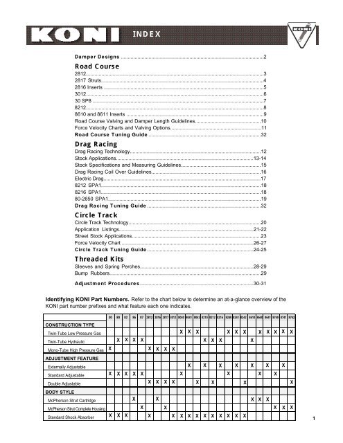
index
index
index

Create successful ePaper yourself
Turn your PDF publications into a flip-book with our unique Google optimized e-Paper software.
I N D E X<br />
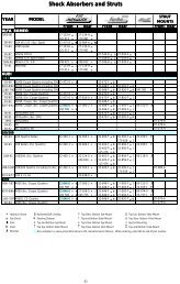
Damper Designs ......................................................................................................2<br />
Road Course<br />
2812..............................................................................................................................3<br />
2817 Struts....................................................................................................................4<br />
2816 Inserts ..................................................................................................................5<br />
3012..............................................................................................................................6<br />
30 SP8 ..........................................................................................................................7<br />
8212..............................................................................................................................8<br />
8610 and 8611 Inserts ..................................................................................................9<br />
Road Course Valving and Damper Length Guidelines...............................................10<br />
Force Velocity Charts and Valving Options.................................................................11<br />
Road Course Tuning Guide ................................................................................32<br />
Drag Racing<br />
Drag Racing Technology.............................................................................................12<br />
Stock Applications..................................................................................................13-14<br />
Stock Specifications and Measuring Guidelines.........................................................15<br />
Drag Racing Coil Over Guidelines..............................................................................16<br />
Electric Drag................................................................................................................17<br />
8212 SPA1..................................................................................................................18<br />
8216 SPA1..................................................................................................................18<br />
80-2650 SPA1.............................................................................................................19<br />
Drag Racing Tuning Guide .................................................................................32<br />
Circle Track<br />
Circle Track Technology..............................................................................................20<br />
Application Listings................................................................................................21-22<br />
Street Stock Applications............................................................................................23<br />
Force Velocity Chart ..............................................................................................26-27<br />
Circle Track Tuning Guide............................................................................24-25<br />
Threaded Kits<br />
Sleeves and Spring Perches.................................................................................28-29<br />
Bump Rubbers............................................................................................................29<br />
Adjustment Procedures.................................................................................30-31<br />
Identifying KONI Part Numbers. Refer to the chart below to determine an at-a-glance overview of the<br />
KONI part number prefixes and what feature each one indicates.<br />
30 80 82 86 87 2812 2816 2817 3012 8040 8041 8042 8210 8212 8216 8240 8241 8242 8610 8640 8641 8740 8741 8742<br />
CONSTRUCTION TYPE<br />
Twin-Tube Low Pressure Gas<br />
Twin-Tube Hydraulic<br />
Mono-Tube High Pressure Gas<br />
X<br />
X<br />
X<br />
X<br />
X<br />
X<br />
X<br />
X<br />
X<br />
X<br />
X X<br />
X X X X X X X X<br />
X X X<br />
X<br />
ADJUSTMENT FEATURE<br />
Externally Adjustable<br />
Standard Adjustable<br />
Double Adjustable<br />
X<br />
X<br />
X<br />
X<br />
X<br />
X<br />
X<br />
X<br />
X<br />
X<br />
X<br />
X<br />
X<br />
X<br />
X<br />
X<br />
X<br />
X<br />
X<br />
X<br />
X<br />
X<br />
X<br />
X<br />
BODY STYLE<br />
McPherson Strut Cartridge<br />
McPherson Strut Complete Housing<br />
Standard Shock Absorber<br />
X X X<br />
X<br />
X<br />
X<br />
X<br />
X<br />
X<br />
X<br />
X<br />
X X X X X X X<br />
X X X<br />
X X X<br />
1
DAMPER DESIGNS<br />
All hydraulic shock absorbers work by the principle of converting<br />
kinetic energy (movement) into thermal energy (heat).<br />
For that purpose, fluid in the shock absorber is forced to flow<br />
through restricted outlets and valve systems, thus generating<br />
hydraulic resistance.<br />
A telescopic shock absorber (damper) can be compressed and<br />
extended; the so called bump stroke and rebound stroke.<br />
Telescopic shock absorbers can be subdivided into:<br />
1. Twin-tube dampers, available in hydraulic and gas-hydraulic<br />
configuration.<br />
2. Mono-tube dampers, also called high pressure gas shocks.<br />
TWIN-TUBE SHOCK ABSORBERS (fig. A and B)<br />
The main components are:<br />
• outer tube, also called reservoir tube (6)<br />
• inner tube, also called cylinder (5)<br />
• piston (2) connected to a piston rod (1)<br />
• bottom valve, also called footvalve (7)<br />
• piston rod guide (3)<br />
How Does a Twin-Tube Shock Absorber Work?<br />
CHOOSING THE OPTIMUM DAMPER FOR YOUR VEHICLE<br />
Bump stroke.<br />
When the piston rod is pushed in, oil flows without resistance<br />
from below the piston through the outlets A, B, C, and D and the<br />
non-return valve (19) to the area above the piston. Simultaneously,a<br />
quantity of oil is displaced by the volume of the rod entering the<br />
cylinder. This volume of oil is forced to flow through the bottom<br />
valve into the reservoir tube filled with air (1 bar) or nitrogen gas<br />
(4-8 bar). The resistance, encountered by the oil on passing<br />
through the footvalve, generates the bump damping.<br />
Rebound stroke.<br />
When the piston rod is pulled out, the oil above the piston is<br />
pressurized and forced to flow through the piston. The resistance,<br />
encountered by the oil on passing through the piston, generates<br />
the rebound damping. Simultaneously, some oil flows<br />
back, without resistance, from the reservoir tube (6) through the<br />
footvalve to the lower part of the cylinder to compensate for the<br />
volume of the piston rod emerging from the cylinder.<br />
MONO-TUBE SHOCK ABSORBER (fig. C)<br />
The main components are:<br />
• (pressure) cylinder, also called housing<br />
• piston (2) connected to a piston rod (1)<br />
• floating piston, also called separating piston (15)<br />
• piston guide (3)<br />
How Does a Mono-Tube Shock Absorber Work?<br />
Bump stroke.<br />
Unlike the twin-tube damper, the mono-tube shock has no reservoir<br />
tube. There is still a need to store the oil that is displaced by<br />
the rod when entering the cylinder. This is achieved by making<br />
the oil capacity of the cylinder adaptable. Therefore the cylinder<br />
is not completely filled with oil; the lower part contains (nitrogen)<br />
gas under 20–30 bar. Gas and oil are separated by the floating<br />
piston (15).<br />
When the piston rod is pushed in, the floating piston is also<br />
forced down by the displacement of the piston rod, thus slightly<br />
increasing pressure in both gas and oil section. Also, the oil<br />
below the piston is forced to flow through the piston. The resistance<br />
encountered in this manner generates the bump damping.<br />
Rebound stroke.<br />
When the piston rod is pulled out, the oil between piston and<br />
guide is forced to flow through the piston. The resistance<br />
encountered in this manner generates the rebound damping. At<br />
the same time, part of the piston rod will emerge from th cylinder<br />
and the free (floating) piston will move upwards.<br />
2<br />
A B C<br />
TWIN TUBE TWIN TUBE MONO-TUBE HIGH<br />
HYDRAULIC LOW PRESSURE GAS PRESSURE GAS<br />
KONI Shock Absorber Components:<br />
1 Piston rod<br />
2 Piston<br />
3 Piston rod guide<br />
4 Piston rod seal<br />
5 Inner Cylinder<br />
6 Reservoir tube<br />
7 Foot valve<br />
8 Bypass valve<br />
9 Bypass spring<br />
10 Adjusting nut<br />
11 Adjusting knob<br />
12 Adjusting detent<br />
13 Compression valve assembly<br />
14 Rebound valve assembly<br />
15 Floating piston<br />
16 Dust cover<br />
17 Adjusting rod<br />
18 Dust cap<br />
19 Non return valve<br />
20 Non return valve<br />
21 Valves<br />
A, B, C, D, E, F, G, H, J, K and L<br />
Various orifices
28 Series<br />
ROAD COURSE<br />
The 28 Series are mono-tube dampers specifically designed for competition purposes,<br />
featuring externally adjustable compression and rebound. The precision<br />
adjustment mechanism allows for maximum control possible over the damping<br />
forces generated. In modern racing applications damper sensitivity, repeatability,<br />
and ease of use are a must. To achieve this, the 28 series uses a superior and<br />
advanced adjustment mechanism operated by closing or opening valve-loaded<br />
ports. By having all damping forces generated at the piston, the control over the<br />
damping forces is very precise. A separate reservoir is not needed to accommodate<br />
the bump adjuster. This makes for a compact and simple for installation.<br />
Series 2812<br />
The 2812 Series spans 35 different stroke/<br />
length combinations. In addition, 3 different top<br />
mounting eye lengths are available.<br />
For a damper to function properly, it must be<br />
the correct length and valving. Regardless of<br />
the actual mounting configuration, the basic<br />
method for selecting a damper is always the<br />
same. Please refer to page 10 for a guide<br />
through this process.<br />
TIP: Always select the longest L min you can<br />
accommodate. This ensures lowest friction plus<br />
the best durability.<br />
TYPE OF MOUNTING EYE<br />
#1 #2 #3<br />
Type Code L max L min L max L min L max L min Stroke L body<br />
214 214 185 219 190 224 195 29 139<br />
219 219 190 224 195 229 200 29 144<br />
224 224 190 229 195 234 200 34 144<br />
229 229 195 234 200 239 205 34 149<br />
234 234 195 239 200 244 205 39 149<br />
239 239 200 244 205 249 210 39 154<br />
244 244 200 249 205 254 210 44 154<br />
249 249 205 254 210 259 215 44 159<br />
254 254 205 259 210 264 215 49 159<br />
259 259 210 264 215 269 220 49 164<br />
264 264 210 269 215 274 220 54 164<br />
269 269 215 274 220 279 225 54 169<br />
274 274 215 279 220 284 225 59 169<br />
279 279 220 284 225 289 230 59 174<br />
284 284 220 289 225 294 230 64 174<br />
289 289 225 294 230 299 235 64 179<br />
294 294 225 299 230 304 235 69 179<br />
299 299 230 304 235 309 240 69 184<br />
304 304 230 309 235 314 240 74 184<br />
309 309 235 314 240 319 245 74 189<br />
314 314 235 319 240 324 245 79 189<br />
319 319 240 324 245 329 250 79 194<br />
324 324 240 329 245 334 250 84 194<br />
329 329 245 334 250 339 255 84 199<br />
334 334 245 339 250 344 255 89 199<br />
339 339 250 344 255 349 260 89 204<br />
344 344 250 349 255 354 260 94 204<br />
349 349 255 354 260 359 265 94 209<br />
354 354 255 359 260 364 265 99 209<br />
359 359 260 364 265 369 270 99 214<br />
364 364 260 369 265 374 270 104 214<br />
369 369 265 374 270 379 275 104 219<br />
374 374 265 379 270 384 275 109 219<br />
379 379 270 384 275 389 280 109 224<br />
384 384 270 389 275 394 280 114 224<br />
Series 2812LB<br />
For applications that require dampers with<br />
lengths greater than what is listed in the table<br />
above, the 2812 Long Body will soon be<br />
available. Please contact your KONI dealer<br />
for availability.<br />
3
ROAD COURSE<br />
4<br />
Series 2817<br />
The 2817 series is a semifinished strut<br />
d a m p e r. The strut housing and spring<br />
seats (for 2 1/2” I.D. springs) are made of<br />
hard-anodized aluminum. A r e m o v a b l e<br />
steel sleeve is fitted to the bottom part of<br />
the main cylinder of the strut housing to<br />
allow for fabrication of brackets to fit each<br />
particular application.<br />
The 2817 series uses a “twin guide” installation.<br />
The primary guide is fitted to the top of<br />
the main cylinder. The secondary guide is<br />
fitted to the lowest point of the damper body<br />
itself and runs up and down inside the strut<br />
housing. Therefore, when the strut is compressed,<br />
the distance between the guides<br />
increases. This reduces friction and increases<br />
strength dramatically under load.<br />
Damping adjustments for rebound and compression<br />
are made at the bottom of the strut unit.<br />
NOTE:<br />
* This is the max length allowed under dynamic conditions (see Disclaimer below).<br />
** The damper should only reach this length under static (no load) conditions.<br />
Disclaimer:<br />
Bracket Fabrication<br />
The 2817 is supplied with a steel sleeve of<br />
4.5mm wall thickness that can be removed<br />
to allow for welding on lower mounting<br />
brackets. The thickness of steel used to<br />
make these brackets should be approximately<br />
5mm. A TIG weld is recommended to<br />
minimize heat distortion of the sleeve.<br />
2817ATT-VVV-DD<br />
This is the generic part number for the 2817<br />
series. TT is the length code, VVV is the<br />
valving code, and DD is the length of the<br />
internal droop limiter.<br />
Droop Limiters<br />
A droop limiter can be installed to reduce L<br />
max. The limiter length can be increased in<br />
steps of 5mm and can be changed by a<br />
KONI service center. Please state the<br />
required length at the time of ordering.<br />
Length code L max Dynamic* L max Static** L min Stroke Max** L casing<br />
2817A43 VVV 00 429 429 310 119 251<br />
2817A47 VVV 00 469 469 330 139 271<br />
2817A51 VVV 00 509 509 350 159 291<br />
2817A55 VVV 25 524 549 370 179 311<br />
2817A59 VVV 25 564 589 390 199 331<br />
At full droop, the beam strength of a strut assembly is at its minimum. To warrant sufficient<br />
strength and safe operation, a droop limiter is usually installed inside the damper.<br />
Unfortunately, the resulting dimensions of the damper do not allow for the combination of a very<br />
low ride height and sufficient clearance to remove the wheels when the car is on jacks.<br />
As a solution, the droop limiter is shortened or removed. As a result, the damper can potentially<br />
be used outside of its safe operating limits.<br />
Under no circumstance should a dynamic load be allowed to act on the strut assembly when the<br />
dampers are at such extended droop.<br />
How to determine the required damper<br />
lengths for the 2817<br />
For the following paragraph, it is assumed<br />
that the car is already equipped with<br />
dampers.<br />
A. Put the car on a flat level surface.<br />
Measure the distance between the upper<br />
and lower spring seats.<br />
B. Jack the car up to maximum desired<br />
droop. Measure the distance between the<br />
upper and lower spring seats.<br />
C. Support the car on jack stands.<br />
Remove the wheels, springs, and bump<br />
rubbers. For convenience, disconnect the<br />
anti-roll bars if possible.<br />
D. Now raise the suspension, to the point<br />
where either the chassis would hit the<br />
ground, or a suspension component uses<br />
up all its available travel. If the factory<br />
length struts are being used, it is necessary<br />
to determine if the length of the strut<br />
housing will require shortening to achieve<br />
the desired bump travel.<br />
E . Subtracting the value found at D with the<br />
value found at B gives the required stroke.<br />
F. Find a 2817 that has this required<br />
stroke. Note its L min.<br />
G. Check that this L min fits within the<br />
dimension found at D.<br />
H. If the L min is too long, check the next<br />
shorter length and determine if the L max<br />
will be sufficient.<br />
I. If the L min is too short, check the next<br />
longer length. The L max can be shortened<br />
by increasing the length of the internal<br />
droop limiter of the damper.
ROAD COURSE<br />
Series 2816<br />
The 2816 is a damper for use in strut housings<br />
that are designed and fabricated by the<br />
customer. The damper is to be used in a<br />
“twin guide” installation. In this layout, the<br />
primary guide is located at the top of the<br />
suspension strut housing. The secondary<br />
guide is attached to the damper and moves<br />
up and down, relative to the primary guide.<br />
This configuration offers the stiffest assembly<br />
possible with lowest friction.<br />
Components Supplied by KONI<br />
– fully assembled piston rod attachment,<br />
containing the adjuster assembly.<br />
– primary guide bushing and the secondary<br />
guide PTFE ring.<br />
– lock nut with integrated dirt scraper.<br />
Strut Housing Fabrication<br />
All dimensional and finish requirements of<br />
the damper strut housing are noted in the<br />
drawing to the right. For the inside of the<br />
cylinder, it is important to achieve the small<br />
tolerance and smooth surface finish. Both<br />
are vital for low friction and durability.<br />
2816ATT-VVV-DD<br />
This is the generic part number for the 2816<br />
series. TT is the length code, VVV is the<br />
valving code, and DD is the length of the<br />
internal droop limiter.<br />
TIP: Always select the longest L min you<br />
can accommodate. This ensures the lowest<br />
friction plus the best durability.<br />
Droop Limiters<br />
A droop limiter can be installed to reduce L<br />
max. The limiter length can be increased in<br />
steps of 5mm and can be changed in a<br />
KONI service center. Please state the<br />
required length at the time of ordering.<br />
NOTE:<br />
* This is the max length allowed under dynamic<br />
conditions (see disclaimer on page 4).<br />
** The damper should only reach this length<br />
under static (no load) conditions.<br />
SPECIFICATIONS FOR STRUT HOUSING<br />
Length code L max L max L min Stroke L cylinder<br />
Dynamic* Static** Max**<br />
2816A43 VVV 00 429 429 310 119 251<br />
2816A47 VVV 00 469 469 330 139 271<br />
2816A51 VVV 00 509 509 350 159 291<br />
2816A55 VVV 25 524 549 370 179 311<br />
2816A59 VVV 25 564 589 390 199 331<br />
5
ROAD COURSE<br />
6<br />
Series 3012-1600<br />
The 3012 series features a threaded aluminum-body,<br />
external double-adjustability and<br />
a high pressure gas mono-tube design, ensuring<br />
optimum performance. Our patented<br />
mono-tube design allows for independent<br />
adjustments to the rebound and compression<br />
forces. All damping adjustments are made at<br />
the piston, eliminating the additional weight and<br />
packaging complications of an external reservoir.<br />
The 3012 series offers one of the broadest<br />
adjustment ranges in the industry, eliminating<br />
the need of constant revalving procedures<br />
from track to track<br />
Settings Available<br />
The 3012-1600 series dampers are available<br />
with a variety of valvings to meet your specific<br />
dampening requirements. Due to the unique<br />
valving and dampening characteristics available,<br />
we recommend that you discuss your<br />
needs with our technical staff prior to ordering.<br />
Listed below is a sample of valving codes, and<br />
the range of spring rates that are recommended.<br />
VALVING CODE<br />
B16<br />
B23<br />
SPRING RATES<br />
up to 250 lbs./in.<br />
250-1500 lbs./in.<br />
Styles Available<br />
B53 500-2000 lbs./in.<br />
The 3012 series dampers are available in<br />
B83 650-3500 lbs./in.<br />
either of two standardized styles. The part<br />
numbers ending in an even number are supplied<br />
with the standard eye, which has the<br />
rebound adjustment window on axis to the<br />
mounting eye. The dampers ending in an odd<br />
part number are supplied with the rebound<br />
adjustment window 90 degrees to the axis of<br />
the eye. Please note that the eye supplied with<br />
the odd numbered dampers increases the maximum<br />
and minimum dimension of the damper<br />
5mm (0.2”).<br />
Part Number Stroke Max L Min L A B Stroke Max L Min L A B<br />
3012-1600 55mm 264mm 209mm 165mm 75mm 2.16” 10.39” 8.23” 6.50” 2.95”<br />
-1601 269mm 214mm 10.59” 8.43”<br />
3012-1602 60mm 274mm 214mm 170mm 75mm 2.36” 10.79” 8.43” 6.69” 2.95”<br />
-1603 279mm 219mm 10.98” 8.62”<br />
3012-1604 65mm 284mm 219mm 175mm 75mm 2.56” 11.18” 8.62” 6.89” 2.95”<br />
-1605 289mm 224mm 11.38” 8.82”<br />
3012-1606 70mm 294mm 224mm 180mm 75mm 2.75” 11.57” 8.82” 7.10” 2.95”<br />
-1607 299mm 229mm 11.77” 9.02”<br />
3012-1608 75mm 304mm 229mm 185mm 75mm 2.95” 11.97” 9.02” 7.28” 2.95”<br />
-1609 309mm 234mm 12.17” 9.22”<br />
3012-1610 80mm 314mm 234mm 190mm 75mm 3.15” 12.36” 9.21” 7.48” 2.95”<br />
-1611 319mm 239mm 12.56” 9.41”<br />
3012-1612 85mm 324mm 239mm 195mm 100mm 3.35” 12.76” 9.41” 7.68” 3.94”<br />
-1613 329mm 244mm 12.96” 9.61”<br />
3012-1614 90mm 334mm 244mm 200mm 100mm 3.54” 13.15” 9.61” 7.87” 3.94”<br />
-1615 339mm 249mm 13.34” 9.80”<br />
3012-1616 95mm 344mm 249mm 205mm 100mm 3.74” 13.54” 9.80” 8.07” 3.94”<br />
-1617 349mm 254mm 13.74” 10.00”<br />
3012-1620 105mm 364mm 259mm 215mm 100mm 4.13” 14.33” 10.39” 8.46” 3.94”<br />
-1621 369mm 264mm 14.52” 10.39”<br />
3012-1622 110mm 374mm 264mm 220mm 100mm 4.33” 14.72” 10.39” 8.66” 3.94”<br />
-1623 379mm 269mm 14.92” 10.59”<br />
3012-1624 115mm 384mm 269mm 225mm 100mm 4.53” 15.12” 10.59” 8.86” 3.94”<br />
-1625 389mm 274mm 15.32” 10.79”<br />
3012-1626 120mm 394mm 274mm 230mm 100mm 4.72” 15.51” 10.79” 9.10” 3.94”<br />
-1627 399mm 279mm 15.70” 10.98”<br />
3012-1628 125mm 404mm 279mm 235mm 100mm 4.92” 15.92” 10.98” 9.25” 3.94”<br />
-1629 409mm 284mm 16.10” 11.18”<br />
3012-1630 130mm 414mm 284mm 240mm 100mm 5.12” 16.30” 11.18” 9.45” 3.94”<br />
-1631 419mm 289mm 16.50” 11.38”<br />
3012-1636 145mm 444mm 299mm 255mm 100mm 5.71” 17.48” 11.77” 10.04” 3.94”<br />
-1637 449mm 304mm 17.68” 11.97”<br />
3012-1646 160mm 494mm 334mm 286mm 100mm 6.30” 19.45” 13.15” 11.26” 3.94”<br />
-1647 499mm 339mm 19.65” 13.45”<br />
See page 10 to determine proper damper length.
ROAD COURSE<br />
Series 30 SP8<br />
The 30 SP8 Road Course shock features<br />
a threaded aluminum body, four-position<br />
rebound adjustability, and a high-pressure<br />
gas mono-tube design. The rebound<br />
forces can be adjusted 100%, while the<br />
compression forces are pre-set. T h i s<br />
rebuildable design offers a wide range of<br />
valving options to fit a variety of applications<br />
at an economical price.<br />
The 30 SP8 series dampers are available<br />
with a variety of valvings to meet<br />
your specific damping requirements.<br />
Due to the unique valving and damping<br />
characteristics available, we recommend<br />
that you discuss your needs with<br />
our technical staff prior to ordering.<br />
The steel spring seats that are included<br />
with the 30 SP8 series will accept<br />
springs with 2 1/4” I.D. or a 2 1/2” I.D.<br />
when used with a KONI adapter.<br />
Part Number Stroke Max L Min L A Stroke Max L Min L A<br />
30-0500 SP8 125mm 403mm 278mm 243mm 4.92” 15.87” 10.94” 9.57”<br />
30-0600 SP8 150mm 463mm 313mm 278mm 5.90” 18.23” 12.32” 10.94”<br />
30-0700 SP8 170mm 501mm 331mm 296mm 6.69” 19.72” 13.03” 11.65”<br />
30-0800 SP8 200mm 565mm 365mm 330mm 7.87” 22.24” 14.37” 12.99”<br />
30-0900 SP8 220mm 605mm 385mm 350mm 8.66” 23.81” 15.16” 13.78”<br />
See page 10 to determine proper damper length.<br />
7
ROAD COURSE<br />
Series 8212-1400<br />
The 8212 series is an aluminum-bodied<br />
externally-double adjustable coil over. It has<br />
a twin tube hydraulic construction that is fully<br />
rebuildable and the valving can be matched<br />
to a wide range of applications. Adjustment of<br />
the rebound and compression damping is<br />
provided by two controls and may be adjusted<br />
independently of one another, without<br />
removing it from the car.<br />
Settings Available<br />
The 8212-1400 series dampers are available<br />
in 7 standard valvings. Listed below are the<br />
valving codes, and the range of spring rates<br />
that are recommended.<br />
VALVING CODE SPRING RATES<br />
B1<br />
150-300 lbs./in.<br />
B2<br />
225-450 lbs./in.<br />
B3<br />
275-550 lbs./in.<br />
B6<br />
300-650 lbs./in.<br />
B7<br />
375-750 lbs./in.<br />
B8<br />
400-800 lbs./in.<br />
B8+ 600-2000 lbs./in<br />
Variations Available<br />
1 Settings for spring rates lighter than those of B1 or heavier than those listed for B8+ can<br />
be supplied after discussing your requirements with your KONI dealer.<br />
2 In its standard form, the 8212-1400 series accepts springs with an inside diameter of 2<br />
1/2”. If desired, 2 1/4” spring seats are available upon request.<br />
3 In applications where the minimum length of the damper is correct, but the desired droop<br />
travel is too long an internal rebound stop may be added to achieve the correct dimension.<br />
Discuss you needs with your KONI dealer.<br />
Part Number Stroke Max L Min L A Stroke Max L Min L A<br />
8212-1400 80mm 283mm 203mm 165mm 3.15” 11.14” 7.99” 6.50”<br />
8212-1402 85mm 93mm 208mm 170mm 3.35” 11.54” 8.19” 6.69”<br />
8212-1404 90mm 303mm 213mm 175mm 3.54” 11.93” 8.39” 6.89”<br />
8212-1406 95mm 313mm 218mm 180mm 3.74” 12.32” 8.58” 7.09”<br />
8212-1408 100mm 323mm 223mm 185mm 3.94” 12.72” 8.78” 7.28”<br />
8212-1410 105mm 333mm 228mm 190mm 4.13” 13.11” 8.98” 7.48”<br />
8212-1412 110mm 343mm 233mm 195mm 4.33” 13.50” 9.17” 7.68”<br />
8212-1414 115mm 353mm 238mm 200mm 4.53” 13.90” 9.37” 7.87”<br />
8212-1416 120mm 363mm 243mm 205mm 4.72” 14.29” 9.57” 8.07<br />
8212-1418 125mm 373mm 248mm 210mm 4.93” 14.69” 9.76” 8.27”<br />
8212-1420 130mm 383mm 253mm 215mm 5.12” 15.08” 9.96” 8.46”<br />
8212-1422 135mm 393mm 258mm 220mm 5.31” 15.47” 10.16” 8.66”<br />
8212-1424 140mm 403mm 263mm 225mm 5.52” 15.87” 10.35” 8.86”<br />
8212-1426 145mm 413mm 268mm 230mm 5.71” 16.26” 10.55” 9.06”<br />
8212-1428 150mm 423mm 273mm 235mm 5.90” 16.65” 10.75” 9.25”<br />
8212-1430 155mm 433mm 278mm 240mm 6.10” 17.05” 10.95” 9.45”<br />
See page 10 to determine proper damper length.<br />
Series 8211<br />
The 8211 series is a nickel-plated steel body version of the 8212, offering identical performance<br />
with a slight sacrifice in weight. This is an ideal shock for vintage applications that<br />
require a steel body shock.<br />
8
ROAD COURSE<br />
8611 Series Double Adjustable Strut Inserts<br />
The 8611 series double adjustable strut insert is one of<br />
the new additions to the KONI road race offerings.<br />
Originally designed for European touring car classes utilizing<br />
strut suspensions, the 8611 has become an affordable<br />
double adjustable option for club racers and<br />
autocrossers in North America.<br />
The KONI 8611 series is a twin-tube hydraulic that is<br />
externally adjustable in both rebound and compression<br />
damping. The compression adjuster is located in bottom<br />
end of the strut cartridge and requires a 1/2” diameter<br />
hole to be made in the bottom of the strut housing for<br />
access to the adjuster.<br />
To determine the correct 8611 for your application, follow<br />
these steps:<br />
1. Measure the inside depth of your strut housing.<br />
(NOTE: At this time also make certain that the inside<br />
diameter of your housing is large enough to accept<br />
the KONI insert.)<br />
2. For the KONI insert to be installed properly the<br />
measured depth of your strut housing must be 1-<br />
4mm (.04” - .16”) shorter than the dimension “A” in<br />
the chart below.<br />
3. In the event that the KONI “A” length is shorter than<br />
the required, the user must then fabricate a spacer<br />
and place it under the KONI insert so as to achieve<br />
the proper depth relationship.<br />
4. After the KONI insert with the correct “A” length has<br />
been determined, verify that the stroke length will be<br />
appropriate for your application.<br />
The 8611 series is not supplied with a threaded locknut<br />
to retain the insert into the strut housing. If new locknuts<br />
are required for you application, please refer to the chart<br />
below to determine which part number you need when<br />
placing your order.<br />
Part Number Stroke Max L Min L A D Stroke Max L Min L A D<br />
8611-1256 Sport 140mm 520mm 380mm 307mm 45.5mm 5.51” 20.47” 14.96” 12.09” 1.79”<br />
8611-1257 Sport 143mm 500mm 357mm 290mm 45.0mm 5.63” 19.69” 14.06” 11.42” 1.77”<br />
8611-1258 Sport 158mm 615mm 457mm 389mm 45.0mm 6.22” 24.21” 17.99” 15.32” 1.77”<br />
8610 Series Externally Adjustable Strut Insert<br />
The 8610-1149 McPherson strut cartridge<br />
insert fits a variety of road racing and<br />
autocross cars.<br />
The KONI 8610-1149 offers externally<br />
adjustable rebound damping with unique<br />
valving characteristics that have been<br />
developed in conjunction with many top racing<br />
teams and chassis builders. The piston<br />
rod is designed to fit through a 5/8" bearing/camber<br />
plate assembly.<br />
To determine the correct fitting of an 8610-<br />
1149, please follow these guidelines:<br />
1 Measure the inside depth of your existing<br />
strut housing. Also make certain that<br />
the inside diameter of your housing is<br />
large enough to accept the KONI insert,<br />
which has an O.D. of 43.5mm (1.71").<br />
2 For the KONI 8610-1149 to be installed<br />
p r o p e r l y, the inside depth of your housing<br />
must be 326-329mm (12.83" - 12.95").<br />
3 In the event that your existing strut housing<br />
depth is greater than the above recommended<br />
depth, a spacer must be fabricated<br />
and placed under the KONI insert<br />
to provide the proper depth relationship.<br />
Variations Available<br />
The 8610-1149 is supplied with a threaded<br />
locknut of M48x1.5 (Thread and Pitch) to hold<br />
the insert into the strut housing. However, if you<br />
require a different size locknut please specify<br />
which of the following part numbers you need<br />
when placing your order:<br />
THREAD & PITCH<br />
PART NO.<br />
M48 x 1.50 70.25.00.078.0<br />
(supplied locknut)<br />
M45 x 1.25 70.25.00.092.0<br />
M48 x 1.00 70.25.00.077.0<br />
M51 x 1.25 70.25.00.091.0<br />
M51 x 1.50 70.25.00.076.0<br />
M52 x 1.50 70.25.00.067.0<br />
52.8WW 70.25.00.087.0<br />
Part Number Stroke Max L Min L A D Stroke Max L Min L A D<br />
8610-1149 151mm 550mm 451mm 330mm 43.5mm 5.94” 21.66” 15.71” 12.99” 1.71”<br />
9
ROAD COURSE<br />
DETERMINING ROAD COURSE VA LV I N G<br />
In the Force vs. Velocity graph on page 11, the<br />
standard valvings for KONI road course dampers<br />
are listed. Only the minimum and maximum<br />
adjustment curves are shown. If you need assistance<br />
in selecting a valving for your application,<br />
please have the following information available<br />
when you contact your KONI dealer:<br />
• Spring rates<br />
• Motion ratios<br />
Motion ratio is the term used to indicate the ratio<br />
between wheel movement and damper movement.<br />
This ratio is an important factor when the required<br />
valving is selected, because it determines the piston<br />
velocities the damper will “see”.<br />
Motion ratio = Damper movement/Wheel movement<br />
This ratio is easily measured: assuming the car is<br />
without wheels, springs, and anti-roll bars:<br />
1. Lower the suspension to its maximum droop<br />
position.<br />
2. Measure the distance between the damper<br />
mounting points.<br />
3. Raise the suspension to the minimum ride<br />
height position as found earlier and repeat step 2.<br />
4. The mean motion ratio can now be calculated<br />
using the formula stated above.<br />
HOW TO DETERMINE THE REQUIRED DAMPER LENGTHS<br />
Double eye mounting style: 2812, 3011, 3012,<br />
30 SP8, 8212<br />
A . Prepare the car for making measurements:<br />
put it on a flat and level surface, support it on<br />
jack stands as such to lift the wheels off the<br />
ground. Remove the wheels, springs and<br />
dampers. Disconnect the anti-roll bars if fitted.<br />
B. Check if the upper and lower mounting eyes<br />
of the damper you have selected will clear the<br />
attachment points on the car under all normal<br />
operating motions.<br />
C. 1. The suspension should now be set at its<br />
maximum droop position. Take careful note<br />
of which suspension component is limiting<br />
the suspension from traveling any further.<br />
2. Lift the suspension just enough to prevent<br />
that component from binding.<br />
3. Measure the center to center distance<br />
between the upper and lower damper<br />
attachment points. This is the open length<br />
or Lmax.<br />
4. Refer to the chart that corresponds with the<br />
damper that you have selected. Find the<br />
Lmax that matches the one you measured.<br />
If no exact match can be found, decrease<br />
Lmax to the next available length.<br />
NOTE: All KONI dampers are designed to<br />
withstand the loads of limiting suspension<br />
droop and it is advisable to make use of this<br />
feature.<br />
D. 1. Raise the suspension to the point where<br />
the chassis would hit the ground, or a suspension<br />
component uses up all of its available<br />
travel.<br />
2. Now again measure the distance between<br />
the damper mounting points.<br />
3. Check that this figure is greater that the<br />
Lmin found at point D1.<br />
4. If this is not the case, decide if you need all<br />
the available droop-travel. If not, decrease<br />
Lmax to the next available fit an go back to<br />
step C4.<br />
10
ROAD COURSE<br />
FORCE VELOCITY SPECIFICAT I O N S<br />
28 SERIES<br />
FORCE VS.<br />
VELOCITY GRAPH<br />
Available standard valvings:<br />
only the minimum and maximum<br />
adjustments are shown.<br />
3011/3012<br />
Valving code<br />
Test Velocity<br />
Compression<br />
Rebound<br />
(in/sec)<br />
Force (lbs)<br />
Force (lbs)<br />
Min/Max<br />
Min/Max<br />
BA16 8.67” 38 / 227 84 / 632<br />
BA23 8.67” 55 / 375 132 / 992<br />
BA53 8.67” 55 / 375 243 / 1279<br />
BA83 8.67” 88 / 529 397 / 2050<br />
8211/8212<br />
Valving code<br />
Test Velocity<br />
Compression<br />
Rebound<br />
(in/sec)<br />
Force (lbs)<br />
Force (lbs)<br />
Min/Max<br />
Min/Max<br />
B1 13.00” 44 / 220 176 /430<br />
B2 13.00” 88 / 375 243 / 606<br />
B3 13.00” 88 / 375 298 / 760<br />
B6 13.00” 88 / 375 320 / 816<br />
B7 13.00” 88 / 375 408 / 970<br />
B8 13.00” 88 / 375 430 / 1036<br />
B8+ 13.00” 88 / 375 705 / 1620<br />
Road Course Inserts<br />
Valving code<br />
Test Velocity<br />
Compression<br />
Rebound<br />
(in/sec)<br />
Force (lbs)<br />
Force (lbs)<br />
Min/Max<br />
Min/Max<br />
8610-1149 13.00” 187 187 / 425<br />
8611-1256 Sport 13.00” 176 / 485 276 / 705<br />
8611-1257 Sport 13.00” 143 / 463 243 / 507<br />
8611-1258 Sport 13.00” 143 / 463 243 / 507<br />
11
DRAG RACING TECHNOLOGY<br />
KONI ADJUSTABLE DRAG RACING<br />
SHOCK ABSORBERS SERIES SPA 1<br />
90/10 THEORY FALLS BY WAYSIDE<br />
The KONI SPA1 series shock absorber (for drag racing only) is a<br />
complete departure from the old “90/10” thinking which is no<br />
longer effective in modern drag race competition.<br />
The old thinking was to allow the vehicle front end to rise quickly<br />
and stay there to promote as much weight transfer as possible to<br />
the rear wheels. This was achieved by virtually no rebound forces<br />
(“10”) and a great deal of bump forces (“90”). This massive<br />
amount of bump force was supposed to hold the front suspension<br />
up to maintain that “bite.”<br />
Unfortunately the nose-in-the-air position trapped huge volumes<br />
of air which ruined any attempt at aerodynamics so E.T.s were not<br />
as good as they could have been.<br />
KONI SPA1 series shocks deal with this in several ways. First,<br />
they use virtually no bump (compression) damping. Why? To<br />
allow the front-end to settle quicker, restoring the nose down attitude<br />
that is so essential for cleaner air flow. Second, the rebound<br />
(extension) forces are velocity sensitive; that is, they increase at a<br />
rate directly proportionate to piston speed.<br />
So, what does this mean?<br />
On a dry surface with good hookup, the amount of lift generated<br />
by initial launch is, of course, very sudden and quite violent. The<br />
velocity sensitive nature of the SPA1 reacts instantly (no magic,<br />
just good design and tuning) to damp this lift to avoid bogging<br />
caused by too much weight transfer. (Yes, you can have too much<br />
of a good thing.)<br />
On the other end of the spectrum, a slick surface would naturally<br />
provide less lift and tire shock, so the SPA1 then allows more<br />
movement of the front end because the lack of traction initially<br />
does not lift the chassis as violently. This “gentle” impulse does<br />
not activate the higher speed circuit of the SPA1, so you end up<br />
with more front to rear weight transfer and accordingly better bite.<br />
Not only that, they have five settings that enable you to tune your<br />
chassis. For KONI rear SPA1 shocks, there is a big difference.<br />
They still have nearly zero bump (compression) damping but the<br />
rebound damping, unlike the fronts, is digressive.<br />
Digressive?<br />
Yes. This means they are designed to digress, or “blow off” at<br />
high piston speed. Why? Well, if you had the velocity sensitive<br />
type setting the front shocks use, it would be possible to grossly<br />
over damp the rear suspension on initial launch, thereby picking<br />
up rear wheels. The rear SPA1 KONI will “blow off” then, and<br />
allow proper “unwinding” of the rear suspension.<br />
WARNING<br />
KONI Series SPA1 shock absorbers are specifically for<br />
use in off highway drag race competition only. If used on<br />
public highways loss of vehicle control and consequent<br />
personal injuries may result.<br />
12
DRAG RACING<br />
STOCK APPLICAT I O N S<br />
Make / Model Year Front Rear<br />
BUICK<br />
Apollo, Skylark 74-79 80-1958 SPA1 80-1661 SPA1<br />
Centurion, Electra, LeSabre 71-76 80-1958 SPA1 Not Available<br />
Century Wagon 73-77 80-1958 SPA1 Not Available<br />
Century, Regal (Exc. Wagons) 70-87 80-1958 SPA1 80-1661 SPA1<br />
Regal, Grand National 78-87 80-1958 SPA1 80-1661 SPA1<br />
Electra, LeSabre (Exc. FWD) 77-85 80-1958 SPA1 80-1661 SPA1<br />
Skyhawk 75-80 80-2329 SPA1 Revalve 80-2321<br />
Skylark, Special 68-72 80-1958 SPA1 80-1661 SPA1<br />
Skylark, Special 64-67 80-1660 SPA1 80-1661 SPA1<br />
Sportwagon 70-72 80-1958 SPA1 80-1661 SPA1<br />
CHEVROLET<br />
Camaro 93-99 8210-1161 SPA1 80-2501 SPA1<br />
Camaro incl. Z-28 82-92 8710-1289 SPA1 80-2501 SPA1<br />
Camaro incl. Z-28 70-81 80-2108 SPA1 80-2109 SPA1<br />
Camaro W/Mono-Leaf Spring 68-69 80-1914 SPA1 80-1915 SPA1<br />
Camaro W/Multi-Leaf Spring 68-69 80-1914 SPA1 80-1953 SPA1<br />
Camaro 67 80-1914 SPA1 80-1915 SPA1<br />
Caprice, Impala Sedans, Wagons 77-95 80-1958 SPA1 80-1661 SPA1<br />
Caprice, Impala Sedans, Wagons 66-78 80-1958 SPA1 Not Available<br />
Chevelle, Malibu Sedans 68-85 80-1958 SPA1 80-1661 SPA1<br />
Chevelle, Malibu SS-396 66-67 80-1660 SPA1 80-1661 SPA1<br />
Chevelle, Malibu Sedans 64-67 80-1660 SPA1 80-1661 SPA1<br />
Chevy 55-57 80-2108 SPA1 Not Available<br />
Nova 75-79 80-1958 SPA1 80-1661 SPA1<br />
Chevy II, Nova 68-74 80-1958 SPA1 80-1661 SPA1<br />
Chevy II, Nova 62-67 80-1546 SPA1 80-1915 SPA1<br />
Corvette 63-83 80-1820 SPA1 80-1576 SPA1<br />
El Camino 68-77 80-1958 SPA1 Not Available<br />
Monte Carlo 70-87 80-1958 SPA1 80-1661 SPA1<br />
Monza, Vega 72-80 80-2329 SPA1 Revalve 80-2321<br />
DODGE<br />
Challenger 70-74 80-1538 SPA1 Revalve 82-1255<br />
Charger 77-81 80-2660 SPA1 Not Available<br />
Charger, Coronet 73-76 80-2660 SPA1 Revalve 82-1255<br />
Charger, Coronet 65-72 80-1538 SPA1 Revalve 82-1255<br />
Dart, Demon, GTS 63-76 80-1423 SPA1 80-1539 SPA1<br />
FORD<br />
Mustang (Exc. IRS) 94-99 8710-1311 SPA1 80-2401 SPA1 or<br />
— double adjustable rear alternative — 8042-1134 Sport<br />
— Quad Shock — 25-1215<br />
Mustang, 8 cyl. 87-93 8710-1272 SPA1 80-2401 SPA1 or<br />
— double adjustable rear alternative — 8042-1026 Sport<br />
— Quad Shock — 25-1215<br />
Mustang, 4 cyl. only 86-92 Revalve 8741-1103 80-2401 SPA1<br />
— Quad Shock — 25-1215<br />
Mustang w/1-1/2 in. Lower 79-86 Revalve 8741-1103 80-2401 SPA1<br />
Rear Bushing (Exc. SVO)<br />
— Quad Shock — 25-1215<br />
Mustang 74-78 80-2660 SPA1 Revalve 80-2288<br />
Mustang 71-73 Revalve 82-1742 80-2511 SPA1<br />
Mustang 64-70 80-2510 SPA1 80-2511 SPA1<br />
Pinto Sedan & Wagon 70-80 80-2660 SPA1 Not Available<br />
13
DRAG RACING<br />
STOCK APPLICAT I O N S<br />
Make / Model Year Front Rear<br />
MERCURY<br />
Capri w/1-1/2 (in.) Lower Rear Bushing 79-86 Revalve 8741-1103 80-2401 SPA1<br />
— Quad Shock — 25-1215<br />
Cougar 67-70 80-2510 SPA1 Not Available<br />
OLDSMOBILE<br />
Cutlass Sedan 68-87 80-1958 SPA1 80-1661 SPA1<br />
Cutlass Vista Cruiser 73-77 80-1958 SPA1 Not Available<br />
Cutlass 442 66-67 80-1660 SPA1 80-1661 SPA1<br />
Cutlass F-85 (Exc. 442) 64-67 80-1660 SPA1 80-1661 SPA1<br />
Omega 75-79 80-1958 SPA1 80-1661 SPA1<br />
Starfire 75-80 80-2329 SPA1 Revalve 80-2321<br />
PLYMOUTH<br />
Barracuda 70-74 80-1538 SPA1 Revalve 82-1255<br />
Barracuda 64-69 80-1423 SPA1 80-1539 SPA1<br />
Belvedere,Satellite 73-74 80-2660 SPA1 Not Available<br />
Duster/Valiant 63-76 80-1423 SPA1 80-1539 SPA1<br />
Road Runner 73-75 80-2660 SPA1 Revalve 82-1255<br />
Road Runner 68-72 80-1538 SPA1 Revalve 82-1255<br />
PONTIAC<br />
Astre 75-77 80-2329 SPA1 Revalve 80-2321<br />
Bonneville, Catalina, Parisienne, 77-81 80-1958 SPA1 80-1661 SPA1<br />
Sedans & Wagons<br />
Bonneville, Catalina, Parisienne, 65-76 80-1958 SPA1 Not Available<br />
Sedans & Wagons<br />
Can-Am 77 80-1958 SPA1 80-1661 SPA1<br />
Firebird Incl. Trans-Am 93-99 8210-1161 SPA1 80-2501 SPA1<br />
Firebird Incl. Trans-Am 82-92 8710-1289 SPA1 80-2501 SPA1<br />
Firebird Incl. Trans-Am 70-81 80-2108 SPA1 80-2109 SPA1<br />
Firebird 69 80-1914 SPA1 Not Available<br />
Firebird 68 80-1914 SPA1 80-1953 SPA1<br />
Firebird 67 80-1914 SPA1 80-1915 SPA1<br />
Grand Am 73-77 80-1958 SPA1 80-1661 SPA1<br />
Grand Prix 69-87 80-1958 SPA1 80-1661 SPA1<br />
GTO, Lemans, Tempest Sedans 68-77 80-1958 SPA1 80-1661 SPA1<br />
GTO, Lemans, Tempest Sedans 64-67 80-1660 SPA1 80-1661 SPA1<br />
Lemans Wagon 73-77 80-1958 SPA1 Not Available<br />
Parisienne Incl. Wagon 83-86 80-1958 SPA1 80-1661 SPA1<br />
Phoenix, Ventura II 75-79 80-1958 SPA1 80-1661 SPA1<br />
Sunbird 76-80 80-2329 SPA1 Revalve 80-2321<br />
Ventura 72-74 80-1958 SPA1 80-1661 SPA1<br />
Note: The KONI Service Center (refer to page 33) is available to modify valving due to individual vehicle modifications or driver needs.<br />
14
DRAG RACING<br />
STOCK SPECIFICAT I O N S<br />
FRONT MOUNTING STYLE Max. Min. REAR MOUNTING STYLE Max. Min.<br />
Part Number Top Bottom Length Length Part Number Top Bottom Length Length<br />
80-2660 SPA1 Pin Eye 11.69” 8.00” 80-1576 SPA1 Eye Eye 14.13” 10.12”<br />
80-2329 SPA1 Pin Fork 12.32” 8.32” 80-2511 SPA1 Pin Pin 16.46” 10.12”<br />
80-1914 SPA1 Pin Fork 13.27” 8.62” 80-1953 SPA1 Pin 1-Stud 19.06” 11.65”<br />
80-1958 SPA1 Pin Fork 13.66” 8.82” 80-1915 SPA1 Pin Eye 19.80” 12.01”<br />
80-1820 SPA1 Pin Fork 13.66” 8.82” 80-2501 SPA1 Pin Stud 20.12” 12.20”<br />
80-2510 SPA1 Fork 2-Stud 14.40” 9.37” 80-2401 SPA1 Pin Eye 20.35” 12.32”<br />
80-1660 SPA1 Pin Fork 14.80” 9.37” 80-2109 SPA1 Fork Pin 20.47” 12.48”<br />
80-2108 SPA1 Pin Fork 14.84” 9.41” 80-1661 SPA1 Fork 1-Stud 21.18” 12.99”<br />
80-1423 SPA1 Pin Eye 14.88” 9.50” 80-1539 SPA1 Eye Eye 21.89” 13.50”<br />
80-1538 SPA1 Pin Eye 15.83” 10.00”<br />
80-1546 SPA1 Pin 2-Stud 16.30” 10.00”<br />
HOW TO MEASURE MAXIMUM/MINIMUM LENGTHS<br />
Refer to next page or compare your existing shock as follows:<br />
1 Maximum length - fully extend the shock absorber and<br />
measure from center of eye(s), including single stud or fork<br />
mounts; or in the case of pin or 2-stud mounts, from the<br />
start of the pin or 2-stud mount as it emerges from the<br />
shock body.<br />
2 Minimum length - completely compress shock absorber and<br />
measure.<br />
Single stud and fork configurations may be pressed out to<br />
allow for an eye style mounting.<br />
15
DRAG RACING<br />
COIL OVER GUIDELINES<br />
The KONI universal drag racing coil over shocks have long been the mainstay on the professional circuit.<br />
These shocks are available in single and double adjustment configuration.<br />
HOW TO DETERMINE THE CORRECT SHOCK ABSORBER LENGTH<br />
Please observe the following guidelines when determining the<br />
correct shock absorber length for your vehicle.<br />
1 Preparing the car.<br />
Place the car on a level surface and remove springs, shock<br />
absorbers, bump rubbers and sway bar(s).<br />
2 Determining the Maximum Length.<br />
• Raise the car body until the tires are lifted off the ground.<br />
Take careful note of which component of the suspension is<br />
limiting the suspension from traveling further.<br />
• Raise the tire enough to prevent that suspension component<br />
from binding.<br />
• Measure between the center of the upper and lower shock<br />
mounting points. This gives you the desired maximum<br />
length shock.<br />
All KONI shocks are designed to withstand the loads of<br />
limiting the suspension droop travel and it is advisable to<br />
take advantage of this feature.<br />
3 Determining the Minimum Length.<br />
• Lower the car to the point at which the tub just touches on<br />
the pavement, or a tire just touches on the inside of the<br />
fender well, or some other suspension component uses up<br />
all its available travel.<br />
• Measure between the center of the upper and lower shock<br />
mounting points. Now select a KONI shock with a minimum<br />
which is shorter than your measured minimum suspension<br />
length. By choosing a slightly shorter shock you protect<br />
the shock from bottoming out and causing internal damage.<br />
HOW TO DETERMINE SPRING REQUIREMENTS-GENERAL GUIDELINES*<br />
1 Determining Travel.<br />
It is recommended that there be approximately 3” of compression<br />
travel available (including the bump stop). This<br />
means the chassis must be supported by a spring rate that<br />
will allow the chassis to be supported 3” upward from the<br />
bottoming position.<br />
2 Determining the Vehicle Sprung Weight.<br />
• Establish front and rear weight of the vehicle.<br />
• Establish unsprung weight. This is the weight not supported<br />
by the springs, i.e., tires, wheels, wheelie bars,<br />
brakes, and 1/2 the weight of the shock, spring, driveline<br />
and ladder bar or four link. 1/2 the weight is used for<br />
some components because their weights are equally<br />
shared between sprung and unsprung weight.<br />
• Determine Sprung Weight - The weight of the vehicle less<br />
the unsprung weight.<br />
3 Spring Rate.<br />
Divide the rear sprung weight by 2 to determine the load for<br />
each rear corner. Divide the front sprung weight by 2 to<br />
determine the load for each front corner. If the load for the<br />
rear corners is 330 lbs. each (660 lbs./2=330 lbs.) then<br />
divide the 330 lbs. by the compression travel needed and<br />
you arrive at the base spring rate of 110 lbs. per inch.<br />
330 lbs./3” compression travel = 110 lbs. spring rate.<br />
This does not take into account a lever ratio that may be<br />
applied to the spring rate.<br />
4 How to run a lighter spring rate.<br />
Because KONI coil over shocks feature an adjustable<br />
spring platform it is possible to run a lighter spring rate by<br />
preloading the spring. For example, with 3” of travel a 95<br />
lb. spring will be 45 lbs. softer than a 110 lb. spring.<br />
110 lbs. - 95 lbs. = 15 lbs.<br />
15 lbs. x 3 = 45 lbs.<br />
To regain 45 lbs. simply preload the 95 lb. spring by screwing<br />
up on the bottom adjustable spring platform by 1/2”.<br />
1/2 of 95 = 47.5 lbs.<br />
You are now able to support the chassis at the desired ride<br />
height but with a softer spring rate, thus allowing more<br />
weight transfer to the rear and a better bite.<br />
To preload a spring properly, the difference between<br />
free height and compressed height (coil bind position)<br />
must be determined and coordinated with the amount<br />
of usable shock travel. The spring minimum or coil<br />
bind position must not be greater than the amount of<br />
shock travel desired.<br />
16
DRAG RACING COIL OVERS<br />
Electric Drag<br />
The 12 Series electric dampers offer the ultimate in adjustable drag race<br />
suspension. Rebound damping forces are adjusted by an electric servo<br />
motor located inside the piston rod. This allows the driver to launch the car<br />
with a high rebound force setting, then change to a softer setting by a remote<br />
switch to optimize traction. The SPA11 offers higher rebound forces for applications<br />
using higher rate springs. The spring seats accept a 2 1/4” I.D. spring<br />
or a 2 1/2” I.D. when used with the nylon adapters. These kits come complete<br />
with wiring harness and control box.<br />
Part Number Stroke Max L Min L<br />
12-2021 6.57” 19.25” 12.68”<br />
12-2021 SPA11 6.57” 19.25” 12.68”<br />
Bump Rubber = 1"<br />
The damping forces of the different adjustment rebound settings are identified at 1, 2, 3 and 4.<br />
Additionally there are 12 independent manual bump (compression) adjustments available.<br />
17
DRAG RACING COIL OVERS<br />
KONI COIL OVER DRAG RACING DAMPERS<br />
8212 SPA1<br />
The 8212 SPA1 features externally adjustable rebound and compression<br />
damping. Due to its unique valving and wide range of adjustment, this drag<br />
racing damper satisfies a wide range of suspension configurations. the 8212<br />
SPA1 is fully rebuildable and comes complete with 2 1/2” I.D. spring hardware<br />
and 1/2” I.D. spherical bearings.<br />
Part Number Stroke Max L Min L<br />
8212-1121 SPA1 513” 15.88” 10.75”<br />
8212-1126 SPA1 6.00” 17.50” 11.50”<br />
8212-1123 SPA1 7.00” 19.50” 12.50”<br />
Bump Rubber = 2-3/16"<br />
8216 SPA1<br />
The 8216 SPA1 is an aluminum bodied coil over that is designed for use with<br />
2 1/2” I.D. springs. These single adjustable drag race dampers are externally<br />
adjustable on rebound with a fixed compression setting.<br />
Part Number Stroke Max L Min L<br />
8216-2027 2.52” 11.26” 8.74”<br />
8216-1906 SPA1 4.61” 15.59” 10.98”<br />
8216-1907 SPA1 5.44” 17.17” 11.73”<br />
8216-1908 SPA1 6.37” 19.13” 12.76”<br />
Bump Rubber = 2-5/32" (1-9/16" for 8216-2127)<br />
18
DRAG RACING COIL OVERS<br />
KONI COIL OVER DRAG RACING DAMPERS<br />
80-2650 SPA1<br />
The 80-2650 SPA1 is an economical steel bodied coil over that is designed<br />
for use with 2 1/2” I.D. springs. These single adjustable dampers are internally<br />
adjustable on rebound with a fixed compression setting. The 80-2650<br />
SPA1 mounting has 1/2” I.D. rubber mounting bushings.<br />
Part Number Stroke Max L Min L<br />
80-2650 SPA1 5.08” 15.71” 10.63”<br />
Bump Rubber = 15/32"<br />
KONI REPLACEMENT COMPONENTS<br />
BEARINGS<br />
1425.50.00.13 1” O.D. 1/2” I.D.<br />
1038.50.02.54 1” O.D. snap ring<br />
BUMP RUBBERS<br />
70.34.53.000.0 2-5/32” Length<br />
70.34.54.000.0 1-9/16” Length<br />
ELECTRIC DRAG<br />
70.29.01.228.0 Upper spring seat<br />
71.29.11.048.0 Lower spring seat<br />
71.29.13.008.0 Locking ring<br />
15.29.04.003.0 Nylon 2.25” to 2.5” spring seat adaptor<br />
70.80.40.048.0 Electric Box<br />
71.80.10.034.0 Wiring Harness<br />
8212<br />
70.29.01.121.0 Upper spring seat<br />
8212.29.129 Lower spring seat<br />
8212.29.011 Locking ring<br />
15.29.04.003.0 Nylon 2.25” to 2.5” spring seat adaptor<br />
8216<br />
70.29.01.119.0 Upper spring seat<br />
70.29.11.129.0 Lower spring seat<br />
71.29.13.011.0 Locking ring<br />
80-2650<br />
70.29.01.230.0 Upper spring seat<br />
70.29.11.246.0 Lower spring seat<br />
70.29.13.002.0 Locking ring<br />
70.52.21.134.0 Rubber bushing<br />
19
KONI’S SUPERIOR SHOCK<br />
CIRCLE TRACK<br />
T E C H N O L O G Y<br />
KONI’s Mono-Tube, High Pressure Gas Design Damping Solution<br />
To meet the demands of Oval Track racing KONI has chosen the Mono-tube, high pressure<br />
gas design, which provides no fade valving and enables mounting of the shock absorber<br />
upside-down, lowering the unsprung weight of the vehicle.<br />
KONI’s Mono-Tube Design vs. Gas Cell Design<br />
Some other manufacturers place a plastic bag filled with gas inside a hydraulic twin tube shock<br />
absorber, as a means of preventing aeration or free stroke, when the shock absorber is mounted<br />
upside-down. In theory this is logical thinking; however, in practice: the plastic bags usually<br />
fail, resulting in aeration and reduced performance.<br />
The plastic bags are not heat resistant and float within the shock absorber. The bags fail<br />
prematurely because of the abrasions received as it floats within the cylinder, and the<br />
high operating temperatures experienced in oval track racing.<br />
When mounting a shock absorber upside-down, the only shock absorber design that will<br />
not fail under the extreme conditions of oval track racing is the Mono-tube design.<br />
Lacking the engineering and manufacturing sophistications of KONI, other suppliers offer the<br />
“gas cell” or plastic bag design.<br />
Other manufacturers’“gas cell” bag. These bags fail<br />
prematurely, causing shock fade.<br />
1 Adjustment Button. 4 Position Adjustable - KONI’s patented adjustment<br />
design enables 1 KONI shock to have 4 distinct and separate rebound valvings,<br />
by a simple push of a button. This feature allows for tuning of the chassis.<br />
2 Guide & Seal. Low friction Viton seal ensures continued peak performance;<br />
other gas cell shock designs have been measured at 3 times the friction value<br />
of KONI. The KONI guide is made of hardened steel and includes a sintered<br />
bushing for long life; other gas cell designs are not hardened, nor include a<br />
bushing.<br />
3 Piston Rod. Highest tensile strength of any make. KONI rod will withstand<br />
850 lbs. of force prior to bending 1% - other competitive rods bend between<br />
625 and 725 lbs. of force. Super Chrome finished and lapped (over 3 times<br />
smoother than gas cell design) for continued peak performance and superior<br />
seal life.<br />
4 Piston & Teflon Band. Large piston diameter (1.81” vs. gas cell design of<br />
1.38”) provides velocity-sensitive valving. The valves on the piston monitor<br />
the oil flow and damping forces. The Teflon Band provides low friction value<br />
- other gas cell designs contain lower grade rubber O-rings, which damage<br />
quickly.<br />
5 Cylinder Wall. Precision drawn seamless tubing (other gas cell designs<br />
have abrasive seam welds) ensures low friction value .080” thick cylinder wall<br />
withstands tract abuse.<br />
6 Damping Fluid. Highest viscosity value of any make, ensures no fade valving.<br />
Mono-tube design also allows for larger volume of oil, increasing ability<br />
to withstand high operating temperatures.<br />
7 Floating Separation Piston. Separates gas from oil, enabling shock to be<br />
mounted in any position, including upside-down.<br />
8 Gas. Large volume of nitrogen gas for peak operating performance at high<br />
working temperatures, up to 320˚F.<br />
9 Eye Attachments. Strongest tensile strength of any brand. KONI eye can<br />
withstand up to 15,000 lbs. of force, up to 3 times stronger than some other<br />
brands.<br />
10 3 Position Coil Over Snap Ring Grooves. Various lengths of springs can<br />
be fitted because of adjustable spring retainers.<br />
20
CIRCLE TRACK<br />
A P P L I C AT I O N S<br />
FRONT<br />
REAR<br />
Model and Track LEFT Stroke Adj. RIGHT Stroke Adj. LEFT Stroke Adj. RIGHT Stroke Adj.<br />
Pos. Pos. Pos. Pos.<br />
DIRT LATE MODEL& IMCAMODIFIED<br />
Up to 2950 lbs.—Series: Stars, UMP, IMCA, etc.<br />
Track Conditions<br />
Normal<br />
Mono Leaf 30-1440 SP1 7” 1 30-1440 SP1 7” 0 30-1442 9” 1 30-1442 9” 0<br />
4 Bar 30-1440 SP1 7” 1 30-1440 SP1 7” 0 30-1442 9” 1 30-1442 9” 0<br />
Cantilever 30-1440 SP1 7” 1 30-1440 SP1 7” 0 30-1303 6” 3 30-1303 6” 2<br />
Fast/Tacky/Rough<br />
Mono Leaf 30-1440 SP1 7” 2 30-1440 SP1 7” 1 30-1591 9” 2 30-1591 9” 1<br />
4 Bar 30-1440 SP1 7” 2 30-1440 SP1 7” 1 30-1591 9” 2 30-1591 9” 1<br />
Cantilever 30-1440 SP1 7” 2 30-1440 SP1 7” 1 30-1303 6” 2 30-1303 6” 2<br />
Dry/Slick<br />
Mono Leaf 30-1440 SP1 7” 1 30-1440 SP1 7” 0 30-1442 9” 1 30-1442 9” 0<br />
4 Bar 30-1440 SP1 7” 1 30-1440 SP1 7” 0 30-1442 9” 1 30-1442 9” 0<br />
Cantilever 30-1440 SP1 7” 1 30-1440 SP1 7” 0 30-1303 6” 2 30-1303 6” 2<br />
RayburnSwingArm 30-1440 SP1 7” 1 30-1440 SP1 7” 0 30-1442 9” 1 30-1442 9” 0<br />
ASPHALT LATE MODEL<br />
Up to 3200 lbs.—Series: NASCAR, ALLPRO, ARTGO, ASA, etc.<br />
High Bank Tracks<br />
5/8 to 1 Mile 30-1303 6” 3 30-1303 6” 2 30-1305 7” 3 30-1305 7” 1<br />
30-1305 7” 3 30-1305 7” 2 30-1308 9” 3 30-1308 9” 0<br />
Short Track 30-1305 7” 3 30-1305 7” 1 30-1304 7” 3 30-1304 7” 0<br />
or 30-1305 7” 3 30-1305 7” 1 30-1305** 7” 3 30-1304 7” 0<br />
— — — — — — 30-1308 9” 3 30-1308 9” 0<br />
or — — — — — — 30-1309** 9” 3 30-1308 9” 0<br />
Flat Track<br />
5/8 to 1 Mile 30-1305 7” 2 30-1305 7” 2 30-1304 7” 2 30-1304 7” 1<br />
or 30-1305 7” 2 30-1305 7” 2 30-1305** 7” 3 30-1304 7” 1<br />
Short Track 30-1305 7” 3 30-1305 7” 1 30-1304 7” 3 30-1304 7” 0<br />
30-1305 7” 3 30-1305 7” 1 30-1305** 7” 3 30-1304 7” 0<br />
ARCA<br />
SuperSpeedway 3012-1112 8” — 3012-1112 8” — 3012-1112 8” — 3012-1112 8” —<br />
1 to 1-1/2 Mile 3012-1112 8” — 3012-1112 8” — 3012-1112 8” — 3012-1112 8” —<br />
5/8 to 1 Mile 30-1403 8” 2 30-1403 8” 1 30-1307 8” 2 30-1307 8” 1<br />
Short Track 30-1403 8” 3 30-1403 8” 1 30-1307 8” 3 30-1307 8” 0<br />
DIRT MODIFIED<br />
Track Conditions<br />
Normal<br />
Olsen 30-1302 6” 0 30-1302 6” 0 30-1306 8” 2 30-1306 8” 0<br />
Troyer 30-1308 9” 0 30-1309 9” 0 30-1308 9” 2 30-1308 9” 0<br />
Fast/Tacky/Rough<br />
Olsen 30-1303 6” 0 30-1303 6” 0 30-1403 8” 3 30-1403 8” 2<br />
Troyer 30-1308 9” 0 30-1309 9” 0 30-1308 9” 3 30-1308 9” 2<br />
Dry/Slick<br />
Olsen 30-1303 6” 0 30-1302 6” 0 30-1306 8” 0 30-1306 7” 0<br />
Troyer 30-1308 9” 0 30-1309 9” 0 30-1308 9” 0 30-1308 9” 0<br />
ASPHALT MODIFIED<br />
Track<br />
Up to 1/2 Mile 30-1300 5” 0 30-1300 5” 0 30-1304 7” 1 30-1304 7” 0<br />
5/8 Mile & Up 30-1301 5” 0 30-1301 5” 0 30-1305 7” 1 30-1305 7” 0<br />
ASPHALT SUPER MODIFIED<br />
Track<br />
Up to 5/8 Mile 30-1304** 7” 0 30-1304** 7” 2 30-1306 8” 1 30-1306 8” 0<br />
21
CIRCLE TRACK<br />
A P P L I C AT I O N S<br />
FRONT<br />
REAR<br />
Model and Track LEFT Stroke Adj. RIGHT Stroke Adj. LEFT Stroke Adj. RIGHT Stroke Adj.<br />
Pos. Pos. Pos. Pos.<br />
DIRT MODIFIED ON ASPHALT<br />
Track<br />
Flemington 30-1301 5” 3 30-1301 5” 0 30-1309 9” 2 30-1309 9” 0<br />
DIRT SPRINT—NO WING<br />
Series: USAC, CRA, etc.<br />
Track Conditions<br />
Normal 30-1440 SP2 7” 2 30-1440 SP2 7” 0 30-1441 8” 2 30-1441 8” 0<br />
Alternative Rear — — — — — — 30-1442 SP1 9” * 2 30-1442 SP1 9” * 0<br />
Fast/Tacky/Rough 30-1440 SP2 7” 3 30-1440 SP2 7” 3 30-1306 8” 3 30-1441 8” 2<br />
Alternative Rear — — — — — — 30-1308 9” * 3 30-1442 SP1 9” * 2<br />
Dry/Slick 30-1440 SP2 7” 0 30-1440 SP2 7” 0 30-1441 8” 2 30-1441 8” 0<br />
Alternative Rear — — — — — — 30-1442 SP1 9” * 2 30-1442 SP1 9” * 0<br />
DIRT SPRING—WING<br />
Series: Wo Outlaws, ALLSTAR, etc.<br />
Track Conditions<br />
Normal 30-1440 SP1 7” 1 30-1440 SP1 7” 1 30-1441 8” 1 30-1441 8” 1<br />
Alternative Rear — — — — — — 30-1442 SP1 9” * 0 30-1442 SP1 9” * 0<br />
Fast/Tacky/Rough 30-1440 SP1 7” 2 30-1440 SP1 7” 2 30-1441 8” 2 30-1441 8” 2<br />
Alternative Rear — — — — — — 30-1442 SP1 9” * 1 30-1442 SP1 9” * 1<br />
Dry/Slick 30-1440 SP1 7” 0 30-1440 SP1 7” 0 30-1441 8” 0 30-1441 8” 0<br />
Alternative Rear — — — — — — 30-1442 SP1 9” * 0 30-1442 SP1 9” * 0<br />
ASPHALT SPRINT—W/ & W/O WING<br />
Track Conditions<br />
Normal 30-1440 SP1 7” 2 30-1440 SP1 7” 2 30-1441 8” 2 30-1441 8” 2<br />
Alternative Rear — — — — — — 30-1442 SP1 9” * 1 30-1442 SP1 9” * 1<br />
* Must verify bump travel, in most cases 8” stroke is required.<br />
** Heavier compression shock, for bumpier tracks, helps tighten the car.<br />
30 SP8 Series<br />
The 30 series listed above are also available in a light-weight aluminum<br />
version. The 30 SP8 features a threaded aluminum body<br />
and a serviceable design. Please put the “SP8” designation after<br />
the part number when ordering.<br />
3012 Series<br />
The 3012 series is the ultimate circle track shock. The KONI<br />
patented mono-tube design allows for independent adjustments<br />
to the rebound and compression forces. The 3012 series offers<br />
one of the broadest adjustment ranges in the industry, eliminating<br />
the need for constant revalving procedures from track to<br />
track. Due to the unique valving and damping characteristics<br />
available, we recommend that you discuss your needs with our<br />
technical staff prior to ordering.<br />
22
CIRCLE TRACK<br />
STREET STOCK APPLICAT I O N S<br />
MAKE/ PART NUMBER MAKE/ PART NUMBER<br />
YEAR & MODEL FRONT REAR YEAR & MODEL FRONT REAR<br />
BUICK<br />
74-79 Apollo/Skylark. . . . . . . . . . . . . . 8040-1087 8040-1088 OLDSMOBILE<br />
70-87 Regal/Grand National . . . . . . . . 8040-1087 8040-1088 64-87 Cutlass............................................ 8040-1087 8040-1088<br />
68-72 Skylark. . . . . . . . . . . . . . . . . . . 8040-1087 8040-1088 75-79 Omega............................................ 8040-1087 8040-1088<br />
CHEVROLET<br />
70-81 Camaro . . . . . . . . . . . . . . . . . . 8040-1087 8040-1018 PONTIAC<br />
77-91 Caprice/Impala . . . . . . . . . . . . . 8040-1087 8040-1088 77 Can-Am .................................... 8040-1087 8040-1088<br />
64-85 Chevelle/Malibu . . . . . . . . . . . . 8040-1087 8040-1088 70-81 Firebird ..................................... 8040-1087 8040-1088<br />
68-74 Chevy II/Nova w/ multi-leaf . . . . 8040-1087 8040-1088 73-77 Grand Am................................. 8040-1087 8040-1088<br />
70-87 Monte Carlo . . . . . . . . . . . . . . . 8040-1087 8040-1088 69-87 Grand Prix................................ 8040-1087 8040-1088<br />
75-79 Nova. . . . . . . . . . . . . . . . . . . . . 8040-1087 8040-1088 64-77 GTO/LeMans/Tempest.............. 8040-1087 8040-1088<br />
78-81 LaMans..................................... 8040-1087 8040-1088<br />
FORD 75-79 Phoenix/Ventura II.................... 8040-1087 8040-1088<br />
85-86 Mustang (Exc. SVO). . . . . . . . . 8741-1103 Sport 8040-1126 Sport 72-74 Ventura II w/ multi-leaf.............. 8040-1087 8040-1088<br />
Quad Shock – 25-1215<br />
81-84 Mustang w/ 1-1/2” Lower Rear .<br />
Bushing (Exc. SVO) . . . . . . . . 8741-1103 Sport 8040-1126 Sport<br />
Quad Shock – 25-1215<br />
79-80 Mustang, all models . . . . . . . . . 8741-1103 Sport 8040-1026 Sport<br />
STREET STOCK SPECIFICATION CHART<br />
MOUNTING STYLE MAX. LENGTH MIN. LENGTH<br />
PART NO. UPPER LOWER (Inches) (Inches)<br />
8040-1018 Fork Pin 20-3/8 12-7/16<br />
8040-1026 Sport Pin Eye 20-5/16 12-3/8<br />
8040-1087 Pin Cross Bar 13-3/4 8-7/8<br />
8040-1088 Fork 1-Stud 21-1/8 13-1/16<br />
Single stud and fork configurations<br />
may be pressed out to allow for an<br />
eye style mounting.<br />
23
TUNING GUIDE<br />
DIRT LATE MODEL, SPRINT<br />
RIDE HEIGHT - 30 SERIES<br />
The gas reactive force may increase ride height by 1/8” to 3/8”.<br />
Simply adjust the spring seats to return to your standard ride<br />
height. The caster, camber and toe should remain the same as<br />
before installation.<br />
To optimize settings on these chassis, it is recommended that the<br />
shocks be installed in the following click positions:<br />
30-1440 SP1 - 2 clicks, 30-1441 - 1 click, 30-1442 - 1 click, 30-<br />
1300 - 0 clicks<br />
Optimum click positions for your particular setup will be established<br />
using the following tips:<br />
TUNING TIP<br />
Left Front<br />
Increase rebound setting on LF if car rolls<br />
on RR during corner exit.<br />
Softening the front rebound will allow the<br />
front to transfer more weight, for slow slick<br />
tracts.<br />
Stiffening the front rebound will create a<br />
more stable platform on high speed tracks.<br />
To control loose or tight conditions on corner<br />
exit, alter the split between LF/RF<br />
rebound. More rebound on the LF than the<br />
RF will tighten the car up.<br />
Left Rear<br />
Increase rebound setting on LR if car rolls<br />
on RR or RF during corner entry.<br />
Softening the LR rebound will tighten the<br />
car on corner entry.<br />
S t i ffening the rebound on the LR will<br />
loosen the car on corner entry.<br />
Right Front<br />
If car rolls on RF during corner entry,<br />
increase rebound setting on LR.<br />
Softening the front rebound will allow the<br />
front to transfer more weight, for slow slick<br />
tracks.<br />
Stiffening the front rebound will create a<br />
more stable platform on high speed tracks.<br />
To control loose or tight conditions on corner<br />
exit, alter the split between LF/RF<br />
rebound. More rebound on the LF than the<br />
RF will tighten the car up.<br />
Right Rear<br />
If car rolls on RR during corner exit,<br />
increase rebound on LF.<br />
On a rough track with a cushion, stiffening<br />
the RR rebound will make the car more<br />
stable when you slide into the cushion.<br />
24
TUNING GUIDE<br />
ASPHALT LATE MODEL DIRT MODIFIED, ASPHALT MODIFIED<br />
RIDE HEIGHT - 30 SERIES<br />
The gas reactive force may increase ride height by 1/8” to 3/8”.<br />
Simply adjust the spring seats to return to your standard ride<br />
height. The caster, camber and toe should remain the same as<br />
before installation.<br />
TUNING TIP<br />
To optimize settings on these chassis, it is recommended that the<br />
shocks be installed in the 0 click position: Optimum click positions<br />
for your particular setup will be established using the following tips.<br />
Left Front<br />
Increase rebound setting on LF if car rolls<br />
on RR during corner exit.<br />
The LS rebound settings should be used to<br />
control weight transfer to the RS of the car.<br />
Shocks do not change the amount of<br />
weight transfer, only the time it takes to<br />
transfer the weight.<br />
The LF shock affects the car mostly on<br />
corner exit. By adding rebound damping<br />
you will loosen the car up on corner exit.<br />
Increasing LS rebound damping will<br />
increase LS tire temperatures while<br />
decreasing RS tire temperatures.<br />
By adding rebound to the front of the car,<br />
both sides equally, it will tighten the car<br />
some.<br />
Left Rear<br />
Increase rebound setting on LR if car rolls<br />
on RR or RF during corner entry.<br />
The LR shock has most of its effect on corner<br />
entry. By adding rebound damping you<br />
will loosen the car up on corner entry.<br />
By adding rebound to the rear of the car,<br />
both sides equally, it will loosen the car up<br />
some.<br />
Right Front<br />
If car rolls on RF during corner entry,<br />
increase rebound setting on LR.<br />
The RS shocks will be adjusted to control<br />
the energy of the compressed springs.<br />
When the RS springs are loaded we want<br />
the weight to come off those springs, in a<br />
smooth manner with little or no oscillation.<br />
Added rebound damping to the RF or RR<br />
shocks will lessen the oscillation on that<br />
particular corner.<br />
By adding rebound to the front of the car,<br />
both sides equally, it will tighten the car up<br />
some.<br />
Right Rear<br />
If car rolls on RR during corner exit,<br />
increase rebound on LF.<br />
By adding rebound to the rear of the car,<br />
both sides equally, it will loosen the car up<br />
some.<br />
ADDITIONAL TIPS<br />
Adjust only enough rebound into each shock absorber to eliminate<br />
the undesirable characteristic. Adjusting too much<br />
rebound may mask a handling problem of another sort.<br />
On a rough race track, which causes a lot of body motion,<br />
adding more rebound will make the car more stable.<br />
LS=Left<br />
Rebound adjustments will allow you to alter your car to a corner<br />
entry condition, without affecting corner exit or vice versa.<br />
Adjustments should be made using driver input, visual observation,<br />
and tire temperature.<br />
RS=Right Side<br />
25
CIRCLE TRACK SPECIFICAT I O N<br />
FORCE VELOCITY CHART<br />
Part Number Max. Min, Stroke Test Velocity Compression Rebound Adjustment Position // Forces (lbs.)<br />
Length Length (in./sec.) Force(lbs.) 0* 1 2 3<br />
30-1300 15-3/4” 10 3/4” 5” 2.05” 20 65 70 95 125<br />
5.16” 40 160 180 225 275<br />
10.32” 60 280 325 390 490<br />
13.00” 70 345 405 495 630<br />
15.49” 80 380 450 550 750<br />
20.65” 100 510 595 720 935<br />
26.00” 125 675 790 965 1280<br />
30-1301 15-3/4” 10 3/4” 5” 2.05” 45 100 110 120 145<br />
5.16” 65 175 195 225 275<br />
10.32” 90 285 330 385 490<br />
13.00” 110 340 400 470 590<br />
15.49” 120 395 450 560 710<br />
20.65” 150 520 605 735 905<br />
26.00” 180 650 765 900 1180<br />
30-1302 18-1/4” 12-1/4” 6” 2.05” 20 65 70 95 125<br />
5.16” 40 160 180 225 275<br />
10.32” 60 280 325 390 490<br />
13.00” 70 345 405 495 6<br />
15.49” 80 380 450 550 750<br />
20.65” 100 510 595 720 935<br />
26.00” 125 675 790 965 1280<br />
30-1303 18-1/4” 12-1/4” 6” 2.05” 45 100 110 120 145<br />
5.16” 65 175 195 225 275<br />
10.32” 90 285 330 385 490<br />
13.00” 110 340 400 470 590<br />
15.49” 120 395 450 560 710<br />
20.65” 150 520 605 735 905<br />
26.00” 180 650 765 900 1180<br />
30-1304 19-3/4” 12-3/4” 7” 2.05” 20 65 70 95 125<br />
5.16” 40 160 180 225 275<br />
10.32” 60 280 325 390 490<br />
13.00” 70 345 405 495 630<br />
15.49” 80 380 450 550 750<br />
20.65” 100 510 595 720 935<br />
26.00” 125 675 790 965 1280<br />
30-1305 19-3/4” 12-3/4” 7” 2.05” 45 100 110 120 145<br />
5.16” 65 175 195 225 275<br />
10.32” 90 285 330 385 490<br />
13.00” 110 340 400 470 590<br />
15.49” 120 395 450 560 710<br />
20.65” 150 520 605 735 905<br />
26.00” 180 650 765 900 1180<br />
30-1440 SP1 19-3/4” 12-3/4” 7” 2.05” 75 50 60 70 85<br />
5.16” 125 85 90 105 125<br />
10.32” 180 135 155 180 230<br />
13.00” 225 155 185 225 280<br />
15.49” 240 180 215 265 335<br />
20.65” 305 240 275 335 450<br />
26.00” 380 310 360 450 565<br />
30-1440 SP2 19-3/4” 12-3/4” 7” 2.05” 110 115 135 150 185<br />
5.16” 165 235 255 295 360<br />
10.32” 220 320 365 435 550<br />
13.00” 240 370 420 505 650<br />
15.49” 265 410 485 580 735<br />
20.65” 310 500 595 710 925<br />
25.00” 350 575 685 805 1095<br />
30-1306 22-1/4” 14-1/4” 8” 2.05” 20 65 70 95 125<br />
5.16” 40 160 180 225 275<br />
10.32” 60 280 325 390 490<br />
13.00” 70 345 405 495 630<br />
15.49” 80 380 450 550 750<br />
20.65” 100 510 595 720 935<br />
26.00” 125 675 790 965 1280<br />
30-1307 22-1/4” 14-1/4” 8” 2.05” 45 100 110 120 145<br />
5.16” 65 175 195 225 275<br />
10.32” 90 285 330 385 490<br />
13.00” 110 340 400 470 590<br />
15.49” 120 395 450 560 710<br />
20.65” 150 520 605 735 905<br />
26.00” 180 650 765 900 1180<br />
30-1441 22-1/4” 14-1/4” 8” 2.05” 25 15 20 25 35<br />
5.16” 60 50 65 75 100<br />
10.32” 120 100 115 150 200<br />
13.00” 155 135 155 200 260<br />
15.49” 175 150 175 225 300<br />
20.65” 220 220 265 325 420<br />
26.00” 265 275 330 420 530<br />
26<br />
* 0 - Factory Setting or Minimum Setting
CIRCLE TRACK SPECIFICAT I O N<br />
FORCE VELOCITY CHART<br />
Part Number Max. Min, Stroke Test Velocity Compression Rebound Adjustment Position // Forces (lbs.)<br />
Length Length (in./sec.) Force(lbs.) 0* 1 2 3<br />
30-1403 22-1/4” 14-1/4” 8” 2.05” 50 95 100 105 115<br />
5.16” 80 165 180 200 225<br />
10.32” 130 260 290 330 395<br />
13.00” 135 310 355 410 510<br />
15.49” 160 355 405 475 585<br />
20.65” 200 455 530 630 785<br />
26.00” 230 585 680 785 1025<br />
30-1308 23-3/4” 14-3/4” 9” 2.05” 20 65 70 95 125<br />
5.16” 40 160 180 225 275<br />
10.32” 60 280 325 390 490<br />
13.00” 70 345 405 495 630<br />
15.49” 80 380 450 550 750<br />
20.65” 100 510 595 720 935<br />
26.00” 125 675 790 965 1280<br />
30-1309 23-3/4” 14-3/4” 9” 2.05” 45 100 110 120 145<br />
5.16” 65 175 195 225 275<br />
10.32” 90 285 330 385 490<br />
13.00” 110 340 400 470 590<br />
15.49” 120 395 450 560 710<br />
20.65” 150 520 605 735 905<br />
26.00” 180 650 765 900 1180<br />
30-1442 23-3/4” 14-3/4” 9” 2.05” 25 15 20 25 35<br />
5.16” 60 50 65 75 100<br />
10.32” 120 100 115 150 200<br />
13.00” 155 135 155 200 260<br />
15.49” 175 150 175 225 300<br />
20.65” 220 220 265 325 420<br />
26.00” 265 275 330 420 530<br />
30-1442 SP1 23-3/4” 14-3/4” 9” 2.05” 40 75 85 105 120<br />
5.16” 60 145 160 170 200<br />
10.32” 85 205 220 260 320<br />
13.00” 105 235 260 310 395<br />
15.49” 120 260 300 365 460<br />
20.65” 150 335 395 480 610<br />
25.00” 185 415 495 600 750<br />
30-1591 23-3/4” 14-3/4” 9” 2.05” 100 70 85 95 105<br />
5.16” 135 110 135 155 175<br />
10.32” 155 175 215 255 310<br />
13.00” 200 210 255 300 385<br />
15.49” 220 235 300 355 465<br />
20.65” 260 300 385 475 615<br />
26.00” 290 365 465 560 715<br />
* 0 - Factory Setting or Minimum Setting<br />
CIRCLE TRACK COMPETITIVE CROSS REFERENCE<br />
Interchanges are to be used as a guideline only. Always check the application section of this catalog to determine your KONI shock. Adjustment positions<br />
will vary according to your specific set-up.<br />
DIRT LATE MODEL<br />
KONI Adjustment<br />
KONI Adjustment<br />
KONI Pro Afco Carrera Position KONI Pro Afco Carrera Position<br />
30-1440 SP2 7600 1076 3176 0 30-1304 7400 1074 3174 0<br />
30-1440 SP2 7700 1077 3177 1 30-1305 7500 1075 3175 0<br />
30-1440 SP2 7800 1078 3178 2 30-1308 9400 1094 3194 0<br />
30-1440 SP2 – 1077-4 3174/7 1 30-1308 – – 6194dm2 0<br />
30-1440 SP2 – – 3174/9 3 30-1308 – – 6194dm3 0<br />
30-1442 SP1 9400 1094 3194 0 30-1308 9500 1095 3195 0 0<br />
30-1442 SP1 9500 1095 3195 1 30-1308 – – 6195dm2 0<br />
30-1442 SP1 9600 1096 3196 2 30-1308 – – 6195dm3 0<br />
30-1308 9560 1095-6 3196/5 1<br />
ASPHALT LATE MODEL<br />
D.I.R.T. MODIFIED<br />
ASPHALT MODIFIED<br />
KONI Adjustment<br />
KONI Adjustment<br />
KONI Pro Afco Carrera Position KONI Pro Afco Carrera Position<br />
30-1304 7500 1075 3175 1 30-1300 5500 – 6255 1<br />
30-1305 7600 1076 3176 1 30-1301 5600 – 6256 1<br />
30-1305 7700 1077 3177 2 30-1301 5570 – 6257/5 2<br />
30-1305 7570 – 3177/5 2 30-1304 7500 1075 6175 1<br />
30-1308 9500 1095 3195 0 30-1305 7600 1076 6176 1<br />
30-1308 9600 1096 3196 2 30-1305 7460 1074-6 6176/4 1<br />
30-1308 9560 1095-6 3196/5 2<br />
27
THREADED KIT<br />
KONI THREADED SPRING PERCH SLEEVES AND PA RT S<br />
Threaded coil over spring perches allow vehicles that would normally<br />
have fixed location spring perches to gain some of the benefits<br />
of racing developed tuning techniques. Performance suspension<br />
adjustments such as ride height adjustment and corner<br />
weighting or weight jacking can be performed with threaded spring<br />
perches. KONI offers several coil over sleeves and individual components<br />
to allow both street and race cars these performance benefits.<br />
Because different vehicles have different spring and shock<br />
mounting needs and uses, each installer will need to establish<br />
which parts are right for that particular application.<br />
The threaded sleeves are designed to mount on fixed platforms or<br />
groove located circlips that are perpendicular to the damper body.<br />
The threaded sleeves are made of red anodized aluminum with<br />
threading specially designed for load carrying and self-cleaning<br />
properties. All lower perches have a nylon tipped locking set screw<br />
to positively lock the perch in place without damaging the threads.<br />
Caution should be used in the installation and use of threaded<br />
spring perches to be sure not cause damage to the vehicle from<br />
bottoming or topping springs, shocks and suspension parts. KONI<br />
cannot be held responsible for modifications or damages caused<br />
by the improper use or adjustment of threaded spring perches.<br />
Figure A<br />
Figure B<br />
30.0000.0005<br />
and 30.0000.0006<br />
80.0000.1<br />
42mm ID threaded sleeves & components<br />
(fits most 80-, 8040-, 8041-, 8042- series dampers with 2 1/4" ID springs)<br />
Set including threaded sleeve, lower spring perch,and 25mm upper spring perch (figure A) . . . . . . . . . . 80.0000.1<br />
Set including threaded sleeve, lower spring perch, and 40mm upper spring perch (figure B). . . . . . . . . . 80.0000.2<br />
Threaded Sleeve . . . . . . . . . . . . . . . . . . . . . . . . . . . . . . . . . . . . . . . . . . . . . . . . . . . . . . . . . . . . . . . . . . 80.0000.0005<br />
Lower spring perch with locking set screw . . . . . . . . . . . . . . . . . . . . . . . . . . . . . . . . . . . . . . . . . . . . . . . 80.0000.0006<br />
25 mm upper spring perch (figure A). . . . . . . . . . . . . . . . . . . . . . . . . . . . . . . . . . . . . . . . . . . . . . . . . . . . 80.0000.0007<br />
40 mm upper spring perch (figure B) . . . . . . . . . . . . . . . . . . . . . . . . . . . . . . . . . . . . . . . . . . . . . . . . . . . 80.0000.0008<br />
Nylon 2 1/4" to 2 1/2" ID spring adapters (2 needed) . . . . . . . . . . . . . . . . . . . . . . . . . . . . . . . . . . . . . . . 15.29.04.003.0<br />
50mm ID threaded sleeves & components<br />
(fits all 30-, and most 82-, 8240-, 8241-, 8242-, 87-, 8741- series dampers with 2 1/2" ID springs)<br />
Threaded sleeve . . . . . . . . . . . . . . . . . . . . . . . . . . . . . . . . . . . . . . . . . . . . . . . . . . . . . . . . . . . . . . . . . . 30.0000.0005<br />
Lower spring perch with locking set screw . . . . . . . . . . . . . . . . . . . . . . . . . . . . . . . . . . . . . . . . . . . . . . . 30.0000.0006<br />
28
THREADED KIT/BUMP RUBBERS<br />
30 Series threaded sleeved & components<br />
(fits all 30 series dampers with 2 ID springs)<br />
Set including threaded sleeve, lower spring perch, and upper spring perch. . . . . . . . . . . . . . . . . . . . . . . 30.0000<br />
Threaded Sleeve . . . . . . . . . . . . . . . . . . . . . . . . . . . . . . . . . . . . . . . . . . . . . . . . . . . . . . . . . . . . . . . . . . 30.0000.0005<br />
Lower spring perch with locking set screw . . . . . . . . . . . . . . . . . . . . . . . . . . . . . . . . . . . . . . . . . . . . . . . 30.0000.0006<br />
Upper spring perch. . . . . . . . . . . . . . . . . . . . . . . . . . . . . . . . . . . . . . . . . . . . . . . . . . . . . . . . . . . . . . . . . 30.0000.0010<br />
Snap ring. . . . . . . . . . . . . . . . . . . . . . . . . . . . . . . . . . . . . . . . . . . . . . . . . . . . . . . . . . . . . . . . . . . . . . . . 30.0000.0009<br />
KONI BUMP RUBBERS<br />
A Koni cellular polyurethane bump rubber is<br />
specially designed to protect the suspension<br />
from bottoming. Like a progressive spring,<br />
the bump rubber resistance increases the<br />
more it is compressed. This not only provides<br />
safe and controlled bottoming of the suspension,<br />
but also prevents internal damage within<br />
the shock from metal to metal contact.<br />
Modifying Bump Rubbers<br />
The tapered end of the bump rubber helps to<br />
provide its progressive nature. If it is necessary<br />
to increase shock travel, trim the nontapered<br />
end of the bump rubber.<br />
Part Number Rod Diameter Length Characteristic<br />
70.34.05.000.0 12mm 45mm Linear soft<br />
15.34.20.000.0 12mm 55mm Progressive soft<br />
72.34.48.000.0 14mm 25mm Linear soft<br />
71.34.42.000.0 14mm 40mm Progressive hard<br />
70.34.54.000.0 16-20mm 40mm Progressive soft<br />
70.34.53.000.0 16-20mm 55mm Progressive soft<br />
70.34.95.000.0 22-24mm 55mm Progressive soft<br />
29
ADJUSTMENT PROCEDURES<br />
Compression<br />
Rebound<br />
Rebound<br />
Rebound<br />
Compression<br />
Compression<br />
28 Series<br />
NOTE: Do not place shock absorber in a vise<br />
(except at the lower eye).<br />
The rebound and compression adjuster<br />
requires a pin with an outside diameter of<br />
1.5mm or a 1.5mm hex key. The adjusters are<br />
marked with letters that are stamped on the<br />
mounting eye.<br />
Rebound Adjustment<br />
1. The rebound adjuster is marked with an R<br />
(rebound). To increase the rebound force,<br />
put the adjuster pin next to the minus sign<br />
and turn the pin towards the plus sign.<br />
2. The adjuster has 7 distinct stops (clicks),<br />
each of which marks an adjustment position.<br />
There are a total of 8 adjustment positions.<br />
3 The rebound adjuster has a positive stop on<br />
the minimum and maximum position. DO<br />
NOT FORCE ADJUSTER AS DAMAGE<br />
MAY RESULT!<br />
30<br />
Compression<br />
Compression Adjustment<br />
Rebound<br />
Firm<br />
1. The compression adjuster is marked with a<br />
B (bump). To increase the compression<br />
force, put the adjuster pin next to the minus<br />
sign and turn the pin towards the plus sign.<br />
2. The adjuster has 7 distinct stops (clicks),<br />
each of which marks an adjustment position.<br />
There are a total of 8 adjustment positions.<br />
3. The compression adjuster has a positive<br />
stop on the minimum and maximum position.<br />
DO NOT FORCE ADJUSTER AS DAMAGE<br />
MAY RESULT!<br />
3011/3012<br />
NOTE: Do not place shock absorber in a vice<br />
(except at the lower eye).<br />
Rebound Adjustment<br />
The rebound adjuster requires a pin with an outside<br />
diameter of 3mm or a 2.5mm Allen key. If higher<br />
rebound forces are desired, put the adjuster pin next to<br />
the minus sign and turn the pin towards the plus sign.<br />
This is one sweep of adjustment.<br />
From the minimum position there is a<br />
total adjustment range is<br />
6-8 sweeps. There are<br />
no specific clicks of<br />
adjustment to mark<br />
the adjustment position,<br />
the rebound<br />
adjuster can be<br />
placed at any position<br />
in the adjustment range. DO NOT<br />
FORCE ADJUSTER AS BINDING MAYR E S U LT !<br />
Compression Adjustment<br />
Rebound<br />
The adjustment is made with the<br />
shock fully extended.<br />
1. The compression adjustment<br />
requires tool 1037.74.01.04 or<br />
a tool of similar dimension to<br />
depress the adjuster button.<br />
2. Hold the shock body where the<br />
piston rod emerges from the<br />
cylinder. Depress the button fully,<br />
and hold it down while adjusting.<br />
3. The adjuster has 10 distinct stops (clicks),<br />
each of which marks an adjustment position.<br />
4. The shock may have been adjusted previously.<br />
Check if the shock is in the zero-position<br />
by turning the piston rod clockwise until the<br />
zero-stop is felt-DO NOT FORCE!<br />
6. To increase compression damping, turn the<br />
piston rod counter-clockwise.<br />
Firm<br />
7 . While the button is depressed, do not turn the<br />
piston rod further, otherwise correct adjustment<br />
will be disturbed. Release the button and make<br />
sure that the adjusting button springs fully back<br />
into position. As soon as the button is back in<br />
position, the piston rod may be turned freely.<br />
8212/8216*<br />
Rebound Adjustment (fig. 2)<br />
1. The rebound adjuster requires a pin with an<br />
outside diameter of 3mm or a 2.5mm hex key.<br />
2. If higher rebound forces are required, put the<br />
adjuster pin in the hole next to the minus sign<br />
and turn<br />
the pin<br />
towards the<br />
plus sign.<br />
This is one<br />
sweep of<br />
adjustment.<br />
The total<br />
adjustment<br />
range is<br />
7 to 8<br />
sweeps.<br />
There are<br />
no specific<br />
clicks to<br />
Rebound<br />
mark the adjustment position, the rebound<br />
adjuster can be placed in any position in the<br />
adjustment range.<br />
Compression Adjustment<br />
To increase the compression damping force of<br />
the shock absorber, turn the lower adjuster<br />
clockwise. To decrease the compression damping<br />
force, turn the lower adjuster counter-clockwise.<br />
From the minimum position, there are 12<br />
distinct stops (clicks) of adjustment.<br />
* 8216 is rebound adjustable only.<br />
C o m p r e s s i o n
ADJUSTMENT PROCEDURES<br />
EXTERNALLY ADJUSTABLE<br />
8041, 8210, 8241, 8610, 8641, 8710, 8741 Series<br />
These shocks can be adjusted while mounted to the car.<br />
Adjustment by Knob<br />
1. Place the supplied adjusting knob onto the adjuster tab on the top of the shock<br />
absorber.<br />
2. Turn the adjusting knob clockwise to check if the damper has been previously adjusted.<br />
If you feel resistance, do not force, as the shock is in the minimum position.<br />
3. To increase the rebound damping force, turn the knob clockwise in the direction of<br />
the "firm" arrow. To decrease the rebound damping force, turn the knob counterclockwise.<br />
4. After adjustment remove the adjusting knob to prevent damage to the adjuster.<br />
30 series<br />
The adjustment is made with the shock fully<br />
extended.<br />
NOTE: Do not place shock absorber in a vice<br />
(except at the lower eye). (fig. 2 and 3)<br />
1. Remove the shock absorber from the vehicle.<br />
2. Raise the black plastic dust cap covering the<br />
adjuster button. Hold the shock body where<br />
the piston rod emerges from the cylinder.<br />
Depress the button fully, and hold it down<br />
while adjusting. (fig. 1 and 2)<br />
3. The adjuster has 3 distinct stops (clicks), each<br />
of which marks an adjustment position. There<br />
are a total of 4 adjustment positions. (fig. 4)<br />
4. The shock may have been adjusted previously.<br />
Check if the shock is in the zero-position by<br />
turning the piston rod counter-clockwise until<br />
the zero-stop is felt-DO NOT FORCE!<br />
5. To increase rebound damping, turn the piston<br />
clockwise.<br />
6. While the button is depressed, do not turn the<br />
piston rod further, otherwise correct adjustment<br />
will be disturbed. Release the button<br />
and make sure that the adjusting button<br />
springs fully back into position. As soon as the<br />
button is back in position, the piston rod may<br />
be turned freely.<br />
STANDARD ADJUSTABLE<br />
80, 82, 86, 8040, 8240 Series<br />
1. Remove the shock absorber from the vehicle and hold it vertically with the lower<br />
mounting attachment in a vise.<br />
2. Fully compress the shock absorber, at the same time turning the dust cover or piston<br />
rod slowly counter-clockwise, until you feel the adjuster engage into the recesses<br />
of the foot valve assembly. (fig. 5)<br />
NOTE: Some shock absorbers include a bump rubber concealed under the dust cover<br />
and this must be removed prior to adjusting. Do not forget to re-install after adjusting.<br />
3. The shock may have been adjusted previously. Therefore, check whether the shock<br />
absorber is in the unadjusted position by keeping it compressed and gently turning<br />
further counter-clockwise while counting the half turns until a stop is felt. This is the<br />
minimum rebound position.<br />
4. To increase the rebound damping, turn the piston rod clockwise. The typical<br />
adjustment range is 3-5 half turns. (fig. 6)<br />
5. Extend the shock absorber vertically for at least 3/8î without turning in order to disengage<br />
the adjusting mechanism. The dust cover or piston rod may now be turned freely.<br />
fig. 1 fig. 2<br />
fig. 5 fig. 6<br />
fig. 3 fig. 4<br />
31
A D J U S T M E N T<br />
TUNING GUIDE<br />
SUGGESTED ADJUSTMENT PROCEDURE FOR ROAD COURSE USE<br />
ADJUSTING THE BUMP DAMPING CONTROL<br />
Bump damping controls the unsprung weight of the vehicle (wheels,<br />
axles, etc.). It controls the upward movement of the suspension as when<br />
hitting a bump in the track. It should not be used to control the downward<br />
movement of the vehicle when it encounters dips. Also, it should not be<br />
used to control roll or bottoming.<br />
Depending on the vehicle, the ideal bump setting can occur at any point<br />
within the adjustment range. This setting will be reached when “side-hop”<br />
or “walking” in a bumpy turn is minimal and the ride is not uncomfortably<br />
harsh. At any point other than this ideal setting, the “side-hopping” condition<br />
will be more pronounced and the ride may be too harsh.<br />
STEP 1: Set all four dampers on minimum bump and minimum rebound<br />
settings.<br />
STEP 2: Drive one or two laps to get the feel of the car. NOTE: When<br />
driving the car during the bump adjustment phase, disregard<br />
body lean or roll and concentrate solely on how the car feels<br />
over bumps. Also, try to notice if the car “walks” or “side-hops”<br />
on a rough turn.<br />
STEP 3: Increase bump adjustment clockwise 3 clicks on all four<br />
dampers. Drive the car one or two laps. Repeat Step 3 until<br />
a point is reached where the car starts to feel hard over bumpy<br />
surfaces.<br />
STEP 4: Back off the bump adjustment two clicks. The bump control is<br />
now set. NOTE: The back off point will probably be reached<br />
sooner on one end of the vehicle than the other. If this occurs,<br />
keep increasing the bump on the soft end until it, too, feels<br />
hard. Then back it off 2 clicks. The bump control is now set.<br />
ADJUSTING THE REBOUND DAMPING CONTROL<br />
Once you have found what you feel to be the best bump setting on all four<br />
wheels, you are now ready to proceed with adjusting the rebound. The<br />
STEP 1:<br />
STEP 2:<br />
STEP 3:<br />
SUGGESTED ADJUSTMENT PROCEDURE FOR DRAG RACING USE<br />
Prior to testing make certain that wheelie bars are raised as<br />
high as possible while maintaining control and eliminating their<br />
influence as much as possible on damper settings.<br />
Place all damping controls on minimum. Make a pass in first<br />
and second gears in order to determine that the car goes<br />
straight. If not, the alignment, tire pressures, etc. should be<br />
checked and corrected before proceeding any further.<br />
Pay close attention to what occurs during gear change. If the<br />
car wheelstands or bounces violently proceed to Step 3 and<br />
then to Step 4. However, if there is rear tire shake, wheel hop,<br />
or excessive body separation proceed first to Step 4 and then<br />
to Step 3.<br />
Front Damper Adjustment Procedure<br />
Pay close attention to what is happening to the front end during<br />
launch and the first gear change. Your goal is to eliminate<br />
all jerking and/or bouncing movements so as to obtain smooth<br />
transitions at all times.<br />
Too Light of a damper setting allows violent chassis separation and may<br />
even result in jerking the front wheels off the ground during initial launch.<br />
Too light a setting also allows the car, during gear change, to bounce off<br />
its front rebound travel limiter and then bottom out in a continually oscillating<br />
manner.<br />
Too Firm of a damper setting will prevent the tires from easily lifting off<br />
the ground and thus providing sufficient weight transfer. During a gear<br />
change a firm setting will also cause the chassis to bounce off the tire<br />
when the chassis settles down.<br />
32<br />
rebound damping controls the transitional roll (lean) as when entering a<br />
turn. It does not limit the total amount of roll; it does limit how fast this<br />
total roll angle is achieved. How much the vehicle actually leans is determined<br />
by other things such as spring rate, sway bars, roll center heights,<br />
etc.<br />
It should be noted that too much rebound on either end of the vehicle will<br />
cause an initial loss of lateral acceleration (cornering power) at that end<br />
which will cause the vehicle to oversteer or understeer excessively when<br />
entering a turn. Too much rebound control in relation to spring rate will<br />
cause a condition known as “jacking down.” This is a condition where,<br />
after hitting a bump and compressing the spring, the damper does not<br />
allow the spring to return to a neutral position before the next bump is<br />
encountered. This repeats with each subsequent bump until the car is<br />
actually lowered onto the bump stops. Contact with the bump stops causes<br />
a drastic increase in roll stiffness. If this condition occurs on the front,<br />
the car will understeer; if it occurs on the rear, the car will oversteer.<br />
STEP 1:<br />
STEP 2:<br />
With rebound set on full soft and the bump control set from<br />
your testing, drive the car one or two laps, paying attention to<br />
how the car rolls when entering a turn.<br />
Increase rebound damping three sweeps on all four dampers<br />
and drive the car one or two laps. Repeat Step 2 until the car<br />
enters the turns smoothly (no drastic attitude changes) and<br />
without leaning excessively. Any increase in the rebound stiffness<br />
beyond this point is unnecessary and may in fact be detrimental.<br />
EXCEPTION: It may be desirable to have a car that assumes an oversteering<br />
or understeering attitude when entering a turn.<br />
This preference, of course, will vary from one driver to<br />
another depending on individual driving style.<br />
Adjust the damper by increasing the rebound damping in 1/4 turn (90<br />
degree) increments until a smooth transition from launch through gear<br />
change has been achieved. If double adjustable KONI’s are used, adjust<br />
the bump damping in 3 click increments to control the amount and the<br />
rate at which the front end settles during gear change. Watch your ET’s<br />
and if your times start to get slower back off the rebound adjustment by<br />
1/4 turn and the bump adjustments by 2 clicks.<br />
STEP 4: Rear Damper Adjustment Procedure<br />
Pay close attention to the rear of the car as your goal is to<br />
dampen the tire movements as firm as track conditions permit.<br />
Remember that the damper controls the amount and the rate<br />
of weight transfer to the tire.<br />
Too Light of a damper setting allows excessive separation between the<br />
body and the tire.<br />
Too Firm of a damper setting allows high tire shock and causes extreme<br />
flattening of the tire.<br />
Adjust the rear damper in 1/4 turn (90 degree) increments of rebound<br />
adjustment and if KONI double adjustables are used increase the bump<br />
adjuster by 3 clicks for each pass. Watch your ET’s and if your times start<br />
to get slower reduce the amount of adjustment by 1/4 turn of rebound<br />
adjustment and 2 clicks of bump adjustment.<br />
Step 5:<br />
When all adjustments have been completed reset your wheelie<br />
bars as low as possible without hurting your ET. Once you<br />
have completed this procedure only fine adjustments may be<br />
needed in the future due to varying track conditions.