vacuum pumps catalog (pdf 5.7mb)
vacuum pumps catalog (pdf 5.7mb)
vacuum pumps catalog (pdf 5.7mb)

You also want an ePaper? Increase the reach of your titles
YUMPU automatically turns print PDFs into web optimized ePapers that Google loves.
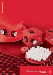
[Vacuum<br />
<strong>pumps</strong> and<br />
<strong>pumps</strong>ets]<br />
Comparison tables for pressures and capacities page 7.00<br />
Small diaphragm <strong>vacuum</strong> <strong>pumps</strong> page 7.01<br />
Vacuum <strong>pumps</strong> with sliding vanes - General description page 7.02<br />
Small <strong>vacuum</strong> <strong>pumps</strong> page 7.03<br />
Vacuum <strong>pumps</strong> VTL 2 and 4 page 7.04<br />
Vacuum <strong>pumps</strong> VTL 5 and 10 page 7.05<br />
Vacuum <strong>pumps</strong> VTLP 5 and 10 page 7.06<br />
Vacuum <strong>pumps</strong> VTL 10/F, 15/F, 20/F page 7.07<br />
Vacuum <strong>pumps</strong> VTLP 10/F, 15/F, 20/F page 7.08<br />
Vacuum <strong>pumps</strong> VTL 25/FG, 30 /FG, 35/FG page 7.09<br />
Vacuum <strong>pumps</strong> VTLP 25/FG, 30 /FG, 35/FG page 7.10<br />
Vacuum <strong>pumps</strong> VTL 40/G1, 50/G1, 65/G1 page 7.11<br />
Vacuum <strong>pumps</strong> VTLP 40/G1, 50/G1, 65/G1 page 7.12<br />
Vacuum <strong>pumps</strong> VTL 75/G1, 90/G1, 105/G1 page 7.13<br />
Vacuum <strong>pumps</strong> VTLP 75/G1, 90/G1, 105/G1 page 7.14<br />
Vacuum <strong>pumps</strong> VTL 6 D.C. page 7.15<br />
Oil-bath <strong>vacuum</strong> <strong>pumps</strong> MV 20 page 7.16<br />
Oil-bath <strong>vacuum</strong> <strong>pumps</strong> MV 40 ÷ 100 page 7.17<br />
Oil-bath <strong>vacuum</strong> <strong>pumps</strong> MV 200 ÷ 300 page 7.18<br />
Vacuum <strong>pumps</strong> VTS 2 and 4 page 7.19<br />
Vacuum <strong>pumps</strong> VTS 6 D.C. page 7.20<br />
Vacuum <strong>pumps</strong> VTS 6 and 10 page 7.21<br />
Vacuum <strong>pumps</strong> VTS 10/F, 15/F, 20F, 25/F page 7.22<br />
Vacuum <strong>pumps</strong> VTS 10/FG, 15/FG, 20/FG page 7.23<br />
Vacuum <strong>pumps</strong> VTS 25/FG, 30/FG, 35/FG page 7.24<br />
Small <strong>pumps</strong>ets page 7.25<br />
Horizontal <strong>pumps</strong>ets page 7.26<br />
Horizontal duplex <strong>pumps</strong>ets page 7.27<br />
Vertical <strong>pumps</strong>ets page 7.28<br />
Vertical duplex <strong>pumps</strong>ets page 7.29<br />
7<br />
< >
[Comparison and conversion tables<br />
for pressures and capacities]<br />
Tabella comparativa delle unità di misura della pressione<br />
S.I. Units (International System)<br />
1 mbar = 100,0 Pa 1,0 mbar 0,001 bar<br />
1 bar = 100000,0 Pa 1000,0 mbar 1,0 bar<br />
1 torr = 133,322 Pa 1,3332 mbar 1,33322 x 10 –3 bar<br />
1 in Hg = 3386,3 Pa 33,863 mbar 3,3863 x 10 –2 bar<br />
1 psi (lbf/in 2 ) = 6894,8 Pa 68,948 mbar 6,8948 x 10 –2 bar<br />
1 atm = 101325,0 Pa 1013,25 mbar 1,01325 bar<br />
1 Kg/cm 2 (at) = 98066,0 Pa 980,66 mbar 0,98066 bar<br />
1 mm H2O = 9,8066 Pa 0,09806 mbar 9,8066 x 10 –5 bar<br />
1 m H2O = 9806,6 Pa 98,066 mbar 9,8066 x 10 –2 bar<br />
1 Pa (N/m 2 ) = 1,0 Pa 0,01 mbar 1,0 x 10 –5 bar<br />
Comparison table of pressure<br />
units<br />
Fattori di conversione delle unità di misura della portata<br />
= m 3 /h = m 3 /min = l/h = l/min = cfm<br />
m 3 /h x 1 0,016 10 3 16,6 0,588<br />
m 3 /min. x 60 1 6 x 10 4 10 3 3.53 x 10<br />
l/h x 10 –3 1,66 x 10 –5 1 0,016 5,88 x 10 –4<br />
l/min x 60 x 10 –3 10 –3 60 1 3,53 x 10 –2<br />
c f m x 1,699 2,83 x 10 –2 1699,0 28,314 1<br />
Conversion factors for capacity<br />
units<br />
[Vacuum <strong>pumps</strong> and <strong>pumps</strong>ets]<br />
7.00<br />
< >
[Small<br />
diaphragm<br />
<strong>vacuum</strong><br />
<strong>pumps</strong>]<br />
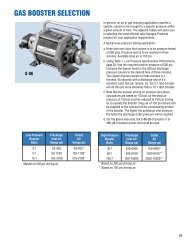
The small <strong>vacuum</strong> <strong>pumps</strong> shown on this page<br />
produce <strong>vacuum</strong> using a diaphragm.<br />
They can be used either as <strong>vacuum</strong> pump or as a<br />
small compressor, and they are able to deliver<br />
100% oil-free compressed air, at a maximum<br />
pressure of 1 bar.<br />
They consist of:<br />
• A small single-phase electric motor, with<br />
protection class IP 00 (assembling execution),<br />
air-cooled.<br />
• A pump body made of plastic material resistant<br />
to corrosion, complete with fittings at both<br />
suction and blowing ports.<br />
• A diaphragm, integral to a connection rod, made<br />
of special materials, resistant to wear and<br />
corrosion.<br />
• A connection rod with built-in “long-life” bearing,<br />
driven by a balanced eccentric system splined to<br />
the motor shaft.<br />
• Aluminium bracket to hold the pump, available in<br />
Model<br />
Capacity Final pressure Max pressure Power Input Weight<br />
It/l’ mbar (a) bar (g) watt A Kg.<br />
H 35 M 18.0 300 1 30 0.45 1.3<br />
H 40 DM 17.5 300 1 38 0.40 1.6<br />
H 35 MR 18.0 300 1 30 0.45 1.3<br />
H 40 DMR 17.5 300 1 38 0.40 1.6<br />
two versions.<br />
The diaphragm small <strong>vacuum</strong> <strong>pumps</strong> are very<br />
noiseless (
[Vacuum <strong>pumps</strong><br />
with sliding<br />
vanes<br />
General<br />
description]<br />
WORKING PRINCIPLE<br />
The piston (or rotor) eccentrically rotates in a<br />
cylinder (stator) and is provided with grooves<br />
where vanes slide free and due to the<br />
centrifugal force, are pushed against the inside<br />
wall of the cylinder thus forming as many<br />
chambers as vanes are.<br />
During rotation the volume of these chambers<br />
changes according to the position in which they<br />
are in relation to the eccentric axis.<br />
The increase in the volume of chambers<br />
expands air enclosed in them thus creating a<br />
depression (suction phase); the volume<br />
decrease instead, causes an air compression<br />
(exhaust phase or delivery).<br />
The internal construction principle is the same<br />
both for rotating compressors and for <strong>vacuum</strong><br />
<strong>pumps</strong>.<br />
ROTOR HOUSING<br />
In smaller and compact <strong>pumps</strong>, rotor is<br />
overhanging splined to the shaft end of the<br />
motor, while in constructions with high powers<br />
and for different starting systems, rotor is<br />
supported by bearings on both sides, in this<br />
case pump and motor are two independent<br />
units and the two shafts are coupled by means<br />
of an elastic joint.<br />
LUBRICATION SYSTEMS<br />
The main lubrication systems we use, are by<br />
depression with loop lubrication or with oil loss<br />
for the <strong>vacuum</strong> <strong>pumps</strong> series VTL, and with oilbath<br />
for <strong>pumps</strong> series MV.<br />
In the oil loop lubrication, the oil, sucked in the<br />
chamber by means of the adjustable oilers<br />
which control the flow rate, is drained together<br />
with the sucked air into the recovery tank and<br />
by means of a separating filter contained in it,<br />
it is divided from the air and put into circulation<br />
again.<br />
In the oil loss lubrication, lubricating oil is<br />
contained in a suitable transparent container<br />
(controlled by a magnetic level switch). It works<br />
the same way as above but it is collected in a<br />
recovery tank without being put into circulation<br />
again.<br />
This kind of lubrication is recommended when<br />
the sucked air contains water condensates,<br />
solvent vapours or any other product which<br />
would affect the oil properties.<br />
In the oil-bath lubrication, the oil is sucked<br />
directly from the recovery tank by calibrated<br />
nozzles, which control the flow rate, and it is<br />
kept and separated from air in the exhaust<br />
phase by microfibre oil-separating cartridges,<br />
which are contained in the tank itself.<br />
In this lubricating system, the oil quantity in<br />
circulation is definitely higher than in the two<br />
other above mentioned systems; this involves<br />
a better sealing between stator and rotor and<br />
a lower friction between rotating parts and<br />
fixed ones, consequently with <strong>vacuum</strong> degree<br />
increase, lower heating and lower noise.<br />
DRY VACUUM PUMPS<br />
They normally have small suction capacities<br />
and they do not need to be lubricated.<br />
COOLING<br />
The cooling system we use for our <strong>pumps</strong> is by<br />
airflow on their surface.<br />
Heat is dispersed from the external surface,<br />
suitably finned, by means of the motor fan in<br />
the smaller <strong>pumps</strong> and by means of a radial fan<br />
splined to the pump shaft, in the larger ones.<br />
MATERIALS USED<br />
Stator and locking flanges are in cast iron,<br />
shaft and rotor are made with carbon steel,<br />
vanes are made with fibre for lubricated <strong>pumps</strong><br />
and graphite for dry running <strong>pumps</strong>.<br />
ELECTRIC MOTORS<br />
All <strong>pumps</strong> with capacities up to 20 cum/h can<br />
be supplied either with three-phase or with<br />
single-phase motors; for bigger capacities with<br />
three-phase motors only. All models can be<br />
supplied with special voltages or frequencies.<br />
[Vacuum <strong>pumps</strong> and <strong>pumps</strong>ets]<br />
7.02<br />
< >
[Small<br />
<strong>vacuum</strong> <strong>pumps</strong>]<br />
They are very small <strong>vacuum</strong> <strong>pumps</strong> with rotating<br />
vanes that can also be used as a small<br />
compressor for pressures up to 2 bar.<br />
They are made up of a single-phase induction<br />
electric motor with capacitor (upon request they<br />
can be supplied with D.C. motor), a self-lubricating<br />
stator in sintered metal, a rotor in white metal<br />
splined to the motor shaft and grooved for housing<br />
the hardened steel vanes and a silencer on the<br />
exhaust.<br />
The operating principle is the same as the <strong>vacuum</strong><br />
<strong>pumps</strong> with rotating vanes of the bigger series.<br />
They are noiseless, completely lubrication-free and<br />
they do not need any maintenance.<br />
Due to their very small size and weight, they are<br />
particularly suitable for the installation on portable<br />
equipment.<br />
They are suitable for intermittent and not heavy<br />
use.<br />
Model.<br />
Capacity Final pressure Max pressure Power Capac. Weight<br />
It/l’ mbar (a) bar (g) watt µ F Kg.<br />
H 25 R 13.5 210 2 28 2.50 1.3<br />
H 45 R 15.0 150 2 35 3.15 2.0<br />
H 45 DR 20.0 150 2 38 3.15 2.1<br />
H 45 DR/D 13.5 70 2 40 3.15 2.1<br />
[Vacuum <strong>pumps</strong> and <strong>pumps</strong>ets]<br />
7.03<br />
< >
[Vacuum<br />
<strong>pumps</strong><br />
VTL 2 and 4]<br />
VTL 2 4<br />
Capacity cum/h 2 4<br />
Final pressure mbar abs. 150 150<br />
Motor execution 3 ~ 230/400 ± 10%, 50 Hz<br />
Volt 1 ~ 230 ± 10%, 50 Hz<br />
Motor power 3 ~ 0.13 0.18<br />
Kw 1 ~ 0.13 0.15<br />
Motor power 3 ~ 0.18 0.25<br />
Hp 1 ~ 0.18 0.20<br />
Rpm 2900 2900<br />
Max weight 3 ~ 5.7 7.3<br />
Kg 1 ~ 6.0 7.5<br />
A 260 285<br />
B 145 160<br />
C 126 132<br />
D 62 66<br />
E 71 80<br />
F 127 139<br />
G Ø 6.5 7.5<br />
H 72 80<br />
I 90 100<br />
L 43 48<br />
M 12 12<br />
N 76 86<br />
R Ø gas 1/4” 3/8”<br />
These small <strong>vacuum</strong> <strong>pumps</strong> have a suction<br />
capacity of 2 and 4 cum/h.<br />
They are wick oiled with loop lubrication system<br />
and because the rotor is overhanging splined to<br />
the motor shaft, they are of small dimensions.<br />
Motor and pump are cooled by the motor fan<br />
(surface cooling).<br />
These <strong>pumps</strong> are provided with a small tank<br />
placed on the same axis of the pump, containing<br />
the lubricating oil as well as a separation filter<br />
that prevents oil mists and reduces noise as well.<br />
It is recommended to install a check valve and a<br />
suitable filter on the pump suction inlet.<br />
Pumps VTL 2 and 4 can also be supplied with<br />
single-phase electric motor.<br />
The table shows all data and technical features<br />
of this series of <strong>pumps</strong>.<br />
[Vacuum <strong>pumps</strong> and <strong>pumps</strong>ets]<br />
7.04<br />
< >
[Vacuum<br />
<strong>pumps</strong><br />
VTL 5 and 10]<br />
VTL 5 10<br />
Capacity cum/h 5 10<br />
Final pressure mbar abs. 80 80<br />
Motor execution 3 ~ 230/400 ± 10%, 50 Hz<br />
Volt 1 ~ 230 ± 10%, 50 Hz<br />
Motor power 3 ~ 0.25 0.35<br />
Kw 1 ~ 0.25 0.25<br />
Motor power 3 ~ 0.35 0.50<br />
Hp 1 ~ 0.35 0.35<br />
Rpm 1450 1450<br />
Max weight 3 ~ 14.5 20.5<br />
Kg 1 ~ 15.0 21.0<br />
A 260 310<br />
B 245 262<br />
C 245 245<br />
D 52 70<br />
E 155 155<br />
F 53 85<br />
G Ø 8.5 8.5<br />
H 122 122<br />
I 115 115<br />
L 45 45<br />
M 85 102<br />
N 27 52<br />
R Ø gas 3/8” 1/2”<br />
These <strong>vacuum</strong> <strong>pumps</strong> have a suction capacity of<br />
5 and 10 cum/h.<br />
They are lubricated by depression with loop<br />
lubrication system adjustable by means of an oiler<br />
placed in correspondence of the suction inlet.<br />
The rotor is overhanging splined to the motor<br />
shaft, therefore the overall dimensions are very<br />
small.<br />
Motor and pump are cooled by the motor fan<br />
(surface cooling).<br />
A tank for the oil recovery is installed on the pump<br />
outlet, this tank contains a separation filter that<br />
avoids forming of oil mists and reduces noise as<br />
well.<br />
It is recommended to install a check valve and a<br />
suitable filter on the pump suction inlet.<br />
Pumps VTL 5 and 10 can also be supplied with<br />
single-phase electric motor.<br />
The table shows all data and technical features of<br />
this series of <strong>pumps</strong>.<br />
[Vacuum <strong>pumps</strong> and <strong>pumps</strong>ets]<br />
7.05<br />
< >
[Vacuum<br />
<strong>pumps</strong><br />
VTLP 5 and 10<br />
with oil loss<br />
lubrication]<br />
VTLP 5 10<br />
Capacity cum/h 5 10<br />
Final pressure mbar abs. 80 80<br />
Motor execution 3 ~ 230/400 ± 10%, 50 Hz<br />
Volt 1 ~ 230 ± 10%, 50 Hz<br />
Motor power 3 ~ 0.25 0.35<br />
Kw 1 ~ 0.25 0.25<br />
Motor power 3 ~ 0.35 0.50<br />
Hp 1 ~ 0.35 0.35<br />
Rpm 1450 1450<br />
Max weight 3 ~ 15.6 21.6<br />
Kg 1 ~ 16.1 22.1<br />
A 260 310<br />
B 245 262<br />
C 410 410<br />
D 52 70<br />
E 155 155<br />
F 53 85<br />
G Ø 8.5 8.5<br />
H 122 122<br />
I 115 115<br />
L 45 45<br />
M 85 102<br />
N 27 52<br />
R Ø gas 3/8” 1/2”<br />
O Ø 150 150<br />
These <strong>vacuum</strong> <strong>pumps</strong> have a suction capacity of<br />
5 and 10 cum/h.<br />
They are lubricated by depression with oil loss<br />
and lubrication is adjustable by means of an oiler<br />
placed in correspondence of the suction inlet.<br />
The rotor is overhanging splined to the motor<br />
shaft, therefore the overall dimensions are very<br />
small.<br />
Motor and pump are cooled by the motor fan<br />
(surface cooling).<br />
A tank for the oil recovery is installed on the<br />
pump outlet, this tank contains a separation filter<br />
that avoids forming of oil mists and reduces<br />
noise as well.<br />
A safety valve is incorporated on this tank for the<br />
automatic drainage of the used oil between<br />
periodical changing. The lubricating oil is<br />
contained in a suitable transparent container<br />
fixed to the pump by means of its support and is<br />
controlled by a magnetic level switch.<br />
In <strong>pumps</strong> with oil loss lubrication, lubricating oil,<br />
sucked into the pump by means of the drop oiler,<br />
is drained into the recovery tank together with<br />
the air without being put into circulation again.<br />
These <strong>pumps</strong> are recommended when in the<br />
sucked air there are water condensates, solvent<br />
vapours or any other thing that may contaminate<br />
the lubricating oil.<br />
It is recommended to install a check valve and a<br />
suitable filter on the pump suction inlet.<br />
Pumps VTLP 5 and 10 can also be supplied with<br />
single-phase electric motor.<br />
[Vacuum <strong>pumps</strong> and <strong>pumps</strong>ets]<br />
7.06<br />
< >
[Vacuum<br />
<strong>pumps</strong><br />
VTL 10/F, 15/F,<br />
20/F]<br />
VTL 10/F 15/F 20/F<br />
Capacity cum/h 10 15 20<br />
Final pressure mbar abs. 50 50 50<br />
Motor execution 3 ~ 230/400 ± 10%, 50 Hz<br />
Volt 1 ~ 230 ± 10%, 50 Hz<br />
Motor power 3 ~ 0.55 0.55 0.88<br />
Kw 1~ 0.55 0.55 0.66<br />
Motor power 3 ~ 0.75 0.75 1.20<br />
Hp 1~ 0.75 0.75 0.90<br />
Rpm 1450 1450 1450<br />
Max weight 3 ~ 25.0 27.0 30.0<br />
Kg 1~ 25.5 27.5 30.5<br />
A 385 405 425<br />
B 285 285 285<br />
C 259 259 259<br />
D 25 25 25<br />
E 340 340 340<br />
F 20 40 60<br />
G Ø 8.5 8.5 8.5<br />
H 133 133 133<br />
I 130 130 130<br />
L 55 55 55<br />
M 100 100 100<br />
N 53 63 73<br />
R Ø gas 1/2” 1/2” 1/2”<br />
They are <strong>vacuum</strong> <strong>pumps</strong> having a suction capacity<br />
of 10, 15 and 20 cum/h.<br />
Lubrication occurs by depression with loop<br />
lubrication system and it is adjustable by means of<br />
an oiler placed in correspondence of the suction<br />
inlet.<br />
The rotor is splined to the motor shaft and is<br />
supported by independent bearings on both sides.<br />
The pump is surface cooled.<br />
Heat is dispersed from the outer surface, suitably<br />
finned, by means of a radial fan placed between<br />
motor and pump.<br />
A tank for the oil recovery is installed on the pump<br />
outlet, it contains a separation filter that avoids<br />
forming of oil mists and reduces noise as well.<br />
It is recommended to install a check valve and a<br />
suitable filter on the pump suction inlet.<br />
This series of <strong>pumps</strong> can also be supplied with<br />
single-phase electric motors.<br />
The table shows all data and technical features of<br />
this series of <strong>pumps</strong>.<br />
[Vacuum <strong>pumps</strong> and <strong>pumps</strong>ets]<br />
7.07<br />
< >
[Vacuum<br />
<strong>pumps</strong> VTLP<br />
10/F, 15/F, 20/F<br />
with oil loss<br />
lubrication]<br />
VTLP 10/F 15/F 20/F<br />
Capacity cum/h 10 15 20<br />
Final pressure mbar abs. 50 50 50<br />
Motor execution 3 ~ 230/400 ± 10%, 50 Hz<br />
Volt 1 ~ 230 ± 10%, 50 Hz<br />
Motor power 3 ~ 0.55 0.55 0.88<br />
Kw 1 ~ 0.55 0.55 0.66<br />
Motor power 3 ~ 0.75 0.75 1.20<br />
Hp 1 ~ 0.75 0.75 0.90<br />
Rpm 1450 1450 1450<br />
Max weight 3 ~ 26.1 28.1 31.1<br />
Kg 1 ~ 26.6 28.6 31.6<br />
A 385 405 425<br />
B 285 285 285<br />
C 440 440 440<br />
D 25 25 25<br />
E 340 340 340<br />
F 20 40 60<br />
G Ø 8.5 8.5 8.5<br />
H 133 133 133<br />
I 130 130 130<br />
L 55 55 55<br />
M 100 100 100<br />
N 53 63 73<br />
R Ø gas 1/2” 1/2” 1/2”<br />
O Ø 150 150 150<br />
These <strong>vacuum</strong> <strong>pumps</strong> have a suction capacity of<br />
10, 15 and 20 cum/h.<br />
They are lubricated by depression with oil loss<br />
and lubrication is adjustable by means of an oiler<br />
placed in correspondence of the suction inlet.<br />
The rotor is splined to the motor shaft and is<br />
supported by independent bearings on both<br />
sides.<br />
The pump is surface cooled.<br />
Heat is dispersed from the outer surface, suitably<br />
finned, by means of a radial fan placed between<br />
motor and pump.<br />
A tank for the oil recovery is installed on the<br />
pump outlet, this tank contains a separation filter<br />
that avoids forming of oil mists and reduces<br />
noise as well.<br />
A safety valve is incorporated on this tank for the<br />
automatic drainage of the used oil between<br />
periodical changing. The lubricating oil is<br />
contained in a suitable transparent container<br />
fixed to the pump by means of its support and is<br />
controlled by a magnetic level switch.<br />
In <strong>pumps</strong> with oil loss lubrication, lubricating oil,<br />
sucked into the pump by means of the drop oiler,<br />
is drained into the recovery tank together with<br />
the air without being put into circulation again.<br />
These <strong>pumps</strong> are recommended when in the<br />
sucked air there are water condensates, solvent<br />
vapours or any other thing that may contaminate<br />
the lubricating oil.<br />
It is recommended to install a check valve and a<br />
suitable filter on the pump suction inlet.<br />
This series of <strong>pumps</strong> can also be supplied with<br />
single-phase electric motors.<br />
[Vacuum <strong>pumps</strong> and <strong>pumps</strong>ets]<br />
7.08<br />
< >
[Vacuum<br />
<strong>pumps</strong> VTL<br />
25/FG, 30/FG,<br />
35/FG]<br />
VTL 25/FG 30/FG 35/FG<br />
Capacity cum/h 25 30 35<br />
Final pressure mbar abs. 50 50 50<br />
Motor execution Volt 230/400 ± 10%, 50 Hz<br />
Motor power Kw 0.88 1.0 1.0<br />
Motor power Hp 1.20 1.4 1.4<br />
Rpm 1450 1450 1450<br />
Max weight Kg 31 35 37<br />
A 470 490 510<br />
B 290 290 290<br />
C 280 280 280<br />
D 65 65 65<br />
E 385 385 385<br />
F 20 40 60<br />
G ø 8.5 8.5 8.5<br />
H 133 133 133<br />
I 130 130 130<br />
L 55 55 55<br />
M 105 105 105<br />
N 73 83 93<br />
R ø gas 3/4” 3/4” 3/4”<br />
These are <strong>vacuum</strong> <strong>pumps</strong> with a flow capacity of<br />
25, 30 and 35 cum/h.<br />
These <strong>pumps</strong> are lubricated by means of a wick<br />
feed, which is adjustable using two lubricators<br />
positioned in correspondence with the bearings.<br />
The rotor is splined on its shaft and it is<br />
supported by two bearings.<br />
The pump and electrical motor are two<br />
independent units coupled together with an<br />
elastic joint.<br />
The pump is surface cooled. Heat is dispersed<br />
from the outer surface, suitably finned, by means<br />
of a radial fan placed between motor and pump.<br />
A tank for the oil recovery is installed on the<br />
pump outlet, it contains a separation filter that<br />
avoids forming of oil mists and reduces noise as<br />
well. It is recommended to install a check valve<br />
and a suitable filter on the pump suction inlet to<br />
keep possible impurities sucked.<br />
The table shows all data and technical features<br />
of this series of <strong>pumps</strong>.<br />
[Vacuum <strong>pumps</strong> and <strong>pumps</strong>ets]<br />
7.09<br />
< >
[Vacuum<br />
<strong>pumps</strong> VTLP<br />
25/FG, 30/FG,<br />
35/FG with<br />
oil loss<br />
lubrication]<br />
VTLP 25/FG 30/FG 35/FG<br />
Capacity cum/h 25 30 35<br />
Final pressure mbar abs. 50 50 50<br />
Motor execution Volt 230/400 ± 10%, 50 Hz<br />
Motor power Kw 0.88 1.0 1.0<br />
Motor power Hp 1.20 1.4 1.4<br />
Rpm 1450 1450 1450<br />
Max weight Kg 32 36 38<br />
A 470 490 510<br />
B 290 290 290<br />
C 445 445 445<br />
D 65 65 65<br />
E 385 385 385<br />
F 20 40 60<br />
G ø 8.5 8.5 8.5<br />
H 133 133 133<br />
I 130 130 130<br />
L 55 55 55<br />
M 105 105 105<br />
N 73 83 93<br />
R ø gas 3/4” 3/4” 3/4”<br />
0 ø 150 150 150<br />
These <strong>vacuum</strong> <strong>pumps</strong> have a suction capacity of<br />
25, 30 and 35 cum/h.<br />
They are lubricated by depression with oil loss<br />
and lubrication is adjustable by means of two<br />
oilers placed in correspondence of the supporting<br />
bearings. The rotor is splined on its shaft and it<br />
is supported by two bearings. The pump and<br />
electrical motor are two independent units<br />
coupled together by an elastic joint.<br />
The pump is surface cooled.<br />
Heat is dispersed from the outer surface, suitably<br />
finned, by means of a radial fan placed between<br />
motor and pump.<br />
A tank for the oil recovery is installed on the<br />
pump outlet, this tank contains a separation filter<br />
that avoids forming of oil mists and reduces noise<br />
as well.<br />
A safety valve is incorporated on this tank for the<br />
automatic drainage of the used oil between<br />
periodical changing. The lubricating oil is<br />
contained in a suitable transparent container<br />
fixed to the pump by means of its support and is<br />
controlled by a magnetic level switch.<br />
In <strong>pumps</strong> with oil loss lubrication, lubricating oil,<br />
sucked into the pump by means of the drop<br />
oilers, is drained into the recovery tank together<br />
with the air without being put into circulation<br />
again. These <strong>pumps</strong> are recommended when in<br />
the sucked air there are water condensates,<br />
solvent vapours or any other thing that may<br />
contaminate the lubricating oil.<br />
It is recommended to install a check valve and a<br />
suitable filter on the pump suction inlet.<br />
[Vacuum <strong>pumps</strong> and <strong>pumps</strong>ets]<br />
7.10<br />
< >
[Vacuum<br />
<strong>pumps</strong> VTL<br />
40/G1, 50/G1,<br />
65/G1]<br />
VTL 40/G1 50/G1 65/G1<br />
Capacity cum/h 40 50 65<br />
Final pressure mbar abs. 50 50 50<br />
Motor execution Volt 230/400±10%, 50Hz<br />
Motor power Kw 1.1 1.5 1.5<br />
Motor power Hp 1.5 2 2<br />
Rpm 1450 1450 1450<br />
Max weight Kg 51 54 71.5<br />
A 520 560 610<br />
B 365 365 380<br />
C 350 350 350<br />
D 60 115 150<br />
E 415 415 415<br />
F 45 30 45<br />
G ø 12.5 12.5 12.5<br />
H 186 186 186<br />
I 210 210 210<br />
L 30 30 30<br />
M 125 125 140<br />
N 70 80 70<br />
R ø gas 1” 1” 1”1/4<br />
They are <strong>vacuum</strong> <strong>pumps</strong> having a suction<br />
capacity of 40, 50, and 65 cum/h.<br />
Lubrication occurs by depression with loop<br />
lubrication system and it is adjustable by means<br />
of two oilers placed in correspondence of the<br />
supporting bearings.<br />
The rotor is splined to its own shaft and is<br />
supported by bearings on both sides.<br />
In this series, pump and motor are two<br />
independent units and the two shafts are coupled<br />
by means of an elastic joint.<br />
Cooling occurs by the surface.<br />
Heat is dispersed from the outer surface, suitably<br />
finned, by means of a radial fan placed between<br />
motor and pump.<br />
A tank for the oil recovery is installed on the<br />
pump outlet, with the purpose to reduce noise<br />
and to eliminate smokes.<br />
It is necessary to install a check valve and a<br />
suitable filter on the pump suction inlet to keep<br />
possible impurities sucked. This series of <strong>pumps</strong><br />
can be supplied with three-phase electric motors<br />
only.<br />
The table shows all data and technical features<br />
of this series of <strong>pumps</strong>.<br />
[Vacuum <strong>pumps</strong> and <strong>pumps</strong>ets]<br />
7.11<br />
< >
[Vacuum<br />
<strong>pumps</strong> VTLP<br />
40/G1, 50/G1,<br />
65/G1 with<br />
oil loss<br />
lubrication]<br />
VTLP 40/G1 50/G1 65/G1<br />
Capacity cum/h 40 50 65<br />
Final pressure mbar abs. 50 50 50<br />
Motor execution Volt 230/400±10%, 50Hz<br />
Motor power Kw 1.1 1.5 1.5<br />
Motor power Hp 1.5 2 2<br />
Rpm 1450 1450 1450<br />
Max weight Kg 52.5 55.1 72.6<br />
A 520 560 610<br />
B 365 365 380<br />
C 525 525 525<br />
D 60 115 150<br />
E 415 415 415<br />
F 45 30 45<br />
G ø 12.5 12.5 12.5<br />
H 186 186 186<br />
I 210 210 210<br />
L 30 30 30<br />
M 125 125 140<br />
N 70 80 70<br />
R ø gas 1” 1” 1”1/4<br />
0 ø 150 150 150<br />
They are <strong>vacuum</strong> <strong>pumps</strong> having a suction<br />
capacity of 40, 50, and 65 cum/h.<br />
They are lubricated by depression with oil loss<br />
and lubrication is adjustable by means of two<br />
oilers placed in correspondence of the supporting<br />
bearings. The rotor is splined to its own shaft<br />
and is supported by bearings on both sides.<br />
In this series, pump and motor are two<br />
independent units and the two shafts are coupled<br />
by means of an elastic joint. Cooling occurs by<br />
the surface. Heat is dispersed from the outer<br />
surface, suitably finned, by means of a radial fan<br />
placed between motor and pump.<br />
A tank for the oil recovery is installed on the<br />
pump outlet, with the purpose to reduce noise<br />
and to eliminate smokes.<br />
A safety valve is incorporated on this tank for the<br />
automatic drainage of the used oil between<br />
periodical changing. The lubricating oil is<br />
contained in a suitable transparent container<br />
fixed to the pump by means of its support and is<br />
controlled by a magnetic level switch.<br />
In <strong>pumps</strong> with oil loss lubrication, lubricating oil,<br />
sucked into the pump by means of the drop<br />
oilers, is drained into the recovery tank together<br />
with the air without being put into circulation<br />
again. These <strong>pumps</strong> are recommended when in<br />
the sucked air there are water condensates,<br />
solvent vapours or any other thing that may<br />
contaminate the lubricating oil.<br />
It is necessary to install a check valve and a<br />
suitable filter on the pump suction inlet to keep<br />
possible impurities sucked. This series of <strong>pumps</strong><br />
can be supplied with three-phase electric motors<br />
only.<br />
[Vacuum <strong>pumps</strong> and <strong>pumps</strong>ets]<br />
7.12<br />
< >
[Vacuum<br />
<strong>pumps</strong> VTL<br />
75/G1, 90/G1,<br />
105/G1]<br />
VTL 75/G1 90/G1 105/G1<br />
Capacity cum/h 75 90 105<br />
Final pressure mbar abs. 50 50 50<br />
Motor execution volt 230/400±10%, 50Hz<br />
Motor power Kw 2.2 3.0 3.0<br />
Motor power Hp 3 4 4<br />
Rpm 1450 1450 1450<br />
Max weight Kg 76.5 84.0 97.6<br />
A 640 660 690<br />
B 385 400 400<br />
C 400 400 445<br />
D 163 163 163<br />
E 415 415 415<br />
F 62 82 112<br />
G ø 12.5 12.5 12.5<br />
H 186 186 186<br />
I 210 210 210<br />
L 30 30 30<br />
M 145 150 160<br />
N 80 92 122<br />
R ø gas 1”1/4 1”1/4 1”1/2<br />
They are <strong>vacuum</strong> <strong>pumps</strong> having a suction<br />
capacity of 75, 90 and 105 cum/h.<br />
Lubrication occurs by depression with loop<br />
lubrication system and it is adjustable by means<br />
of two oilers placed in correspondence of the<br />
supporting bearings.<br />
The rotor is splined to its own shaft and is<br />
supported by bearings on both sides.<br />
In this series, pump and motor are two<br />
independent units and the two shafts are coupled<br />
by means of an elastic joint.<br />
Cooling occurs by the surface.<br />
Heat is dispersed from the outer surface, suitably<br />
finned, by means of a radial fan placed between<br />
motor and pump.<br />
A big tank for the oil recovery is installed on the<br />
pump outlet, with built-in oil condensate trap,<br />
has the purpose to reduce noise and to eliminate<br />
smokes.<br />
It is necessary to install a check valve and a<br />
suitable filter on the pump suction inlet to keep<br />
possible impurities sucked. This series of <strong>pumps</strong><br />
can be supplied only with three-phase electric<br />
motors.<br />
The table shows all data and technical features<br />
of this series of <strong>pumps</strong>.<br />
[Vacuum <strong>pumps</strong> and <strong>pumps</strong>ets]<br />
7.13<br />
< >
[Vacuum<br />
<strong>pumps</strong> VTLP<br />
75/G1, 90/G1,<br />
105/G1 with<br />
oil loss<br />
lubrication]<br />
VTLP 75/G1 90/G1 105/G1<br />
Capacity cum/h 75 90 105<br />
Final pressure mbar abs. 50 50 50<br />
Motor execution Volt 230/400±10%, 50Hz<br />
Motor power Kw 2.2 3.0 3.0<br />
Motor power Hp 3 4 4<br />
Rpm 1450 1450 1450<br />
Max weight Kg 78.3 85.8 99.4<br />
A 640 660 690<br />
B 415 430 430<br />
C 575 575 620<br />
D 163 163 163<br />
E 415 415 415<br />
F 62 82 112<br />
G ø 12.5 12.5 12.5<br />
H 186 186 186<br />
I 210 210 210<br />
L 30 30 30<br />
M 145 150 160<br />
N 80 92 122<br />
R ø gas 1”1/4 1”1/4 1”1/2<br />
O ø 200 200 200<br />
P 30 30 30<br />
They are <strong>vacuum</strong> <strong>pumps</strong> having a suction<br />
capacity of 75, 90 and 105 cum/h.<br />
They are lubricated by depression with oil loss<br />
and lubrication is adjustable by means of two<br />
oilers placed in correspondence of the supporting<br />
bearings.<br />
The rotor is splined to its own shaft and is<br />
supported by bearings on both sides.<br />
In this series, pump and motor are two<br />
independent units and the two shafts are coupled<br />
by means of an elastic joint.<br />
Cooling occurs by the surface.<br />
Heat is dispersed from the outer surface, suitably<br />
finned, by means of a radial fan placed between<br />
motor and pump.<br />
A big tank for the oil recovery is installed on the<br />
pump outlet, with built-in oil condensate trap,<br />
has the purpose to reduce noise and to eliminate<br />
smokes.<br />
A safety valve is incorporated on this tank for the<br />
automatic drainage of the used oil between<br />
periodical changing. The lubricating oil is<br />
contained in a suitable transparent container<br />
fixed to the pump by means of its support and is<br />
controlled by a magnetic level switch.<br />
In <strong>pumps</strong> with oil loss lubrication, lubricating oil,<br />
sucked into the pump by means of the drop<br />
oilers, is drained into the recovery tank together<br />
with the air without being put into circulation<br />
again.<br />
These <strong>pumps</strong> are recommended when in the<br />
sucked air there are water condensates, solvent<br />
vapours or any other thing that may contaminate<br />
the lubricating oil.<br />
It is necessary to install a check valve and a<br />
suitable filter on the pump suction inlet to keep<br />
possible impurities sucked.<br />
[Vacuum <strong>pumps</strong> and <strong>pumps</strong>ets]<br />
7.14<br />
< >
[Vacuum<br />
<strong>pumps</strong><br />
VTL 6 D.C.]<br />
VTL<br />
6 D.C.<br />
Capacity cum/h 6<br />
Final pressure mbar abs. 2<br />
Motor execution Volt 24 D.C.<br />
Motor power Kw 0.28<br />
Max input at 24V D.C. A 15<br />
Rpm 3000<br />
Max weight Kg 10.5<br />
A 335<br />
B 168<br />
C 195<br />
D 124<br />
E 65<br />
F 146<br />
G 8<br />
H 128<br />
I 112<br />
L 12<br />
M 44<br />
N 32<br />
O 14.5<br />
R ø gas 3/8”<br />
The compact size, very good final <strong>vacuum</strong> level,<br />
and the D.C. electrical motor are the main features<br />
of this sliding vane <strong>vacuum</strong> pump.<br />
The pump has an oil loop depression lubrication<br />
system.<br />
Both the pump and motor are surface cooled by<br />
the motor fan.<br />
The <strong>pumps</strong> are equipped with a small holding<br />
tank, which contains the lubricating oil, and a<br />
condensing separator that eliminates exhaust oil<br />
mist and also acts as a silencer making these<br />
<strong>pumps</strong> very quite in operation.<br />
The pump has an integral check valve on the inlet<br />
port and upon request suitable <strong>vacuum</strong> filtration<br />
can be supplied.<br />
VTL 6 D.C. <strong>pumps</strong> can be supplied only with D.C.<br />
electrical motor (service S1) in conformity with<br />
EMC directive (89/336/EEC).<br />
The table shows all the data and the technical<br />
features of this range of <strong>pumps</strong>.<br />
[Vacuum <strong>pumps</strong> and <strong>pumps</strong>ets]<br />
7.15<br />
< >
[Oil-bath<br />
<strong>vacuum</strong> <strong>pumps</strong><br />
MV 20, 20A]<br />
MV 20 20A<br />
Capacity cum/h 20 20<br />
Final pressure mbar abs. 40 0.7<br />
Motor execution Volt 230/400 ± 10%, 50 Hz<br />
Motor power Kw 0.75 0.75<br />
Motor power Hp 1 1<br />
Rpm 2800 2800<br />
Max weight Kg 21.5 21.5<br />
A 425 425<br />
B 235 235<br />
C 215 215<br />
D 145 145<br />
E 220 220<br />
F 60 60<br />
G ø 6.5 6.5<br />
H 170 170<br />
I 113 113<br />
L 82 82<br />
M 40 40<br />
N 60 60<br />
O 30 30<br />
R ø gas 1/2” 1/2”<br />
MV series <strong>vacuum</strong> <strong>pumps</strong> are single stage <strong>pumps</strong><br />
with rotating vanes, with oil-bath loop lubrication<br />
system.<br />
These <strong>pumps</strong> are driven by a standard electric<br />
motor coupled together via an elastic drive joint.<br />
A centrifugal fan, splined to the pump shaft,<br />
assures a proper airflow for the best cooling of<br />
the pump unit (surface forced cooling).<br />
A big tank for the oil recovery, installed on the<br />
pump outlet, with built-in oil condensate trap,<br />
reduces noise and eliminates smoke.<br />
The oil contained in the system carries out the<br />
function of lubrication, cooling and sealing<br />
between the rotating and the fixed parts of the<br />
pump.<br />
On the suction inlet, the check valve is integral<br />
part of the pump as a standard, while upon<br />
request, a suitable filter is supplied to stop<br />
possible sucked impurities.<br />
All MV series <strong>pumps</strong> can be prepared for<br />
installing a gas ballast valve (upon request),<br />
which allows a high compatibility to steam.<br />
Thanks to the above mentioned devices, as well<br />
as to a compact and sturdy construction, MV<br />
series of <strong>pumps</strong> are particularly suitable to<br />
operate on continuous duty and under very heavy<br />
conditions.<br />
In the table on the side, dimensional data and<br />
values concerning the technical specifications of<br />
this series of <strong>pumps</strong> are shown.<br />
[Vacuum <strong>pumps</strong> and <strong>pumps</strong>ets]<br />
7.16<br />
< >
[Oil-bath<br />
<strong>vacuum</strong><br />
<strong>pumps</strong> MV 40,<br />
40A, 60, 60A,<br />
100, 100A ]<br />
MV 40 40A 60 60A 100 100A<br />
Capacity cum/h 40 40 60 60 100 100<br />
Final pressure mbar abs. 40 0.7 40 0.7 40 0.7<br />
Motor execution Volt 230/400 ± 10%, 50 Hz<br />
Motor power Kw 1.1 1.1 1.5 1.5 2.2 2.2<br />
Motor power Hp 1.5 1.5 2 2 3 3<br />
Rpm 1450 1450 1450 1450 1450 1450<br />
Max weight Kg 45 45 53 53 80 80<br />
A 628 628 688 688 790 790<br />
B 338 338 338 338 430 430<br />
C 300 300 300 300 330 330<br />
D 80 80 140 140 -- --<br />
E 415 415 415 415 -- --<br />
F 133 133 133 133 -- --<br />
G ø 10 10 10 10 M10 M10<br />
H 250 250 250 250 290 290<br />
I 210 210 210 210 275 275<br />
L 90.5 90.5 123 123 115 115<br />
M 37.5 37.5 97 97 40 40<br />
N 188 188 188 188 240 240<br />
0 100 100 100 100 130 130<br />
P 143 143 143 143 180 180<br />
R ø gas 1”1/4 1”1/4 1”1/4 1”1/4 1”1/4 1”1/4<br />
N.B.: Pumps mod. MV100-MV1OOA are supplied without fixing plates.<br />
MV series <strong>vacuum</strong> <strong>pumps</strong> are single stage <strong>pumps</strong><br />
with rotating vanes, with oil-bath loop lubrication<br />
system.<br />
These <strong>pumps</strong> are driven by a standard electric<br />
motor coupled together via an elastic drive joint.<br />
A centrifugal fan, splined to the pump shaft,<br />
assures a proper airflow for the best cooling of<br />
the pump unit (surface forced cooling).<br />
A big tank for the oil recovery, installed on the<br />
pump outlet, with built-in oil condensate trap,<br />
reduces noise and eliminates smoke.<br />
The oil contained in the system carries out the<br />
function of lubrication, cooling and sealing<br />
between the rotating and the fixed parts of the<br />
pump.<br />
On the suction inlet, the check valve is integral<br />
part of the pump as a standard, while upon<br />
request, a suitable filter is supplied to stop<br />
possible sucked impurities.<br />
All MV series <strong>pumps</strong> can be prepared for<br />
installing a gas ballast valve (upon request),<br />
which allows a high compatibility to steam.<br />
Thanks to the above mentioned devices, as well<br />
as to a compact and sturdy construction, MV<br />
series of <strong>pumps</strong> are particularly suitable to<br />
operate on continuous duty and under very heavy<br />
conditions.<br />
In the table on the side, dimensional data and<br />
values concerning the technical specifications of<br />
this series of <strong>pumps</strong> are shown.<br />
[Vacuum <strong>pumps</strong> and <strong>pumps</strong>ets]<br />
7.17<br />
< >
[Oil-bath<br />
<strong>vacuum</strong><br />
<strong>pumps</strong> MV200,<br />
200A, 300, 300A]<br />
MV 200 200A 300 300A<br />
Capacity cum/h 200 200 300 300<br />
Final pressure mbar abs. 20 0.7 20 0.7<br />
Motor execution Volt 230/400 ± 10%, 50 Hz<br />
Motor power Kw 5.5 5.5 7.5 7.5<br />
Motor power Hp 7.5 7.5 10 10<br />
Rpm 1450 1450 1450 1450<br />
Max weight Kg 150 150 180 180<br />
A 820 820 1030 1030<br />
B 570 570 570 570<br />
C 485 485 485 485<br />
D 135 135 245 245<br />
E 670 670 770 770<br />
F 470 470 625 625<br />
G ø 12 12 12 12<br />
H 400 400 400 400<br />
I 350 350 350 350<br />
L 123 123 123 123<br />
M 97 97 97 97<br />
N 167 167 282 282<br />
0 206 206 206 206<br />
P 165 165 165 165<br />
Q 15 15 15 15<br />
R ø gas 2” 2” 2” 2”<br />
MV series <strong>vacuum</strong> <strong>pumps</strong> are single stage <strong>pumps</strong><br />
with rotating vanes, with oil-bath loop lubrication<br />
system.<br />
These <strong>pumps</strong> are driven by a standard electric<br />
motor coupled together via an elastic drive joint.<br />
A centrifugal fan, splined to the pump shaft,<br />
assures a proper airflow for the best cooling of<br />
the pump unit (surface forced cooling).<br />
A big tank for the oil recovery, installed on the<br />
pump outlet, with built-in oil condensate trap,<br />
reduces noise and eliminates smoke.<br />
The oil contained in the system carries out the<br />
function of lubrication, cooling and sealing<br />
between the rotating and the fixed parts of the<br />
pump.<br />
On the suction inlet, the check valve is integral<br />
part of the pump as a standard, while upon<br />
request, a suitable filter is supplied to stop<br />
possible sucked impurities.<br />
All MV series <strong>pumps</strong> can be prepared for<br />
installing a gas ballast valve (upon request),<br />
which allows a high compatibility to steam.<br />
Thanks to the above mentioned devices, as well<br />
as to a compact and sturdy construction, MV<br />
series of <strong>pumps</strong> are particularly suitable to<br />
operate on continuous duty and under very heavy<br />
conditions.<br />
In the table on the side, dimensional data and<br />
values concerning the technical specifications of<br />
this series of <strong>pumps</strong> are shown.<br />
[Vacuum <strong>pumps</strong> and <strong>pumps</strong>ets]<br />
7.18<br />
< >
[Vacuum<br />
<strong>pumps</strong><br />
VTS 2 and 4]<br />
VTS 2 4<br />
Capacity cum/h 2 4<br />
Final pressure mbar abs. 150 150<br />
Motor execution 3 ~ 230/400 ± 10%, 50 Hz<br />
Volt 1 ~ 230 ± 10%, 50 Hz<br />
Motor power 3 ~ 0.13 0.15<br />
Kw 1 ~ 0.13 0.15<br />
Motor power 3 ~ 0.18 0.20<br />
Hp 1 ~ 0.18 0.20<br />
Rpm 2900 2900<br />
Max weight 3 ~ 5.3 6.8<br />
Kg 1 ~ 5.5 7.0<br />
A 217 251<br />
B 180 186<br />
C 121 131<br />
D 66 78<br />
E 71 81<br />
F 80 92<br />
G Ø 6.5 6.5<br />
H 35 45<br />
I 90 100<br />
L 79 73<br />
M 11 13<br />
N 65 65<br />
R Ø gas 1/4” 1/4”<br />
These small dry <strong>vacuum</strong> <strong>pumps</strong> have a suction<br />
capacity of 2 and 4 cum/h.<br />
The particular shape of the working chamber and<br />
the special graphite which is used to manufacture<br />
the locking flanges and the vanes, allow these<br />
<strong>pumps</strong> to operate without any lubrication.<br />
The rotor is overhanging splined to the motor<br />
shaft, making the pump smaller in dimensions.<br />
Motor and pump are cooled by the motor fan<br />
(surface cooling). A filter is installed on the pump<br />
outlet and it operates as a silencer.<br />
It is recommended to install a proper filter on the<br />
pump suction inlet to keep possible sucked<br />
impurities.<br />
These <strong>pumps</strong> may not be used when the sucked<br />
fluid contains vapours or water or oil condensates.<br />
Pumps VTS 2 and 4 can also be supplied with<br />
single-phase electric motor.<br />
The table shows all data and technical features<br />
of this series of <strong>pumps</strong>.<br />
[Vacuum <strong>pumps</strong> and <strong>pumps</strong>ets]<br />
7.19<br />
< >
[Vacuum<br />
<strong>pumps</strong><br />
VTS 6 D.C.]<br />
VTS<br />
6 D.C.<br />
Capacity cum/h 6<br />
Final pressure mbar abs. 150<br />
Motor execution Volt 24 D.C.<br />
Motor power Kw 0.28<br />
Max input at 24V D.C. A 15<br />
Rpm 3000<br />
Max weight Kg 9.5<br />
A 290<br />
B 136<br />
C 193<br />
D 124<br />
E 65<br />
F 101<br />
G 8<br />
H 131<br />
I 112<br />
L 12<br />
M 28<br />
N 48<br />
O 14.5<br />
R ø gas 1/4”<br />
The compact size, very good final <strong>vacuum</strong> level,<br />
the D.C. electrical motor and the completely oilfree<br />
operation are the main features of this<br />
sliding vane <strong>vacuum</strong> pump.<br />
The pump has a monobloc structure, with the<br />
rotor directly splined on the motor shaft.<br />
Both the pump and motor are surface cooled by<br />
the motor fan.<br />
A filter, with the function of silencer, is assembled<br />
on the exhaust.<br />
On the inlet of the pump a <strong>vacuum</strong> filter is<br />
recommended for retaining impurities from the<br />
application.<br />
Due to their design these dry running oil free<br />
<strong>pumps</strong> are not suitable for applications containing<br />
vapours or condensed oils.<br />
VTS 6 D.C. <strong>pumps</strong> can be supplied only with D.C.<br />
electrical motor (service S1) in conformity with<br />
EMC directive (89/336/CEE).<br />
The table shows all the data and the technical<br />
features of this series of <strong>pumps</strong>.<br />
[Vacuum <strong>pumps</strong> and <strong>pumps</strong>ets]<br />
7.20<br />
< >
[Vacuum<br />
<strong>pumps</strong><br />
VTS 6 and 10]<br />
VTS 6 10<br />
Capacity cum/h 6 10<br />
Final pressure mbar abs. 80 80<br />
Motor execution 3 ~ 230/400 ± 10%, 50 Hz<br />
Volt 1 ~ 230 ± 10%, 50 Hz<br />
Motor power 3 ~ 0.25 0.35<br />
Kw 1 ~ 0.18 0.25<br />
Motor power 3 ~ 0.33 0.50<br />
Hp 1 ~ 0.25 0.35<br />
Rpm 1450 1450<br />
Max weight 3 ~ 11.8 15.0<br />
Kg 1 ~ 12.0 15.2<br />
A 268 298<br />
B 210 180<br />
C 156 156<br />
D 55 55<br />
E 155 155<br />
F 58 88<br />
G ø 8.5 8.5<br />
H 43 53<br />
I 115 115<br />
L 82.5 52.5<br />
M 12.5 12.5<br />
N 68 13<br />
R ø gas 1/4” 3/8”<br />
They are dry <strong>vacuum</strong> <strong>pumps</strong> having a suction<br />
capacity of 6 and 10 cum/h.<br />
The particular shape of the working chamber and<br />
the special graphite which is used to manufacture<br />
the locking flanges and the vanes, allow these<br />
<strong>pumps</strong> to operate without any lubrication.<br />
The rotor is overhanging splined to the motor<br />
shaft, making the pump smaller in dimensions.<br />
Motor and pump are cooled by the motor fan<br />
(surface cooling). A filter is installed on the pump<br />
outlet and it operates as a silencer.<br />
It is recommended to install a proper filter on the<br />
pump suction inlet to keep possible sucked<br />
impurities.<br />
These <strong>pumps</strong> may not be used when the sucked<br />
fluid contains vapours or water or oil condensates.<br />
Pumps VTS 6 and 10 can also be supplied with<br />
single-phase electric motor.<br />
The table shows all data and technical features<br />
of this series of <strong>pumps</strong>.<br />
[Vacuum <strong>pumps</strong> and <strong>pumps</strong>ets]<br />
7.21<br />
< >
[Vacuum<br />
<strong>pumps</strong><br />
VTS 10/F, 15/F,<br />
20/F, 25/F]<br />
VTS 10/F 15/F 20/F 25/F<br />
Capacity cum/h 10 15 20 25<br />
Final pressure mbar abs. 80 80 80 80<br />
Motor execution 3 ~ 230/400 ± 10%, 50 Hz<br />
Volt 1 ~ 230 ± 10%, 50 Hz<br />
Motor power 3 ~ 0.55 0.55 0.88 0.88<br />
Kw 1 ~ 0.55 0.55 0.88 0.88<br />
Motor power 3 ~ 0.75 0.75 1.20 120<br />
Hp 1 ~ 0.75 0.75 1.20 1.20<br />
Rpm 1450 1450 1450 1450<br />
Max weight 3 ~ 22.1 24.1 27.4 28.1<br />
Kg 1 ~ 22.5 24.5 27.9 28.6<br />
A 388 408 428 428<br />
B 260 260 260 260<br />
C 187 187 187 187<br />
D 24 24 24 24<br />
E 340 340 340 385<br />
F 24 44 64 19<br />
G Ø 8.5 8.5 8.5 8.5<br />
H 133 133 133 133<br />
I 130 130 130 130<br />
L 55 55 55 55<br />
M 75 75 75 75<br />
N 53 63 73 73<br />
R Ø gas 1/2” 1/2” 1/2” 3/4”<br />
They are dry <strong>vacuum</strong> <strong>pumps</strong> having a suction<br />
capacity of 10, 15, 20 and 25 cum/h.<br />
The particular shape of the working chamber and<br />
the special graphite which is used to manufacture<br />
the locking flanges and the vanes, allow these<br />
<strong>pumps</strong> to operate without any lubrication.<br />
Pump rotor is splined to the motor shaft but it is<br />
independently supported on both sides by tight<br />
ball bearings.<br />
Cooling occurs by surface.<br />
Heat is dispersed from the outer surface suitably<br />
finned, by means of a radial fan placed between<br />
motor and pump.<br />
A filter is installed on the pump outlet and it<br />
operates as a silencer.<br />
It is recommended to install proper a filter on the<br />
pump suction inlet to keep possible sucked<br />
impurities.<br />
These <strong>pumps</strong> may not be used when the sucked<br />
fluid contains vapours or water or oil condensates.<br />
This series of <strong>pumps</strong> can also be supplied with<br />
single-phase electric motors.<br />
The table shows all data and technical features<br />
of this series of <strong>pumps</strong>.<br />
[Vacuum <strong>pumps</strong> and <strong>pumps</strong>ets]<br />
7.22<br />
< >
[Vacuum<br />
<strong>pumps</strong><br />
VTS 10/FG,<br />
15/FG, 20/FG]<br />
VTS 10/FG 15/FG 20/FG<br />
Capacity cum/h 10 15 20<br />
Final pressure mbar abs. 80 80 80<br />
Motor execution 3 ~ 230/400 ± 10%, 50 Hz<br />
Volt 1 ~ 230 ± 10%, 50 Hz<br />
Motor power 3 ~ 0.55 0.55 0.88<br />
Kw 1 ~ 0.55 0.55 0.88<br />
Motor power 3 ~ 0.75 0.75 1.20<br />
Hp 1 ~ 0.75 0.75 1.20<br />
Rpm 1450 1450 1450<br />
Max weight 3 ~ 22.0 24.0 27.3<br />
Kg 1 ~ 22.4 24.4 27.8<br />
A 430 450 470<br />
B 265 265 265<br />
C 170 170 170<br />
D 65 65 65<br />
E 340 340 340<br />
F 25 45 65<br />
G ø 8.5 8.5 8.5<br />
H 133 133 133<br />
I 130 130 130<br />
L 55 55 55<br />
M 80 80 80<br />
N 73 83 93<br />
R ø gas 1/2” 1/2” 1/2”<br />
They are dry <strong>vacuum</strong> <strong>pumps</strong> having a suction<br />
capacity of 10, 15, and 20 cum/h.<br />
The particular shape of the working chamber and<br />
the special graphite which is used to manufacture<br />
the locking flanges and the vanes, allow these<br />
<strong>pumps</strong> to operate without any lubrication.<br />
The rotor is splined on its shaft and it is<br />
supported by two bearings. The pump and<br />
electrical motor are two independent units<br />
coupled together by an elastic joint.<br />
Cooling occurs by surface.<br />
Heat is dispersed from the outer surface suitably<br />
finned, by means of a radial fan placed between<br />
motor and pump.<br />
A filter is installed on the pump outlet and it<br />
operates as a silencer.<br />
It is recommended to install proper a filter on the<br />
pump suction inlet to keep possible sucked<br />
impurities.<br />
These <strong>pumps</strong> may not be used when the sucked<br />
fluid contains vapours or water or oil condensates.<br />
This series of <strong>pumps</strong> can also be supplied with<br />
single-phase electric motors.<br />
The table shows all data and technical features<br />
of this series of <strong>pumps</strong>.<br />
[Vacuum <strong>pumps</strong> and <strong>pumps</strong>ets]<br />
7.23<br />
< >
[Vacuum<br />
<strong>pumps</strong> VTS<br />
25/FG, 30/FG,<br />
35/FG]<br />
VTS 25/FG 30/FG 35/FG<br />
Capacity cum/h 25 30 35<br />
Final pressure mbar abs. 80 80 80<br />
Motor execution Volt 230/400 ± 10%, 50 Hz<br />
Motor power Kw 0.88 1.0 1.0<br />
Motor power Hp 1.20 1.4 1.4<br />
Rpm 1450 1450 1450<br />
Max weight Kg 28 32 34<br />
A 470 490 510<br />
B 265 265 265<br />
C 170 170 170<br />
D 65 65 65<br />
E 385 385 385<br />
F 20 40 60<br />
G ø 8.5 8.5 8.5<br />
H 133 133 133<br />
I 130 130 130<br />
L 55 55 55<br />
M 80 80 80<br />
N 73 83 93<br />
R ø gas 3/4” 3/4” 3/4”<br />
They are dry <strong>vacuum</strong> <strong>pumps</strong> having a suction<br />
capacity of 25, 30, and 35 cum/h.<br />
The particular shape of the working chamber and<br />
the special graphite which is used to manufacture<br />
the locking flanges and the vanes, allow these<br />
<strong>pumps</strong> to operate without any lubrication.<br />
The rotor is splined on its shaft and it is<br />
supported by two bearings. The pump and<br />
electrical motor are two independent units<br />
coupled together by an elastic joint.<br />
Cooling occurs by surface.<br />
Heat is dispersed from the outer surface suitably<br />
finned, by means of a radial fan placed between<br />
motor and pump.<br />
A filter is installed on the pump outlet and it<br />
operates as a silencer.<br />
It is recommended to install proper a filter on the<br />
pump suction inlet to keep possible sucked<br />
impurities.<br />
These <strong>pumps</strong> may not be used when the sucked<br />
fluid contains vapours or water or oil<br />
condensates.<br />
This series of <strong>pumps</strong> can also be supplied with<br />
single-phase electric motors.<br />
The table shows all data and technical features<br />
of this series of <strong>pumps</strong>.<br />
[Vacuum <strong>pumps</strong> and <strong>pumps</strong>ets]<br />
7.24<br />
< >
[Small<br />
<strong>pumps</strong>ets]<br />
The small <strong>pumps</strong>ets are little self-contained units<br />
for the <strong>vacuum</strong> production, in spite of their very<br />
small size, they maintain the same functionality as<br />
the bigger series.<br />
They consist of:<br />
• A small tank in welded steel plate having a<br />
Art.<br />
Tank Pump A B C D E F G H I L R<br />
Litres Mod. Ø<br />
DO 06 6 VTS2 500 200 60 220 135 181 290 230 75 620 3/8”<br />
6 VTS4 500 200 60 253 135 191 290 230 75 620 3/8”<br />
6 VTS6 500 200 60 268 135 220 290 230 75 620 3/8”<br />
6 VTL2 500 200 60 300 135 198 290 230 75 620 3/8”<br />
6 VTL4 500 200 60 330 135 198 290 230 75 620 3/8”<br />
6 VTL5 500 200 60 260 135 310 290 230 75 620 3/8”<br />
DO 10 10 VTS2 500 200 100 220 175 221 290 270 75 620 3/8”<br />
10 VTS4 500 200 100 253 175 231 290 270 75 620 3/8”<br />
10 VTS6 500 200 100 268 175 260 290 270 75 620 3/8”<br />
10 VTL2 500 200 100 300 175 238 290 270 75 620 3/8”<br />
10 VTL4 500 200 100 330 175 238 290 270 75 620 3/8”<br />
10 VTL5 500 200 100 260 175 350 290 270 75 620 3/8”<br />
perfect <strong>vacuum</strong> seal.<br />
• A <strong>vacuum</strong> pump with rotating vanes, having a<br />
small capacity, either dry running or lubricated.<br />
• A small <strong>vacuum</strong> switch for the maximum <strong>vacuum</strong><br />
degree adjustment.<br />
• A <strong>vacuum</strong> gauge for direct reading of the <strong>vacuum</strong><br />
degree.<br />
• A switchgear contained in a special protected<br />
box.<br />
• A manual valve for the <strong>vacuum</strong> interception.<br />
The holding of the <strong>vacuum</strong> degree in the tank,<br />
preset by means of the small <strong>vacuum</strong> switch, is<br />
fully automatic.<br />
The small <strong>pumps</strong>ets are suitable to equip small<br />
stationary or mobile working units (they can also<br />
be supplied with motor at 24 V D.C.), which require<br />
<strong>vacuum</strong>, such as:<br />
• Trolleys with cups for fixing and moving glasses<br />
and crystals.<br />
• Stirrup systems with <strong>vacuum</strong> for the ski<br />
maintenance, to drill or pantograph marbles, to<br />
polish pewter, copper or silver objects etc.<br />
• Tackles with cups for lifting television sets,<br />
various electrical household appliances, to fix<br />
glasses into window and door frames, to feed<br />
plates into presses etc.<br />
DO 20 20 VTL5 1000 200 100 320 175 350 500 270 270 1104 1/2”<br />
20 VTL10 1000 200 100 352 175 370 500 270 270 1104 1/2”<br />
20 VTL20/F 1000 200 100 420 175 365 500 270 270 1104 1/2”<br />
20 MV20 1000 200 100 425 175 365 500 270 270 1104 1/2”<br />
[Vacuum <strong>pumps</strong> and <strong>pumps</strong>ets]<br />
7.25<br />
< >
[Horizontal<br />
<strong>pumps</strong>ets]<br />
Currently produced in various capacities and<br />
ranges, they are made up of:<br />
• A tank in welded steel plate having a perfect<br />
Art.<br />
Tank Pump A B C D E F G H I L M R<br />
Litres Mod. Ø Ø<br />
DO 25 25 VTL5 840 270 540 185 405 250 25 450 220 160 220 1/2”<br />
25 VTL10 840 270 540 185 405 250 25 450 220 160 220 1/2”<br />
DO 50 50 VTL5 985 300 620 230 465 290 30 530 240 205 300 1/2”<br />
50 VTL10 985 300 620 230 465 290 30 530 240 205 300 1/2”<br />
D0100 100 VTL10/F 1215 355 710 280 570 365 30 800 295 255 350 1”<br />
100 VTL15/F 1215 355 710 280 570 365 30 800 295 255 350 1”<br />
100 VTL20/F 1215 355 710 280 570 365 30 800 295 255 350 1”<br />
100 MV20 1215 355 710 280 570 365 30 800 295 255 350 1”<br />
D0150 150 VTL25/FG 1360 410 805 270 735 355 30 840 350 280 400 1”<br />
150 VTL30/FG 1360 410 805 270 735 355 30 840 350 280 400 1”<br />
150 VTL35/FG 1360 410 805 270 735 355 30 840 350 280 400 1”<br />
150 MV40 1360 410 890 270 735 355 30 840 350 280 400 1”<br />
150 VTL50/G1 1360 410 880 270 735 355 30 840 350 280 400 1”<br />
150 MV60 1360 410 890 270 735 355 30 840 350 280 400 1”<br />
150 VTL65/G1 1360 410 880 270 735 355 30 840 350 280 400 1”<br />
DO 300 300 MV60 1720 510 1000 320 980 420 30 940 450 340 500 1”1/2<br />
300 VTL65/G1 1720 510 990 320 980 420 30 940 450 340 500 1”1/2<br />
300 MV100 1720 510 1020 320 980 420 30 940 450 340 500 1”1/2<br />
300 VTL105/G1 1720 510 1045 320 980 420 30 940 450 340 500 1”1/2<br />
DO 500 500 MV100 2135 530 1060 330 1355 450 30 1010 470 360 600 2”<br />
500 VTL105/G1 2135 530 1085 330 1355 450 30 1010 470 360 600 2”<br />
500 MV200 2135 530 1400 330 1355 450 30 1010 470 360 600 2”<br />
500 MV300 2135 530 1400 330 1355 450 30 1010 470 360 600 2”<br />
<strong>vacuum</strong> seal.<br />
• A <strong>vacuum</strong> pump to be selected according to the<br />
required suction capacity and <strong>vacuum</strong> degree.<br />
• A <strong>vacuum</strong> switch for the adjustment of the<br />
operative <strong>vacuum</strong> degree range.<br />
• A <strong>vacuum</strong> gauge for direct reading of the<br />
<strong>vacuum</strong> degree in the tank.<br />
• A switchgear, contained in a proper tight metal<br />
box, with magnetic starter with overload and<br />
undervoltage protection, fuse carrier with<br />
fuses to protect the plant, transformer for the<br />
supply of the low voltage auxiliaries, mains<br />
switch with pilot lamp, a switch for the<br />
continuous or automatic operation of the<br />
<strong>pumps</strong>et and an hour counter (starting from<br />
the 100 litres tank).<br />
• A manual valve for the <strong>vacuum</strong> interception.<br />
• A drain cock for the condensate removal.<br />
They are normally used for moving particularly<br />
heavy or valuable loads, because in the event of<br />
electric current failure, they allow the cups to<br />
hold the load for a certain time after failure<br />
(variable according to the tank capacity).<br />
They are also recommended in multi-point<br />
applications, to centralize <strong>vacuum</strong>. In both cases<br />
the use of the <strong>pumps</strong>et is particularly profitable<br />
under the point of view of the energy consumption,<br />
because the pump starts working only when<br />
<strong>vacuum</strong> is required by the machine.<br />
D0 1000 1000 MV200 2350 775 1640 520 1145 685 40 1260 695 505 800 3”<br />
1000 MV300 2350 775 1640 520 1145 685 40 1260 695 505 800 3”<br />
[Vacuum <strong>pumps</strong> and <strong>pumps</strong>ets]<br />
7.26<br />
< >
[Horizontal<br />
safety<br />
<strong>pumps</strong>ets]<br />
Art.<br />
Tank Pumps A B C D E F G H I L M N R<br />
Litres Mod. Ø Ø<br />
DSO 300 300 MV40 1720 510 1000 420 980 320 30 450 340 1480 500 215 1”1/2<br />
300 VTL50/G1 1720 510 990 420 980 320 30 450 340 1480 500 215 1”1/2<br />
300 MV60 1720 510 1000 420 980 320 30 450 340 1480 500 215 1”1/2<br />
300 VTL65/G1 1720 510 990 420 980 320 30 450 340 1480 500 215 1”1/2<br />
300 MV100 1720 510 1020 420 980 320 30 450 340 1480 500 215 1”1/2<br />
300 VTL105/G1 1720 510 1045 420 980 320 30 450 340 1480 500 215 1”1/2<br />
DSO 500 500 VTL50/G1 2135 530 1030 450 1355 330 30 470 360 1510 600 265 2”<br />
500 MV60 2135 530 1000 450 1355 330 30 470 360 1510 600 265 2”<br />
500 VTL65/G1 2135 530 1030 450 1355 330 30 470 360 1510 600 265 2”<br />
500 MV100 2135 530 1060 450 1355 330 30 470 360 1510 600 265 2”<br />
500 VTL105/G1 2135 530 1085 450 1355 330 30 470 360 1510 600 265 2”<br />
DSO 1000 1000 MV60 2305 775 1300 645 1160 500 40 695 510 1730 800 115 3”<br />
1000 MV100 2305 775 1360 645 1160 500 40 695 510 1730 800 115 3”<br />
1000 VTL105/G1 2305 775 1385 645 1160 500 40 695 510 1730 800 115 3”<br />
1000 MV200 2305 775 1700 645 1160 500 40 695 510 1730 800 115 3”<br />
1000 MV300 2305 775 1700 645 1160 500 40 695 510 1730 800 115 3”<br />
Safety <strong>pumps</strong>ets have been carried out to centralize<br />
<strong>vacuum</strong> in all those working environments such as<br />
hospitals, laboratories etc., where it is necessary to<br />
assure a <strong>vacuum</strong> supply 24 hours a day.<br />
They are basically made up of:<br />
• A horizontal tank in welded steel plate having a<br />
perfect <strong>vacuum</strong> seal.<br />
• Two <strong>vacuum</strong> <strong>pumps</strong> to be selected according to<br />
the required suction capacity and <strong>vacuum</strong> degree.<br />
• Three <strong>vacuum</strong> switches, two of which to adjust<br />
the <strong>vacuum</strong> degree within which each pump must<br />
work and one to fix the minimum safety value to<br />
be assured in the system, under which the alarm<br />
device must trip.<br />
• A manual interception valve to cut out or to<br />
connect the <strong>pumps</strong>et to the user system.<br />
• A drain cock for the condensate removal.<br />
• A switchgear contained in a proper tight metal box,<br />
consisting in magnetic starters with overload and<br />
undervoltage protection, protection fuses,<br />
transformer for the supply of the low voltage<br />
auxiliary controls, automatic time reverser, terminal<br />
blocks for the electric connection and, on the panel,<br />
main switch with door opener lock, warning lights<br />
for the mains and for the <strong>pumps</strong> operation,<br />
commutators for selecting manual or automatic<br />
running, alarm device with sound and light signal,<br />
push buttons for the alarm test and hour counter.<br />
The safety <strong>pumps</strong>et with this layout normally<br />
provides the operation of one pump and the<br />
subsequent connection of the second one in case of<br />
higher consumptions and when, for whatever<br />
reason, the <strong>vacuum</strong> degree of the plant goes under<br />
the fixed value.<br />
The automatic time reverser, installed in the switchboard,<br />
exactly alternates the priority starting of the<br />
<strong>pumps</strong>, in order that they are submitted to the same<br />
mechanical wear.<br />
The warning device on the switchboard and the<br />
remote one start up when the <strong>vacuum</strong> degree of the<br />
plant goes under the minimum safety value fixed.<br />
[Vacuum <strong>pumps</strong> and <strong>pumps</strong>ets]<br />
7.27<br />
< >
[Vertical<br />
<strong>pumps</strong>ets]<br />
Currently produced in various capacities and ranges,<br />
they are made up of:<br />
• A vertical tank in welded steel plate having a<br />
Art.<br />
Tank Pump A B C D E F G H R<br />
Litres Mod. Ø Ø<br />
DV150 150 VTL25/FG 1180 450 520 400 455 1600 340 730 1”<br />
150 VTL30/FG 1180 450 520 400 455 1600 340 730 1”<br />
150 VTL35/FG 1180 450 520 400 455 1600 340 730 1”<br />
150 MV40 1180 450 550 400 455 1600 340 810 1”<br />
150 VTL50/G1 1180 450 565 400 455 1600 340 805 1”<br />
150 MV60 1180 450 550 400 455 1600 340 810 1”<br />
150 VTL65/G1 1180 450 565 400 455 1600 340 805 1”<br />
DV 300 300 MV40 1400 450 650 500 500 1890 450 810 2”<br />
300 VTL50/G1 1400 450 650 500 500 1890 450 805 2”<br />
300 MV60 1400 450 650 500 500 1890 450 810 2”<br />
300 VTL65/G1 1400 450 650 500 500 1890 450 805 2”<br />
300 MV100 1400 450 650 500 500 1890 450 840 2”<br />
300 VTL105/G1 1400 450 650 500 500 1890 450 900 2”<br />
DV 500 500 MV200 1700 450 750 600 500 2220 480 1200 2”<br />
500 MV300 1700 450 750 600 500 2220 480 1200 2”<br />
perfect <strong>vacuum</strong> seal.<br />
• A <strong>vacuum</strong> pump to be selected according to the<br />
required suction capacity and <strong>vacuum</strong> degree.<br />
• A <strong>vacuum</strong> switch for the adjustment of the<br />
operative <strong>vacuum</strong> degree range.<br />
• A <strong>vacuum</strong> gauge for direct reading of the <strong>vacuum</strong><br />
degree in the tank.<br />
• A switchgear, contained in a proper tight metal<br />
box consisting in: low voltage transformer for the<br />
supply of the auxiliary controls, protection fuses,<br />
remote control switch with thermal cutout,<br />
terminal block; on the control panel there are the<br />
main safety switch with door opener lock, a line<br />
warning light, a commutator for selecting manual<br />
or automatic pump running and an hour counter<br />
to show the real pump working time.<br />
• A manual valve for the <strong>vacuum</strong> interception.<br />
• A manual valve to drain condensate.<br />
Pumpsets are mostly used for the interlocking of<br />
several machines with <strong>vacuum</strong>, and for safety<br />
reasons, for moving particularly heavy or valuable<br />
loads, because in the event of electric current<br />
failure, they allow the cups to hold the load for a<br />
certain time after failure, in proportion to the tank<br />
capacity.<br />
In both cases, the use of the <strong>pumps</strong>et is particularly<br />
profitable under the point of view of the energy<br />
consumption, because the pump starts working<br />
only to restore <strong>vacuum</strong> in the tank, within the fixed<br />
values and its operations depends exclusively on<br />
the real sucked air quantity at the use.<br />
DV1000 1000 MV200 1950 600 1060 800 800 2480 480 1350 3”<br />
1000 MV300 1950 600 1060 800 800 2480 480 1350 3”<br />
[Vacuum <strong>pumps</strong> and <strong>pumps</strong>ets]<br />
7.28<br />
< >
[Vertical safety<br />
<strong>pumps</strong>ets]<br />
Art.<br />
Tank Pumps A B C D E F G H I R<br />
Litres Mod. Ø Ø<br />
DSV 150 150 VTL10/F 1180 450 625 400 455 1600 340 1450 400 1”<br />
150 VTL15/F 1180 450 625 400 455 1600 340 1450 400 1”<br />
150 VTL20/F 1180 450 625 400 455 1600 340 1450 400 1”<br />
150 MV20 1180 450 625 400 455 1600 340 1450 400 1”<br />
150 VTL25/FG 1180 450 630 400 455 1600 340 1450 400 1”<br />
150 VTL30/FG 1180 450 630 400 455 1600 340 1450 400 1”<br />
150 VTL35/FG 1180 450 630 400 455 1600 340 1450 400 1”<br />
DSV 300 300 MV40 1400 450 725 500 500 1890 450 1650 600 2”<br />
300 VTL50/G1 1400 450 725 500 500 1890 450 1650 600 2”<br />
300 MV60 1400 450 725 500 500 1890 450 1650 600 2”<br />
300 VTL65/G1 1400 450 725 500 500 1890 450 1650 600 2”<br />
300 MV100 1400 450 725 500 500 1890 450 1650 600 2”<br />
300 VTL105/G1 1400 450 725 500 500 1890 450 1650 600 2”<br />
DSV 500 500 MV60 1525 450 750 600 500 2220 450 1650 600 2”<br />
500 VTL65/G1 1525 450 750 600 500 2220 450 1650 600 2”<br />
500 MV100 1525 450 750 600 500 2220 450 1650 600 2”<br />
500 VTL105/G1 1525 450 750 600 500 2220 450 1650 600 2”<br />
DSV 1000 1000 MV200 1300 850 1060 800 800 2480 --- 1800 --- 3”<br />
1000 MV300 1300 850 1060 800 800 2480 --- 1800 --- 3”<br />
DSV 2000 2000 MV200 1300 850 1060 1100 770 2450 2090 1800 --- 3”<br />
2000 MV300 1300 850 1060 1100 770 2450 2090 1800 --- 3”<br />
Safety <strong>pumps</strong>ets have been carried out to centralize<br />
<strong>vacuum</strong> in all those working environments such as<br />
hospitals, laboratories etc., where it is necessary to<br />
assure a <strong>vacuum</strong> supply 24 hours a day.<br />
They are basically made up of:<br />
• A vertical tank in welded steel plate having a<br />
perfect <strong>vacuum</strong> seal.<br />
• Two <strong>vacuum</strong> <strong>pumps</strong> to be selected according to<br />
the required suction capacity and <strong>vacuum</strong> degree.<br />
• Three <strong>vacuum</strong> switches, two of which to adjust the<br />
<strong>vacuum</strong> degree within which each pump must<br />
work and one to fix the minimum safety value to<br />
be assured in the system, under which the alarm<br />
device must trip.<br />
• A manual interception valve to cut out or to<br />
connect the <strong>pumps</strong>et to the user system.<br />
• A valve to drain condensate.<br />
• A switchgear contained in a proper tight metal<br />
box, consisting in magnetic starters with overload<br />
and undervoltage protection, protection fuses,<br />
transformer for the supply of the low voltage<br />
auxiliary controls, automatic time reverser, terminal<br />
blocks for the electric connection and, on the<br />
panel, main switch with door opener lock, warning<br />
lights for the mains and for the <strong>pumps</strong> operation,<br />
commutators for selecting manual or automatic<br />
running, alarm device with sound and light signal,<br />
push buttons for the alarm test and hour counter.<br />
The safety <strong>pumps</strong>et with this layout normally<br />
provides the operation of one pump and the<br />
subsequent connection of the second one in case of<br />
higher consumptions and when, for whatever<br />
reason, the <strong>vacuum</strong> degree of the plant goes under<br />
the fixed value.<br />
The automatic time reverser, installed in the switchboard,<br />
exactly alternates the priority starting of the<br />
<strong>pumps</strong>, in order that they are submitted to the same<br />
mechanical wear.<br />
The warning device on the switchboard and the<br />
remote one start up when the <strong>vacuum</strong> degree of the<br />
plant goes under the minimum safety value fixed.<br />
[Vacuum <strong>pumps</strong> and <strong>pumps</strong>ets]<br />
7.29<br />
< >