Acumed Ulna Shortening System.pdf - Osteosyntese
Acumed Ulna Shortening System.pdf - Osteosyntese
Acumed Ulna Shortening System.pdf - Osteosyntese

Create successful ePaper yourself
Turn your PDF publications into a flip-book with our unique Google optimized e-Paper software.
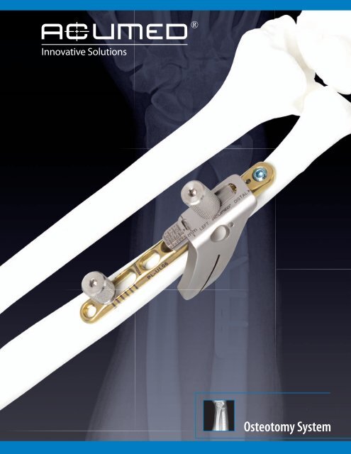
Osteotomy <strong>System</strong>
Osteotomy <strong>System</strong><br />
Since 1988, <strong>Acumed</strong> has been designing solutions for<br />
the demanding situations facing orthopaedic surgeons,<br />
hospitals and their patients. Our strategy has been to<br />
know the indication, design a solution to fit and deliver<br />
quality products and instrumentation.<br />
<strong>Acumed</strong>’s <strong>Ulna</strong>r <strong>Shortening</strong> Plate is designed to offer an<br />
anatomic, low-profile plate with built-in osteotomy reference<br />
lines and a simple cutting guide.<br />
The reference lines on the plate help facilitate the creation of<br />
the osteotomy, when a “free hand cut” is preferred.<br />
The plate offers locking screws which sit below the plate<br />
surface when fully seated. An offset screw compresses the<br />
osteotomy and an interfragmentary lag screw is placed<br />
through a scalloped slot in the center of the plate and angles<br />
across the osteotomy, helping to compress the osteotomy<br />
and maximize fixation.<br />
Designed in conjunction with William B. Geissler, M.D., the low-profile ulnar<br />
shortening plate is designed to keep the screw heads as low as possible,<br />
reducing soft tissue irritation. The interfragmentary lag screw has the option<br />
to be placed in two locations through a scalloped slot and compresses the<br />
osteotomy securely. The plate offers the option to lock up to three screws<br />
distally and one proximally.<br />
The advanced cutting guide offers precision and eliminates the need for a<br />
technically demanding cutting system. The adjustable guide reduces surgery<br />
time and allows a reduction of up to 10mm. An additional amount of<br />
shortening can be achieved after the initial 10mm resection is performed.<br />
Indications for an ulnar shortening osteotomy include:<br />
· <strong>Ulna</strong>r Impaction Syndrome due to<br />
ulnar-positive variance.<br />
· DRUJ incongruity due to shortening of the radius.<br />
· Traumatic and degenerative tears of the TFCC associated<br />
with positive ulnar variance.<br />
2
Osteotomy <strong>System</strong> Features<br />
Built-in Osteotomy Reference Guides<br />
Measurement reference lines on the side of the plate reference the amount<br />
of shortening desired. Each 40 o oblique laser line and spacing in between<br />
represents 2mm of shortening. The perpendicular lines near the measurement<br />
slot are spaced at 2mm giving a reference of shortening obtained from the<br />
osteotomy, reducing the use of x-ray to determine shortening.<br />
Simplified Osteotomy Guide<br />
The cutting guide allows you to make the adjustments needed to perform<br />
the first and second cuts without the need for numerous guides. The guide<br />
offers continuous adjustment from 1mm to 10mm to give you precisely the<br />
amount of resection desired.<br />
Advanced Instrumentation<br />
The reduction clamp utilizes a speed-lock wheel to maintain a hands free<br />
compression of the osteotomy. The multipurpose temporary reduction peg<br />
is partially threaded to ensure that the far cortex is not tapped prior to it<br />
being replaced by a screw. The peg first stabilizes the ulna to help maintain<br />
rotational alignment while creating the osteotomy prior to being used with<br />
the reduction clamp. This allows easy compression of the osteotomy and<br />
significantly simplifies the procedure.<br />
Measurement Slot<br />
Scalloped Lag Screw Slot<br />
.054" K-wire Hole<br />
Proximal Locking Hole<br />
Measurement Lines<br />
Compression Slot<br />
Osteotomy Measurement<br />
Reference Lines<br />
Three Distal Locking Holes<br />
3
Cutting Guide Assembly Features<br />
Locking Bolt Contains<br />
Hex for 2.5mm Driver<br />
Measurement Viewing Window<br />
Measurement Guide on Bottom Plate<br />
Osteotomy Viewing Window<br />
.054" K-wire Hole for<br />
Additional Stability<br />
Left and Right Specific<br />
Cutting Guides<br />
Cutting Slot Accepts up to<br />
.022" or .6mm Sagittal Blades<br />
Cutting Guide Assembly Instructions<br />
Step 1:<br />
Ensuring that the laser marked arrows are aligned, slide the bottom plate<br />
(80-0420) into the chosen cutting guide (80-0418 or 80-0419). Ensure that the<br />
bottom plate is completely engaged into the cutting guide.<br />
Note: The subsequent technique is for a volar approach with the cutting guide.<br />
If a medial approach is taken then the opposite cutting guide can be used.<br />
Be sure the cutting slot lines up with the angled measurement reference lines<br />
on the plate.<br />
Step 2:<br />
Slide the bottom plate distal enough so that the locking bolt (80-0421) can be<br />
inserted through both pieces.<br />
4
Saw Blade Specifications<br />
Two sterile saw blades have been designed for use with the Osteotomy<br />
<strong>System</strong>. Both contain identical dimensions, but different hub styles. The<br />
hub style L is compatible with most Linvatec/Hall® and Microaire® power<br />
instrumentation. The hub style S is compatible with most Stryker® power<br />
instrumentation.<br />
The use of any generic saw blade with the Osteotomy <strong>System</strong> must meet the<br />
specifications below and is to be considered the responsibility of the user.<br />
Blade specifications for use with Osteotomy <strong>System</strong>:<br />
Minimum Cutting Depth: 25mm<br />
Blade Thickness: Equal to or less than .6mm (.022")<br />
Hub Style L<br />
Hub Style S<br />
Osteotomy with Guide Surgical Technique by William B. Geissler, M.D.<br />
Step 1:<br />
Determine the amount of ulnar variance by preoperative x-rays. After exposing<br />
the volar side of the ulna, place the plate 3-5cm proximal to the distal end of the<br />
ulna. Secure the plate to the volar surface with one or more clamps. Make sure<br />
the proximal and distal orientation of the plate is correct, as noted by the laser<br />
marks on the plate.<br />
Step 2:<br />
Drill the most distal locking hole using the threaded drill guide(80-0384)<br />
and 2.8mm drill (80-0387) and insert the proper length 3.5mm light blue<br />
locking screw (COL-3XX0). In the proximal end of the measurement slot, drill<br />
bicortically and perpendicular to the plate and insert the temporary reduction<br />
peg (80-0422) with a 2.5mm hex driver.<br />
Option: You can pre-drill the two remaining distal locking holes in the same<br />
manner with the threaded drill guide but DO NOT INSERT SCREWS. You can also<br />
do this after the osteotomy has been achieved.<br />
5
Osteotomy with Guide<br />
Step 3:<br />
Remove the clamp and insert the pre-assembled cutting guide so that the<br />
locking bolt is inserted into the third most distal locking hole closest to the<br />
lasered Reference Lines. The cutting slot on the cutting guide will be aligned<br />
with the angled laser lines on the plate.<br />
Step 4:<br />
Set the cutting guide to the 1mm mark in the measurement window and firmly<br />
tighten the locking bolt (80-0421) with a 2.5mm hex driver.<br />
Step 5:<br />
For additional rotational stability, a plate tack (PL-TACK) may be inserted into the<br />
proximal locking hole and a .054" K-wire can be inserted into the K-wire hole in<br />
the distal end of the plate. A second .054" K-wire may be inserted through the<br />
cutting guide and into the bone for additional stability.<br />
Step 6:<br />
Insert the saw blade (80-0473-S for Linvatec/Hall style saws, 80-0499-S for<br />
Stryker saws) in the slot of the cutting guide and make first cut.<br />
Note: The cutting slot is .025" or .64mm wide. If a non-<strong>Acumed</strong> saw blade<br />
is being used, it must be thinner than the cutting slot and should allow for a<br />
minimum cutting depth of 25mm in order to pass through the guide and bone.<br />
If the kerf of the blade does not clear the slot, it may be inserted by sliding the<br />
blade through the open-end of the cutting slot.<br />
6
Surgical Technique by William B. Geissler, M.D.<br />
Step 7:<br />
Remove the K-wire inserted into the cutting guide and loosen the locking bolt<br />
just enough to slide the cutting guide to the number corresponding to the<br />
amount of shortening desired. Firmly retighten the locking bolt with the 2.5mm<br />
hex driver.<br />
Make sure that both sides of the ulna are re-aligned and re-insert the K-wire<br />
through the cutting guide into the bone. Make the 2nd cut.<br />
Note: The numbers on the bottom plate correspond to the desired amount of<br />
bone to be resected, i.e. the “4” signifies 4mm of resection.<br />
Step 8:<br />
Remove both K-wires, the cutting guide and plate tack. Slightly loosen (DO NOT<br />
REMOVE) the temporary reduction peg in the measurement slot and excise the<br />
bone wafer.<br />
Note: If the gap does not close, make sure there is no bone left in the<br />
osteotomy site near the plate. If this occurs the proximal and distal ends of the<br />
bone may be rotated under the plate to remove any bone blocking reduction.<br />
Step 9:<br />
Place a bone clamp over the distal portion of the ulna and plate to reduce<br />
the gap in between them. In the third most distal locking hole closest to the<br />
osteotomy, drill using the threaded drill guide (80-0384) and 2.8mm drill<br />
(80-0387) if pre-drilling was not preformed in STEP 2. Insert the proper length<br />
3.5mm locking screw or non-locking screw. Remove the bone clamp and place<br />
the threaded drill guide into the second distal locking hole.<br />
Step 10:<br />
Slightly loosen the reduction peg in the measurement slot. Place the reduction<br />
clamp (80-0423) around the reduction peg and threaded drill guide. Reduce<br />
the osteotomy gap with the reduction clamp and tighten the speed-lock wheel<br />
on the clamp to maintain reduction hands-free.<br />
7
Osteotomy with Guide cont...<br />
Step 11:<br />
While holding the compression, drill the proximal end of the compression slot<br />
with a 2.8mm drill, measure and insert a 3.5mm non-locking bicortical screw.<br />
Ensure that the desired amount of shortening has been achieved by x-ray.<br />
Figure 1 Figure 2<br />
Step 12:<br />
In the scalloped lag screw slot using a 3.5mm drill and the 3.5mm/2.8mm<br />
drill guide (PL-2196), drill a glide hole in the near cortex at an angle across<br />
the osteotomy site (Figure 1). Although the proximal or distal portion of<br />
the slot may be used depending on the osteotomy location and desired<br />
interfragmentary screw placement, the proximal slot is preferred. Next, place<br />
the 2.8mm end of the drill guide into the 3.5mm glide hole and use a 2.8mm<br />
drill to drill the far cortex (Figure 2).<br />
Note: If the angle of the drill is too shallow, the drill may collide with the<br />
adjacent screw in hole.<br />
Step 13:<br />
Measure and insert a non-locking 3.5mm screw into the scalloped lag screw<br />
slot. Remove the reduction clamp. Drill the second distal locking hole before<br />
removing the threaded drill guide. Measure and insert a locking screw into the<br />
remaining distal locking hole.<br />
Step 14:<br />
Remove the temporary reduction peg. Measure and replace with a 3.5mm<br />
non-locking screw. Drill, measure and insert a locking 3.5mm screw in the<br />
remaining proximal locking hole.<br />
8
Osteotomy w/o Guide Surgical Technique by William B. Geissler, M.D.<br />
Step 1:<br />
Determine the amount of ulnar variance by preoperative x-rays. After exposing<br />
the volar side of the ulna, place the plate 3-5cm proximal to the distal end of the<br />
ulna. Secure the plate to the volar surface with one or more clamps. Make sure<br />
the proximal and distal orientation of the plate is correct, as noted by the laser<br />
marks on the plate.<br />
Step 2:<br />
Drill the most distal locking hole using the threaded drill guide (80-0384)<br />
and 2.8mm drill (80-0387) and insert the proper length 3.5mm light blue<br />
locking screw (COL-3XX0). In the proximal end of the measurement slot, drill<br />
bicortically perpendicular to the plate and insert the temporary reduction peg<br />
(80-0422) with a 2.5mm hex driver.<br />
Option: You can pre-drill the two remaining distal locking holes in the same<br />
manner with the threaded drill guide but DO NOT INSERT SCREWS. You can also<br />
do this after the osteotomy has been achieved.<br />
Step 3:<br />
Using the 40° reference marks as a lines, create the osteotomy angled at least<br />
40° perpendicular to the plate. Start the osteotomy at the most distal laser<br />
mark. Create the osteotomy to the determined amount of shortening and excise<br />
the bone wafer. A .054" K-wire in the distal end of the plate and a plate tack in<br />
the proximal end may be used for additional stability.<br />
Note: Each 40° reference line and space is 2mm wide. Additionally, the kerf of<br />
the blade should be taken into consideration when creating the osteotomy.<br />
Step 4:<br />
Remove any K-wires and plate tacks. Make sure there is no bone left in the<br />
osteotomy site near the plate. If this occurs the proximal and distal ends of<br />
the bone may be rotated under the plate to remove any bone blocking the<br />
reduction.<br />
Place a bone clamp over the distal portion of the ulna and plate to reduce<br />
the gap in between them. In the third most distal locking hole closest to the<br />
osteotomy, drill using the threaded drill guide (80-0384) and 2.8mm drill<br />
(80-0387) if pre-drilling was not preformed in STEP 2. Insert a locking or<br />
bi-cortical non-locking screw.<br />
9
Osteotomy without Guide<br />
Step 5:<br />
Remove the bone clamp and place the threaded drill guide into the second<br />
distal locking hole. Slightly loosen the reduction peg in the measurement slot.<br />
Place the reduction clamp (80-0423) around the reduction peg and threaded<br />
drill guide. Reduce the osteotomy gap with the reduction clamp and tighten the<br />
speed-lock wheel on the clamp to maintain reduction hands-free.<br />
Step 6:<br />
While holding the compression, drill the proximal end of the compression slot<br />
with a 2.8mm drill, measure and insert a 3.5mm non-locking bicortical screw.<br />
Ensure that the desired amount of shortening has been achieved by x-ray.<br />
Figure 1 Figure 2<br />
Step 7:<br />
In scalloped slot using a 3.5mm drill and the 3.5mm/2.8mm drill guide<br />
(PL-2196), drill a glide hole in the near cortex at an angle across the osteotomy<br />
site (1). Next, place the 2.8mm end of the drill guide into the 3.5mm glide<br />
hole and use a 2.8mm drill to drill the far cortex (2). Measure and insert a nonlocking<br />
screw. The proximal or distal portion of the slot may be used depending<br />
on the osteotomy location and desired interfragmentary screw placement. The<br />
most proximal hole is preferred.<br />
Note: If the angle of the drill is too shallow, the drill may collide with the<br />
adjacent screw in hole.<br />
Step 8:<br />
Remove reduction clamp and drill the second distal locking hole before<br />
removing the threaded drill guide. Measure and insert a locking screw into the<br />
remaining distal locking hole. Remove the temporary reduction peg. Measure<br />
and replace with a 3.5mm non-locking screw. Drill, measure and insert a<br />
locking 3.5mm screw in the remaining proximal locking hole.<br />
10
Ordering Information<br />
<strong>Ulna</strong>r <strong>Shortening</strong> Osteotomy Plate<br />
<strong>Ulna</strong>r <strong>Shortening</strong> Plate<br />
3.5mm Locking Cortical Screws<br />
3.5mm x 8mm Locking Cortical Screw<br />
3.5mm x 10mm Locking Cortical Screw<br />
3.5mm x 12mm Locking Cortical Screw<br />
3.5mm x 14mm Locking Cortical Screw<br />
3.5mm x 16mm Locking Cortical Screw<br />
3.5mm x 18mm Locking Cortical Screw<br />
3.5mm Cortical Screws<br />
3.5mm x 10mm Cortical Screw<br />
3.5mm x 12mm Cortical Screw<br />
3.5mm x 14mm Cortical Screw<br />
3.5mm x 16mm Cortical Screw<br />
3.5mm x 18mm Cortical Screw<br />
3.5mm x 20mm Cortical Screw<br />
PL-UL06<br />
COL-3080<br />
COL-3100<br />
COL-3120<br />
COL-3140<br />
COL-3160<br />
COL-3180<br />
CO-3100<br />
CO-3120<br />
CO-3140<br />
CO-3160<br />
CO-3180<br />
CO-3200<br />
Instrumentation<br />
<strong>Ulna</strong>r <strong>Shortening</strong> Guide Left 80-0418<br />
<strong>Ulna</strong>r <strong>Shortening</strong> Guide Right 80-0419<br />
<strong>Ulna</strong>r <strong>Shortening</strong> Guide Bottom Plate 80-0420<br />
<strong>Ulna</strong>r <strong>Shortening</strong> Locking Bolt 80-0421<br />
<strong>Ulna</strong>r <strong>Shortening</strong> Reduction Peg 80-0422<br />
<strong>Ulna</strong>r <strong>Shortening</strong> Reduction Clamp 80-0423<br />
<strong>Ulna</strong>r <strong>Shortening</strong> Saw Blade - Hub Style L<br />
80-0473-S<br />
<strong>Ulna</strong>r <strong>Shortening</strong> Saw Blade - Hub Style S<br />
80-0499-S<br />
2.8mm Quick Release Drill 80-0387<br />
3.5mm x 5" Quick Release Drill<br />
MS-DC35<br />
2.8mm Locking Drill Guide 6-65mm 80-0384<br />
.054" x 6" Guide Wire WS-1406ST<br />
Tray<br />
Instrument Tray 80-0513<br />
Note: The <strong>Ulna</strong>r <strong>Shortening</strong> Osteotomy Plate can be used with the following <strong>Acumed</strong> systems: Universal Tray and Congruent Locking Elbow Plate.<br />
11
AcUMEDr<br />
5885 NW Cornelius Pass Road<br />
Hillsboro, OR 97124<br />
(888) 627-9957<br />
www.acumed.net<br />
Distributed by:<br />
HNW00-03-B<br />
Effective: 1/2010<br />
These materials contain information about products that may or may not be available in any particular<br />
country or may be available under different trademarks in different countries. The products may be<br />
approved or cleared by governmental regulatory organizations for sale or use with different indications<br />
or restrictions in different countries. Products may not be approved for use in all countries. Nothing<br />
contained on these materials should be construed as a promotion or solicitation for any product or for<br />
the use of any product in a particular way which is not authorized under the laws and regulations of<br />
the country where the reader is located. Specific questions physicians may have about the availability<br />
and use of the products described on these materials should be directed to their particular local sales<br />
representative. Specific questions patients may have about the use of the products described in these<br />
materials or the appropriateness for their own conditions should be directed to their own physician.