Fiat Ducato, Peugeot boxer, Citroen Jumper W21-760-2207
Fiat Ducato, Peugeot boxer, Citroen Jumper W21-760-2207
Fiat Ducato, Peugeot boxer, Citroen Jumper W21-760-2207

You also want an ePaper? Increase the reach of your titles
YUMPU automatically turns print PDFs into web optimized ePapers that Google loves.
1<br />
Unit 626 Kilshane Ave, North West Business Park, Ballycoolin, Dublin 15, Ireland<br />
Telephone: +353 1 8612 632 Fax: +353 1 8612 647 email:sales@driverite.iol.ie<br />
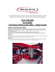
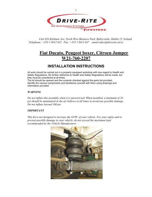
<strong>Fiat</strong> <strong>Ducato</strong>, <strong>Peugeot</strong> <strong>boxer</strong>, <strong>Citroen</strong> <strong>Jumper</strong><br />
<strong>W21</strong>-<strong>760</strong>-<strong>2207</strong><br />
INSTALLATION INSTRUCTIONS<br />
All work should be carried out in a properly equipped workshop with due regard to Health and<br />
Safety Regulations. No further reference to Health and Safety Regulations will be made, but<br />
they must be considered at all times.<br />
The kit should be opened and the contents checked against the parts list provided.<br />
Identify the various components and familiarise yourself with them using drawings and<br />
information provided.<br />
WARNING<br />
Do not inflate this assembly when it is unrestricted. When installed, a minimum of 10<br />
psi should be maintained in the air bellows at all times to avoid any possible damage.<br />
Do not inflate beyond 100 psi.<br />
IMPORTANT<br />
This kit is not designed to increase the GVW of your vehicle. For your safety and to<br />
prevent possible damage to your vehicle, do not exceed the maximum load<br />
recommended by the Vehicle Manufacturer.
2<br />
Parts List<br />
Description Quantity Description Quantity<br />
255 Air Spring 2 3/8-16 Flange Lock Nut 16<br />
Upper Bracket 2 3/8-16 Nylon Insert Nut 4<br />
Lower Bracket 2 Thermal Sleeve 2<br />
Bracket Strap 4 Cable Ties 16<br />
3/8 x 4 Poly Conv 2 Inflation Valve 1<br />
¼ Tubing 1 Metal Valve Cap 1<br />
3/8-16 x 6 Carriage Bolt 4 3/8-16UNC x 1 Hex Head 2<br />
M10 x 1.25 x 30 Hex Head 2 Elbow ¼ NPT to ¼ 2<br />
3/8 Lock Washer 8 ¼ Tee Piece 2<br />
3/8 Flat Washer 8<br />
Tubing and Parts Bracket set Air bellows
3<br />
1. PREPARATION:<br />
This suspension kit consists of all parts necessary to make a successful installation<br />
onto your Vehicle. All parts have been tested thoroughly. Please make sure you take<br />
all necessary safety precautions while fitting the kit.<br />
Note: you should first read these instructions carefully and then take all parts out of<br />
the box and pre-assemble them as far as possible before fitting them onto your<br />
vehicle.<br />
2. INSTALLATION<br />
Pre-assemble the air bellows as shown in the<br />
diagram on the left.<br />
Turn Air Fitting away from the two threaded studs.<br />
Place the two 10 x 150 bolts into the drilled holes on<br />
the lower bracket.<br />
Now bolt the base of the Air Bellow to the Lower<br />
Bracket using the 3/8-16 UNC hex head bolts<br />
Place one of the bracket straps under the lower<br />
bracket.<br />
Position the lower bracket in such a way that it<br />
stands parallel to the axle.<br />
Fasten the upper bracket to the framework using<br />
M10 x 30 bolts. Ensure the two flanges of the Upper<br />
Bracket are pushing away from the inside of the<br />
chassis as shown.
4<br />
Now take the pre-mounted Air Bellow/Bracket<br />
assembly, squeeze the Bags together (for ease of<br />
installation) and place each assembly in the centre of<br />
the axle.<br />
Bolt the Bellows to the Upper Bracket.<br />
The lower bracket now rests loosely on the axle. The<br />
actual attachment of the Lower Bracket is made with<br />
one additional Bracket Strap under the axle. Use the<br />
M10 lock nuts to fasten to axle.<br />
The position of the lower bracket must take place in<br />
such a way that it stands parallel to the axle. Place<br />
thermal sleeves over the air lines for protection.<br />
See Diagram.<br />
LSV - Model type 230<br />
After the assembly of the air bellows the LSV must<br />
be pre-loaded to increase the automatic Load<br />
Sensing. The original bracket must be exchanged by<br />
a longer bracket, which is included in the kit.<br />
The position of this bracket must be made in such a<br />
way that the distance between the upper and the<br />
lower points as shown amounts to 155 mm.<br />
See Photograph.<br />
LSV - Model type 244<br />
After the assembly of the Air Bellows the LSV must<br />
be pre-loaded to increase the automatic Load<br />
Sensing. The LSV clamp must be shifted 25mm<br />
toward the end of the rod as shown. In order to<br />
achieve this, the clamping screws (Fig 1) must be<br />
loosened and moved 25 mm towards rod end.
5<br />
TORQUE SETTINGS:<br />
(valid for the most usual mobile travel vehicles)<br />
Wheel bolts:<br />
Motor vehicle type: Wheel bolt Torque Settings<br />
<strong>Fiat</strong> <strong>Ducato</strong> 10/14 M14 x 1,5 160 Nm*²<br />
<strong>Fiat</strong> <strong>Ducato</strong> Maxi M16 x 1,5 180 Nm*²<br />
Mercedes Sprinter M14 x 1,5 180 Nm*²<br />
Heart pin (centering bolt) 8,8 * ³<br />
M 8<br />
M 10<br />
M 12<br />
25 Nm<br />
47 Nm<br />
86 Nm<br />
U – bolts:<br />
M 8<br />
M10<br />
M12<br />
M14<br />
25 Nm*³<br />
47 Nm*³<br />
118 Nm*³<br />
130 Nm*²<br />
Shock absorber:<br />
<strong>Fiat</strong> <strong>Ducato</strong><br />
160 Nm*²<br />
MB Sprinter 208-316 above 80 Nm below 70 Nm Screws<br />
8.8<br />
110 Nm Screws<br />
10.9<br />
MB Sprinter 408-416 above 140 Nm below 140 Nm<br />
* ² manufacturer data<br />
* ³ DIN 13, sheet 33 shank end screws quality 8,8, coefficient of friction m = 0,14
6<br />
TO AVOID LEAKAGES:<br />
The Suspension is inflated with compressed air via nylon hoses with an outside<br />
diameter of ¼ “. The connections are called “Plug-in” connections. This kind of<br />
connection allows you to attach the air hose without a tool. Here the hose must be put<br />
so far into the connection, until it locks. The correct fit can be examined by easily<br />
pulling on the hose. To recognize if it is the correct fit, during pulling the hose, the<br />
ring of the connection moves along with the hose. For the loosening of the hose<br />
connector the hose must be pushed toward the Plug in connection. Subsequently, with<br />
the ring held, the hose can be taken off.<br />
Note: With the pulling to check if the ring is too far pulled out, a leakage can occur!<br />
Note: In order to avoid slow air losses, the nylon hose should be cut straight with a<br />
sharp blade. Do not use a side cutter.<br />
Correctly cut. Straight cut off.<br />
Wrong.<br />
With frequent assembly use a nylontubing<br />
cutter.<br />
Air fittings:<br />
All air fittings are supplied with an<br />
easy “push to connect” fitting. To<br />
prevent leaking of air though, make<br />
sure that all tubing is cut squarely.<br />
These fittings make it easy to fit the<br />
air tubing and also to replace it if<br />
necessary.
7<br />
Brittle:<br />
Like all flexible rubber construction units, a certain natural embitterment occurs with<br />
the air bag. This procedure is natural, since the softeners in the plastic evaporate. If<br />
this occurs, then this leads to a cracking at the surface layer of the bag. If the auxiliary<br />
pneumatic spring is driven with a wrong operating pressure the embitterment is<br />
increased.<br />
Air loss/leakage:<br />
If within 24 hours the air pressure drops more than 0.2 bar a leak may be on the kit. If<br />
this is the case, then the complete kit must be sprayed with soap solution (leak<br />
detection spray). The leak is detected on the basis that bubbles appear. Most<br />
frequently the bubbles will be seen at the junction points after initial assembly. Mostly<br />
the reason for this is because of the non right-angled cut of hoses. As previously<br />
stated cutting off should take place by means of a straight cutter and not with the side<br />
cutter!<br />
Note:<br />
When driving on a ferry or when driving through a large bump on the road the<br />
possibility exists that at short notice the kit will be hit with a higher filling pressure<br />
(maximum 8 bar) than the vehicle is permitted to drive. Therefore, depending upon<br />
motor vehicle type and loading, the rear of the vehicle rises. This measure must be<br />
cancelled again however during normal travel, since this affects the braking action of<br />
your vehicle. If one drives on a high air pressure, then the brake delay of your vehicle<br />
can be reduced. Always guarantee that while driving the maximum operating pressure<br />
is kept in accordance with partial appraisals or registration papers.