INSTALLATION MANUAL - Fujitsu General - Portal Viewer
INSTALLATION MANUAL - Fujitsu General - Portal Viewer
INSTALLATION MANUAL - Fujitsu General - Portal Viewer

You also want an ePaper? Increase the reach of your titles
YUMPU automatically turns print PDFs into web optimized ePapers that Google loves.
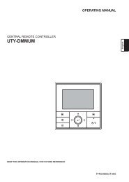
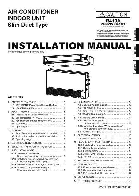
AIR CONDITIONER<br />
INDOOR UNIT<br />
Slim Duct Type<br />
Français<br />
Español<br />
English<br />
<strong>INSTALLATION</strong> <strong>MANUAL</strong><br />
For authorized service personnel only.<br />
Contents<br />
1. SAFETY PRECAUTIONS ............................................. 2<br />
1.1. IMPORTANT! Please Read Before Starting ........... 2<br />
1.2. Special precautions ................................................ 2<br />
2. ABOUT THE UNIT ........................................................ 3<br />
2.1. Precautions for using R410A refrigerant ................ 3<br />
2.2. Special tools for R410A .......................................... 3<br />
2.3. For authorized service personnel only. .................. 3<br />
2.4. Accessories ............................................................ 4<br />
2.5. Optional parts ......................................................... 5<br />
3. GENERAL ..................................................................... 5<br />
3.1. Type of copper pipe and insulation material ........... 5<br />
3.2. Additional materials required for installation.......... 5<br />
3.3. Operating range ..................................................... 5<br />
4. ELECTRICAL REQUIREMENT ..................................... 6<br />
5. SELECTING THE MOUNTING POSITION ................... 6<br />
6. <strong>INSTALLATION</strong> WORK ................................................. 7<br />
6.1A. Installation dimensions<br />
(Ceiling concealed type) ...................................... 7<br />
6.1B. Installation dimensions (Wall mounted type/<br />
Floor standing concealed type) ........................... 7<br />
6.2A. Installation the unit (Ceiling concealed type) ....... 7<br />
6.2B. Install the unit (Wall mounted type/<br />
Floor standing concealed type) ......................... 10<br />
7. PIPE <strong>INSTALLATION</strong> .................................................. 12<br />
7.1. Selecting the pipe material ................................... 12<br />
7.2. Pipe requirement .................................................. 12<br />
7.3. Flare connection (Pipe connection)...................... 12<br />
7.4. Installing heat insulation ....................................... 13<br />
8. INSTALLING DRAIN PIPES ........................................ 14<br />
8.1A. Installing drain pipes<br />
(Ceiling concealed type) .................................... 14<br />
8.1B. Installing drain pipes (Wall mounted type/<br />
Floor standing concealed type) ......................... 14<br />
8.2. Install the drain pipe ............................................. 15<br />
9. ELECTRICAL WIRING ................................................ 16<br />
9.1. INDOOR UNIT SIDE ............................................ 17<br />
10. REMOTE CONTROLLER SETTING ........................... 18<br />
10.1. Installing the remote controller ........................... 18<br />
10.2. Setting the dip switches ..................................... 19<br />
10.3. Function setting .................................................. 19<br />
10.4. Jumper wire setting ............................................ 22<br />
10.5. Test run .............................................................. 22<br />
11. SPECIAL <strong>INSTALLATION</strong> METHODS ......................... 23<br />
12. OPTIONAL PARTS ..................................................... 23<br />
12.1. External input and external output ..................... 23<br />
12.2. Remote sensor (Optional parts) ......................... 24<br />
12.3. IR Receiver Unit (Optional parts) ....................... 24<br />
13. ERROR CODES ......................................................... 25<br />
14. CUSTOMER GUIDANCE ............................................ 26<br />
PART NO. 9374342105-05
1<br />
1. SAFETY PRECAUTIONS<br />
1.1.IMPORTANT! Please Read Before Starting<br />
This air conditioning system meets strict safety and operating<br />
standards. As the installer or service person, it is an important<br />
part of your job to install or service the system so it operates<br />
safely and efficiently.<br />
For safe installation and trouble-free operation, you<br />
must:<br />
• Carefully read this instruction booklet before beginning.<br />
• Follow each installation or repair step exactly as shown.<br />
• Observe all local, state, and national electrical codes.<br />
• Pay close attention to all danger, warning, and caution notices<br />
given in this manual.<br />
This symbol refers to a hazard or unsafe practice<br />
which can result in severe personal injury<br />
WARNING:<br />
or death.<br />
This symbol refers to a hazard or unsafe practice<br />
which can result in personal injury and the<br />
CAUTION:<br />
potential for product or property damage.<br />
• Hazel alerting symbols<br />
<br />
<br />
Electrical<br />
Safety / alert<br />
If Necessary, Get Help<br />
These instructions are all you need for most installation sites<br />
and maintenance conditions. If you require help for a special<br />
problem, contact our sales/service outlet or your certified<br />
dealer for additional instructions.<br />
In Case of Improper Installation<br />
The manufacturer shall in no way be responsible for improper<br />
installation or maintenance service, including failure to follow<br />
the instructions in this document.<br />
1.2.Special precautions<br />
When Wiring<br />
ELECTRICAL SHOCK CAN CAUSE SEVERE PER-<br />
SONAL INJURY OR DEATH. ONLY A QUALIFIED,<br />
EXPERIENCED ELECTRICIAN SHOULD ATTEMPT<br />
TO WIRE THIS SYSTEM.<br />
• Do not supply power to the unit until all wiring and tubing<br />
are completed or reconnected and checked.<br />
• Highly dangerous electrical voltages are used in this system.<br />
Carefully refer to the wiring diagram and these instructions<br />
when wiring. Improper connections and inadequate<br />
grounding can cause accidental injury or death.<br />
• Ground the unit following local electrical codes.<br />
• Connect all wiring tightly. Loose wiring may cause overheating<br />
at connection points and a possible fire hazard.<br />
When Transporting<br />
Be careful when picking up and moving the indoor and outdoor<br />
units. Get a partner to help, and bend your knees when<br />
lifting to reduce strain on your back. Sharp edges or thin aluminum<br />
fins on the air conditioner can cut your fingers.<br />
When Installing...<br />
...In a Ceiling or Wall<br />
Make sure the ceiling/wall is strong enough to hold the unit’s<br />
weight. It may be necessary to construct a strong wood or<br />
metal frame to provide added support.<br />
...In a Room<br />
Properly insulate any tubing run inside a room to prevent<br />
“sweating” that can cause dripping and water damage to walls<br />
and floors.<br />
...In Moist or Uneven Locations<br />
Use a raised concrete pad or concrete blocks to provide a<br />
solid, level foundation for the outdoor unit. This prevents water<br />
damage and abnormal vibration.<br />
...In an Area with High Winds<br />
Securely anchor the outdoor unit down with bolts and a metal<br />
frame.<br />
...In a Snowy Area (for Heat Pump-type Systems)<br />
Install the outdoor unit on a raised platform that is higher than<br />
drifting snow.<br />
When Connecting Refrigerant Tubing<br />
• Keep all tubing runs as short as possible.<br />
• Use the flare method for connecting tubing.<br />
• Apply refrigerant lubricant to the matching surfaces of the<br />
flare and union tubes before connecting them, then tighten<br />
the nut with a torque wrench for a leak-free connection.<br />
• Check carefully for leaks before starting the test run.<br />
When Servicing<br />
• Turn the power OFF at the main circuit breaker panel before<br />
opening the unit to check or repair electrical parts and wiring.<br />
• Keep your fingers and clothing away from any moving parts.<br />
• Clean up the site after you finish, remembering to check<br />
that no metal scraps or bits of wiring have been left inside<br />
the unit being serviced.<br />
• After installation, explain correct operation to the customer,<br />
using the operating manual.<br />
DANGER<br />
Never touch electrical components immediately after the<br />
power supply has been turned off. Electrical shock may<br />
occur. After turning off the power, always wait 5 minutes<br />
or more before touching electrical components.<br />
En-2
1<br />
1<br />
2. ABOUT THE UNIT<br />
2.1. Precautions for using R410A refrigerant<br />
The basic installation work procedures are the same as<br />
conventional refrigerant (R22) models.<br />
However, pay careful attention to the following points:<br />
• Since the working pressure is 1.6 times higher than that of<br />
conventional refrigerant (R22) models, some of the piping and<br />
installation and service tools are special. (See the table below.)<br />
Especially, when replacing a conventional refrigerant<br />
(R22) model with a new refrigerant R410A model, always<br />
replace the conventional piping and flare nuts with the<br />
R410A piping and flare nuts.<br />
• Models that use refrigerant R410A have a different charging<br />
port thread diameter to prevent erroneous charging with<br />
conventional refrigerant (R22) and for safety. Therefore,<br />
check beforehand. [The charging port thread diameter for<br />
R410A is 1/2 inch.]<br />
• Be more careful that foreign matter (oil, water, etc.) does<br />
not enter the piping than with refrigerant (R22) models.<br />
Also, when storing the piping, securely seal the opening<br />
by pinching, taping, etc.<br />
• When charging the refrigerant, take into account the slight<br />
change in the composition of the gas and liquid phases, and<br />
always charge from the liquid phase side whose composition<br />
is stable.<br />
2.2. Special tools for R410A<br />
Tool name<br />
Gauge manifold<br />
Charge hose<br />
Vacuum pump<br />
Contents of change<br />
Pressure is high and cannot be<br />
measured with a conventional<br />
gauge. To prevent erroneous<br />
mixing of other refrigerants, the<br />
diameter of each port has been<br />
changed.<br />
It is recommended the gauge with<br />
seals 30 in. Hg to 768 psi for high<br />
pressure.<br />
30 in. Hg to 551 psi for low pressure.<br />
To increase pressure resistance,<br />
the hose material and base size<br />
were changed.<br />
A conventional vacuum pump can<br />
be used by installing a vacuum<br />
pump adapter.<br />
Copper pipes<br />
It is necessary to use seamless copper pipes and it is desirable that<br />
the amount of residual oil is less than 0.0014 oz/10 m (33 ft). Do<br />
not use copper pipes having a collapsed, deformed or discolored<br />
portion (especially on the interior surface). Otherwise, the expansion<br />
value or capillary tube may become blocked with contaminants.<br />
As an air conditioner using R410A incurs pressure higher than<br />
when using R22, it is necessary to choose adequate materials.<br />
Thicknesses of copper pipes used with R410A are as shown<br />
in the table. Never use copper pipes thinner than that in the<br />
table even when it is available on the market.<br />
WARNING<br />
Do not use the existing (for R22) piping and flare nuts.<br />
• If the existing materials are used, the pressure inside<br />
the refrigerant cycle will rise and cause failure, injury,<br />
etc. (Use the special R410A materials.)<br />
When installing and relocating the air conditioner,<br />
do not mix gases other than the specified refrigerant<br />
(R410A) to enter the refrigerant cycle.<br />
• If air or other gas enters the refrigerant cycle, the<br />
pressure inside the cycle will rise to an abnormally<br />
high value and cause failure, injury, etc.<br />
2.3. For authorized service personnel only.<br />
WARNING<br />
For the air conditioner to operate satisfactorily, install it as<br />
outlined in this installation manual.<br />
Connect the indoor unit and outdoor unit with the air<br />
conditioner piping and cords available from your local<br />
distributor. This installation manual describes the correct<br />
connections using the installation set available from your local<br />
distributor.<br />
Installation work must be performed in accordance with<br />
national wiring standards by authorized personnel only.<br />
Do not turn on the power until all installation work is complete.<br />
CAUTION<br />
This installation manual describes how to install the indoor<br />
unit only. To install the outdoor unit, refer to the installation<br />
manual included with the outdoor unit.<br />
• Be careful not to scratch the air conditioner when handling<br />
it.<br />
• After installation, explain correct operation to the customer,<br />
using the operating manual.<br />
Gas leakage detector<br />
Special gas leakage detector for<br />
HFC refrigerant R410A.<br />
En-3
2.4. Accessories<br />
WARNING<br />
For installation purposes, be sure to use the parts supplied by<br />
the manufacturer or other prescribed parts.<br />
The use of non-prescribed parts can cause serious accidents<br />
such as the unit to fall, water leakage, electric shock, or fire.<br />
The following installation parts are furnished. Use them as<br />
required.<br />
Keep the Installation Manual in a safe place and do not<br />
discard any other accessories until the installation work has<br />
been completed.<br />
Name and Shape Q’ty Application<br />
Filter (Small)<br />
Filter (Big)<br />
2<br />
(AR9/<br />
12/24)<br />
2<br />
(AR18)<br />
1<br />
(AR24)<br />
Do not discard any accessories needed for installation until<br />
the installation work has been completed.<br />
Drain hose<br />
1<br />
For installing drain pipe<br />
3/4 in. (O.D. 1-1/16 in.)<br />
Name and Shape Q’ty Application<br />
Operating Manual<br />
Hose band<br />
For installing drain hose<br />
1<br />
1<br />
Installation Manual<br />
(This book)<br />
Drain hose insulation B<br />
Insulates the drain hose<br />
1<br />
1<br />
Installation<br />
template<br />
For positioning the indoor<br />
unit<br />
Wired Remote<br />
Controller<br />
1<br />
1<br />
Remote Controller<br />
Cable<br />
1<br />
For connecting the<br />
remote controller<br />
Washer<br />
8<br />
For installing indoor unit<br />
Tapping screw<br />
(M4 × 16 mm)<br />
2<br />
For installing the remote<br />
controller<br />
Coupler<br />
heat insulation<br />
(Large) 1<br />
For indoor side pipe joint<br />
(Large pipe)<br />
Coupler<br />
heat insulation<br />
(Small) 1<br />
For indoor side pipe joint<br />
(Small pipe)<br />
Binder<br />
Medium<br />
3<br />
For power supply and<br />
remote control cable<br />
binding.<br />
Large<br />
4<br />
For fixing the coupler<br />
heat insulation.<br />
En-4
]1<br />
]1<br />
]1<br />
2.5. Optional parts<br />
Description Model No. Application<br />
Wireless Remote<br />
Controller<br />
Wired Remote<br />
Controller<br />
Simple Remote<br />
Controller<br />
UTY-LNHUM<br />
UTY-RNNUM<br />
UTY-RSNUM<br />
IR Receiver Unit UTY-LRHUM<br />
Remote sensor unit<br />
UTY-XSZX<br />
External control set UTD-ECS5A<br />
3. GENERAL<br />
For air conditioner<br />
operation<br />
For air conditioner<br />
operation<br />
For air conditioner<br />
operation<br />
For the wireless<br />
remote controller<br />
Room temperature<br />
sensor<br />
For control input/<br />
output port<br />
This <strong>INSTALLATION</strong> <strong>MANUAL</strong> briefly outlines where and how<br />
to install the air conditioning system. Please read over the<br />
entire set of instructions for the indoor and outdoor units and<br />
make sure all accessory parts listed are with the system before<br />
beginning.<br />
3.1. Type of copper pipe and insulation material<br />
Copper tubing for connecting the outdoor unit to the indoor<br />
unit and insulation material is available for purchase locally.<br />
When you purchase them, please specify the following.<br />
• Deoxidized annealed copper pipe for refrigerant piping as:<br />
CAUTION<br />
Refer to the Installation Manual for the outdoor unit<br />
for description of allowable pipe length and height<br />
difference.<br />
CAUTION<br />
Install heat insulation around both the gas and liquid<br />
pipes. Failure to do so may cause water leaks.<br />
Use heat insulation with heat resistance above<br />
248 °F. (Reverse cycle model only)<br />
In addition, if the humidity level at the installation<br />
location of the refrigerant piping is expected to<br />
exceed 70%, install heat insulation around the<br />
refrigerant piping. If the expected humidity level is<br />
70-80%, use heat insulation that is 15 mm (19/32 in.)<br />
or thicker and if the expected humidity exceeds 80%,<br />
use heat insulation that is 20 mm (25/32 in.) or thicker.<br />
If heat insulation is used that is not as thick as<br />
specified, condensation may form on the surface of<br />
the insulation. In addition, use heat insulation with<br />
heat conductivity of 0.045 W/(m•K) or less (at 68 °F).<br />
3.2. Additional materials required for installation<br />
A. Refrigeration (armored) tape<br />
B. Insulated staples or clamps for connecting wire<br />
(See your local electrical codes.)<br />
C. Putty<br />
D. Refrigeration lubricant<br />
E. Clamps or saddles to secure refrigerant piping<br />
3.3. Operating range<br />
Cooling/Dry Mode Heating Mode<br />
Temperature About 64 to 90 °F About 60 to 88 °F<br />
Humidity About 80% or less ─<br />
Diameter<br />
MODEL<br />
Liquid pipe Gas pipe<br />
AR9/12 model 6.35 mm (1/4 in.) 9.52 mm (3/8 in.)<br />
AR18 model 6.35 mm (1/4 in.) 12.70 mm (1/2 in.)<br />
AR24 model 6.35 mm (1/4 in.) 15.88 mm (5/8 in.)<br />
• Use pipe with water-resistant heat insulation.<br />
En-5
4. ELECTRICAL REQUIREMENT<br />
Always make the air conditioner power supply a special<br />
branch circuit and provide a special switch and receptacle. Do<br />
not extend the power cable.<br />
WARNING<br />
Refer to local codes for acceptable cable type.<br />
Cable Cable size Remarks<br />
Connection cable<br />
14 AWG<br />
3 cable + Ground<br />
1Φ 208/230 V<br />
Max. Cable Length: Limit voltage drop to less than 2%. Increase<br />
cable gauge if voltage drop is 2% or more.<br />
5. SELECTING THE MOUNTING POSITION<br />
Correct initial installation location is important because it is<br />
difficult to move unit after it is installed.<br />
WARNING<br />
Select installation locations that can properly support the<br />
weight of the indoor. Install the units securely so that they do<br />
not topple or fall.<br />
CAUTION<br />
Do not install the unit in the following areas:<br />
• Area with high salt content, such as at the seaside.<br />
It will deteriorate metal parts, causing the parts to fail or the<br />
unit to leak water.<br />
• Area filled with mineral oil or containing a large amount of<br />
splashed oil or steam, such as a kitchen.<br />
It will deteriorate plastic parts, causing the parts to fail or<br />
the unit to leak water.<br />
• Area that generates substances that adversely affect the<br />
equipment, such as sulfuric gas, chlorine gas, acid, or<br />
alkali.<br />
It will cause the copper pipes and brazed joints to corrode,<br />
which can cause refrigerant leakage.<br />
• Area that can cause combustible gas to leak, contains<br />
suspended carbon fibers or flammable dust, or volatile<br />
inflammables such as paint thinner or gasoline.<br />
If gas leaks and settles around the unit, it can cause a fire.<br />
• Area where animals may urinate on the unit or ammonia<br />
may be generated.<br />
CAUTION<br />
Do not install the unit near a source of heat, steam, or<br />
flammable gas.<br />
Install the unit where drainage does not cause any trouble.<br />
Install the indoor unit, outdoor unit, power supply cable,<br />
and remote control cable at least 40 in. (1 m) away from a<br />
television or radio receivers. The purpose of this is to prevent<br />
TV reception interference or radio noise.<br />
(Even if they are installed more than 40 in. (1 m) apart, you<br />
could still receive noise under some signal conditions.)<br />
If children under 10 years old may approach the unit, take<br />
preventive measures so that they cannot reach the unit.<br />
• Decide the mounting position with the customer as<br />
follows:<br />
(1) Install the indoor unit on a place having a sufficient strength<br />
so that it withstands against the weight of the indoor unit.<br />
(2) The inlet and outlet ports should not be obstructed; the air<br />
should be able to blow all over the room.<br />
(3) Leave the space required to service the air conditioner.<br />
(4) A place from where the air can be distributed evenly<br />
throughout the room by the unit.<br />
(5) Install the unit where connection to the outdoor unit is easy.<br />
(6) Install the unit where the connection pipe can be easily<br />
installed.<br />
(7) Install the unit where the drain pipe can be easily installed.<br />
(8) Install the unit where noise and vibrations are not amplified.<br />
(9) Take servicing, etc., into consideration and leave the spaces.<br />
Also install the unit where the filter can be removed.<br />
Do not use the unit for special purposes, such as storing<br />
food, raising animals, growing plants, or preserving precision<br />
devices or art objects.<br />
It can degrade the quality of the preserved or stored objects.<br />
Do not install where there is the danger of combustible gas<br />
leakage.<br />
En-6
6. <strong>INSTALLATION</strong> WORK<br />
6.1A. Installation dimensions<br />
(Ceiling concealed type)<br />
Provide a service access for inspection purposes.<br />
Do not place any wiring or illumination in the service space,<br />
as they will impede service.<br />
Installation Dimensions<br />
Strong and durable ceiling<br />
unit: mm (in.)<br />
6.1B. Installation dimensions (Wall mounted<br />
type/Floor standing concealed type)<br />
The wall mounted type/floor standing concealed type<br />
requires a temperature correction setting. Perform this in<br />
“10.3. Function setting”.<br />
Left side<br />
10 (13/32)<br />
or less<br />
10 (13/32)<br />
or less Right side<br />
(PIPE side)<br />
unit: mm (in.)<br />
Left<br />
side<br />
100 (3-15/16)<br />
or more<br />
Indoor unit<br />
300 (11-13/16)<br />
or more<br />
300 (11-13/16) or more<br />
Right<br />
side<br />
150 (5-29/32)<br />
or more<br />
100 (3-15/16)<br />
or more<br />
Strong and<br />
durable floor<br />
300 (11-13/16)<br />
or more<br />
Grill<br />
Inlet air<br />
Strong and<br />
durable floor<br />
Right side<br />
(PIPE side)<br />
20 (25/32)<br />
or more<br />
20 (25/32)<br />
or more<br />
150 (5-29/32)<br />
or more<br />
Duct<br />
240 (9-7/16) or<br />
more<br />
20 (25/32) or more<br />
20 (25/32) or more<br />
Service access<br />
Ceiling<br />
2500 (8 ft 3 in.) or<br />
more<br />
(When no ceiling)<br />
Floor<br />
Adjust the wind direction in the room depending on the<br />
shape of blow out opening.<br />
Service access<br />
300 (11-13/16)<br />
or more<br />
Unit<br />
Service space<br />
100 (3-15/16)<br />
or more<br />
300 (11-13/16)<br />
or more<br />
Control<br />
box<br />
Left side<br />
150 (5-29/32)<br />
or more<br />
100 (3-15/16)<br />
or more<br />
Strong and<br />
durable floor<br />
300 (11-13/16)<br />
or more<br />
Grill<br />
Inlet air<br />
Strong and<br />
durable floor<br />
6.2A. Installation the unit<br />
(Ceiling concealed type)<br />
WARNING<br />
20 (25/32)<br />
or more<br />
20 (25/32)<br />
or more<br />
Install the air conditioner in a location which can withstand a<br />
load do at least 5 times the weight of the main unit and which<br />
will not amplify sound or vibration. If the installation location is<br />
not strong enough, the indoor unit may fall and cause injuries.<br />
If the job is done with the panel frame only, there is a risk that<br />
the unit will come loose. Please take care.<br />
150 (5-29/32)<br />
or more<br />
6.2A.1. UNIT <strong>INSTALLATION</strong> EXAMPLE (CEILING<br />
CONCEALED TYPE)<br />
Connect the locally purchased duct.<br />
(1) Inlet side<br />
• Connect the duct to the locally purchased inlet flange.<br />
• Connect the flange to the body with the locally purchased<br />
tapping screws.<br />
• Wind the inlet flange connecting to the duct with the<br />
aluminum tape etc. to avoid the air discharge.<br />
CAUTION<br />
When the duct is connected to inlet side, remove contained<br />
filter and surely attach locally purchased filter at inlet opening.<br />
(2) Outlet side<br />
• Connect the duct with adjusting inside of outlet flange.<br />
• Wind the outlet flange connecting to the duct with the<br />
aluminum tape etc. to avoid the air discharge.<br />
• Insulate the duct to avoid the dew condensation.<br />
En-7
CAUTION<br />
Check that duct work does not exceed the range of external<br />
static pressure of equipment.<br />
Make sure to insulate ducts to avoid condensation.<br />
Make sure to insulate between ducts and walls if metal ducts<br />
are used.<br />
Please explain handling and washing methods of locally<br />
purchased materials to the customer.<br />
To prevent people from touching the parts inside the unit, be<br />
sure to install grilles on the inlet and outlet ports. The grilles<br />
must be designed in such a way that cannot be removed<br />
without tools.<br />
When connecting the duct to the outlet port of the indoor unit,<br />
be sure to insulate the outlet port and the installation screws<br />
to prevent water from leaking around the port.<br />
AR9/12/18 Model<br />
• Set the static pressure outside the unit to 0.36 in. WG or<br />
less (the allowable range is between 0 and 0.36 in. WG).<br />
AR24 Model<br />
• Set the static pressure outside the unit to 0.2 in. WG or<br />
less (the allowable range is between 0 and 0.2 in. WG).<br />
Replace the cover as follows.<br />
• Remove the screws, and then remove cover and fan<br />
guard.<br />
• Install the cover with the screws as shown in the illustration<br />
below.<br />
Model<br />
Screw<br />
M5<br />
AR9/12 9<br />
AR18 11<br />
AR24 13<br />
Side Inlet - Side Outlet<br />
Air<br />
Insulation material (Field supply)<br />
Aluminum tape<br />
Flange (Field supply)<br />
Duct<br />
(Field supply)<br />
Intake grille<br />
(Field supply)<br />
Side Inlet - Side Outlet (Duct)<br />
Air<br />
Insulation material (Field supply)<br />
Aluminum tape<br />
Flange (Field supply)<br />
Duct<br />
(Field supply)<br />
Bottom Inlet - Side Outlet<br />
Duct (Field supply)<br />
Air<br />
Intake grille<br />
(Field supply)<br />
Air<br />
Flange (Field supply)<br />
Aluminum tape<br />
Tapping screw for<br />
flange connection<br />
(M5 x 10 mm /<br />
Field supply)<br />
Air<br />
screw (M5)<br />
Cover<br />
Intake grille (Field supply)<br />
Outlet side<br />
Air<br />
unit: mm (in.)<br />
25 31/32<br />
Fan guard<br />
Inlet side<br />
31/32<br />
7-25/32<br />
unit: mm (in.)<br />
AR9/12 AR18 AR24<br />
A 650 (25-19/32) 850 (33-15/32) 1050 (41-11/32)<br />
B<br />
P200 (7-7/8) × 2 P200 (7-7/8) × 3 P200 (7-7/8) × 4<br />
= 400 (15-3/4) = 600 (23-5/8) = 800 (31-1/2)<br />
En-8
6.2A.2. INSTALL THE FILTERS<br />
• Install the filters to the unit.<br />
6.2A.4. FIX THE UNIT<br />
(1) Hang the unit<br />
Hanger bolt<br />
Hanger<br />
Nut A<br />
(Field supply)<br />
Washer<br />
(Accessories)<br />
Nut B<br />
(Field supply)<br />
AR9/12/18: 2 filters<br />
AR24: 3 filters<br />
Filter (Accessories)<br />
Nut A<br />
(Field supply)<br />
Washer<br />
(Accessories)<br />
Hanger bolt<br />
Hanger<br />
Unit<br />
Unit<br />
Filter<br />
Nut B<br />
(Field supply)<br />
20 mm<br />
(25/32 in.)<br />
length<br />
6.2A.3. DRILLING HOLES FOR BOLTS AND IN-<br />
STALLING THE BOLTS<br />
• Using the installation template, drill holes for bolts (4 holes).<br />
Installation template<br />
Drilling position<br />
for bolts<br />
Cover<br />
*: It might become difficult to open and shut the Cover /control<br />
box cover when the length exceeds 20 mm (25/32 in.).<br />
(2) Leveling<br />
Base horizontal direction leveling on top of the unit.<br />
Ceiling<br />
Level<br />
Air<br />
A<br />
377 mm<br />
(14-27/32)<br />
OK<br />
10mm (13/32 in.) or less<br />
NO GOOD<br />
unit: mm (in.)<br />
AR9/12 AR18 AR24<br />
A 734 (28-29/32) 934 (36-25/32) 1134 (44-21/32)<br />
En-9
Air<br />
Level<br />
CAUTION<br />
Leave a space of 100 mm (3-15/16 in.) or more between the<br />
inlet port and the ceiling.<br />
Fasten the unit securely with Special nuts A and B.<br />
6.2B. Install the unit (Wall mounted type/<br />
Floor standing concealed type)<br />
WARNING<br />
Install the air conditioner in a location which can withstand a<br />
load do at least 5 times the weight of the main unit and which<br />
will not amplify sound or vibration. If the installation location is<br />
not strong enough, the indoor unit may fall and cause injuries.<br />
If the job is done with the panel frame only, there is a risk that<br />
the unit will come loose. Please take care.<br />
6.2B.1. UNIT <strong>INSTALLATION</strong> EXAMPLE<br />
(Wall mounted type/Floor standing concealed<br />
type)<br />
Connect the locally purchased duct.<br />
(1) Inlet side<br />
• Connect the duct to the locally purchased inlet flange.<br />
• Connect the flange to the body with the locally purchased<br />
tapping screws.<br />
• Wind the inlet flange connecting to the duct with aluminum<br />
tape etc. to avoid the air discharge.<br />
CAUTION<br />
When duct is connected to inlet side, remove filter provided<br />
with unit and attach locally purchased filter at return air grille<br />
or in return duct.<br />
(2) Outlet side<br />
• Connect the duct to outlet flange.<br />
• Wind the outlet flange connecting to the duct with<br />
aluminum tape etc. to avoid the air discharge.<br />
• Insulate the duct to avoid condensation.<br />
CAUTION<br />
Check that duct work does not exceed the range of external<br />
static pressure of equipment.<br />
Make sure to insulate ducts to avoid condensation.<br />
Make sure to insulate between ducts and walls if metal ducts<br />
are used.<br />
Please explain handling and washing methods of locally<br />
purchased materials to the customer.<br />
To prevent people from touching the parts inside the unit, be<br />
sure to install grilles on the inlet and outlet ports. The grilles<br />
must be designed in such a way that cannot be removed<br />
without tools.<br />
When connecting the duct to the outlet port of the indoor unit,<br />
be sure to insulate the outlet port and the installation screws<br />
to prevent water from leaking around the port.<br />
AR9/12/18 Model<br />
• Set the static pressure outside the unit to 0.36 in. WG or less<br />
(the allowable range is between 0 and 0.36 in. WG).<br />
AR24 Model<br />
• Set the static pressure outside the unit to 0.2 in. WG or less<br />
(the allowable range is between 0 and 0.2 in. WG).<br />
• Remove the screws, and then remove cover and fan<br />
guard.<br />
• Install the cover with the screws as shown in the illustration<br />
below.<br />
Model<br />
Screw<br />
M5<br />
AR9/12 9<br />
AR18 11<br />
AR24 13<br />
En-10
6.2B.2. INSTALL THE FILTER<br />
• Install the filters (Accessories) to the unit.<br />
6.2B.3. INSTALLING THE UNIT<br />
• To prevent overturning, attach the unit to the floor or the<br />
wall.<br />
• To avoid vibration of the unit, install vibration isolation pad<br />
between the unit and the floor or the wall.<br />
Leveling<br />
Level unit before attaching to floor or wall.<br />
Level<br />
Filter<br />
AR9/12/18: 2 filters<br />
AR24: 3 filters<br />
Unit<br />
Filter<br />
10 mm or less<br />
(13/32 in.)<br />
OK<br />
NO GOOD<br />
Level<br />
Replace drain cap<br />
CAUTION<br />
• Set “10.4. Jumper wire setting of Drainage function setting<br />
(JM1)”.<br />
• Drain pump cannot be used if it is installed in wall mounted<br />
type/floor standing concealed type.<br />
10 mm or less<br />
(13/32 in.)<br />
OK<br />
NO GOOD<br />
CAUTION<br />
Fasten the unit securely with Special nuts A and B.<br />
En-11
7. PIPE <strong>INSTALLATION</strong><br />
CAUTION<br />
Be careful that foreign matter (oil, water, etc.) does not enter<br />
the piping with refrigerant R410A models. Also, when storing<br />
the piping, securely seal the openings by pinching, taping,<br />
etc.<br />
While brazing the pipes, be sure to purge with dry nitrogen<br />
gas.<br />
7.1. Selecting the pipe material<br />
Do not use existing pipes.<br />
CAUTION<br />
Use pipes that have clean external and internal sides without<br />
any contamination which may cause trouble during use, such<br />
as sulfur, oxide, dust, cutting waste, oil, or water.<br />
It is necessary to use seamless copper pipes.<br />
Material : Phosphor deoxidized seamless copper pipes<br />
It is desirable that the amount of residual oil is less than<br />
40 mg/10 m (33 ft).<br />
Do not use copper pipes that have a collapsed, deformed,<br />
or discolored portion (especially on the interior surface).<br />
Otherwise, the expansion valve or capillary tube may become<br />
blocked with contaminants.<br />
Improper pipe selection will degrade performance. As an air<br />
conditioner using R410A incurs pressure higher than when<br />
using conventional refrigerant, it is necessary to choose<br />
adequate materials.<br />
• Thicknesses of copper pipes used with R410A are as<br />
shown in the table.<br />
• Never use copper pipes thinner than those indicated in the<br />
table even if they are available on the market.<br />
Thicknesses of Annealed Copper Pipes (R410A)<br />
Pipe outside diameter [mm (in.)] Thickness [mm (in.)]<br />
6.35 (1/4) 0.80 (0.032)<br />
9.52 (3/8) 0.80 (0.032)<br />
12.70 (1/2) 0.80 (0.032)<br />
15.88 (5/8) 1.00 (0.039)<br />
19.05 (3/4) 1.20 (0.047)<br />
7.2. Pipe requirement<br />
CAUTION<br />
Refer to the Installation Manual of the outdoor unit for<br />
description of the length of connecting pipe or for difference<br />
of its elevation.<br />
• Use pipe with water-resistant heat insulation.<br />
CAUTION<br />
Install heat insulation around both the gas and liquid pipes.<br />
Failure to do so may cause water leaks.<br />
Use heat insulation with heat resistance above 248°F.<br />
(Reverse cycle model only)<br />
In addition, if the humidity level at the installation location<br />
of the refrigerant piping is expected to exceed 70 %,<br />
install heat insulation around the refrigerant piping. If the<br />
expected humidity level is 70-80 %, use heat insulation<br />
that is 15mm(19/32 in.) or thicker and if the expected<br />
humidity exceeds 80 %, use heat insulation that is<br />
20mm(25/32 in.) or thicker. If heat insulation is used<br />
that is not as thick as specified, condensation may form<br />
on the surface of the insulation. In addition, use heat<br />
insulation with heat conductivity of 0.045 W/(m·K) or less<br />
(at 68°F).<br />
7.3. Flare connection (Pipe connection)<br />
WARNING<br />
Tighten the flare nuts with a torque wrench using the<br />
specified tightening method. Otherwise, the flare nuts could<br />
break after a prolonged period, causing refrigerant to leak<br />
and generate a hazardous gas if the refrigerant comes into<br />
contact with a flame.<br />
7.3.1. Flaring<br />
• Use special pipe cutter and flare tool exclusive for R410A.<br />
(1) Cut the connection pipe to the necessary length with a<br />
pipe cutter.<br />
(2) Hold the pipe downward so that cuttings will not enter the<br />
pipe and remove any burrs.<br />
(3) Insert the flare nut (always use the flare nut attached to<br />
the indoor and outdoor units respectively) onto the pipe<br />
and perform the flare processing with a flare tool. Use<br />
the special R410A flare tool, or the conventional flare<br />
tool. Leakage of refrigerant may result if other flare nuts<br />
are used.<br />
(4) Protect the pipes by pinching them or with tape to<br />
prevent dust, dirt, or water from entering the pipes.<br />
En-12
Die<br />
A<br />
Pipe outside<br />
diameter<br />
[mm (in.)]<br />
Pipe<br />
Check if [L] is flared uniformly<br />
and is not cracked or scratched.<br />
Dimension A<br />
[mm (in.)] Dimension B-0.4<br />
0<br />
Flare tool for R410A, [mm (in.)]<br />
clutch type<br />
6.35 (1/4)<br />
9.1 (11/32)<br />
9.52 (3/8) 13.2 (17/32)<br />
0 to 0.5<br />
12.70 (1/2) 16.6 (21/32)<br />
(0 to 0.020)<br />
15.88 (5/8) 19.7 (25/32)<br />
19.05 (3/4) 24.0 (15/16)<br />
When using conventional flare tools to flare R410A pipes,<br />
the dimension A should be approximately 0.5 mm (0.020 in.)<br />
more than indicated in the table (for flaring with R410A flare<br />
tools) to achieve the specified flaring. Use a thickness gauge<br />
to measure the dimension A.<br />
Width across<br />
flats<br />
7.3.2. Bending pipes<br />
Pipe outside<br />
diameter [mm (in.)]<br />
Width across flats<br />
of Flare nut [mm (in.)]<br />
6.35 (1/4) 17 (21/32)<br />
9.52 (3/8) 22 (7/8)<br />
12.70 (1/2) 26 (1-1/32)<br />
15.88 (5/8) 29 (1-5/32)<br />
19.05 (3/4) 36 (1-13/32)<br />
• If pipes are shaped by hand, be careful not to collapse<br />
them.<br />
• Do not bend the pipes in an angle more than 90°.<br />
• When pipes are repeatedly bend or stretched, the material<br />
will harden, making it difficult to bend or stretch them any<br />
more.<br />
• Do not bend or stretch the pipes more than 3 times.<br />
CAUTION<br />
To prevent breaking of the pipe, avoid sharp bends.<br />
If the pipe is bent repeatedly at the same place, it will break.<br />
7.3.3. Pipe connection<br />
CAUTION<br />
Be sure to install the pipe against the port on the indoor unit<br />
correctly. If the centering is improper, the flare nut cannot<br />
tighten smoothly. If the flare nut is forced to turn, the threads<br />
will be damaged.<br />
Do not remove the flare nut from the indoor unit pipe until<br />
immediately before connecting the connection pipe.<br />
Hold the torque wrench at its grip, keeping it at a right angle<br />
with the pipe, in order to tighten the flare nut correctly.<br />
Tighten the flare nuts with a torque wrench using the specified<br />
tightening method. Otherwise, the flare nuts could break after<br />
a prolonged period, causing refrigerant to leak and generate<br />
a hazardous gas if the refrigerant comes into contact with a<br />
flame.<br />
CAUTION<br />
Connect the piping so that the control box cover can easily be<br />
removed for servicing when necessary.<br />
In order to prevent water from leaking into the control box,<br />
make sure that the piping is well insulated.<br />
When the flare nut is tightened properly by your hand, hold<br />
the body side coupling with wrench, then tighten with a torque<br />
wrench. (See the table below for the flare nut tightening<br />
torques.)<br />
Torque wrench<br />
Indoor unit pipe<br />
(Body side)<br />
Tighten with 2 wrenches.<br />
Holding wrench<br />
Flare nut<br />
Connection pipe<br />
Flare nut [mm (in.)] Tightening torque [N·m (lbf·ft)]<br />
6.35 (1/4) dia. 16 to 18 (11.8 to 13.3)<br />
9.52 (3/8) dia. 32 to 42 (23.6 to 31.0)<br />
12.70 (1/2) dia. 49 to 61 (36.1 to 45.0)<br />
15.88 (5/8) dia. 63 to 75 (46.5 to 55.3)<br />
19.05 (3/4) dia. 90 to 110 (66.4 to 81.1)<br />
7.4. Installing heat insulation<br />
Install the heat insulation material after performing a<br />
refrigerant leak check (see the Installation Manual for the<br />
outdoor unit for details).<br />
7.4.1. COUPLER HEAT INSULATION<br />
• Insulate with the coupler heat insulation (Accessories)<br />
around the gas pipe and liquid pipe at indoor unit.<br />
• After installing the coupler heat insulation, wrap both ends<br />
with vinyl tape so that there is no gap.<br />
• After affixing the coupler heat insulation, secure it with 2<br />
binders (large), one on each end of the insulation.<br />
• Make sure that the binders overlap the heat insulation<br />
pipe.<br />
Coupler heat<br />
insulation<br />
(Accessories)<br />
Binder (Large)<br />
(Accessories)<br />
Cover this portion with<br />
heat insulation.<br />
Heat insulation<br />
CAUTION<br />
After checking for gas leaks (refer to the Installation Manual of<br />
the outdoor unit), perform this section.<br />
Install heat insulation around both the large (gas) and small<br />
(liquid) pipes. Failure to do so may cause water leaks.<br />
En-13
8. INSTALLING DRAIN PIPES<br />
8.1A. Installing drain pipes<br />
(Ceiling concealed type)<br />
Use general hard polyvinyl chloride pipe and connect it with<br />
adhesive (polyvinyl chloride) so that there is no leakage.<br />
Always heat insulate the indoor side of the drain hose.<br />
Use a drain pipe that matches the size of the drain hose<br />
(Table A).<br />
• Do not perform a rise, trap and air bleeding.<br />
• Provide a downward gradient (1/100 or more).<br />
• Provide supports when long pipes are installed.<br />
• Use an insulation material as needed, to prevent the pipes<br />
from freezing.<br />
• Install the pipes in a way that allows for the removal of the<br />
control box.<br />
Table A<br />
Drain pipe<br />
Pipe Size<br />
3/4 in. (O.D. 1-1/16 in.)<br />
• Install the drain pipe with downward gradient (1/50 to<br />
1/100) and so there are no rises or traps in the pipe.<br />
• Use general hard polyvinyl chloride pipe [19 mm (3/4 in.)<br />
O.D. 27 mm (1-1/16 in.)] and connect it with adhesive<br />
(polyvinyl chloride) so that there is no leakage.<br />
• When the pipe is long. Install supports.<br />
• Do not perform air bleeding.<br />
• Always heat insulate the indoor side of the drain pipe.<br />
Locally arranged pipe<br />
Max.<br />
300 mm (11-13/16 in.)<br />
Air bleeding<br />
Gap of 1.5-2 m (5' - 6' 6")<br />
O.D.1-1/16 in.<br />
(27 mm)<br />
700 mm (27-9/16 in.) or less<br />
Horizontal or<br />
upward gradient<br />
Rise<br />
Supporter<br />
• CEILING CONCEALED TYPE (Use Drain Pump)<br />
Outlet air<br />
flow<br />
Drain hose<br />
OK Drain cap<br />
Arrange the drain hose<br />
lower than this port.<br />
OK<br />
1.5-2 m<br />
(5'- 6' 6")<br />
NO GOOD<br />
Trap<br />
Supporter<br />
NO GOOD<br />
NO GOOD Rise<br />
Air bleeding<br />
8.1B. Installing drain pipes (Wall mounted<br />
type/Floor standing concealed type)<br />
Trap<br />
BAD<br />
Observe the following procedures to construct centralized<br />
drain pipe fittings.<br />
700 mm<br />
(27-9/16 in.)<br />
or less<br />
O.D. 1-5/16 in. (33 mm) or more<br />
Downward gradient 1/100 or more<br />
Drain<br />
cap<br />
WARNING<br />
Do not insert the drain piping into the sewer where sulfurous<br />
gas occurs. (Heat exchange erosion may occur)<br />
OK<br />
NO GOOD<br />
Trap<br />
NO GOOD<br />
Rise<br />
Insulate the parts properly so that water will not drip from the<br />
connection parts.<br />
Check for proper drainage after the construction by using the<br />
visible portion of transparent drain port and the drain piping<br />
final outlet on the body.<br />
CAUTION<br />
• Drain pump cannot be used if it is installed in wall mounted<br />
type/floor standing concealed type.<br />
• Set “10.4.Jumper wire setting of Drainage function setting<br />
(JM1)”.<br />
• Be sure to connect the pipes for drainage without leakage.<br />
• To avoid condensation and dripping, always insulate the<br />
indoor drain pipe.<br />
CAUTION<br />
Do not apply adhesive agent on the drain port of the body.<br />
(Use the attached drain hose and connect the drain piping)<br />
En-14
8.2. Install the drain pipe<br />
(1) Be sure to use supplied Drain hose 1 and Hose band 2<br />
CAUTION<br />
Do not connect to the Drain hole with adhesive. Using<br />
adhesive may cause damage and water leaks.<br />
2 Hose band<br />
Drain<br />
hole<br />
1 Drain hose<br />
Hard PVC side<br />
(3) After installing the Drain hose 1, check if the drainage is<br />
smooth.<br />
• When drain pump is not used. (Natural drainage)<br />
• When drain pump is used. (Ceiling concealed type only)<br />
Hose band<br />
Downward<br />
gradient<br />
2.5-5.0 mm<br />
(0.10-0.19 in.)<br />
20 mm (25/32 in.)<br />
4 mm (5/32 in.) or less<br />
• When drain pump is not used. (Natural drainage)<br />
Applying<br />
area of<br />
adhesive<br />
Joint pipe<br />
(Field supply)<br />
CAUTION<br />
To prevent excessive force on Drain hose 1, avoid bends or<br />
twists. (To bend or twist may cause water leaks.)<br />
(4) After checking for drainage, attach the Drain hose<br />
insulation B 3 to insulate, following the instructions as in<br />
the figures.<br />
To avoid space with Drain hose 1 and Hose band 2,<br />
press firmly the Drain hose insulation B 3.<br />
• When drain pump is used. (Ceiling concealed type only)<br />
Drain pipe [3/4 in. (O.D.1-1/16 in.)]<br />
(Field supply)<br />
4 mm (5/32 in.) or less<br />
CAUTION<br />
When drain pump is not used, do not connect the accessory<br />
drain hose and soft PVC hose directly.<br />
Ensure there is<br />
no space.<br />
3 Drain hose<br />
insulation B<br />
• When drain pump is not used. (Natural drainage)<br />
(2) Be sure to insert Drain hose 1 to the very end of the Drain<br />
pan of the unit with no space.<br />
Applying<br />
area of<br />
adhesive<br />
Joint pipe<br />
(Field supply)<br />
Drain pipe [3/4 in. (O.D.<br />
1-1/16 in.)] (Field supply)<br />
4 mm (5/32 in.) or less<br />
Ensure there is<br />
no space.<br />
3 Drain hose<br />
insulation B<br />
1 Drain hose<br />
2 Hose band<br />
Fasten the Hose band 2 at the position where<br />
vertical against ground.<br />
The Hose band 2 must be positioned at the<br />
right side of the Drain hose 1 as in the figure.<br />
En-15
• STEP1~STEP3<br />
Butt the insulation<br />
against the unit.<br />
Unit<br />
Note: Check for drainage<br />
Pour about 1 liter of water from the position shown in the<br />
diagram or from the airflow outlet to the condensate tray. Check<br />
for any abnormalities such as strange noises and whether the<br />
drain pump functions normally.<br />
Slit<br />
STEP 1<br />
Press firmly<br />
Press firmly<br />
CAUTION<br />
Make sure the drain water is properly drained.<br />
Slit<br />
9. ELECTRICAL WIRING<br />
Press firmly<br />
Slit<br />
Roll the<br />
insulation<br />
over the joint.<br />
STEP 2<br />
Press firmly<br />
STEP 3<br />
Press firmly<br />
• FINISH<br />
Check that there is no gap between the unit and the drain<br />
hose insulation.<br />
• When drain pump is used. (Ceiling concealed type only)<br />
Do not cover the<br />
panel window.<br />
• When drain pump is not used. (Natural drainage)<br />
WARNING<br />
Before starting work, check that power is not being supplied<br />
to the indoor unit and outdoor unit.<br />
Match the terminal board numbers and connection cord colors<br />
with those of the outdoor unit or branch box. Erroneous wiring<br />
may cause burning of the electric parts.<br />
Connect the connection cords firmly to the terminal board.<br />
Imperfect installation may cause a fire.<br />
Always fasten the outside covering of the connection cord<br />
with the cable clip. (If the insulator is chafed, electric leakage<br />
may occur.)<br />
Always connect the ground wire.<br />
(1) Use ring terminals with insulating sleeves as shown in the<br />
figure below to connect to the terminal block.<br />
(2) Securely clamp the ring terminals to the wires using an<br />
appropriate tool so that the wires do not come loose.<br />
(3) Use the specified wires, connect them securely, and fasten<br />
them so that there is no stress placed on the terminals.<br />
(4) Use an appropriate screwdriver to tighten the terminal screws.<br />
Do not use a screwdriver that is too small, otherwise, the<br />
screw heads may be damaged and prevent the screws<br />
from being properly tightened.<br />
(5) Do not tighten the terminal screws too much, otherwise,<br />
the screws may break.<br />
(6) See the table 1 for the terminal screw tightening torques.<br />
Strip 10 mm (13/32")<br />
Ring terminal<br />
Sleeve<br />
Do not cover the<br />
control box cover.<br />
Screw with<br />
special washer<br />
Screw with<br />
special washer<br />
Wire<br />
Ring terminal<br />
Terminal<br />
board<br />
Wire<br />
Ring<br />
terminal<br />
Terminal block<br />
En-16
WARNING<br />
Use ring terminals and tighten the terminal screws to the<br />
specified torques, otherwise, abnormal overheating may be<br />
produced and possibly cause heavy damage inside the unit.<br />
M4 screw<br />
9.1. INDOOR UNIT SIDE<br />
Table 1<br />
Tightening torque<br />
1.2 to 1.8 N·m (11 to 16 lbf·in)<br />
(1) Remove the control box cover from the control box.<br />
Screw<br />
Binder (Medium)<br />
(Accessories)<br />
Remote control cable<br />
Conduit<br />
(Field supply)<br />
Power supply cable<br />
Control box cover<br />
Remove the 4 screws<br />
and remove the control<br />
box cover from the<br />
control box.<br />
(2) Cable connection<br />
• Connect the connection cable to the terminal board.<br />
• Connect the remote controller cable to the terminal board.<br />
• Fix the remote controller cable to the control box cover<br />
with a nylon clamp.<br />
(3) Wiring system diagram<br />
Remote controller line<br />
INDOOR UNIT SIDE<br />
DISCONNECT<br />
INDOOR UNIT SWITCH<br />
TERMINAL (Field supply)<br />
14AWG<br />
(Inter-unit)<br />
Power lines<br />
208/230 V<br />
208/230 V<br />
208/230 V<br />
Grounding<br />
line<br />
OUTDOOR UNIT<br />
or BRANCH BOX<br />
Power supply cable<br />
Remote control cable<br />
1: Red<br />
2: White<br />
3: Black<br />
Binder (Medium)<br />
(Accessories)<br />
GND<br />
Conduit<br />
(Field supply)<br />
Disconnect Switch - Field supplied if required by local code.<br />
Select the correct capacity of disconnect switch according to<br />
the load.<br />
CAUTION<br />
Tighten the indoor unit connection cable and power<br />
supply indoor and outdoor unit, branch box terminal<br />
board connections firmly with the terminal board screws.<br />
Faulty connection may cause a fire.<br />
If the indoor unit connection cable and power supply are<br />
wired incorrectly, the air conditioner may be damaged.<br />
Connect the indoor unit connection cable by matching<br />
the numbers of the outdoor, branch box and indoor units<br />
terminal board numbers as shown in terminal label.<br />
Ground both the indoor and outdoor, branch box units by<br />
attaching a ground cable.<br />
Unit shall be grounded in compliance with the applicable<br />
local and national rules.<br />
φ22.2 mm<br />
(7/8 in.)<br />
Conduit<br />
(Field supply)<br />
WARNING<br />
Disconnect switch for over current protection given in<br />
the system diagram is to be installed between the indoor<br />
unit and the outdoor unit, branch box.<br />
CAUTION<br />
Be sure to refer to the above diagram for do correct field<br />
wiring. Wrong wiring causes malfunction of the unit.<br />
Check local electrical rules and also any specific wiring<br />
instructions or limitation.<br />
En-17
.<br />
10. REMOTE CONTROLLER SETTING<br />
Hole<br />
1. Red<br />
2. White<br />
3. Black<br />
CAUTION<br />
When detecting the room temperature<br />
using the remote controller, please<br />
set up the remote controller according<br />
to the following conditions. If the<br />
remote controller is not located properly,<br />
the correct room temperature<br />
will not be detected, and thus abnormal<br />
conditions like “not cooled” or<br />
“not heated” will occur even if the airconditioner<br />
is running normally.<br />
Temperature<br />
sensor<br />
• Locate where an average temperature for the room<br />
being air conditioned will be sensed.<br />
• Do not locate directly exposed to the outlet air from<br />
the air-conditioner.<br />
• Locate out of direct sunlight.<br />
• Locate away from the influence of other heat sources.<br />
Do not touch the remote controller PC board and PC<br />
board parts directly with your hands.<br />
Binder<br />
(Small)<br />
[Example]<br />
Box<br />
Rear case<br />
120 (4-23/32)<br />
CAUTION<br />
When connecting the<br />
remote controller wires, do<br />
not overtighten the screws.<br />
Remote<br />
controller cable<br />
Connector<br />
Screws<br />
17<br />
(21/32)<br />
Do not wire the remote controller cable together with or<br />
parallel to the connection cables, and power supply cable<br />
of the INDOOR UNIT and OUTDOOR UNIT, BRANCH<br />
BOX. It may cause erroneous operation.<br />
When installing the bus wire near a source of electromagnetic<br />
waves, use shielded wire.<br />
Do not set the DIP switches, either on the air conditioner<br />
or the remote controller, in any way other than<br />
indicated in this manual that is supplied with the air<br />
conditioner. Doing so may result in improper operation.<br />
120 (4-23/32)<br />
10.1. Installing the remote controller<br />
Open the operation panel on the front of the remote controller,<br />
remove the 2 screws indicated in the following figure, and<br />
then remove the front case of the remote controller.<br />
When installing the remote controller, remove the connector<br />
from the front case. The wires may break if the connector is<br />
not removed and the front case hangs down.<br />
When installing the front case, connect the connector to the<br />
front case.<br />
Front case<br />
(back side)<br />
Rear case<br />
45.3<br />
(1-25/32)<br />
Hole<br />
30 33.5<br />
(1-3/16) (1-5/16)<br />
4.5 (3/16)<br />
12.5<br />
(1/2)<br />
23<br />
(29/32)<br />
8<br />
(11/32)<br />
4.5 (3/16)<br />
15.3<br />
(19/32)<br />
63.5 (2-1/2)<br />
83.5 (3-9/32)<br />
SET BACK<br />
Screws<br />
Connector<br />
When remote controller cable is concealed<br />
(1) Conceal the remote controller cable.<br />
(2) Pass the remote controller cable through the hole in the<br />
rear case and connect the remote controller cable to the<br />
remote controller terminal board specified in figure.<br />
(3) Clamp the remote controller cable sheath with the binder<br />
as shown in figure.<br />
(4) Cut off the excess binder.<br />
(5) Install the rear case to the wall, box, etc., with 2 screws<br />
figure.<br />
En-18<br />
4.5<br />
(3/16)<br />
6<br />
(1/4)<br />
Hole × 3<br />
CAUTION<br />
Hole × 2<br />
Unit: mm (in.)<br />
Install the remote controller wires so as not to be<br />
direct touched with your hand.<br />
Do not touch the remote controller PC board and PC<br />
board parts directly with your hands.
10.2. Setting the dip switches<br />
Set the remote controller DIP switches.<br />
[Example]<br />
Front case (back side)<br />
DIP switch 1<br />
OFF<br />
1<br />
2<br />
3<br />
4<br />
5<br />
6<br />
ON<br />
ON<br />
10.3. Function setting<br />
This procedure changes the function settings used to control<br />
the indoor unit according to the installation conditions. Incorrect<br />
settings can cause the indoor unit to malfunction. This procedure<br />
should be performed by authorized installation or service<br />
personnel only.<br />
Perform the “FUNCTION SETTING” according to the installation<br />
conditions using the remote controller. (Refer to the indoor unit<br />
installation manual for details on the function numbers and setting<br />
values.)<br />
(1) Press the SET TEMP. buttons ( ) ( ) and FAN button<br />
simultaneously for more than 5 seconds to enter the function<br />
setting mode.<br />
DIPswitch<br />
1<br />
NO.<br />
1 <br />
2 <br />
3 <br />
OFF<br />
SW state<br />
4 <br />
5 <br />
ON<br />
6 Invalidity Validity<br />
Detail<br />
Cannot be used.<br />
(Do not change)<br />
Dual remote controller setting<br />
* Refer to 2. DUAL REMOTE<br />
CONTROLLERS in 11<br />
SPECIAL <strong>INSTALLATION</strong><br />
METHODS.<br />
Cannot be used.<br />
(Do not change)<br />
Cannot be used.<br />
(Do not change)<br />
Cannot be used.<br />
(Do not change)<br />
Memory backup setting<br />
* Set to ON to use batteries<br />
for the memory backup. If<br />
batteries are not used, all<br />
of the settings stored in<br />
memory will be deleted if<br />
there is a power failure.<br />
SU MO TU WE TH FR SA<br />
(2) Press the SET BACK button to select the indoor unit number.<br />
SET BACK<br />
SU MO TU WE TH FR SA<br />
( Factory setting)<br />
Unit number of INDOOR UNIT<br />
(3) Press the SET TIME ( ) buttons to select the function<br />
number.<br />
SU MO TU WE TH FR SA<br />
Function number<br />
En-19
(4) Press the SET TEMP. buttons ( ) ( ) to select the setting<br />
value.<br />
The display flashes as shown to the right during setting<br />
value selection.<br />
SU MO TU WE TH FR SA<br />
Setting value<br />
(5) Press the TIMER SET button to confirm the setting.<br />
Press the TIMER SET button for a few seconds until the<br />
setting value stops flashing.<br />
If the setting value display changes or if “- -” is displayed<br />
when the flashing stops, the setting value has not been<br />
set correctly.<br />
(An invalid setting value may have been selected for the<br />
indoor unit.)<br />
(6) Repeat steps 2 to 5 to perform additional settings.<br />
Press the SET TEMP. buttons ( ) ( ) and FAN button<br />
simultaneously again for more than 5 seconds to cancel<br />
the function setting mode. In addition, the function setting<br />
mode will be automatically canceled after 1 minute if no<br />
operation is performed.<br />
(7) After completing the FUNCTION SETTING, be sure to<br />
turn off the power and turn it on again.<br />
• Function Details<br />
(1) Filter Sign<br />
The indoor unit has a sign to inform the user that it is time to<br />
clean the filter. Select the time setting for the filter sign display<br />
interval in the table below according to the amount of dust<br />
or debris in the room. If you do not wish the filter sign to be<br />
displayed, select the setting value for “No indication”.<br />
(♦... Factory setting)<br />
Setting description<br />
Standard (400 hours)<br />
Function<br />
number<br />
Setting<br />
value<br />
Long interval (1000 hours) 01<br />
11<br />
Short interval (200 hours) 02<br />
♦ No indication 03<br />
(2) Static pressure<br />
Select appropriate static pressure according to the installation<br />
conditions.<br />
(♦... Factory setting)<br />
Setting description<br />
Function<br />
number<br />
00<br />
Setting<br />
value<br />
0 in. WG (0 Pa)<br />
00<br />
0.04 in. WG (10 Pa) 01<br />
0.08 in. WG (20 Pa) 02<br />
0.12 in. WG (30 Pa) 03<br />
0.16 in. WG (40 Pa) 04<br />
0.20 in. WG (50 Pa) 26 05<br />
0.24 in. WG (60 Pa) 06<br />
0.28 in. WG (70 Pa) 07<br />
0.32 in. WG (80 Pa) 08<br />
0.36 in. WG (90 Pa) 09<br />
♦ 0.1 in. WG (25 Pa) [Standard] 31<br />
Range of static pressure is different from one model to other.<br />
Model name<br />
ARU9RLF<br />
ARU12RLF<br />
ARU18RLF<br />
ARU24RLF<br />
Range of static pressure<br />
0 to 0.36 in. WG (0 to 90 Pa)<br />
0 to 0.2 in. WG (0 to 50 Pa)<br />
(3) Cooling room temperature correction<br />
Depending on the installed environment, the room temperature<br />
sensor may require a correction.<br />
The settings may be selected as shown in the table below.<br />
(♦... Factory setting)<br />
♦<br />
Setting description<br />
Standard<br />
Function<br />
number<br />
Setting<br />
value<br />
00<br />
Slightly lower control 01<br />
30<br />
Lower control 02<br />
Warmer control 03<br />
En-20<br />
When using floor console installation, change the setting<br />
value to "01".
(4) Heating room temperature correction<br />
Depending on the installed environment, the room<br />
temperature sensor may require a correction.<br />
The settings may be changed as shown in the table below.<br />
(♦... Factory setting)<br />
♦<br />
Setting description<br />
Standard<br />
Function<br />
number<br />
Setting<br />
value<br />
Lower control 01<br />
31<br />
Slightly warmer control 02<br />
00<br />
Warmer control 03<br />
When using floor console installation, change the setting<br />
value to "01".<br />
(5) Auto restart<br />
Enable or disable automatic system restart after a power<br />
outage.<br />
(♦... Factory setting)<br />
♦<br />
Setting description<br />
Function<br />
number<br />
Setting<br />
value<br />
Yes<br />
00<br />
40<br />
No 01<br />
* Auto restart is an emergency function such as for power failure<br />
etc. Do not start and stop the indoor unit by this function<br />
in normal operation. Be sure to operate by the control unit,<br />
or external input device.<br />
(6) Indoor room temperature sensor switching function<br />
(Only for Wired remote controller)<br />
The following settings are needed when using the Wired<br />
remote controller temperature sensor.<br />
(♦... Factory setting)<br />
♦<br />
Setting description<br />
Function<br />
number<br />
Setting<br />
value<br />
No<br />
00<br />
42<br />
Yes 01<br />
* If setting value is “00” :<br />
Room temperature is controlled by the indoor unit<br />
temperature sensor.<br />
* If setting value is “01” :<br />
Room temperature is controlled by either indoor unit<br />
temperature sensor or remote controller unit sensor.<br />
(7) Wireless remote controller signal code<br />
Change the indoor unit Signal Code, depending on the<br />
wireless remote controllers.<br />
(♦... Factory setting)<br />
♦<br />
Setting description<br />
A<br />
Function<br />
number<br />
Setting<br />
value<br />
00<br />
(8) External input control<br />
"Operation/Stop" mode or "Forced stop" mode can be<br />
selected.<br />
(♦... Factory setting)<br />
♦<br />
Setting description<br />
Operation/Stop mode<br />
Function<br />
number<br />
Setting<br />
value<br />
00<br />
(Setting forbidden) 46 01<br />
Forced stop mode 02<br />
Setting record<br />
• Record any changes to the settings in the following table.<br />
Setting<br />
Setting Value<br />
(1) Filter sign<br />
(2) Static pressure<br />
(3) Cooler room temperature correction<br />
(4) Heater room temperature correction<br />
(5) Auto restart<br />
(6) Indoor room temperature sensor<br />
switching function<br />
(7) Wireless remote controller signal code<br />
(8) External input control<br />
After completing the FUNCTION SETTING, be sure to turn off<br />
the power and turn it on again.<br />
SETTING THE ROOM TEMPERATURE<br />
DETECTION LOCATION<br />
The detection location of the room temperature can be selected<br />
from the following 2 examples. Choose the detection<br />
location that is best for the installation location.<br />
A. Indoor unit setting (factory setting)<br />
The room temperature is detected by the indoor unit temperature sensor.<br />
(1) When the THERMO SENSOR button is pressed, the lock<br />
display flashes because the function is locked at the factory.<br />
F<br />
F<br />
A<br />
Indoor unit<br />
B 01<br />
44<br />
C 02<br />
D 03<br />
En-21
B. Indoor unit/remote controller setting<br />
(room temperature sensor selection)<br />
The temperature sensor of the indoor unit or the remote controller<br />
can be used to detect the room temperature.<br />
(1) Enable the room temperature sensor selection in FUNC-<br />
TION SETTING, which will be previous page.<br />
(2) Press the THERMO SENSOR button for 5 seconds or<br />
more to select the temperature sensor of the indoor unit<br />
or the remote controller.<br />
F<br />
F<br />
B<br />
Indoor unit<br />
NOTES<br />
If the function to change the temperature sensor is used as<br />
shown in examples A (other than example B), be sure to lock<br />
the detection location. If the function is locked, the lock display<br />
will flash when the THERMO SENSOR button is<br />
pressed.<br />
10.4. Jumper wire setting<br />
(1) Drainage function setting (JM1)<br />
If contained drain pump is not used, set the drainage function<br />
to “Invalid” in the drainage function switching.<br />
• If contained drain pump is not use:<br />
When used under “WALL MOUNTED TYPE/FLOOR<br />
STANDING CONCEALED TYPE”.<br />
When used in natural drainage under “CEILING CON-<br />
CEALED TYPE”.<br />
(♦... Factory setting)<br />
JM1<br />
Drainage function<br />
♦ Connect<br />
Valid<br />
Disconnect<br />
Invalid<br />
(2) Fan delay setting (JM3)<br />
It is a function to delay the stop of cooling fan when the air<br />
conditioner is stopped.<br />
(♦... Factory setting)<br />
JM3<br />
Fan delay<br />
♦ Connect<br />
Invalid<br />
10.5. Test run<br />
CAUTION<br />
Always turn on the power 12 hours prior to the start of the<br />
operation in order to ensure compressor protection.<br />
CHECK ITEMS<br />
(1) Is operation of each button on the remote control unit normal?<br />
(2) Does each lamp light normally?<br />
(3) Do not air flow direction louvers operate normally?<br />
(4) Is the drain normal?<br />
(5) Is there any abnormal noise and vibration during operation?<br />
• Do not operate the air conditioner in test run for a long time.<br />
[OPERATION METHOD]<br />
• For the operation method, refer to the operating manual.<br />
(1) Stop the air conditioner operation.<br />
(2) Press the master control button and the fan control button<br />
simultaneously for 2 seconds or more to start the test run.<br />
Test run display<br />
(3) Press the start/stop button to stop the test run.<br />
If “C0” appears in the unit number display, there is a remote<br />
controller error. Refer to the installation manual included with<br />
the remote controller.<br />
Unit number Error code Content<br />
Incompatible indoor unit is<br />
connected<br />
Indoor unit ↔ remote controller<br />
communication error<br />
[Using the wireless remote control for test run]<br />
(Option)<br />
• For the operation method, refer to the operating manual.<br />
• The outdoor unit may not operate depending on the<br />
room temperature. In this case, press the test run button<br />
on the wireless remote control unit while the air conditioner<br />
is running. (Point the transmitter section of the<br />
wireless remote control unit toward the air conditioner and<br />
press the test run button with the tip of a ball-point pen, etc.)<br />
Transmitter section<br />
Disconnect<br />
• Switching position<br />
Valid<br />
Test run button<br />
• To end test operation, press the wireless remote control unit<br />
START/STOP button.<br />
(When the air conditioner is run by pressing the test run<br />
button, the OPERATION indicator lamp and TIMER indicator<br />
lamp will simultaneously flash slowly.)<br />
• JM2 setting forbidden<br />
En-22
]<br />
11. SPECIAL <strong>INSTALLATION</strong> METHODS<br />
12. OPTIONAL PARTS<br />
CAUTION<br />
When setting DIP switches, do not touch any other parts on<br />
the circuit board directly with your bare hands.<br />
Be sure to turn off the main power.<br />
DUAL REMOTE CONTROLLERS<br />
• 2 separate remote controllers can be used to operate the<br />
indoor units.<br />
• The timer and self-diagnosis functions cannot be used on<br />
the slave units.<br />
WARNING<br />
Refer to local codes for acceptable cable type.<br />
12.1. External input and external output<br />
Connection methods<br />
• Wire modification<br />
Remove insulation from wire attached to wire kit connector.<br />
Remove insulation from field supplied cable.<br />
Use crimp type insulated butt connector to join field cable and<br />
wire kit wire.<br />
(1) Wiring method (indoor unit to remote controller)<br />
Indoor unit<br />
Remote controller cable<br />
Option parts<br />
External input/output wire<br />
Insulated connection<br />
Master unit<br />
Remote controller<br />
Slave unit<br />
(2) Remote controller DIP switch 1 setting<br />
Set the remote controller DIP switch 1 No. 2 according to<br />
the following table.<br />
Number of remote Master unit Slave unit<br />
controllers DIP SW 1 No. 2 DIP SW 1 No. 2<br />
1 (Normal) OFF –<br />
2 (Dual) OFF ON<br />
Cable (Field supply)<br />
Output terminal (CN103)<br />
Input No Voltage terminal<br />
(CN102)<br />
Binder (Medium)<br />
(Accessories)<br />
En-23
]1<br />
]1<br />
12.2. Remote sensor (Optional parts)<br />
12.3. IR Receiver Unit (Optional parts)<br />
Connection method<br />
• Connection terminals<br />
Connection method<br />
• Connection terminals<br />
• Wiring arrangement<br />
Remote sensor terminal (CN8)<br />
Binder<br />
• Wiring arrangement<br />
Reciever unit terminal (CN13)<br />
Binder<br />
• Remove the existing connector and replace it with the remote<br />
sensor connector (ensure that the correct connector is used).<br />
• The original connector should be insulated to ensure that it<br />
does not come into contact with other electrical circuitry.<br />
Setting for room temperature correction<br />
When a remote sensor is connected, set the function setting<br />
of indoor unit as indicated below.<br />
• Set Function Number “30” (Cool air temperature trigger)<br />
to “00” (Default)<br />
• Set Function Number “31” (Hot air temperature trigger)<br />
to “02” (Adjust(2))<br />
• Use 7 pins for receiver unit cable.<br />
• At first, connect the receiver unit cable to the Receiver unit<br />
terminal (CN13).<br />
Power supply<br />
cable<br />
Avoid touching the ceiling with the wiring<br />
Binder<br />
Avoid covering the air inlet<br />
with the wiring.<br />
Ceiling<br />
Do not bind the power supply cable and other cables together.<br />
En-24
13. ERROR CODES<br />
If you use a wired type remote control, error codes will appear on the remote control display. If you use a wireless remote<br />
control, the lamps on the IR receiver unit will output error codes by way of blinking patterns. See the lamp blinking patterns and<br />
error codes in the table below. An error display is displayed only during operation.<br />
OPERATION<br />
lamp<br />
(green)<br />
Error display<br />
TIMER<br />
lamp<br />
(orange)<br />
ECONOMY<br />
lamp<br />
(green)<br />
Wired<br />
remote<br />
controller<br />
Error code<br />
Mode DESCRIPTION Remark<br />
(1) (1) Communication Serial communication error<br />
• When the indoor unit cannot receive the signal from the branch unit<br />
• When the branch unit cannot receive the signal from the indoor unit<br />
(1) (2) Communication<br />
Remote controller<br />
communication error<br />
•Wired remote controller communication error<br />
(1) (5) Communication Scan error •Check operation incompletion error (normally, operation disabled)<br />
(2) (1) Function setting Initial setting error •Wiring mistake<br />
(2) (2) Function setting Indoor unit capacity error •Indoor unit capacity error<br />
(2) (3) Function setting Connection disabled (series error) •Combination error<br />
(2) (4) Function setting<br />
•Connection unit number error (indoor unit)<br />
Connection unit number error •Connection unit number error (branch unit)<br />
(3) (2) Indoor unit Indoor unit main PCB error •Indoor unit PCB Model information error<br />
(3) (5) Indoor unit Manual auto switch error •Manual auto switch error<br />
(4) (1) Indoor unit Room error •Inlet thermistor error<br />
(4) (2) Indoor unit Indoor unit Heat Ex. sensor error •Indoor unit Heat Ex. Middle thermistor error<br />
(5) (1) Indoor unit Indoor unit fan motor error<br />
•Main fan motor lock error<br />
•Main fan motor revolution speed error<br />
(5) (3) Indoor unit Water Drain error •Drain pump error<br />
(5) (15) Indoor unit Indoor unit error •Indoor unit error<br />
(6) (2) Outdoor unit Outdoor unit main PCB error<br />
(6) (3) Outdoor unit Inverter PCB error •Inverter error<br />
(6) (4) Outdoor unit<br />
Active filter error,<br />
PFC circuit error<br />
(6) (5) Outdoor unit IPM error •Trip terminal L error<br />
•Outdoor unit PCB Model information error<br />
•Outdoor unit PCB microcomputer communication error<br />
•Voltage error stoppage permanently<br />
•Voltage error (can restore)<br />
•Over current protected operation stoppage permanently<br />
•PFC hardware error<br />
(6) (10) Outdoor unit Display panel error •Microcomputers communication error<br />
(7) (1) Outdoor unit Discharge thermistor error •Discharge thermistor 1 error<br />
(7) (2) Outdoor unit Compressor thermistor error •Compressor thermistor 1 error<br />
(7) (3) Outdoor unit<br />
Outdoor unit Heat Ex.<br />
Sensor error<br />
•Outdoor unit Heat Ex. liquid thermistor error<br />
(7) (4) Outdoor unit Outdoor thermistor error •Outdoor thermistor error<br />
(7) (5) Outdoor unit Suction Gas thermistor error •Suction Gas thermistor error<br />
(7) (7) Outdoor unit Heat sink thermistor error •Heat sink thermistor error<br />
(8) (2) Outdoor unit<br />
Sub-cool Heat Ex. gas<br />
thermistor error<br />
•Sub-cool Heat Ex. gas inlet thermistor error<br />
•Sub-cool Heat Ex. gas outlet thermistor error<br />
(8) (3) Outdoor unit Liquid pipe thermistor error •Liquid pipe thermistor 1 error<br />
(8) (4) Outdoor unit Current sensor error •Current sensor 1 error (stoppage permanently)<br />
•Discharge pressure sensor error<br />
(8) (6) Outdoor unit Pressure sensor error •Suction pressure sensor error<br />
•High pressure switch 1 error<br />
(9) (4) Outdoor unit Trip detection •Trip detection<br />
(9) (5) Outdoor unit compressor motor control error •Rotor position detection error (stoppage permanently)<br />
(9) (7) Outdoor unit Outdoor unit fan motor 1 error •Duty error<br />
(9) (9) Outdoor unit 4-way valve error •4-way valve error<br />
(10) (1) Refrigerant system Discharge temperature 1 error •Discharge temperature 1 error<br />
(10) (3) Refrigerant system Compressor temperature error •Compressor 1 temperature error<br />
(10) (5) Refrigerant system Pressure error 2 •Low pressure error<br />
•EEPROM access error<br />
•Equipment type information error<br />
•Serial communication error to outdoor unit<br />
•Branch units serial communication error<br />
•Serial communication error to indoor unit<br />
(13) (2) Branch box Unit flow divider error •Liquid pipe thermistor error<br />
•Gas pipe thermistor error<br />
•Expansion valve full closure operation error<br />
•Remote control communication error<br />
•Branch unit error<br />
•Display mode : 0.5s ON / 0.5s OFF, ( ) : Number of flashing, : 0.1s ON / 0.1s OFF<br />
En-25
[Troubleshooting at the remote control LCD]<br />
This is possible only on the wired remote control.<br />
[Self-diagnosis]<br />
If an error occurs, the following display will be shown.<br />
(“Er” will appear in the set room temperature display.)<br />
Error code<br />
EX. Self-diagnosis<br />
14. CUSTOMER GUIDANCE<br />
Explain the following to the customer in accordance with the<br />
operating manual:<br />
(1) Starting and stopping method, operation switching,<br />
temperature adjustment, timer, air flow switching, and other<br />
remote control unit operations.<br />
(2) Air filter removal and cleaning, and how to use the air louvers.<br />
(3) Give the operating manual to the customer.<br />
(4) If the wireless remote control signal code is changed from A<br />
to B, C, or D, it will change back to A when the batteries in the<br />
remote are replaced. Explain to the customer how to program<br />
the wireless remote for the correct signal code.<br />
En-26