DYNAMIC MEASUREMENT OF THE FORCES IN THE FRICTION ...
DYNAMIC MEASUREMENT OF THE FORCES IN THE FRICTION ...
DYNAMIC MEASUREMENT OF THE FORCES IN THE FRICTION ...

You also want an ePaper? Increase the reach of your titles
YUMPU automatically turns print PDFs into web optimized ePapers that Google loves.
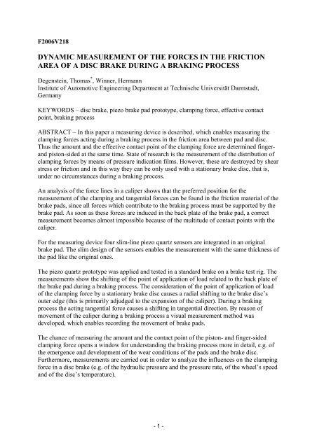
F2006V218<br />
<strong>DYNAMIC</strong> <strong>MEASUREMENT</strong> <strong>OF</strong> <strong>THE</strong> <strong>FORCES</strong> <strong>IN</strong> <strong>THE</strong> <strong>FRICTION</strong><br />
AREA <strong>OF</strong> A DISC BRAKE DUR<strong>IN</strong>G A BRAK<strong>IN</strong>G PROCESS<br />
Degenstein, Thomas * , Winner, Hermann<br />
Institute of Automotive Engineering Department at Technische Universität Darmstadt,<br />
Germany<br />
KEYWORDS – disc brake, piezo brake pad prototype, clamping force, effective contact<br />
point, braking process<br />
ABSTRACT – In this paper a measuring device is described, which enables measuring the<br />
clamping forces acting during a braking process in the friction area between pad and disc.<br />
Thus the amount and the effective contact point of the clamping force are determined finger-<br />
and piston-sided at the same time. State of research is the measurement of the distribution of<br />
clamping forces by means of pressure indication films. However, these are destroyed by shear<br />
stress or friction and in this way they can be only used with a stationary brake disc, that is,<br />
under no circumstances during a braking process.<br />
An analysis of the force lines in a caliper shows that the preferred position for the<br />
measurement of the clamping and tangential forces can be found in the friction material of the<br />
brake pads, since all forces which contribute to the braking process must be supported by the<br />
brake pad. As soon as these forces are induced in the back plate of the brake pad, a correct<br />
measurement becomes almost impossible because of the multitude of contact points with the<br />
caliper.<br />
For the measuring device four slim-line piezo quartz sensors are integrated in an original<br />
brake pad. The slim design of the sensors enables the measurement with the same thickness of<br />
the pad like the original ones.<br />
The piezo quartz prototype was applied and tested in a standard brake on a brake test rig. The<br />
measurements show the shifting of the point of application of load related to the back plate of<br />
the brake pad during a braking process. The consideration of the point of application of load<br />
of the clamping force by a stationary brake disc causes a radial shifting to the brake disc’s<br />
outer edge (this is primarily adjudged to the expansion of the caliper). During a braking<br />
process the acting tangential force causes a shifting in tangential direction. By reason of<br />
movement of the caliper during a braking process a visual measurement method was<br />
developed, which enables recording the movement of brake pads.<br />
The chance of measuring the amount and the contact point of the piston- and finger-sided<br />
clamping force opens a window for understanding the braking process more in detail, e.g. of<br />
the emergence and development of the wear conditions of the pads and the brake disc.<br />
Furthermore, measurements are carried out in order to analyze the influences on the clamping<br />
force in a disc brake (e.g. of the hydraulic pressure and the pressure rate, of the wheel’s speed<br />
and of the disc’s temperature).<br />
- 1 -
TECHNICAL PAPER – <strong>IN</strong>TRODUCTION, MOTIVATION AND STATE <strong>OF</strong> <strong>THE</strong> ART<br />
In this paper a measuring device is introduced which for the first time enables measuring the<br />
clamping forces acting during a braking process in the friction area between pad and disc.<br />
Here the amount and the contact point are determined finger- and piston-sided at the same<br />
time.<br />
The motivation for measuring these quantities is that a lot of processes in the brake are<br />
unknown. This is reflected in the large number of research and development papers as e.g.<br />
papers about braking torque and variations of the friction coefficient, emergence caused by<br />
expansion of DTV (e.g. 14), squeal (e.g. 8), brake judder (e.g. 22), emergence of Hot Spots<br />
(16) and comfort and performance features as well. In many approaches one cautiously<br />
approaches processes during a braking process by simulations of the wheel brake, e.g. (13),<br />
who researches the emergence of Disc Thickness Variation (DTV) by means of a multi-body<br />
model. The input of the simulation model is generally the brake’s clamping force as a causal<br />
effective quantity. Thus, the information about the clamping force can serve to validate the<br />
simulation model. However, as both the amount and the point of application of load of the<br />
clamping force are not available, the piston force (the differences between piston and<br />
clamping force will be discussed later in this paper) is generally used instead.<br />
For future electromechanical vehicle brakes, according to (15), the measurement of the<br />
clamping force in a force measuring pad, for example, would also be a missing “puzzle piece”<br />
in the control circuit of electromechanical braking systems till now. It would not be necessary<br />
any more to estimate the braking torque by complex models for reconstruction of the braking<br />
force.<br />
The main components of a disc brake are the brake pads, the brake disc and the caliper (Fig.<br />
1).<br />
Fig. 1: Components of a disc brake: brake pad, brake disc, caliper<br />
The basic quantities of the forces in a brake are presented in Fig. 2.<br />
y<br />
z<br />
p<br />
AP<br />
brake pad (19)<br />
FC<br />
x<br />
brake pads<br />
µ<br />
brake disc<br />
caliper<br />
FC<br />
brake disc<br />
brake disc<br />
Fig. 2: Forces acting on a disc brake (3, 20, 21)<br />
- 2 -<br />
FT<br />
caliper (5)<br />
ra<br />
brake<br />
pad<br />
direction of rotation<br />
x<br />
z<br />
y
From the hydraulic pressure p and the piston surface AP results the clamping force FC. The<br />
latter causes the tangential force FT = F C ⋅ 2µ<br />
on both friction areas. The tangential force<br />
causes, together with the active friction radius ra, the braking torque M B = FT ⋅ ra.<br />
After all,<br />
the braking torque is the quantity which causes with the help of the dynamic tire radius in the<br />
contact patch of the tire the desired braking force and thus the deceleration of the vehicle.<br />
Detailed researches show that some simplifications are assumed in this model of forces. (4)<br />
Fig. 3 observes the forces acting on a brake pad more exactly.<br />
FP<br />
FC,red<br />
FT<br />
FC,m<br />
∆FC<br />
Fig. 3: Forces acting on a brake pad during a<br />
braking process (4)<br />
A further phenomenon is presented in Fig.<br />
4. The caliper can be assumed model-likely<br />
as a u-profile which inevitably expands<br />
itself under the high clamping forces.<br />
Because of that, shifting of the points of<br />
application of load and therefore a bigger<br />
active friction radius can be expected.<br />
Furthermore, the assumption that no<br />
identical shiftings will appear finger- and<br />
piston-sided seems reasonable, since the<br />
finger side has more elastic qualities than<br />
the piston side with regard to construction.<br />
y<br />
x<br />
z<br />
- 3 -<br />
1 Brake disc<br />
2 Brake pad<br />
3 Back plate<br />
4 Piston<br />
5 Stator (the fixed part of the wheel<br />
brake, connected to the wheel<br />
suspension)<br />
By the support of the tangential force<br />
on the stator a force FC,red opposite to<br />
the brake piston results. Thus, it<br />
shows that the clamping force does<br />
not correspond to the piston force<br />
during a braking process.<br />
Furthermore, this also shows that one<br />
cannot start with a uniform surface<br />
pressing (compare ∆FC) and that the<br />
point of application of load shifts<br />
while braking, correspondingly FC,m,<br />
and does not lie on the same function<br />
line as the piston force.<br />
stator<br />
brake pads<br />
active<br />
radius<br />
brake disc<br />
caliper<br />
expansion<br />
Fig. 4: Caliper expansion under brake pressure
In the analyses of the brake disc is also apparent that the distribution of the surface pressing<br />
brake disc shielding will change by a blow or DTV.<br />
Thermal effects as e.g. the shielding<br />
of a brake disc (Fig. 5) let expect<br />
changes of the surface pressing of the<br />
clamping force as well.<br />
initial<br />
state<br />
after 3<br />
seconds<br />
after 7<br />
seconds<br />
Figures 2 to 5 show that inconsistent/not uniform surface pressing can be expected in a disc<br />
brake. According to (4) this would lead to a slanted wear of the brake pads. Furthermore, a<br />
higher energy expenditure results on the positions with higher surface pressing which leads to<br />
higher temperatures. On the other hand, according to (3), higher temperatures drop to lower<br />
friction coefficients and this reduces the efficiency of the brake. According to (4), the comfort<br />
of the brake is also reduced, since sloping worn pads increase the squealing sensibility.<br />
In order to avoid or reduce the problems mentioned, different measures are used in serial<br />
brakes. Nowadays piston offsets, cuttings in the metal sheet, shiftings of the centre of pressing<br />
of the piston, drawn pads (push-pull principle), two-piston calipers with different piston<br />
diameters and even further measures are used among other things to counteract these effects.<br />
In order to determine the influence of these measures and the actual surface pressing various<br />
methods were developed. State of the art are the tension-optical ball pressing process,<br />
pressure indication films of the company Fuji and electrical pressure indication films of the<br />
company Tekscan (18), for example.<br />
In the tension-optical ball pressing process of the company Girling (4) one 1.5 to 2 mm thick<br />
plastic plate with known tension-optical properties and a ball cage with balls with a diameter<br />
of 3 mm between brake pad and brake disc are laid. By increase of the hydraulic pressure of<br />
the brake system the balls are pressed into the plastic material. Tension curves, which help<br />
one to make statements about the transmitting force, can be seen under polarized light.<br />
Photographs taken by the authors with electrical<br />
pressure indication films show an non-uniform<br />
surface pressing of a brake pad by a hydraulic<br />
pressure of 50bar and a stationary brake disc. The<br />
contact pressure distribution of the clamping force<br />
and the point of application of load calculated by the<br />
red-white rhomb are to be derived.<br />
Further researches with electrical pressure indication<br />
films can be found in (1 and 9), for example.<br />
- 4 -<br />
Fig. 5: Shielding of a brake disc (3)<br />
Fig. 6: A photograph of the fotostress-plastic<br />
plate for the ball pressing process of the<br />
company Girling under polarized light after<br />
load. The number of the interference rings on<br />
the particular ball indentation is a measure for<br />
the pressing dominating there. (4)<br />
⎡ g ⎤<br />
⎢ 2<br />
⎣ cm ⎥<br />
⎦<br />
Fig. 7: Surface pressing distribution<br />
under a brake pad (stationary brake disc)
All these methods have, beside their limited accuracy (e.g. Tekscan fault indication >10%<br />
(18)) the disadvantage that they can be only applied by a stationary brake disc. According to<br />
Fig. 3, however, it appears that during the braking process other distributions lead to the<br />
clamping force by the support of the tangential force. By these methods the effect of the<br />
caliper expansion can be primarily examined, which, however, will not behave in the same<br />
way during the braking process as one by a stationary disc. Measuring methods for<br />
determination of the clamping force during a braking process do not exist until now.<br />
The focus of this work lays on the determination of the point of application of the clamping<br />
force of the finger and piston side during the braking process correspondingly to Fig. 8.<br />
FC,piston<br />
Fig. 8: Shifting of the point of application of the clamping force<br />
DESIGN <strong>OF</strong> <strong>THE</strong> MEASUR<strong>IN</strong>G SYSTEM<br />
In order to measure the desired forces, an analysis of the force lines in a disc brake is<br />
necessary. For this analysis and the following measurements a two-piston finger framework<br />
caliper of the company Continental Teves (type 2 FNR-Al42, fig. 1) was chosen. This caliper<br />
is currently used in many upper class vehicles.<br />
In Fig.9 the force lines of the clamping and the tangential force are qualitatively presented.<br />
force lines<br />
p<br />
FT,piston<br />
brake disc<br />
FT,finger<br />
FC,finger<br />
f<br />
Fig. 9: Force Lines in a caliper<br />
- 5 -<br />
FC,piston<br />
rC,p<br />
rC,f<br />
FC,finger<br />
caliper
It can be derived that the clamping forces branch<br />
as soon as they are induced into the back plate.<br />
One part of the clamping force flows over the<br />
finger respectively the pistons and another part<br />
over the stator. To be able to register the whole<br />
clamping force, it must be first measured in the<br />
friction material (Fig. 10) before it is introduced<br />
into the back plate. If the force would be<br />
registered on the piston, for example, the portion<br />
that flows over the stator could not be registered.<br />
This corresponds to the model concept of Fig. 3<br />
that the piston force is not equivalent to the<br />
clamping force.<br />
Important selection criteria for the sensor technology are the forces to be transmitted (up to<br />
40kN), the building space requirement (integrable in a brake pad), use in a serial caliper,<br />
quasi-statical and dynamical measurement, low temperature dependency…<br />
After comparing a number of sensor principles (among others strain gauges, piezo ceramics,<br />
capacitive sensors…) the use of the piezo-electrical (Fig. 11) effect was chosen. (12, page<br />
184)<br />
F<br />
Fig. 11: Piezo-electrical effect without/under force effect / piezo quarz material (2)<br />
Detail information about piezo quartz sensors can be found in (17). In the end piezo quartz<br />
sensors of the company Kistler of type 9136B (Fig. 12) were chosen.<br />
Fig. 12 Piezo quartz sensors principle and sensor (10)<br />
F<br />
Decisive were, besides the big measurement range, the low building height and the stiffness<br />
that approximately corresponds to the pad's back plate of steel. The temperature range is<br />
sufficient. In comparison, the adhesive with which the brake pad is fastened to the back plate<br />
- 6 -<br />
caliper<br />
stator<br />
sensor positions<br />
brake disc<br />
Fig. 10: Measuring position of the sensors<br />
for registration of the clamping force<br />
Excerpt from the data sheet (10)<br />
• Measuring range 0 – 60 kN<br />
• Stiffness 8 kN/µm<br />
• Inside diameter 12,1 mm<br />
• Outside diameter 30 mm<br />
• Height 4 mm<br />
• Temperature range: -20 to 120°C<br />
• Weight 14 g
is resistant up to approx. 300°. These temperatures are reached only after various processes of<br />
braking at high speeds. For the planned researches high temperatures are reached at the brake<br />
disc only for a short time. The air cooling available at braking test benches is sufficient to<br />
keep the sensors in the permissible temperature field of application.<br />
STRUCTURE <strong>OF</strong> <strong>THE</strong> MEASUR<strong>IN</strong>G BRAKE PAD:<br />
For the measuring of the point of application of load<br />
of the clamping force four piezo quartz sensors are<br />
built between the back plate and a support plate (Fig.<br />
13).<br />
Fig. 13: CAD Model of the piezo prototype<br />
Fig. 14: position of the piezo quarz sensors<br />
Fig. 15 shows the original brake pad compared to the Piezo prototype of the 2. generation.<br />
Fig. 15: Original brake pad and Piezo<br />
prototype<br />
CALIBRATION <strong>OF</strong> <strong>THE</strong> BRAKE PADS<br />
The calibration of the Piezo prototype is carried<br />
out on a calibrating station (Fig. 16) designed<br />
especially for this application case. With its help<br />
forces can be applied at the same time in two<br />
directions.<br />
With this construction forces can be applied to the<br />
brake pad one by one or simultaneously, statically<br />
or dynamically. For a defined force flow this<br />
occurs with the help of balls (recognizable at the<br />
arrowheads of the forces in Fig. 16).<br />
- 7 -<br />
4 sensors<br />
back plate<br />
friction<br />
material<br />
Fig. 14 shows the real sensors on the adapter<br />
plate (the back plate was removed for this<br />
photograph). To determine the acting clamping<br />
force the aggregated signal of the four single<br />
forces is formed. The point of application of<br />
load is determined by a moment balance in the<br />
sensor measuring level.<br />
The main difference between the original and the<br />
iPad is the steel plate and the reduction of the<br />
friction material's thickness connected to it. The<br />
expected low compression ability of the brake pad<br />
could be counteracted by a suitable choice of the<br />
friction material. This could be proved in a<br />
compression tester for brake pads. The pad shown<br />
had a deformation of 300 µm at a maximum<br />
testing pressure of 160 bar (with the original piston<br />
surface) - this value lies in the standard range of an<br />
European brake pad (11 and 19).<br />
FX<br />
FY<br />
Piezo<br />
Prototype<br />
Fig. 16: Calibration station of the<br />
Piezo prototype
TEST SETUP AND TEST PARAMETERS<br />
For the test execution the prepared brake pads<br />
were fitted into the caliper above<br />
correspondingly to Fig. 17. The following<br />
researches were carried out at the centrifugal<br />
force test bench of the industrial partner, the<br />
TMD Friction Ltd. (19) Fig. 18 left, as well as<br />
at the chair’s own roll test bench (Fig. 18<br />
right). The same brake was used; the<br />
advantage of the use of a centrifugal force test<br />
bench is the better accessibility of the<br />
components. The advantage of using a roll test<br />
bench is the nearer illustration of the reality,<br />
since parts of the original suspension are also<br />
used along with the wheel and the caliper’s<br />
motion is thus shown as well.<br />
power<br />
unit<br />
8 sensors<br />
supplies (piezos)<br />
brake disc<br />
thermo<br />
elements<br />
torque<br />
measurement<br />
- 8 -<br />
Fig. 17: Brake pads with integrated piezo<br />
quartz sensors assembled in the caliper<br />
(without a stator)<br />
original wheel<br />
suspension<br />
Fig. 18 left: Test execution on TMD brake test rig; right: test execution on FZD roll test rig<br />
The wirings of the eight piezo quartz sensors are led through the gap between stator and frame<br />
of the caliper to a charge amplifier. Further the temperature of the brake disc, the temperature<br />
of the sensors, the brake pressure, the speed and the braking torque are recorded. The<br />
reproduction of the vehicle parameters is carried out for the vehicle mass with the<br />
corresponding centrifugal force of the test bench. The air amount for the cooling of the<br />
components corresponds to the flow of a brake of an upper class vehicle.<br />
The following test parameters were chosen:<br />
• Brake pressure: Series in 10 bar – steps from 0 to 60 bar (> 60 bar blocks the wheel)<br />
• Wheel speed 0 m/s (stationary wheel) and braking from 15 and 30 to 0 m/s<br />
• Brake disc’s temperature at the beginning of a braking < 100°C (to protect the sensors)<br />
MOVEMENT <strong>OF</strong> <strong>THE</strong> BRAKE PAD REGARD<strong>IN</strong>G <strong>THE</strong> CENTRE <strong>OF</strong> <strong>THE</strong> BRAKE DISC<br />
The determination of the point of application of load of the clamping force is carried out with<br />
sensors which are in the brake pads. The centre of the wheel or the brake disc is regarded as a<br />
reference point of the radius. The design of a vehicle brake allows on the one hand<br />
movements of the caliper, on the other movements of the brake pads during a braking process.
For this reason it was necessary to develop a measurement method which enables recording<br />
the movement of a brake pad during a braking. Finally a visual measurement method was<br />
used with a resolution of 10.2 million pixel. With regard to the following photographs, a pixel<br />
corresponds to 0.124 mm - this therefore also corresponds to the maximum precision of this<br />
method. Fig. 19 shows exemplarily the movement of the finger-sided brake pad during a<br />
braking with a braking pressure of 40 bar.<br />
RESULTS<br />
Fig. 19: Movement of a brake pad<br />
during a braking with 40 bar<br />
As expected, the brake pad is drawn in the direction of rotation. Furthermore, it easily<br />
screws out intake-sided correspondingly to the acting forces. Therefore, the sensors move<br />
outtake-sided insignificantly in the direction of the wheel's centre. For the determination of<br />
the point of application of load, which is near the middle of the pad's back plate, it means in<br />
this case a deviation of approx. 0.66 mm, which has to be added to the measured value. By<br />
using other caliper types this value can turn out considerably greater, since frame brakes are<br />
construction-relatedly considerably stiffer than e.g. simple finger brakes.<br />
The indications of the positions of the sensors in the<br />
brake pad for the following results correspond to<br />
Fig. 20.<br />
The course of the four sensors of the piston-sided<br />
pad is exemplarily presented in Fig. 21 at a braking<br />
pressure of 40 bar and a stationary brake disc. In<br />
Fig. 22 is the course during a braking process with<br />
an initial speed of 15 m/s (425 rpm).<br />
- 9 -<br />
1 2<br />
3 4<br />
Fig. 20: Indication of the sensors<br />
in the brake pad
FY [kN], p [10 bar]<br />
5<br />
4<br />
3<br />
2<br />
1<br />
0<br />
-1<br />
It can be derived that the outer sensors transfer the greater forces. This rises further at an<br />
increasing braking pressure – this corresponds to the model concept of expanding the caliper<br />
at increasing pressure.<br />
In Fig. 23 the results of the measurements for the stationary brake disc and for the braking<br />
with an initial speed of 30 m/s (850 rpm) at finger- and at piston-sided pad are summarized.<br />
The representation corresponds to Fig. 21 from the view on the back plate.<br />
radial [mm]<br />
500<br />
rpm<br />
p p<br />
1<br />
2<br />
rpm<br />
0 0.5 1 1.5 2 2.5 3 -100<br />
3<br />
0 rpm 850 --> 0 rpm<br />
10<br />
8<br />
finger side 0 rpm<br />
6<br />
4<br />
2<br />
0<br />
piston side 0 rpm<br />
finger side 850 --> 0 rpm<br />
piston side 850 --> 0 rpm<br />
60 bar 60 bar<br />
-2<br />
-4<br />
-6<br />
∆ = 10 bar<br />
-8<br />
-10<br />
10 bar<br />
10 bar<br />
-12<br />
-14<br />
tolerance less than 1 mm<br />
10 bar<br />
hydraulic pressure<br />
-10 -8 -6 -4 -2 0 2 4 6 8 10<br />
trailing edge tangential [mm] leading edge<br />
Fig. 23: Shifting of the point of application of load during a braking process<br />
4<br />
rel. tolerance less than 1,5%<br />
Fig. 21: Course of the normal forces of<br />
the single sensors of the piston-sided pad<br />
(stationary brake disc)<br />
400<br />
300<br />
200<br />
100<br />
0<br />
It can be derived that the point of application of load moves by 7mm piston-sided to the<br />
outside by a stationary brake disc when the braking pressure rises from 10 to 60 bar. This<br />
effect is finger-sided by approx. 17mm clearly greater. This can be explained by the design of<br />
a brake (compare Fig. 4), since the brake is connected to the suspension piston-sided and so it<br />
is stiffer than the finger side, which has to be lead over the brake disc. During a braking<br />
process the points of application of load shift into the direction of the leading edge. This<br />
corresponds to the model concept according to (4), compare Fig. 3. If these results are<br />
transferred to the change of the friction radius, a rise of the braking torque by approx. 7% for<br />
- 10 -<br />
FY [kN], p [10 bar]<br />
5<br />
4<br />
3<br />
2<br />
1<br />
0<br />
-1<br />
3<br />
1<br />
rpm<br />
0 0.5 1 1.5 2 2.5 3 3.5<br />
2<br />
4<br />
rel. tolerance less than 2%<br />
Fig. 22: Course of the normal forces of<br />
the single sensors of the piston-sided pad<br />
(during braking process)<br />
500<br />
400<br />
300<br />
200<br />
100<br />
0<br />
rpm<br />
-100
this brake by braking pressure of 60 bar. If one compares this result with the error analysis of<br />
the determination of the friction value of (6), who has determined a range of 10% for the<br />
tolerance band of the friction value under the assumption of a constant friction radius, these<br />
measurements confirm the assumption of (6) that the biggest error influence can be caused by<br />
the neglect of the change of the friction radius.<br />
CONCLUSION AND OUTLOOK<br />
The measurement device presented here enables for the first time the measuring of the<br />
amounts and points of application of the clamping forces during a braking process. The model<br />
concepts according to (4) and the enlarging of the caliper under brake pressure (Fig. 4) could<br />
be confirmed for this caliper.<br />
The sensor integration in the brake pad makes it possible to apply this design principle in<br />
almost every disc brake. Since smaller brakes have to transfer lower forces, smaller sensors<br />
could be used. By a measuring range from 0 to 15 kN the sensors’ diameter decreases from 30<br />
to 16 mm (10).<br />
Among others, the benefit lays in the one-time determination of the change of the point of<br />
application of load for a defined caliper. Subsequently, this information can be used as a<br />
correction factor for test bench experiments and so some factors of the real friction coefficient<br />
can be determined more exactly. The measurement device can now also be examined for a<br />
uniform pressing of the brake pad on the brake disc during a braking process. Piezo quartz<br />
sensors are very suitable for high frequency measurements. Thus, changes in the clamping<br />
force can also be recorded in the range of squeal frequencies (up to approx. 20 kHz).<br />
Further benefit can be found for investigation of brake disc geometrical failures (e.g. run-out,<br />
disc thickness variation), which are reflected in changes of the point of application of load<br />
dependent on the speed. In such researches a kind of a circular movement of the point of<br />
application of load with a movement diameter of 1-2 mm was determined. This information<br />
could be very helpful for investigations of e.g. judder and variation of brake torque.<br />
According to the device shown shear sensors with identical measurements of the sensors used<br />
for direct measurement of the tangential forces as well. These researches are currently<br />
continued at the Automotive Engineering Department of Darmstadt FZD with the aim to<br />
determine the active friction radius with the help of the known braking torque from the test<br />
bench.<br />
The stacking of these sensors is also possible and thus the simultaneous measurement of the<br />
clamping and tangential component and therefore the direct determination of the brake pad on<br />
all four sensor positions. However, it is thereby problematic that the original thickness of the<br />
brake pads is exceeded and thus the brake in hand can be falsified in its features as e.g. the<br />
support of the forces.<br />
Nevertheless, in order to enable a measurement, the use of piezo ceramics is currently tested.<br />
These are considerably thinner (from 0.5 mm) and can also be used as shear and normal force<br />
sensors. Together with the less required space, the explicitly favorable lower costs should be<br />
mentioned. Disadvantageous are the relatively heavy losses of charge during a static load<br />
which possibly prevents a measurement of these quantities with piezo ceramics.<br />
ACKNOWLEDGEMENTS<br />
The authors would like to thank the TMD Friction Group for the outstanding cooperation and<br />
financing this research project.<br />
- 11 -
REFERENCES<br />
(1) Abu Baker, A.R., Ouyang, H. and Siegel, J.E. “Brake pad surface topography Part I:<br />
Contact Pressure Distribution“ SAE Technical Paper 2005-01-3941<br />
(2) Bill, Bernhard ”Messen mit Kristallen – Grundlagen und Anwendungen der<br />
piezoelektrischen Messtechnik“ Die Bibliothek der Technik, Band 227, Verlag<br />
moderne Industrie, 2002<br />
(3) Breuer, Bert; Bill, Karlheinz ”Bremsenhandbuch – Grundlagen, Komponenten,<br />
Systeme, Fahrdynamik; 2. Auflage, ATZ-MTZ-Fachbuch, Vieweg Verlag, 2004<br />
(4) Burckhardt, Manfred ”Fahrwerktechnik: Bremsdynamik und Pkw-Bremsanlagen“,<br />
Prof. Dipl.-Ing. Jörnsen Reimpell (Editor), Vogel Fachbuch Kraftfahrzeugtechnik,<br />
Vogel Buchverlag, Würzburg, 1991<br />
(5) www.continentalteves.com, 2006<br />
(6) Degenstein, T.; Dohle, A.; Elvenkemper, J.; Lange, J. * , ”The µ-value – Friction<br />
Determination in Brake Systems“ 16./17. Juni 2006, Bad Neuenahr, VDI-Fortschritt-<br />
Berichte Reihe 12 Nr. 620, Düsseldorf: VDI-Verlag; 2006<br />
(7) Engel, Hans Georg ”Systemansatz zur Untersuchung von Wahrnehmung, Übertragung<br />
und Anregung bremserregter Lenkunruhe in Pkw“ Dissertation, FZD, TUD, VDI-<br />
Fortschritt-Berichte Reihe 12 Nr. 354, Düsseldorf: VDI-Verlag; 1989<br />
(8) Eriksson, Mikael ”Friction and Contact Phenomena of Disc Brakes Related to<br />
Squeal“, ACTA Universitatis Upsaliensis, Uppsala 2000<br />
(9) Hammerström, L. et.al. ”Pressure Sensitive Film as a tool for investigation the<br />
pressure distribution on brake pads“ Tribology; Nordtrip 2002<br />
(10) Kistler Instrumente AG Slimline Sensoren (SLS) ”Messen von dynamischen und<br />
quasistatischen Kräften Typ 9130B – Typ 9136B.“. Data sheet 000-110d-02.02<br />
(DB06.020d-02.02), Kistler Instrumente AG, Winterthur, 2002<br />
(11) Oehl, K.-H.; Paul, H.-G. ”Bremsbeläge für Straßenfahrzeuge – Entwicklung und<br />
Erprobung“ Die Bibliothek der Technik, Band 49, Verlag moderne Industrie, 1990<br />
(12) Schrüfer, Elmar ”Elektrische Messtechnik“ 8. edition, Technische Universität<br />
München, Carl Hanser Verlag München Wien, München, 2004<br />
(13) Schumann, Marcus ”Analysis method for assessing irregular brake disc wear on motor<br />
vehicle disc brakes“ 16./17. Juni 2006, Bad Neuenahr, VDI-Fortschritt-Berichte Reihe<br />
12 Nr. 620, Düsseldorf: VDI-Verlag; 2006<br />
(14) Schumann, Marcus ”Vehicle brake disc wear progression model“ brems.tech,<br />
München, 2004<br />
(15) Schwarz, Ralf ”Rekonstruktion der Bremskraft bei Fahrzeugen mit elektromechanisch<br />
betätigten Radbremsen“ Dissertation, Institut für Automatisierungstechnik (IAT),<br />
TUD, Fortschritt-Berichte VDI, Reihe 12 Nr. 393, VDI-Verlag, 1999<br />
(16) Suryatama, D. et. al. ”Contact Mechanics Simulation for Hot Spots Investigation“<br />
Society of Automotive Engineers, Inc., 2001<br />
(17) Tichy, J.; Gautschi G. ”Piezoelektrische Messtechnik – Physikalische Grundlagen,<br />
Kraft-, Druck- und Beschleunigungsaufnehmer, Verstärker“ Springer Verlag, Berlin<br />
Heidelberg New York, 1980<br />
(18) Tekscan ”Industrial Sensor Catalog“ RevDD_072705, Tekscan, 2005<br />
(19) www.tmdfriction.de, 2006<br />
(20) Wallentowitz, H.: “Vertikal- / Querdynamik von Kraftfahrzeugen”,<br />
Forschungsgesellschaft Kraftfahrwesen, Aachen mbH (fka), 1997<br />
(21) Winner, Hermann ”Kraftfahrzeuge I – Folien zur Vorlesung“ Technische Universität<br />
Darmstadt, Automotive Engineering Department (FZD), Darmstadt, 2004<br />
(22) Vries, Alexander de ”The Brake Judder Phenomenon“ SAE 920554, 1992<br />
- 12 -