Test Procedure for Hum Modulation - SCTE
Test Procedure for Hum Modulation - SCTE
Test Procedure for Hum Modulation - SCTE

You also want an ePaper? Increase the reach of your titles
YUMPU automatically turns print PDFs into web optimized ePapers that Google loves.
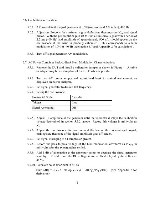
5.6. Calibration verification:<br />
5.6.1. AM modulate the signal generator at 0.5%(conventional AM index), 400 Hz.<br />
5.6.2. Adjust oscilloscope <strong>for</strong> maximum signal deflection, then measure V p-p and signal<br />
period. With the pre-amplifier gain set to 100, a sinusoidal signal with a period of<br />
2.5 ms (400 Hz) and amplitude of approximately 900 mV should appear on the<br />
oscilloscope if the setup is properly calibrated. This corresponds to a hum<br />
modulation of 1.0% or -40 dB (see section 5.7 and Appendix 2 <strong>for</strong> calculations).<br />
5.6.3. Turn off signal generator AM modulation.<br />
5.7. AC Power Combiner Back-to-Back <strong>Hum</strong> <strong>Modulation</strong> Characterization:<br />
5.7.1. Remove the DUT and install a calibration jumper as shown in Figure 1. A cable<br />
or adapter may be used in place of the DUT, when applicable.<br />
5.7.2. Turn on AC power supply and adjust load bank to desired test current, as<br />
displayed on power analyzer.<br />
5.7.3. Set signal generator to desired test frequency.<br />
5.7.4. Set-up the oscilloscope:<br />
Horizontal Scale<br />
Trigger<br />
Signal Averaging<br />
5 ms/div<br />
Line<br />
Off<br />
5.7.5. Adjust RF amplitude at the generator until the voltmeter displays the calibration<br />
voltage determined in section 5.5.2, above. Record this voltage in millivolts as<br />
V a .<br />
5.7.6. Adjust the oscilloscope <strong>for</strong> maximum deflection of the non-averaged signal,<br />
making sure that none of the signal amplitude goes off-screen.<br />
5.7.7. Set signal averaging to 64 samples or greater.<br />
5.7.8. Record the peak-to-peak voltage of the hum modulation wave<strong>for</strong>m as mV p-p in<br />
millivolts after the averaging has settled.<br />
5.7.9. Add 1 dB of attenuation at the generator output or decrease the signal generator<br />
level by 1 dB and record the DC voltage in millivolts displayed by the voltmeter<br />
as V b .<br />
5.7.10. Calculate noise floor hum in dB as:<br />
<strong>Hum</strong> (dB) = -19.27 –20Log(V a -V b ) + 20Log(mV p-p /100)<br />
derivation)<br />
(See Appendix 2 <strong>for</strong><br />
5