Sintered Metal Element - SMC
Sintered Metal Element - SMC
Sintered Metal Element - SMC

You also want an ePaper? Increase the reach of your titles
YUMPU automatically turns print PDFs into web optimized ePapers that Google loves.
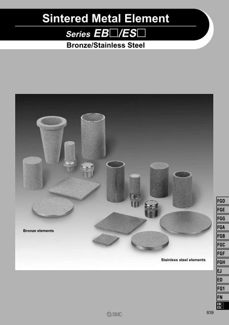
<strong>Sintered</strong> <strong>Metal</strong> <strong>Element</strong><br />
Series EB/ES<br />
Bronze/Stainless Steel<br />
Bronze elements<br />
Stainless steel elements<br />
839<br />
FGD<br />
FGE<br />
FGG<br />
FGA<br />
FGB<br />
FGC<br />
FGF<br />
FGH<br />
EJ<br />
ED<br />
FQ1<br />
FN<br />
EB<br />
ES
840
Product Configurations of <strong>Sintered</strong> <strong>Metal</strong> <strong>Element</strong>s<br />
Configuration Bronze elements (BC) Stainless steel elements (SUS)<br />
Disc<br />
øD<br />
t<br />
Series EBD<br />
(P.844)<br />
· With outside diameter<br />
cutting finish<br />
· Without outside diameter<br />
cutting finish<br />
øD<br />
t<br />
Series ESD<br />
(P.847)<br />
· With outside diameter<br />
cutting finish<br />
· Without outside diameter<br />
cutting finish<br />
Square<br />
sheet<br />
L<br />
W<br />
t<br />
Series EBS<br />
(P.844)<br />
· With external shearing<br />
finish<br />
· With external machining<br />
finish<br />
L<br />
W<br />
t<br />
Series ESS<br />
(P.848)<br />
· With external shearing<br />
finish<br />
· With external machining<br />
finish<br />
L<br />
Cylinder<br />
øD<br />
t<br />
L<br />
Series EBP<br />
(P.845)<br />
—<br />
øD<br />
Welding<br />
t<br />
Welding<br />
Series ESP<br />
(P.849)<br />
· Seamless finish<br />
(molded product)<br />
· With seams<br />
(welded product)<br />
Welding<br />
L<br />
Cylinder<br />
with<br />
bottom<br />
øD<br />
L<br />
t<br />
Series EBW<br />
(P.845)<br />
—<br />
øD<br />
Welding<br />
t<br />
Welding<br />
Series ESW<br />
(P.850)<br />
· Seamless finish<br />
(molded product)<br />
· With seams<br />
(welded product)<br />
Welding<br />
Welding<br />
L<br />
Cone with<br />
flange<br />
øD1<br />
t1<br />
øD2<br />
Series EBF<br />
(P.846)<br />
—<br />
—<br />
—<br />
—<br />
t2<br />
A<br />
FGD<br />
B<br />
FGE<br />
A<br />
A<br />
FGG<br />
B<br />
B<br />
FGA<br />
<strong>Element</strong><br />
with fitting<br />
Hex width<br />
across flats C<br />
A<br />
P.846<br />
· With fitting<br />
(M3, M5, R1/8,<br />
R1/4, R3/8, R1/2)<br />
Hex width<br />
across flats C<br />
A<br />
B<br />
P.851<br />
· With fitting<br />
(M3, M5, R1/8,<br />
R1/4, R3/8, R1/2)<br />
FGB<br />
FGC<br />
FGF<br />
B<br />
Hex width<br />
across flats C<br />
Hex width<br />
across flats C<br />
A<br />
FGH<br />
EJ<br />
B<br />
ED<br />
Features<br />
<strong>Sintered</strong> material: CAC403 equivalent<br />
(<strong>Metal</strong> material of elements with fitting: brass)<br />
• Produces 2CuCO3·Cu(OH)2 (patina) in the atmosphere,<br />
providing good corrosion resistance.<br />
<strong>Sintered</strong> material: SUS316L equivalent<br />
(<strong>Metal</strong> material of elements with fitting: stainless steel)<br />
· Austenite stainless steel with good corrosion resistance to<br />
acids, alkaline substances, and other chemicals<br />
841<br />
FQ1<br />
FN<br />
EB<br />
ES
<strong>SMC</strong> sintered metal elements are suitable<br />
for a wide range of industrial applications.<br />
High mechanical strength and withstand pressure<br />
Anti-corrosion<br />
Suitable for high-accuracy filtration<br />
Suitable for machining, crimping, brazing, welding, and simultaneous sintering<br />
Washing allows repeated use<br />
Applications<br />
Specifications<br />
Item<br />
Material<br />
Sintering density (g/cm 3 )<br />
Void ratio (%)<br />
Operating temperature range (°C)<br />
Thermal expansion coefficient (/°C)<br />
Bronze<br />
CAC403 equivalent<br />
5.0 to 6.5<br />
25 to 43<br />
–160 to 200<br />
1.8 x 10 –5 Stainless steel<br />
SUS316L equivalent<br />
4.2 to 5.2<br />
36 to 48<br />
–250 to 550<br />
1.6 x 10 –5<br />
Tensile strength (MPa)<br />
Nominal filtration accuracy (µm)<br />
Abbreviated/Nominal (µm)<br />
Typical configurations<br />
9.8 to 83.4<br />
(1), 2, 5, 10, 20<br />
40, 70, 100, 120<br />
Disc, square sheet, cylinder, cylinder with bottom, cone with flange, element with fitting, etc.<br />
Note 1) Sintering density, void ratio, and tensile strength differ according to nominal filtration accuracy.<br />
Note 2) Thermal expansion coefficient applies to stainless steel or bronze material, not to sintered metal elements.<br />
Note 3) Nominal filtration accuracy of 1 µm is an optional value.<br />
Raw material categories and nominal filtration accuracy (µm)<br />
Sieve (mesh)<br />
Opening (µm)<br />
Nominal filtration<br />
accuracy (µm)<br />
20<br />
850<br />
24<br />
710<br />
32<br />
500<br />
42<br />
355<br />
60<br />
250<br />
80<br />
180<br />
120<br />
125<br />
200<br />
75<br />
120 100 70 40 20 10 5 2<br />
Note 1) Sieve (mesh) and opening values apply to metal mesh separating raw material, not to elements.<br />
Note 2) Nominal filtration accuracy: Refers to value used to categorize raw material, not to filtration rating.<br />
(Refer to the page 854 for “11 Nominal filtration accuracy”.)<br />
Raw Material Powder and <strong>Sintered</strong> <strong>Metal</strong> <strong>Element</strong><br />
<br />
<br />
842<br />
<br />
<br />
250<br />
63<br />
A sintered metal element consists of countless interconnected<br />
capillary tubes, making it suitable<br />
for a wide range of uses. For detailed information<br />
on purpose-specific applications, please contact<br />
<strong>SMC</strong>.<br />
1. Filtration<br />
<strong>Sintered</strong> metal elements are widely used for removing<br />
foreign particles from many different kinds<br />
of flow media.<br />
Major application fields: General gases, water,<br />
various kinds of oils<br />
Normally, filtration makes use of the so-called<br />
bridge effect where foreign particles are<br />
blocked because they form a bridge-like accumulation.<br />
The size and distribution of particles to be filtered<br />
can be controlled through parameters<br />
such as the diameter of the capillary tubes.<br />
Particles may be blocked completely or selectively.<br />
Foreign<br />
particles<br />
Before<br />
filtration<br />
A<br />
Filtration<br />
Capillary<br />
tubes<br />
Fluid being<br />
filtered<br />
Enlarged view<br />
of section A,<br />
showing bridge<br />
effect<br />
2. High-viscosity filtration<br />
This is used to remove foreign matter or gel from<br />
raw materials for fibers or films.<br />
3. Sound absorption<br />
The porous quality of sintered metal elements allows<br />
them to absorb sound energy, providing a<br />
muffling or silencing effect.<br />
4. Gas removal<br />
<strong>Sintered</strong> metal elements are used for degassing<br />
purposes in forming and molding processes.<br />
5. Foaming<br />
<strong>Sintered</strong> metal elements positioned in various<br />
kinds of fluids are used to introduce gases, for<br />
stirring and other purposes.<br />
6. Flow control<br />
Because a sintered metal element consists of<br />
countless interconnected capillary tubes, it can be<br />
used to control the flow of fluids. Cylindrical<br />
bronze elements are especially suited for this<br />
type of application.<br />
7. Other applications<br />
Various other applications make use of the fluidpassing<br />
functionality of sintered metal elements.<br />
Flow Rate Characteristics<br />
Fluid: Air<br />
10<br />
Pressure drop ∆P (kPa)<br />
Pressure drop ∆P (kPa)<br />
1<br />
0.1<br />
0.01<br />
0.1 1 10<br />
Flow rate per unit area (l/min (ANR)/m 2 )<br />
Fluid: Air<br />
100<br />
Bronze (BC)<br />
Stainless steel (SUS)<br />
10<br />
1<br />
Nominal value 1 µm<br />
<strong>Element</strong> thickness: 3 mm<br />
Temperature: 20°C<br />
Viscosity coefficient: 1.8 x 10 –5 Pa·s<br />
Nominal value 2 µm<br />
Nominal value 5 µm<br />
Nominal value 10 µm<br />
Nominal value 20 µm<br />
Nominal value 40 µm<br />
Nominal value 70 µm<br />
Nominal value 100 µm<br />
Nominal value 120 µm<br />
<strong>Element</strong> thickness: 2.3 mm<br />
Temperature: 20°C<br />
Viscosity coefficient: 1.8 x 10 –5 Pa·s<br />
Nominal value 1 µm<br />
Nominal value 2 µm<br />
Nominal value 5 µm<br />
Nominal value 10 µm<br />
Nominal value 20 µm<br />
Nominal value 40 µm<br />
Nominal value 70 µm<br />
Nominal value 100 µm<br />
Nominal value 120 µm<br />
0.1<br />
0.1 1 10<br />
Flow rate per unit area (l/min (ANR)/m 2 )<br />
Fluid: Water<br />
100 Nominal<br />
value 1 µm<br />
Nominal<br />
value 2 µm<br />
Pressure drop ∆P (kPa)<br />
Pressure drop ∆P (kPa)<br />
10<br />
1<br />
0.1<br />
0.1 1 10<br />
Flow rate per unit area (l/min/m 2 )<br />
Fluid: Water<br />
1000<br />
100<br />
10<br />
Nominal value 10 µm<br />
Nominal value 5 µm<br />
Nominal value 1 µm<br />
Nominal value 20 µm<br />
Nominal value 2 µm<br />
<strong>Element</strong> thickness: 3 mm<br />
Temperature: 20°C<br />
Viscosity coefficient: 1 x 10 –3 Pa·s<br />
Nominal value 40 µm<br />
Nominal value 70 µm<br />
Nominal value 5 µm<br />
Nominal value 10 µm<br />
Nominal value 20 µm<br />
Nominal value 40 µm<br />
Nominal value 70 µm<br />
Nominal value 100 µm<br />
Nominal value 120 µm<br />
Nominal value<br />
100 µm<br />
Nominal value<br />
120 µm<br />
<strong>Element</strong> thickness: 2.3 mm<br />
Temperature: 20°C<br />
Viscosity coefficient: 1 x 10 –3 Pa·s<br />
1<br />
0.1 1 10<br />
Flow rate per unit area (l/min/m 2 )<br />
Note) Flow rate characteristics for stainless steel elements ESP-ESW (diameter 120 mm or less, no ESD seams) are different.<br />
<br />
The state equation of an ideal gas (PV/T = constant) and the pressure drop are proportional to element thickness and viscosity. Based on this, the pressure<br />
drop under conditions that are different from those used in the flow rate characteristics chart can be calculated roughly for reference, using the following<br />
simplified procedure.<br />
(1) Pressure drop ∆P kPa when flow medium is air, temperature T1°C, pressurization P1 kPa:<br />
101.3 x ∆P0 x (273 + T1)<br />
∆P0: Pressure drop kPa obtained from flow rate characteristics chart<br />
∆P=<br />
293 x (P1 + 101.3)<br />
(2) <strong>Element</strong> thickness dependent pressure drop ∆P kPa when flow medium is air and water, element thickness t1 mm, and element thickness in flow rate<br />
characteristics chart differs:<br />
∆P0: Pressure drop kPa obtained from flow rate characteristics chart or from (1)<br />
t1<br />
∆P=∆P0 x<br />
t0: <strong>Element</strong> thickness in flow rate characteristics chart (BC element = 3 mm/ SUS element<br />
t0 (2.3 or 3)<br />
= 2.3 mm)<br />
(3) Pressure drop ∆P kPa when viscosity η 1 of flow medium<br />
differs from that of air or water:<br />
η1<br />
∆P=∆P0 x<br />
η 0<br />
∆P0: Pressure drop kPa obtained from flow rate characteristics chart<br />
η 1 : Viscosity of flow medium Pa·s<br />
η 0 : Viscosity of flow rate characteristics chart (air = 1.8 x 10 –5 Pa·s, water = 1 x 10 –3 Pa·s)<br />
843<br />
FGD<br />
FGE<br />
FGG<br />
FGA<br />
FGB<br />
FGC<br />
FGF<br />
FGH<br />
EJ<br />
ED<br />
FQ1<br />
FN<br />
EB<br />
ES
<strong>Sintered</strong> <strong>Metal</strong> <strong>Element</strong><br />
Standard Configurations and Dimensions (Unit: mm)<br />
Bronze (BC)<br />
1. Disc<br />
How to Order<br />
EBD 6<br />
øD<br />
2 5<br />
Nominal filtration accuracy (µm)<br />
2<br />
5<br />
10<br />
20<br />
40<br />
70<br />
100<br />
120<br />
t<br />
Outside diameter<br />
finish category<br />
Nil<br />
M<br />
Without cutting finish<br />
With cutting finish<br />
øD<br />
t<br />
Standard dimensions product (no cutting finish)<br />
øD<br />
t<br />
µm<br />
Manufacturing range for product<br />
without cutting finish<br />
øD<br />
t<br />
µm<br />
1<br />
2 to 20<br />
2 to 30<br />
1.5<br />
2 to 40<br />
2 to 10<br />
2 to 120<br />
Tolerance<br />
øD ± 0.3<br />
t ± 0.3<br />
Note ) Smallest unit for specifying diameter D values is 1 mm, and 0.5 mm for t<br />
values.<br />
Manufacturing range for product with cutting finish<br />
øD<br />
t<br />
µm<br />
Tolerance<br />
øD<br />
t<br />
6<br />
2<br />
30 to 200<br />
1<br />
2 to 20<br />
± 0.3<br />
± 0.5<br />
± 0.8<br />
± 0.3<br />
± 0.5<br />
8<br />
2<br />
10<br />
2<br />
12<br />
3<br />
2 to 120<br />
30 to 300<br />
1.5<br />
2 to 40<br />
15<br />
3<br />
Note ) For products with non-standard dimensions, sintering mold is required.<br />
Please contact <strong>SMC</strong>.<br />
20<br />
3<br />
30 to 400<br />
2 to 10<br />
2 to 120<br />
30 ≤ D ≤ 120<br />
120 < D ≤ 315<br />
315 < D ≤ 400<br />
t: 5 to 10 (exceeds 300)<br />
Note 1) Smallest unit for specifying diameter D and t values is 0.5 mm.<br />
Note 2) Edge sections of products with a nominal filtration accuracy of 70 µm<br />
and higher may exhibit particle chipping and other machining problems.<br />
∗ Minimum order quantity for products with diameter D < 100 is 10 pieces.<br />
2. Square Sheet<br />
How to Order<br />
EBS<br />
844<br />
20<br />
W<br />
Nominal filtration accuracy (µm)<br />
2<br />
5<br />
10<br />
20<br />
40<br />
70<br />
100<br />
120<br />
Circumference finish category<br />
Nil<br />
M<br />
50 3 5<br />
L<br />
t<br />
Product with shirring finish<br />
Product with machining finish<br />
L<br />
W<br />
t<br />
Manufacturing range for product with shearing finish<br />
W (Width)<br />
L (Length)<br />
10 to 200<br />
20 to 200<br />
10 to 300<br />
20 to 300<br />
10 to 300<br />
20 to 500<br />
t<br />
1<br />
1.5 2 to 3<br />
µm 2 to 20 2 to 40 2 to 120<br />
Tolerance<br />
W, L<br />
t<br />
± 1<br />
± 2<br />
± 0.3<br />
10 ≤ W, L ≤ 120<br />
120 < W, L ≤ 500<br />
Note 1) Smallest unit for specifying W and L values is 1 mm, and 0.5 mm for t<br />
values.<br />
Note 2) When shearing is used, the cut section is a break surface which will<br />
have shear drops and cracks. To remove these, process at least 5 mm<br />
on one side.<br />
Note 3) Edge sections of products with a nominal filtration accuracy of 70 µm<br />
and higher may exhibit particle chipping and other machining problems.<br />
Manufacturing range for product with machining finish<br />
W (Width)<br />
L (Length)<br />
5 to 200<br />
5 to 200<br />
5 to 30<br />
5 to 200<br />
30 to 300<br />
30 to 300<br />
5 to 30<br />
5 to 200<br />
30 to 300<br />
30 to 500<br />
t<br />
µm<br />
1<br />
2 to 20<br />
1.5<br />
2 to 40<br />
2 to 10<br />
2 to 120<br />
Tolerance<br />
W, L<br />
t<br />
± 0.3<br />
± 0.5<br />
± 1<br />
± 1.5<br />
± 0.3<br />
± 0.5<br />
5 ≤ W, L ≤ 30<br />
30 < W, L ≤ 120<br />
120 < W, L ≤ 315<br />
315 < W, L ≤ 500<br />
t: 5 to 10 (exceeds L300)<br />
Note 1) Smallest unit for specifying W, L, and t values is 0.5 mm.<br />
Note 2) Edge sections of products with a nominal filtration accuracy of 70 µm<br />
and higher may exhibit particle chipping and other machining problems.<br />
∗ Minimum order quantity for products with either a W or L value below 150 is<br />
10 pieces.
t<br />
<strong>Sintered</strong> <strong>Metal</strong> <strong>Element</strong><br />
Standard Configurations and<br />
Dimensions (Unit: mm)<br />
Bronze (BC)<br />
3. Cylinder<br />
How to Order<br />
EBP 10 200 3 5<br />
4. Cylinder with Bottom<br />
How to Order<br />
øD L t<br />
Nominal filtration accuracy (µm)<br />
2<br />
5<br />
10<br />
20<br />
40<br />
70<br />
100<br />
120<br />
øD L t<br />
Nominal filtration accuracy (µm)<br />
2<br />
5<br />
10<br />
20<br />
40<br />
70<br />
100<br />
120<br />
øD<br />
øD<br />
EBW 8 20 2 5<br />
Opening side finish category<br />
Nil<br />
M<br />
L<br />
Without cutting finish<br />
With cutting finish<br />
L<br />
t<br />
Standard dimensions product<br />
øD<br />
L<br />
t<br />
µm<br />
10<br />
200<br />
2<br />
20<br />
200<br />
2<br />
30<br />
200<br />
2<br />
40<br />
200<br />
2<br />
2 to 120<br />
45<br />
200<br />
2.5<br />
50<br />
250<br />
3<br />
65<br />
250 500<br />
3<br />
Manufacturing range<br />
øD<br />
L<br />
10 ≤ D ≤ 20<br />
20 < D ≤ 35<br />
35 < D ≤ 45<br />
45 < D ≤ 65<br />
65 < D ≤ 130<br />
10 to 50<br />
20 to 80<br />
10 to 200<br />
20 to 200<br />
35 to 200<br />
20 to 300<br />
35 to 400<br />
45 to 500<br />
65 to 500<br />
130 < D ≤ 200<br />
200 < D ≤ 250<br />
t 1.5 2 2.5<br />
130 to 500<br />
3 4<br />
130 to 300<br />
200 to 300<br />
5 6<br />
µm 2 to 40<br />
2 to 120<br />
Tolerance (for standard and custom products)<br />
øD<br />
L<br />
t<br />
± 0.3<br />
± 0.5<br />
± 1<br />
± 0.3<br />
± 0.5<br />
± 1<br />
± 1.5<br />
± 0.3<br />
10 ≤ D ≤ 30<br />
30 < D ≤ 120<br />
120 < D ≤ 250<br />
10 ≤ L ≤ 30<br />
30 < L ≤ 120<br />
120 < L ≤ 315<br />
315 < L ≤ 500<br />
Note 1) For a 200 mm length, there is a draft taper of 1 mm across. Therefore<br />
the diameter D tolerance refers to the value at the center of L.<br />
Note 2) End surfaces are created by cutting. Edge sections of products with a<br />
nominal filtration accuracy of 70 µm and higher may exhibit particle<br />
chipping and other machining problems.<br />
Note 3) Smallest unit for specifying diameter D and L values is 0.5 mm. Smallest<br />
unit for specifying t values is as noted in the table.<br />
Note 4) For products with non-standard dimensions, sintering mold is required.<br />
Please contact <strong>SMC</strong>.<br />
∗ Minimum order quantity for products with either diameter D < 65 or L < 100 is<br />
10 pieces.<br />
Standard dimensions product (no cutting finish)<br />
øD 8 10 20 30<br />
L<br />
20<br />
40 80<br />
t<br />
µm<br />
2<br />
2 to 120<br />
Manufacturing range for product without cutting finish<br />
øD<br />
L<br />
7 ≤ D ≤ 10<br />
7 to 10<br />
10 < D ≤ 20<br />
10 to 50<br />
t<br />
µm<br />
1.5<br />
2 to 40<br />
2<br />
2 to 120<br />
1.5<br />
2 to 40<br />
2 2.5<br />
2 to 120<br />
3<br />
Manufacturing range for product with cutting finish<br />
øD<br />
L<br />
20 < D ≤ 30<br />
20 to 80<br />
30 < D ≤ 40<br />
30 to 80<br />
t<br />
µm<br />
1.5<br />
2 to 40<br />
2 2.5<br />
2 to 120<br />
3 2 2.5<br />
2 to 120<br />
3<br />
Tolerance (for standard and custom products)<br />
øD<br />
L<br />
t<br />
± 0.3<br />
± 0.5<br />
± 0.3<br />
± 0.5<br />
± 0.3<br />
7 ≤ D ≤ 30<br />
30 < D ≤ 40<br />
10 ≤ L ≤ 30<br />
30 < L ≤ 120<br />
Note 1) There is a draft taper of 1 mm across.<br />
Note 2) Opening side end surface is created by cutting. Edge sections of products<br />
with a nominal filtration accuracy of 70 µm and higher may exhibit<br />
particle chipping and other machining problems.<br />
Note 3) Smallest unit for specifying diameter D and L values is 0.5 mm. Smallest<br />
unit for specifying t values is as noted in the table.<br />
Note 4) For products with non-standard dimensions, sintering mold is required.<br />
Please contact <strong>SMC</strong>.<br />
∗ Minimum order quantity is 10 pieces.<br />
845<br />
FGD<br />
FGE<br />
FGG<br />
FGA<br />
FGB<br />
FGC<br />
FGF<br />
FGH<br />
EJ<br />
ED<br />
FQ1<br />
FN<br />
EB<br />
ES
<strong>Sintered</strong> <strong>Metal</strong> <strong>Element</strong><br />
Standard Configurations and Dimensions (Unit: mm)<br />
Bronze (BC)<br />
5. Cone with Flange<br />
How to Order<br />
EBF 9 10 1 5<br />
øD1 L t1 Nominal filtration<br />
accuracy (µm)<br />
2<br />
5<br />
10<br />
20<br />
40<br />
70<br />
100<br />
120<br />
Standard dimensions product<br />
øD1 (± 0.5)<br />
øD2 (± 0.5)<br />
9<br />
7<br />
10<br />
8<br />
12<br />
9<br />
15<br />
11<br />
L (± 0.5) 10 11 13<br />
t1 (± 0.3) 1 1.5 2<br />
t2 (± 0.3)<br />
µm<br />
2<br />
2 to 20<br />
2<br />
2 to 40<br />
2 2<br />
2 to 120<br />
Note ) Figures in brackets indicate tolerance.<br />
∗ Minimum order quantity is 10 pieces.<br />
20<br />
15<br />
14<br />
3<br />
3<br />
L<br />
t1<br />
øD1<br />
øD2<br />
t2<br />
6. <strong>Element</strong> with Fitting (Standard product)<br />
EBKX model number<br />
Connection<br />
thread<br />
M3<br />
M5<br />
R1/8<br />
R1/4<br />
R3/8<br />
R1/2<br />
Model number<br />
EBKX-X9007-<br />
EBKX-X9008-<br />
EBKX-L7004-<br />
EBKX-J2001-<br />
EBKX-L7005-<br />
EBKX-J2002-<br />
EBKX-L7006-<br />
EBKX-J2003-<br />
EBKX-L7007-<br />
A<br />
9.7<br />
9.7<br />
13.5<br />
47.3<br />
19<br />
48.3<br />
20<br />
51.3<br />
23<br />
Dimensions<br />
B<br />
8<br />
8<br />
8<br />
17<br />
19<br />
17<br />
19<br />
17<br />
19<br />
C<br />
12<br />
12<br />
11<br />
21<br />
21<br />
21<br />
21<br />
21<br />
21<br />
Configuration<br />
q<br />
q<br />
q<br />
w<br />
q<br />
w<br />
q<br />
w<br />
q<br />
Model number suffix (nominal filtration accuracy) definition<br />
Example: Nominal filtration accuracy 2 µm<br />
EBKX-J2001-002<br />
symbol<br />
002<br />
005<br />
010<br />
020<br />
040<br />
070<br />
100<br />
120<br />
Nominal filtration accuracy<br />
2 µm<br />
5 µm<br />
10 µm<br />
20 µm<br />
40 µm<br />
70 µm<br />
100 µm<br />
120 µm<br />
∗ Minimum order quantity is 10 pieces.<br />
A<br />
Hex width<br />
across flats C<br />
q Crimping<br />
B<br />
A<br />
w Crimping<br />
Hex width<br />
across flats C<br />
B<br />
846
<strong>Sintered</strong> <strong>Metal</strong> <strong>Element</strong><br />
Standard Configurations and Dimensions (Unit: mm)<br />
Stainless steel (SUS)<br />
1. Disc<br />
How to Order<br />
ESD 4<br />
2 5<br />
t<br />
øD<br />
Nominal filtration accuracy (µm)<br />
2<br />
5<br />
10<br />
20<br />
40<br />
70<br />
100<br />
120<br />
t<br />
Outside diameter<br />
finish category<br />
No symbol<br />
M<br />
Without cutting finish<br />
With cutting finish<br />
øD<br />
Standard dimensions product (no cutting finish)<br />
øD<br />
t<br />
4<br />
2<br />
5<br />
2<br />
6<br />
2<br />
8<br />
2<br />
10<br />
3<br />
12<br />
3<br />
15<br />
3<br />
20<br />
3<br />
Manufacturing range for product without cutting finish<br />
øD<br />
t<br />
2 ≤ D < 4<br />
1 to 4<br />
4 ≤ D ≤ 30<br />
1 to 10<br />
Note 1) For products with non-standard dimensions, sintering mold is required. Please contact <strong>SMC</strong>.<br />
Note 2) Smallest unit for specifying diameter D values is 1 mm, and 0.5 mm for t values.<br />
Tolerance<br />
øD<br />
t<br />
± 0.3<br />
± 0.2<br />
Manufacturing range for product with cutting finish (no welding)<br />
øD<br />
t<br />
20 to 220<br />
1 to 3, 4, 5<br />
220.5 to 350<br />
(3), 4, 5<br />
Note 1) Smallest unit for specifying diameter D values is 0.5 mm, and 0.5 mm for t values<br />
of 3 mm or less.<br />
Note 2) Figures in brackets manufacturing range for nominal filtration accuracy 2 µm.<br />
Manufacturing range for product with cutting finish (with welding)<br />
Welding<br />
øD<br />
t<br />
pattern<br />
221 ≤ D ≤ 440<br />
440 < D ≤ 500<br />
500 < D ≤ 660<br />
660 < D ≤ 880<br />
880 < D ≤ 1000<br />
350 < D ≤ 700<br />
q<br />
w<br />
r<br />
t<br />
y<br />
e<br />
2 to 3<br />
2 to 3<br />
3<br />
3<br />
3<br />
(3), 4, 5<br />
Tolerance<br />
q w e r t y<br />
øD<br />
t<br />
Tolerance<br />
øD<br />
t<br />
± 0.3<br />
± 0.5<br />
± 0.8<br />
± 0.2<br />
± 0.5<br />
± 0.8<br />
± 2<br />
20 ≤ D ≤ 120<br />
120 < D ≤ 315<br />
315 < D ≤ 350<br />
221 ≤ D ≤ 315<br />
315 < D ≤ 800<br />
800 < D ≤ 1000<br />
± 0.2 (excluding welded sections)<br />
Note 1) Smallest unit for specifying diameter D values is 0.5 mm, and 0.5 mm for t values of 3 mm or less.<br />
Note 2) Products with t = 2 to 3 and D ≥ 221, or t = (3), 4, 5 and D ≥ 350 have welded seams.<br />
Products with t ≥ 3 have dual-sided welding. Figures in brackets indicate manufacturing range for nominal filtration accuracy 2 µm.<br />
Note 3) Products with outside diameter D ≥ 800 are finished by manual grinding.<br />
Welded sections are wire brushed to remove oxide scales. (Oxide bath cleaning is not performed.)<br />
(Welding patterns)<br />
∗ Minimum order quantity for products with diameter D < 100 is 10 pieces.<br />
847<br />
FGD<br />
FGE<br />
FGG<br />
FGA<br />
FGB<br />
FGC<br />
FGF<br />
FGH<br />
EJ<br />
ED<br />
FQ1<br />
FN<br />
EB<br />
ES
<strong>Sintered</strong> <strong>Metal</strong> <strong>Element</strong><br />
Standard Configurations and Dimensions (Unit: mm)<br />
Stainless steel (SUS)<br />
2. Square Sheet<br />
How to Order<br />
ESS<br />
20<br />
50 3 5<br />
W<br />
L<br />
t<br />
Nominal filtration accuracy (µm)<br />
2<br />
5<br />
10<br />
20<br />
40<br />
70<br />
100<br />
120<br />
Outside finish category<br />
No symbol Product with shearing finish<br />
M Product with machining finish<br />
L<br />
W<br />
t<br />
Manufacturing range for product with<br />
shearing finish (no welding)<br />
W (Width)<br />
L (Length)<br />
t<br />
10 to 220<br />
20 to 220<br />
1, 1.5<br />
10 to 220<br />
20 to 500<br />
2 to 3<br />
Welded product<br />
W (Width) 221 to 500<br />
L (Length) 221 to 500<br />
t<br />
2 to 3<br />
20 to 1000<br />
501 to 1000<br />
3<br />
Tolerance<br />
W, L<br />
t<br />
± 1<br />
± 2<br />
20 ≤ W, L ≤ 120<br />
120 < W, L ≤ 1000<br />
± 0.2 (excluding welded sections)<br />
Note 1) Smallest unit for specifying W and L values is 1 mm, and 0.5 mm for t values.<br />
Note 2) When shearing is used, the cut section is a break surface which will have shear drops and cracks. To remove these, process at least 5 mm on one side.<br />
Manufacturing range for product with machining finish (no welding)<br />
W (Width)<br />
L (Length)<br />
5 ≤ W < 221<br />
5 ≤ L < 221<br />
5 ≤ W ≤ 30<br />
5 ≤ L ≤ 200<br />
30 ≤ W < 221<br />
30 ≤ L < 501<br />
5 ≤ W ≤ 30<br />
5 ≤ L ≤ 200<br />
30 ≤ W ≤ 350<br />
30 ≤ L ≤ 350<br />
t<br />
1, 1.5<br />
2 to 3 (3), 4, 5<br />
Note 1) Smallest unit for specifying W and L values is 0.5 mm, and 0.5 mm for t values of 3 mm or less.<br />
Note 2) Figures in brackets indicate manufacturing range for nominal filtration accuracy 2 µm.<br />
Tolerance<br />
W, L<br />
t<br />
± 0.3<br />
± 0.5<br />
± 1<br />
± 1.5<br />
± 0.2<br />
5 ≤ W, L ≤ 30<br />
30 < W, L ≤ 120<br />
120 < W, L ≤ 315<br />
315 < W, L < 501<br />
Manufacturing range for product with machining finish (with welding)<br />
W (Width)<br />
L (Length)<br />
t<br />
221 ≤ W ≤ 450<br />
221 ≤ L < 501<br />
2 to 3<br />
40 ≤ W ≤ 450<br />
501 ≤ L ≤ 1000<br />
3<br />
40 ≤ W ≤ 1000<br />
351 ≤ L ≤ 1000<br />
(3), 4, 5<br />
Note 1) Smallest unit for specifying W and L values is 0.5 mm, and 0.5 mm for t values of 3 mm or less.<br />
Note 2) Products with W > 450 are cut sheets welded together which may have a slight shift or uneven height.<br />
Note 3) Figures in brackets indicate manufacturing range for nominal filtration accuracy 2 µm.<br />
Welding pattern (t = 2 to 3)<br />
W (Width)<br />
20 ≤ W < 221<br />
221 ≤ W < 441<br />
441 ≤ W < 501<br />
501 ≤ W < 661<br />
661 ≤ W < 801<br />
801 ≤ W ≤ 1000<br />
L (Length)<br />
501 ≤ L ≤ 1000<br />
221 ≤ L < 442<br />
442 ≤ L < 501<br />
501 ≤ L ≤ 1000<br />
442 ≤ L < 501<br />
501 ≤ L < 661<br />
661 ≤ L ≤ 1000<br />
501 ≤ L ≤ 1000<br />
661 ≤ L ≤ 1000<br />
801 ≤ L ≤ 1000<br />
Number of sheets<br />
Configuration<br />
W L<br />
q 1 2<br />
1 2<br />
q<br />
2 1<br />
e 2 2<br />
q 2 1<br />
w 1 3<br />
e 2 2<br />
r 2 3<br />
y 4 2<br />
u 5 2<br />
Tolerance<br />
W, L<br />
Welding pattern (t = (3), 4, 5)<br />
W (Width)<br />
40 ≤ W < 351<br />
351 ≤ W < 701<br />
701 ≤ W ≤ 1000<br />
t<br />
± 0.5<br />
± 1<br />
± 1.5<br />
± 5<br />
L (Length)<br />
351 ≤ L < 701<br />
701 ≤ L ≤ 1000<br />
351 ≤ L < 701<br />
701 ≤ L ≤ 1000<br />
40 < W, L ≤ 120<br />
120 < W, L ≤ 315<br />
315 < W, L < 1000<br />
t ≥ 4 (W > 450)<br />
± 0.2 (excluding welded sections)<br />
Note 1) Products with t = 2 to 3 and W ≥ 221, L ≥ 501 or t = (3), 4, 5 and W, L ≥ 350 have welded seams. Products with t ≥ 3 have dual-sided welding.<br />
Note 2) Welded sections of products with W, L ≥ 800 are wire brushed to remove oxide scales. (Oxide bath cleaning is not performed.)<br />
(Welding patterns)<br />
Number of sheets<br />
Configuration<br />
W L<br />
q<br />
w<br />
e<br />
r<br />
t<br />
1<br />
1<br />
2<br />
2<br />
3<br />
2<br />
3<br />
2<br />
3<br />
3<br />
q w e r t y u<br />
∗ Minimum order quantity for products with W or L below 150 is 10 pieces.<br />
848
t<br />
<strong>Sintered</strong> <strong>Metal</strong> <strong>Element</strong><br />
Standard Configurations and Dimensions (Unit: mm)<br />
Stainless steel (SUS)<br />
3. Cylinder<br />
How to Order<br />
ESP<br />
20<br />
50 3 5<br />
øD L t<br />
Nominal filtration accuracy (µm)<br />
2<br />
5<br />
10<br />
20<br />
40<br />
70<br />
100<br />
120<br />
Standard dimensions product (seamless)<br />
øD<br />
L<br />
t<br />
4<br />
16<br />
5<br />
20<br />
1, 1.5<br />
6<br />
20<br />
8<br />
30<br />
10<br />
40<br />
1.5, 2<br />
12<br />
40<br />
15 20<br />
40 50<br />
2, 3<br />
Cylinder outside diameter finish<br />
category<br />
No symbol<br />
W<br />
Seamless finish (molded product)<br />
With seams (welded product)<br />
30<br />
60<br />
3<br />
øD<br />
L<br />
Manufacturing range for seamless product<br />
L (∗: 2 weld seams dimensions)<br />
5 to 16<br />
5 to 20<br />
5 to 30<br />
øD<br />
4 ≤ D < 5<br />
5 ≤ D < 8<br />
8 ≤ D < 11<br />
11 ≤ D < 15<br />
15 ≤ D < 18<br />
18 ≤ D < 21<br />
21 ≤ D < 26<br />
26 ≤ D ≤ 30<br />
t<br />
1<br />
1.5<br />
5 to 40<br />
5 to 40<br />
5 to 50<br />
5 to 50 (100 ∗ )<br />
2<br />
2.5<br />
10 to 60 (120 ∗ )<br />
3 3.5 4 4.5 5<br />
Tolerance<br />
± 0.3<br />
øD ± 0.5<br />
± 1<br />
± 0.3<br />
L ± 0.5<br />
± 2<br />
t ± 0.2<br />
4 ≤ D ≤ 20<br />
20 < D ≤ 30<br />
∗: 2 weld seams<br />
5 ≤ L ≤ 30<br />
30 < L ≤ 60<br />
∗: 2 weld seams<br />
Standard dimensions product (with seams)<br />
øD 30 40<br />
50 65<br />
L 250 500 250 500 250 500 250 500<br />
t<br />
2<br />
2.3<br />
Note 1) For products with non-standard dimensions, sintering mold is required.<br />
Please contact <strong>SMC</strong>.<br />
Note 2) Smallest unit for specifying diameter D and L values is 0.5 mm. Smallest<br />
unit for specifying t values is as noted in the table. Products with 2 weld<br />
seams are only available in the dimensions indicated in the table.<br />
Note 3) Products with 2 weld seams may have some curvature or uneven height.<br />
Note 4) End finish: no cutting (for 2 µm or less, and L > 40, cutting finish is provided)<br />
Manufacturing range for product with seams<br />
øD<br />
10 to 14 15 to 19 20 to 29 30 to 39 40 to 49 50 to 73 74 to 150<br />
L<br />
10 to 500<br />
10 to 500 (1000 ∗ 50 to 500<br />
)<br />
(∗: 2 weld seams dimensions)<br />
(1000 ∗ )<br />
t<br />
1 1 to 1.5 1 to 2 1.5 to 2 1.5 to 2.5 1.5 to 3 2 to 3<br />
Tolerance<br />
± 1.5<br />
øD<br />
± 2<br />
± 0.3<br />
± 0.5<br />
L ± 1<br />
± 1.5<br />
± 3<br />
t ± 0.2<br />
10 to 73<br />
74 to 150<br />
10 ≤ L ≤ 30<br />
30 < L ≤ 120<br />
120 < L ≤ 315<br />
315 < L ≤ 500<br />
500 < L ≤ 1000<br />
Note 1) Smallest unit for specifying diameter D and L<br />
values is 1mm, and 0.5mm for t values. Dimension<br />
in brackets for 2-seam products refer<br />
to maximum length.<br />
Note 2) Products with D ≥ 74 have 2 seams in lengthwise<br />
direction.<br />
Note 3) End finish: with cutting.<br />
∗ Minimum order quantity for products with either diameter<br />
D < 65 or L < 100 is 10 pieces.<br />
øD<br />
t<br />
Welding<br />
L<br />
Welding<br />
Welding<br />
10 ≤ øD ≤ 73<br />
Welding<br />
74 ≤ øD ≤ 150<br />
Welding<br />
Welding<br />
849<br />
FGD<br />
FGE<br />
FGG<br />
FGA<br />
FGB<br />
FGC<br />
FGF<br />
FGH<br />
EJ<br />
ED<br />
FQ1<br />
FN<br />
EB<br />
ES
t<br />
<strong>Sintered</strong> <strong>Metal</strong> <strong>Element</strong><br />
Standard Configurations and Dimensions (Unit: mm)<br />
Stainless steel (SUS)<br />
4. Cylinder with Bottom<br />
How to Order<br />
ESW 8 10 2 5<br />
L<br />
øD L t<br />
Nominal filtration accuracy (µm)<br />
2<br />
5<br />
10<br />
20<br />
40<br />
70<br />
100<br />
120<br />
Cylinder outside<br />
diameter finish category<br />
No<br />
symbol<br />
M<br />
Seamless finish<br />
(molded product)<br />
With seams<br />
(welded product)<br />
øD<br />
Standard dimensions product (seamless)<br />
øD<br />
L<br />
t<br />
8<br />
10<br />
10<br />
20<br />
12<br />
20<br />
2<br />
15<br />
20<br />
20<br />
40<br />
30<br />
50<br />
3<br />
Manufacturing range for seamless product<br />
øD<br />
5 ≤ D < 8<br />
8 ≤ D < 11<br />
11 ≤ D < 15<br />
15 ≤ D < 18<br />
18 ≤ D < 21<br />
21 ≤ D < 26<br />
26 ≤ D ≤ 30<br />
t<br />
1<br />
5 to 20<br />
5 to 30<br />
1.5<br />
5 to 40<br />
5 to 40<br />
5 to 50<br />
5 to 50<br />
2<br />
2.5<br />
L<br />
10 to 60<br />
3 3.5 4 4.5 5<br />
Tolerance<br />
± 0.3<br />
øD<br />
± 0.5<br />
± 0.3<br />
L<br />
± 0.5<br />
t ± 0.2<br />
4 ≤ D ≤ 20<br />
20 < D ≤ 30<br />
5 ≤ L ≤ 30<br />
30 < L ≤ 60<br />
Note 1) For products with non-standard dimensions, sintering mold<br />
is required. Please contact <strong>SMC</strong>.<br />
Note 2) Smallest unit for specifying diameter D and L values is 0.5<br />
mm. Smallest unit for specifying t values is as noted in the<br />
table.<br />
Note 3) End finish: no cutting (For 2 µm or less, and L > 40, cutting<br />
finish is provided.)<br />
Welding<br />
Standard dimensions product (with seams)<br />
øD 30 40<br />
50 65<br />
L 250 500 250 500 250 500 250 500<br />
t<br />
2 2.3<br />
øD<br />
L<br />
Welding<br />
10 ≤ øD ≤ 73<br />
Manufacturing range for product with seams<br />
øD<br />
10 to 14 15 to 19 20 to 29 30 to 39 40 to 49 50 to 73 74 to 150<br />
L<br />
10 to 500<br />
10 to 500 (1000 ∗ 50 to 500<br />
)<br />
(∗: 2 weld seams dimensions)<br />
(1000 ∗ )<br />
t<br />
1 1 to 1.5 1 to 2 1.5 to 2 1.5 to 2.5 1.5 to 3 2 to 3<br />
t<br />
t<br />
Welding<br />
74 ≤ øD ≤ 150<br />
Tolerance<br />
± 1.5<br />
øD<br />
± 2<br />
± 0.3<br />
± 0.5<br />
L ± 1<br />
± 1.5<br />
± 3<br />
t ± 0.2<br />
850<br />
10 to 73<br />
74 to 150<br />
10 ≤ L ≤ 30<br />
30 < L ≤ 120<br />
120 < L ≤ 315<br />
315 < L ≤ 500<br />
500 < L ≤ 1000<br />
Note 1) Smallest unit for specifying diameter D and L<br />
values is 1 mm, and 0.5 mm for t values. Dimensions<br />
in brackets for 2-seam products<br />
refer to maximum length.<br />
Note 2) Products with D ≥ 74 have 2 seams in lengthwise<br />
direction.<br />
Note 3) End finish: with cutting.<br />
∗ Minimum order quantity for products with either diameter<br />
D < 65 or L < 100 is 10 pieces.<br />
Welding<br />
Welding<br />
Welding<br />
Welding
<strong>Sintered</strong> <strong>Metal</strong> <strong>Element</strong><br />
Standard Configurations and Dimensions (Unit: mm)<br />
Stainless steel (SUS)<br />
5. <strong>Element</strong> with Fitting (Standard product)<br />
ESKA model number<br />
Connection<br />
thread<br />
Model number<br />
ESKA-Z2701-<br />
M3<br />
ESKA-Z2711-<br />
ESKA-Z2702-<br />
M5<br />
ESKA-Z2712-<br />
ESKA-Z2801-<br />
R1/8<br />
ESKA-Z2811-<br />
ESKA-Z2802-<br />
R1/4<br />
ESKA-Z2812-<br />
ESKA-Z2803-<br />
R3/8<br />
ESKA-Z2813-<br />
ESKA-Z2804-<br />
R1/2<br />
ESKA-Z2814-<br />
A<br />
9<br />
9.7<br />
17<br />
9.7<br />
38<br />
13.5<br />
52<br />
19<br />
53<br />
20<br />
58<br />
19.3<br />
Dimensions<br />
B<br />
6<br />
8<br />
8<br />
8<br />
13<br />
8<br />
17<br />
19<br />
17<br />
19<br />
17<br />
19<br />
C<br />
N/A ∗1<br />
14<br />
N/A ∗1<br />
14<br />
N/A ∗2<br />
14<br />
17<br />
21<br />
17<br />
21<br />
22<br />
21<br />
Configuration<br />
q<br />
w<br />
q<br />
w<br />
e<br />
w<br />
e<br />
w<br />
e<br />
w<br />
e<br />
w<br />
Model number suffix (nominal filtration accuracy) definition<br />
symbol Nominal filtration accuracy Example: Nominal filtration accuracy 2 µm<br />
002<br />
2 µm<br />
ESKA-Z2701-002<br />
A<br />
005<br />
5 µm<br />
010<br />
10 µm<br />
020<br />
20 µm<br />
040<br />
40 µm<br />
070<br />
70 µm<br />
100 100 µm<br />
120 120 µm<br />
∗ Minimum order quantity is 10 pieces.<br />
q Simultaneous sintering (∗1)<br />
B<br />
A<br />
Hex width across flats C<br />
w Crimping<br />
B<br />
A<br />
A<br />
B<br />
B<br />
FGD<br />
Hex width across flats C<br />
FGE<br />
e Welding<br />
(∗2)<br />
FGG<br />
FGA<br />
FGB<br />
FGC<br />
FGF<br />
FGH<br />
EJ<br />
ED<br />
FQ1<br />
FN<br />
851<br />
EB<br />
ES
<strong>Sintered</strong> <strong>Metal</strong> <strong>Element</strong><br />
Cleaning Method<br />
Select a suitable cleaning method as shown below, according to the substance type and clogging condition.<br />
A combination of both methods may yield greater results.<br />
Degreasing, removal of solutions and soluble matters<br />
A<br />
q Pass pressurized water through element<br />
from inside. Then pass compressed air<br />
through element from inside.<br />
Repeat this cycle 3 or 4 times.<br />
Water pressure: 0.2 to 0.3 MPa<br />
Air pressure : 0.2 to 0.3 MPa<br />
B<br />
q Ultrasonic<br />
cleaning<br />
w Drying<br />
w Drying<br />
852
<strong>Sintered</strong> <strong>Metal</strong> <strong>Element</strong><br />
Specific Product Precautions 1<br />
Be sure to read before handling.<br />
Caution<br />
1. Tensile strength<br />
The elements are made of porous material with voids inside.<br />
Therefore their tensile strength compared to conventional<br />
stainless steel or bronze products is lower by a factor of one<br />
or two magnitudes. Depending on the application conditions,<br />
reinforcing material may be required. Use punched metal or<br />
similar for reinforcement.<br />
2. Operating temperature<br />
The operating temperature range given in the specifications<br />
(page 842) is the range in which material strength does not<br />
deteriorate significantly.<br />
In an oxidizing atmosphere (atmospheric air), the temperature<br />
point where oxidization and discoloring begins is 100°C<br />
for bronze elements and 250°C for stainless steel elements.<br />
3. Wrench sleeve<br />
For elements equipped with a fitting, provide a wrench sleeve<br />
at the fitting. If the element is grasped directly with a tool, the<br />
element may be damaged or destroyed.<br />
4. Fatigue breakdown<br />
Fatigue breakdown may occur under the following conditions:<br />
1) <strong>Element</strong> is subject to vibrations<br />
2) <strong>Element</strong> is subject to cyclic thermal expansion and contraction<br />
In such cases, use suitable countermeasures such as vibration<br />
dampers or punched metal reinforcements to support the<br />
element, or employ a construction that absorbs thermal expansion<br />
and contraction.<br />
5. End configuration<br />
For information on end configurations of cylinder elements<br />
(open or with bottom), check the notes and configuration information<br />
on the page for the respective product in this catalog.<br />
When devising applications, make sure that there are no<br />
problems such as improper sealing or leaks due to the end<br />
configurations.<br />
6. Particle separation<br />
When cutting is performed, particle chipping will occur at<br />
edge sections. This is especially noticeable with products<br />
rated for high nominal filtration accuracy (µm) values. Particle<br />
chipping and other machining problems may also occur at<br />
edges of products that are not finished by cutting. Carefully<br />
check sealing properties before use.<br />
7. Welded products (Stainless steel elements)<br />
Welded stainless steel elements are produced by argon<br />
welding. Consequently, problems such as uneven height, distortion,<br />
warping, raised beads etc. may be present.<br />
Discoloration of sections exposed to heat may not be completely<br />
removed by cleaning.<br />
8. Cleaning<br />
<strong>Sintered</strong> metal elements are cleaned before shipping, but not<br />
to clean room standards. Before use in a clean room, elements<br />
must be cleaned and flushed by the customer, and application<br />
suitability must be verified.<br />
Precautions on Design<br />
Bronze element<br />
Stainless steel<br />
element<br />
Corrosion caused by hydrogen sulfide (H2S) and sulfurous<br />
acid (SO2)<br />
Atmosphere<br />
Products have some resistance but long-term use will<br />
Sea water<br />
cause corrosion<br />
Fresh water Corrosion caused by presence of carbonic acid (carbonation)<br />
Stainless steel elements<br />
Category Corrosive substances and corrosion conditions<br />
Sulfur, hydrochloric acid, etc.<br />
Corrosion may be accelerated by density, temperature,<br />
halogen (especially chlorine) ion content, etc.<br />
Nitric acid<br />
Acid,<br />
Compared to sulfur, hydrochloric acid etc., resistance is better due<br />
alkali, etc. to passivity, but under certain conditions, corrosion may occur.<br />
Corrosion due to sodium hydroxide and potassium hydroxide<br />
Corrosion will be intensified by introduction of dissolved oxygen<br />
Atmosphere<br />
Sea water<br />
Oxide bath Anti-corrosive<br />
→ Note)<br />
cleaning treatment<br />
Oxide bath →<br />
Passivation<br />
Welded products<br />
cleaning (Nitric acid bath)<br />
Passivation<br />
Non-welded<br />
(Nitric acid bath)<br />
finished products<br />
Non-welded nonfinished<br />
Freon ultrasonic cleaning<br />
products<br />
Note) Anti-corrosive treatment is not intended to provide corrosion resistance<br />
during use or long-term storage capability. It is a simple treatment<br />
intended to prevent discoloration.<br />
Products with nominal filtration accuracy of 2 to 10 micron and 5 t or<br />
higher may exhibit discoloration by oxide bath cleaning.<br />
9. Corrosion<br />
Note that corrosion will occur, depending on usage and ambient<br />
conditions. Major corrosive substances and corrosion<br />
conditions are listed below. Be sure to check this information.<br />
Bronze elements<br />
Category Corrosive substances and corrosion conditions<br />
Acid,<br />
alkali<br />
Use in nitric acid, sulfur, and hydrochloric acid not possible,<br />
due to corrosion<br />
Use in solutions with ferric or cupric ion content or ammonium<br />
content not possible, due to corrosion<br />
Sodium chloride, sodium bromide etc.<br />
Corrosion caused by CO2, SO2, NH3 etc. in the atmosphere,<br />
and by temperature and other atmospheric conditions<br />
Corrosion depending on chlorine ion content, dissolved<br />
oxygen content, and organic matter<br />
Fresh water<br />
Corrosion caused by halogen (especially chlorine) ion content, deposits, etc.<br />
Corrosion caused by presence of carbonic acid (carbonation)<br />
High-temperature<br />
water<br />
Corrosion is accelerated at higher temperatures<br />
Steam Corrosion is accelerated at higher temperatures<br />
10.Discoloration<br />
<strong>Element</strong>s are processed with a simple anti-corrosive treatment<br />
to prevent discoloration, but this is not intended to provide<br />
long-term storage properties. After use, discoloration can<br />
be caused by foreign matter deposits, oxidization by flow medium,<br />
and other conditions.<br />
With bronze elements in particular, moisture in the atmosphere<br />
will lead to the formation of a dark red CuO film. Discoloration<br />
after use is to be considered unavoidable.<br />
853<br />
FGD<br />
FGE<br />
FGG<br />
FGA<br />
FGB<br />
FGC<br />
FGF<br />
FGH<br />
EJ<br />
ED<br />
FQ1<br />
FN<br />
EB<br />
ES
<strong>Sintered</strong> <strong>Metal</strong> <strong>Element</strong><br />
Specific Product Precautions 2<br />
Be sure to read before handling.<br />
Caution<br />
Caution<br />
Precautions on Design<br />
11.Nominal filtration accuracy<br />
Nominal filtration accuracy of sintered metal elements is a<br />
classification rating using the particle size of the raw material.<br />
(This is different from the filtration rating with regard to the<br />
flow medium.) For reference, particle sizes that can be removed<br />
with an efficiency of 95% (in air and water) at different<br />
nominal filtration accuracy ratings are listed below.<br />
Nominal filtration accuracy and 95% removable<br />
particle sizes (reference)<br />
Nominal<br />
filtration<br />
accuracy<br />
(µm)<br />
120<br />
100<br />
70<br />
40<br />
20<br />
10<br />
5<br />
2<br />
95% removable particle size (µm)<br />
Flow medium: Air Flow medium: Water<br />
Bronze (BC)<br />
—<br />
—<br />
—<br />
3.6<br />
2.8<br />
2.1<br />
1.5<br />
1<br />
Stainless steel (SUS)<br />
—<br />
—<br />
—<br />
2.5<br />
2<br />
1.5<br />
1.1<br />
0.7<br />
Bronze (BC)<br />
244<br />
177<br />
104<br />
90<br />
59<br />
32<br />
20<br />
17<br />
Stainless steel (SUS)<br />
110<br />
87<br />
66<br />
45<br />
31<br />
20<br />
15<br />
10<br />
Installation<br />
1. Installation of standard elements with fitting<br />
1) Connection thread M3<br />
First tighten by hand and then use a suitable wrench on<br />
the hex sleeve of the fitting to tighten further by about 1/4<br />
turn.<br />
Tighten the ESKA-Z2701- by hand. Do not grip the sintered<br />
part with pliers or other tools.<br />
2) Connection thread M5<br />
First tighten by hand and then use a suitable wrench on<br />
the hex sleeve of the fitting to tighten further by about 1/6<br />
turn.<br />
Tighten the ESKA-Z2702- by hand. Do not grip the sintered<br />
part with pliers or other tools.<br />
3) Connection thread R (pipe taper thread)<br />
First tighten by hand and then use a suitable wrench on<br />
the hex sleeve of the fitting to tighten further.<br />
Caution<br />
Caution<br />
Operating Environment<br />
1. Discoloration and material degradation may occur if<br />
used in a corrosive atmospheric environment.<br />
Severe corrosion will cause the product to lose its filtering<br />
functionality.<br />
2. When the product is subject to vibrations or shock,<br />
fatigue breakdown may occur. Provide suitable reinforcement<br />
to avoid such conditions.<br />
Storage<br />
1. Keep the product indoors and in its packing until<br />
use.<br />
Protect the product from water, humidity, and high temperatures,<br />
to avoid discoloration and corrosion.<br />
2. Do not place any objects on top of the product.<br />
Otherwise there is a risk of deformation or breakage.<br />
Caution<br />
Maintenance<br />
1. Pressure drop ∆P will change depending on operating<br />
conditions.<br />
Pressure drop ∆P is one of the performance parameters of<br />
the element. Establish suitable management standards for<br />
this parameter.<br />
2. Be aware of individual product warranty conditions<br />
and exclusions.<br />
In the case of sintered metal products, conditions such as filter<br />
performance degradation due to clogging and discoloration<br />
are not covered by the warranty, even during the warranty<br />
period.<br />
Connection thread<br />
R1/8<br />
R1/4<br />
R3/8<br />
R1/2<br />
Suitable tightening torque (N·m)<br />
7 to 9 ∗<br />
12 to 14<br />
22 to 24<br />
28 to 30<br />
* Tighten the ESKA-Z2801- by hand. Do not<br />
grip the sintered part with pliers or other<br />
tools.<br />
854