Sintered Metal Element - SMC
Sintered Metal Element - SMC
Sintered Metal Element - SMC

Create successful ePaper yourself
Turn your PDF publications into a flip-book with our unique Google optimized e-Paper software.
<strong>SMC</strong> sintered metal elements are suitable<br />
for a wide range of industrial applications.<br />
High mechanical strength and withstand pressure<br />
Anti-corrosion<br />
Suitable for high-accuracy filtration<br />
Suitable for machining, crimping, brazing, welding, and simultaneous sintering<br />
Washing allows repeated use<br />
Applications<br />
Specifications<br />
Item<br />
Material<br />
Sintering density (g/cm 3 )<br />
Void ratio (%)<br />
Operating temperature range (°C)<br />
Thermal expansion coefficient (/°C)<br />
Bronze<br />
CAC403 equivalent<br />
5.0 to 6.5<br />
25 to 43<br />
–160 to 200<br />
1.8 x 10 –5 Stainless steel<br />
SUS316L equivalent<br />
4.2 to 5.2<br />
36 to 48<br />
–250 to 550<br />
1.6 x 10 –5<br />
Tensile strength (MPa)<br />
Nominal filtration accuracy (µm)<br />
Abbreviated/Nominal (µm)<br />
Typical configurations<br />
9.8 to 83.4<br />
(1), 2, 5, 10, 20<br />
40, 70, 100, 120<br />
Disc, square sheet, cylinder, cylinder with bottom, cone with flange, element with fitting, etc.<br />
Note 1) Sintering density, void ratio, and tensile strength differ according to nominal filtration accuracy.<br />
Note 2) Thermal expansion coefficient applies to stainless steel or bronze material, not to sintered metal elements.<br />
Note 3) Nominal filtration accuracy of 1 µm is an optional value.<br />
Raw material categories and nominal filtration accuracy (µm)<br />
Sieve (mesh)<br />
Opening (µm)<br />
Nominal filtration<br />
accuracy (µm)<br />
20<br />
850<br />
24<br />
710<br />
32<br />
500<br />
42<br />
355<br />
60<br />
250<br />
80<br />
180<br />
120<br />
125<br />
200<br />
75<br />
120 100 70 40 20 10 5 2<br />
Note 1) Sieve (mesh) and opening values apply to metal mesh separating raw material, not to elements.<br />
Note 2) Nominal filtration accuracy: Refers to value used to categorize raw material, not to filtration rating.<br />
(Refer to the page 854 for “11 Nominal filtration accuracy”.)<br />
Raw Material Powder and <strong>Sintered</strong> <strong>Metal</strong> <strong>Element</strong><br />
<br />
<br />
842<br />
<br />
<br />
250<br />
63<br />
A sintered metal element consists of countless interconnected<br />
capillary tubes, making it suitable<br />
for a wide range of uses. For detailed information<br />
on purpose-specific applications, please contact<br />
<strong>SMC</strong>.<br />
1. Filtration<br />
<strong>Sintered</strong> metal elements are widely used for removing<br />
foreign particles from many different kinds<br />
of flow media.<br />
Major application fields: General gases, water,<br />
various kinds of oils<br />
Normally, filtration makes use of the so-called<br />
bridge effect where foreign particles are<br />
blocked because they form a bridge-like accumulation.<br />
The size and distribution of particles to be filtered<br />
can be controlled through parameters<br />
such as the diameter of the capillary tubes.<br />
Particles may be blocked completely or selectively.<br />
Foreign<br />
particles<br />
Before<br />
filtration<br />
A<br />
Filtration<br />
Capillary<br />
tubes<br />
Fluid being<br />
filtered<br />
Enlarged view<br />
of section A,<br />
showing bridge<br />
effect<br />
2. High-viscosity filtration<br />
This is used to remove foreign matter or gel from<br />
raw materials for fibers or films.<br />
3. Sound absorption<br />
The porous quality of sintered metal elements allows<br />
them to absorb sound energy, providing a<br />
muffling or silencing effect.<br />
4. Gas removal<br />
<strong>Sintered</strong> metal elements are used for degassing<br />
purposes in forming and molding processes.<br />
5. Foaming<br />
<strong>Sintered</strong> metal elements positioned in various<br />
kinds of fluids are used to introduce gases, for<br />
stirring and other purposes.<br />
6. Flow control<br />
Because a sintered metal element consists of<br />
countless interconnected capillary tubes, it can be<br />
used to control the flow of fluids. Cylindrical<br />
bronze elements are especially suited for this<br />
type of application.<br />
7. Other applications<br />
Various other applications make use of the fluidpassing<br />
functionality of sintered metal elements.<br />
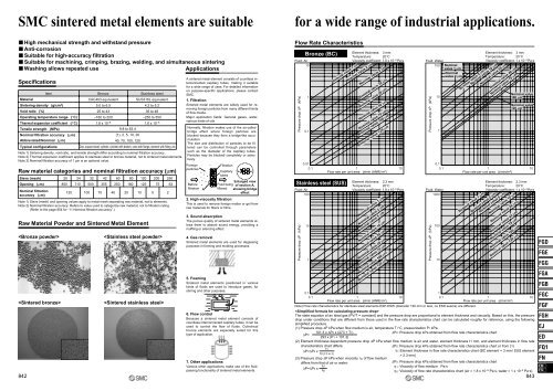
Flow Rate Characteristics<br />
Fluid: Air<br />
10<br />
Pressure drop ∆P (kPa)<br />
Pressure drop ∆P (kPa)<br />
1<br />
0.1<br />
0.01<br />
0.1 1 10<br />
Flow rate per unit area (l/min (ANR)/m 2 )<br />
Fluid: Air<br />
100<br />
Bronze (BC)<br />
Stainless steel (SUS)<br />
10<br />
1<br />
Nominal value 1 µm<br />
<strong>Element</strong> thickness: 3 mm<br />
Temperature: 20°C<br />
Viscosity coefficient: 1.8 x 10 –5 Pa·s<br />
Nominal value 2 µm<br />
Nominal value 5 µm<br />
Nominal value 10 µm<br />
Nominal value 20 µm<br />
Nominal value 40 µm<br />
Nominal value 70 µm<br />
Nominal value 100 µm<br />
Nominal value 120 µm<br />
<strong>Element</strong> thickness: 2.3 mm<br />
Temperature: 20°C<br />
Viscosity coefficient: 1.8 x 10 –5 Pa·s<br />
Nominal value 1 µm<br />
Nominal value 2 µm<br />
Nominal value 5 µm<br />
Nominal value 10 µm<br />
Nominal value 20 µm<br />
Nominal value 40 µm<br />
Nominal value 70 µm<br />
Nominal value 100 µm<br />
Nominal value 120 µm<br />
0.1<br />
0.1 1 10<br />
Flow rate per unit area (l/min (ANR)/m 2 )<br />
Fluid: Water<br />
100 Nominal<br />
value 1 µm<br />
Nominal<br />
value 2 µm<br />
Pressure drop ∆P (kPa)<br />
Pressure drop ∆P (kPa)<br />
10<br />
1<br />
0.1<br />
0.1 1 10<br />
Flow rate per unit area (l/min/m 2 )<br />
Fluid: Water<br />
1000<br />
100<br />
10<br />
Nominal value 10 µm<br />
Nominal value 5 µm<br />
Nominal value 1 µm<br />
Nominal value 20 µm<br />
Nominal value 2 µm<br />
<strong>Element</strong> thickness: 3 mm<br />
Temperature: 20°C<br />
Viscosity coefficient: 1 x 10 –3 Pa·s<br />
Nominal value 40 µm<br />
Nominal value 70 µm<br />
Nominal value 5 µm<br />
Nominal value 10 µm<br />
Nominal value 20 µm<br />
Nominal value 40 µm<br />
Nominal value 70 µm<br />
Nominal value 100 µm<br />
Nominal value 120 µm<br />
Nominal value<br />
100 µm<br />
Nominal value<br />
120 µm<br />
<strong>Element</strong> thickness: 2.3 mm<br />
Temperature: 20°C<br />
Viscosity coefficient: 1 x 10 –3 Pa·s<br />
1<br />
0.1 1 10<br />
Flow rate per unit area (l/min/m 2 )<br />
Note) Flow rate characteristics for stainless steel elements ESP-ESW (diameter 120 mm or less, no ESD seams) are different.<br />
<br />
The state equation of an ideal gas (PV/T = constant) and the pressure drop are proportional to element thickness and viscosity. Based on this, the pressure<br />
drop under conditions that are different from those used in the flow rate characteristics chart can be calculated roughly for reference, using the following<br />
simplified procedure.<br />
(1) Pressure drop ∆P kPa when flow medium is air, temperature T1°C, pressurization P1 kPa:<br />
101.3 x ∆P0 x (273 + T1)<br />
∆P0: Pressure drop kPa obtained from flow rate characteristics chart<br />
∆P=<br />
293 x (P1 + 101.3)<br />
(2) <strong>Element</strong> thickness dependent pressure drop ∆P kPa when flow medium is air and water, element thickness t1 mm, and element thickness in flow rate<br />
characteristics chart differs:<br />
∆P0: Pressure drop kPa obtained from flow rate characteristics chart or from (1)<br />
t1<br />
∆P=∆P0 x<br />
t0: <strong>Element</strong> thickness in flow rate characteristics chart (BC element = 3 mm/ SUS element<br />
t0 (2.3 or 3)<br />
= 2.3 mm)<br />
(3) Pressure drop ∆P kPa when viscosity η 1 of flow medium<br />
differs from that of air or water:<br />
η1<br />
∆P=∆P0 x<br />
η 0<br />
∆P0: Pressure drop kPa obtained from flow rate characteristics chart<br />
η 1 : Viscosity of flow medium Pa·s<br />
η 0 : Viscosity of flow rate characteristics chart (air = 1.8 x 10 –5 Pa·s, water = 1 x 10 –3 Pa·s)<br />
843<br />
FGD<br />
FGE<br />
FGG<br />
FGA<br />
FGB<br />
FGC<br />
FGF<br />
FGH<br />
EJ<br />
ED<br />
FQ1<br />
FN<br />
EB<br />
ES