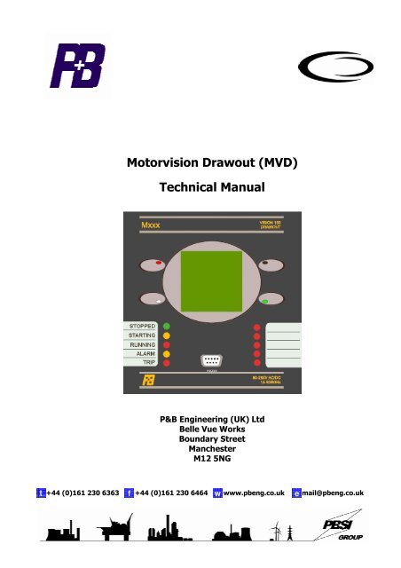
Motorvision Drawout (MVD) Technical Manual - PBSI Group Ltd
Motorvision Drawout (MVD) Technical Manual - PBSI Group Ltd
Motorvision Drawout (MVD) Technical Manual - PBSI Group Ltd

Create successful ePaper yourself
Turn your PDF publications into a flip-book with our unique Google optimized e-Paper software.
<strong>Motorvision</strong> <strong>Drawout</strong> (<strong>MVD</strong>)<br />
<strong>Technical</strong> <strong>Manual</strong><br />
P&B Engineering (UK) <strong>Ltd</strong><br />
Belle Vue Works<br />
Boundary Street<br />
Manchester<br />
M12 5NG<br />
t +44 (0)161 230 6363 f +44 (0)161 230 6464 w www.pbeng.co.uk e mail@pbeng.co.uk
<strong>MVD</strong> TECHNICAL MANUAL<br />
Contents<br />
1. P&B <strong>Motorvision</strong> <strong>Drawout</strong> (<strong>MVD</strong>). .......................................................................................................1<br />
1.1. PROTECTIVE FUNCTIONS. ......................................................................................................................................2<br />
1.2. DISPLAYED DRIVE DATA........................................................................................................................................2<br />
1.3. DISPLAYED DRIVE STATUS. ...................................................................................................................................3<br />
1.4. STARTING LOGIC...................................................................................................................................................3<br />
1.5. CONTROL FUNCTIONS............................................................................................................................................3<br />
1.6. CONTROL OUTPUT RELAYS. ...................................................................................................................................3<br />
1.7. CONTROL INPUTS..................................................................................................................................................3<br />
2. <strong>Technical</strong> Specification. .........................................................................................................................4<br />
3. Environmental Tests...............................................................................................................................5<br />
4. Analogue Inputs......................................................................................................................................6<br />
4.1. POWER SUPPLY.....................................................................................................................................................6<br />
4.2. VOLTAGE INPUTS. .................................................................................................................................................6<br />
4.3. CURRENT INPUTS..................................................................................................................................................6<br />
5. <strong>MVD</strong> Control Outputs..............................................................................................................................7<br />
6. <strong>MVD</strong> Control Inputs. ...............................................................................................................................9<br />
7. <strong>MVD</strong> Serial Ports. ..................................................................................................................................11<br />
7.1. RS485 ...............................................................................................................................................................11<br />
7.2. RS232 ...............................................................................................................................................................11<br />
8. Trip Circuit Supervision........................................................................................................................12<br />
9. <strong>MVD</strong> Faceplate Functions. ...................................................................................................................13<br />
9.1. LED STATUS.......................................................................................................................................................13<br />
10. Graphical Display................................................................................................................................13<br />
10. Graphical Display................................................................................................................................14<br />
10.1. MENU SCREENS. ...............................................................................................................................................14<br />
10.2. DISPLAY SCROLL...............................................................................................................................................15<br />
10.3. DATA MENU......................................................................................................................................................15<br />
10.3.1.1. Measured Values...............................................................................................................................16<br />
10.3.1.1.1 Inputs> Digital Values........................................................................................................................ 16<br />
10.3.1.1.2. Inputs> Analogue Values. ................................................................................................................ 16<br />
10.3.1.2. Disturb Values. ..................................................................................................................................16<br />
10.3.1.3. Start Data...........................................................................................................................................17<br />
10.3.1.3.1. Last Curve............................................................................................................................................... 17<br />
10.3.1.3.2. Start Values. .......................................................................................................................................... 17<br />
10.3.1.3.3. Reference Curve................................................................................................................................... 17<br />
10.3.2. Stats. ......................................................................................................................................................18<br />
10.3.3. Fault Data..............................................................................................................................................18<br />
10.3.3.1. Active Faults.............................................................................................................................................. 18<br />
10.3.3.2. Last Fault.................................................................................................................................................... 18<br />
10.3.3.2.1. Last Trip. ................................................................................................................................................ 19<br />
10.3.3.2.2. Last Alarm. ............................................................................................................................................. 19<br />
10.3.3.3. Fault History.............................................................................................................................................. 19<br />
10.3.3.3.1. Trip History. ........................................................................................................................................... 19<br />
10.3.3.3.2. Alarm History. ........................................................................................................................................ 19<br />
10.4. DRIVE CONTROL. ..............................................................................................................................................20<br />
10.5. SETTINGS MENU. ..............................................................................................................................................21<br />
10.5.1. Control Settings. ...................................................................................................................................21<br />
10.5.1.1. Starter Settings........................................................................................................................................ 21<br />
10.5.1.1.1. Start / Stop Source Settings. ............................................................................................................... 22<br />
10.5.1.2. Digital Inputs............................................................................................................................................ 22<br />
10.5.1.4. RELAY OUTPUTS.........................................................................................................................................23<br />
10.5.2. Protection Settings. ..............................................................................................................................24<br />
Issue 1 03/2008
<strong>MVD</strong> TECHNICAL MANUAL<br />
10.5.2.1. Protective Functions............................................................................................................................... 24<br />
10.5.3. System Settings....................................................................................................................................25<br />
10.5.3.1. Motor Settings.......................................................................................................................................... 25<br />
10.5.3.2. Serial Settings. ......................................................................................................................................... 25<br />
10.5.3.3. Unit Settings. ............................................................................................................................................ 26<br />
10.5.3.4. Smart Card Settings. .............................................................................................................................. 26<br />
11. Menu Tree Structure. .........................................................................................................................27<br />
12. <strong>MVD</strong> System Settings Summary. .....................................................................................................28<br />
13. <strong>MVD</strong> Control Setting Summary. .......................................................................................................29<br />
14. <strong>MVD</strong> Protection Setting Summary...................................................................................................30<br />
15. Serial Settings. ....................................................................................................................................31<br />
16. Motor Settings.....................................................................................................................................33<br />
17. Starting Methods. ...............................................................................................................................35<br />
18. Starter Settings...................................................................................................................................38<br />
18.1. ADDITIONAL STARTER SETTINGS.......................................................................................................................40<br />
19. Protection Settings.............................................................................................................................41<br />
19.1. PROTECTION FUNCTIONS. .................................................................................................................................43<br />
19.1.1. Maximum Start Time............................................................................................................................43<br />
19.1.2. Thermal Model......................................................................................................................................43<br />
19.1.3. Undercurrent.........................................................................................................................................45<br />
19.1.4. Load Increase. ......................................................................................................................................46<br />
19.1.5. Overcurrent. ..........................................................................................................................................46<br />
19.1.6. Over Frequency. ...................................................................................................................................46<br />
19.1.7. Under Frequency. .................................................................................................................................47<br />
19.1.8. Single Phase..........................................................................................................................................47<br />
19.1.9. Phase Rotation......................................................................................................................................47<br />
19.1.10. Unbalance Current. ............................................................................................................................47<br />
19.1.11. Undervoltage.......................................................................................................................................48<br />
19.1.12. U/V Lockout. .......................................................................................................................................48<br />
19.1.13. Earth Fault...........................................................................................................................................48<br />
19.1.14. Too Many Starts. ................................................................................................................................49<br />
19.1.16. Overvoltage.........................................................................................................................................50<br />
19.1.17. Backspin. .............................................................................................................................................50<br />
19.1.18. Power Factor.......................................................................................................................................50<br />
19.1.19. External 1 to 10..................................................................................................................................51<br />
19.1.20. Short Circuit. .......................................................................................................................................51<br />
19.1.21. Contactor Fault. ..................................................................................................................................51<br />
19.1.22. Emergency Stop. ................................................................................................................................52<br />
19.1.23. Serial Timeout.....................................................................................................................................52<br />
19.1.24. Internal Error. .....................................................................................................................................52<br />
19.1.25. Serial Inhibit........................................................................................................................................52<br />
20. Unit Settings. .......................................................................................................................................53<br />
21. Smart Card Settings. ..........................................................................................................................55<br />
22. Disturbance Recording. .....................................................................................................................57<br />
Appendix 1 ..................................................................................................................................................59<br />
<strong>MVD</strong> Installation........................................................................................................................................59<br />
Appendix 2 ..................................................................................................................................................61<br />
Termination Numbers...............................................................................................................................61<br />
Appendix 3 ..................................................................................................................................................62<br />
<strong>MVD</strong> Schematic Diagrams........................................................................................................................62<br />
Appendix 4 ..................................................................................................................................................64<br />
Thermal Overload Trip Times. .................................................................................................................64<br />
Appendix 5 ..................................................................................................................................................65<br />
Fast Scan Values........................................................................................................................................65<br />
Appendix 6 ..................................................................................................................................................66<br />
Equipment Disposal. .................................................................................................................................66<br />
Issue 1 03/2008
<strong>MVD</strong> TECHNICAL MANUAL<br />
1. P&B <strong>Motorvision</strong> <strong>Drawout</strong> (<strong>MVD</strong>).<br />
P&B Engineering's <strong>MVD</strong> is a highly sophisticated microprocessor based motor protection and<br />
control unit, specifically designed to be used as an integral part of any type or manufacture of<br />
Motor Control Centre. <strong>MVD</strong> provides total control, protection and monitoring of LV and MV<br />
motor starters either by direct hard wired inputs and / or via the serial ports with 1ms time<br />
stamping of events.<br />
The <strong>MVD</strong> fundamentally is an intelligent overload device for protection of 3-phase medium<br />
voltage motors. It also controls the switching mechanism and can be used to control Direct On<br />
Line, Star-Delta 2 & 3, Direct On Line Reversing, Air Circuit Breaker, DOL with Heater, Two<br />
Speed and Variable Speed Drive motor starters.<br />
<strong>MVD</strong> monitors the current and voltage to provide a comprehensive motor protection package.<br />
This is combined with all the necessary control and monitoring functions and a high-speed<br />
communication facility. The unit is a small, easily installed package supplied at a very<br />
competitive cost which makes <strong>MVD</strong> the most attractive Motor Protection and Control device<br />
available today.<br />
All hard-wired control inputs are connected to the device via optically isolated inputs to enable<br />
all starting, stopping and tripping commands to be carried out by the unit. The status of all<br />
individual hard-wired contacts is also provided both locally via the liquid crystal display and<br />
remotely via any of the communication ports.<br />
All Setting parameters are programmed independently for each unit via the integral keypad and<br />
liquid crystal display on the front plate or via any of the communication ports and PC based<br />
software package available for the Vision II series of products.<br />
During operation the LCD also gives access to accurate running, statistical and fault data such<br />
as; Volts, Phase Amps, Thermal Capacity, Time to Trip, Phase Unbalance, Motor Hours Run<br />
and Number of Starts with separate counters for forward/reverse or high/low speed operations.<br />
Light Emitting Diodes mounted on the front plate give visual indication of the motor status i.e.<br />
ON / INHIBIT / OFF and ALARM / FAULTY / HEALTHY and other programmable conditions.<br />
Flexible high speed control via PLC or DCS systems is obtained through the <strong>MVD</strong>’s<br />
communication ports, allowing computer access to full control and monitoring of motor data,<br />
including: running data, motor statistical data and control input status.<br />
P&B Engineering Issue 1 03/2008 Page 1
<strong>MVD</strong> TECHNICAL MANUAL<br />
1.1. Protective Functions.<br />
Max Start Time Protection<br />
Thermal Overload Protection with adjustable t6x and hot/cold ratio and fixed pre alarm<br />
Undercurrent Protection<br />
Load Increase Protection<br />
Low Set Overcurrent Protection<br />
Overfrequency Protection<br />
Underfrequency Protection<br />
Single Phase Protection<br />
Phase Rotation Protection<br />
Phase Unbalance Protection<br />
Undervoltage Protection<br />
Undervoltage Start Lockout<br />
Earth Fault Protection<br />
Excess Number of Starts Protection<br />
Overvoltage Protection<br />
Backspin Protection<br />
Power Factor Protection<br />
Short Circuit Protection<br />
Contactor Fault Protection<br />
Emergency Stop Protection<br />
Serial Timeout Protection<br />
Internal Error Protection<br />
Serial Inhibit Protection<br />
10 External Semi-Customised Digital Inputs<br />
Configurable 2 Channel Trip Circuit Supervision Protection (Optional)<br />
1.2. Displayed Drive Data.<br />
Phase & Average Amps<br />
Last Start Data<br />
Earth Fault Current<br />
Number of Trips<br />
Percentage Unbalance<br />
Total Operations, Start A<br />
Percentage Motor Load<br />
Total Operations, Start B<br />
3 Phase Voltage k(M/G/T)W Hours<br />
Percentage Thermal Capacity<br />
k(M/G/T)VA Hours<br />
Motor Status<br />
k(M/G/T)W Max Demand<br />
Power k(M/G/T)W<br />
k(M/G/T)VA Apparent Power<br />
Power Factor<br />
k(M/G/T)VAr Real Power<br />
Running Status<br />
Last Stop Source with time and date<br />
Frequency<br />
Time to Reaccelerate<br />
Time & Date<br />
Time to Clear Inhibit<br />
Hours Run<br />
Last Peak I<br />
Hours Run This Start<br />
Last Start Source with time and date<br />
Reference Start Curve (graphic)<br />
Last Start Curve (graphic)<br />
Start Curve (graphic)<br />
Time to Trip<br />
Time to Reset<br />
Page 2 Issue 1 03/2008 P&B Engineering
<strong>MVD</strong> TECHNICAL MANUAL<br />
1.3. Displayed Drive Status.<br />
Running / Starting / Stopped / Inhibit<br />
Forward / Reverse / Two Speed / Star/Delta<br />
Alarm Description, Pre- Trip Values, Alarm History<br />
Trip Description, Pre- Trip Values, Trip History<br />
Auto / <strong>Manual</strong> Mode<br />
Local / Remote Mode<br />
1.4. Starting Logic.<br />
Direct-on-Line<br />
Reversing Direct-on-Line<br />
2 Speed (separate winding and tapped winding motors)<br />
DOW 2 Speed (as above, also allows speed transition without stopping)<br />
Star/Delta 2<br />
Star/Delta 3 (includes line contactor)<br />
ACB (mechanically latched contactor)<br />
Direct-on-Line Heater (with a facility to inject winding heating supply)<br />
Reversing Direct-on-Line Heater (with a facility to inject winding heating supply)<br />
Variable Speed Drive<br />
1.5. Control Functions.<br />
Via Hardwired inputs:<br />
Start, Stop, Reset,<br />
Local/Remote Select, Auto/<strong>Manual</strong> Select<br />
Via Comms input:<br />
Start, Stop, Reset, Set/Clear Inhibit<br />
1.6. Control Output Relays.<br />
Via Keypad:<br />
Start, Stop, Reset,<br />
Local/Remote and Auto/<strong>Manual</strong> select∗<br />
Only if L/R, A/M are not configured as hardwired inputs∗<br />
Output Relay #1, Output Relay #2, Output Relay #3, Output Relay #4<br />
Some of the Output Relays are pre-set depending on the Starter Type chosen. Others can be<br />
programmed by the user. They can be programmed as follows: -<br />
Not Used, Follow A, Follow B, Inv A, Inv B, Trip, Trip FS, Alarm, Alarm FS, Healthy, Warning,<br />
Serial-Available, Panel-Available, Remote-Available, Health FS, Indicator 1, Indictor 2, Indicator<br />
3, Indicator 4, Indicator 5.<br />
1.7. Control Inputs.<br />
The user can define the function of the twelve optically isolated inputs from the list below.<br />
1. Not Used 9. Reset Fault 17. External Fault 4<br />
2. Start A 10. Auto / <strong>Manual</strong> 18. External Fault 5.<br />
3. Start B 11. Local / Remote 19. External Fault 6<br />
4. Stop 12. Speed Switch 20. External Fault 7<br />
5. E Stop 13. Authorise 21. External Fault 8<br />
6. Contactor A 14. External Fault 1 22. External Fault 9<br />
7. Contactor B 15. External Fault 2 23. External Fault 10<br />
8. Test 16. External Fault 3 24. Restart<br />
P&B Engineering Issue 1 03/2008 Page 3
<strong>MVD</strong> TECHNICAL MANUAL<br />
2. <strong>Technical</strong> Specification.<br />
Power Supply.<br />
Auxiliary Power Supply & Low Voltage Power Supply<br />
AC Nominal<br />
Range 80 – 265V AC / DC<br />
Range 24V AC / 24-48V DC (Low Voltage Power Supply Optional Extra)<br />
Frequency<br />
45 - 65 Hz<br />
Maximum Power Consumption<br />
10VA, 15VA Nominal<br />
Measurement.<br />
Phase Current Measurement<br />
Method<br />
Range<br />
Full Scale<br />
Accuracy<br />
Earth Phase Current Measurement<br />
Method<br />
Range<br />
True RMS, Sample time
<strong>MVD</strong> TECHNICAL MANUAL<br />
3. Environmental Tests.<br />
CLIMATIC TEST STANDARD SEVERITY LEVEL<br />
Temperature Dry Cold<br />
IEC 60068-2-1 -20 deg C ,96 hrs<br />
Operational<br />
Temperature Dry Cold<br />
Transportation & Storage<br />
IEC 60068-2-1 -40 deg C , 96hrs<br />
Temperature Dry Heat<br />
Operational<br />
Temperature Dry Heat<br />
Transportation & Storage<br />
IEC 60068-2-2<br />
IEC 60068-2-2<br />
+60 deg C , 96 hrs<br />
+85 deg C , 96 hrs<br />
Damp Heat<br />
IEC 60068-2-30 95% Non-condensing, Cyclic Test Db<br />
Steady State<br />
Enclosure IEC 60529 front IP52 , rear IP00<br />
MECHANICAL<br />
Vibration IEC 60255-21-1 Class I<br />
Shock & Bump IEC 60255-21-2 Class I<br />
Seismic IEC 60255-21-3 Class I<br />
ELECTRICAL<br />
Insulation resistance IEC 60255-5 500 Vdc , 5 secs<br />
Dielectric Test IEC 60255-5 Series C of table 1<br />
2.5 kV 50Hz , 1 min<br />
1.0 kV open contacts , 1 min<br />
High Voltage Impulse IEC 60255-5 5 kV peak 1.2/50uS,0.5J<br />
3 pos , 3 neg<br />
Voltage Dips , Short<br />
Interruptions & Voltage<br />
IEC 60255-11<br />
IEC 61000-4-11<br />
3 dips & 3 interruptions at 10 sec intervals of duration between<br />
10mS and 500mS at zero crossings. Variations 40% &70%<br />
variations immunity<br />
Ripple in dc supply IEC 60255-11 12% ac ripple<br />
VT input Thermal Withstand<br />
120% Vn , continuous<br />
CT input Thermal Withstand 250xIn half wave,100xIn for 1 second 30 xIn for 10 second ,<br />
4 xIn cont.<br />
ELECTROMAGNETIC COMPATIBILITY<br />
Electrical fast Transient/Burst IEC 60255-22-4<br />
IEC 61000-4-4<br />
Oscillatory Waves<br />
1 Mhz Burst<br />
IEC 60255-22-1<br />
Class IV-4.0kv Power supply<br />
Class III -2.0 kV Other inputs<br />
1 min each polarity<br />
Class III<br />
Longitudinal 2.5 kV , 2sec<br />
Transverse 1.0 kV , 2 sec<br />
Electrostatic Discharge IEC 60255-22-2 Class III<br />
8 kV contact 15kV air discharge , 10 discharges at 1 sec intervals<br />
Conducted Disturbance<br />
RF fields<br />
IEC 61000-4-6 0.15 to 80 Mhz<br />
Severity Level 10Vrms<br />
+sweeps 0.05-0.15MHz & 80-100MHz<br />
Radiated e-m field<br />
from digital portable telephones<br />
ENV 50204 900 & 1890mhz at 10V/m<br />
Radiated RF e-m field immunity<br />
test<br />
IEC 60255-22-3<br />
ClassIII test method A<br />
+sweep 500-1000mhz<br />
or IEC 1000-4-3 80-1000mhz<br />
severity 10V/m 80% modulated 1 kHz<br />
Surge Immunity IEC 61000-4-5 4kV common mode<br />
2kV differential mode , 1.2/50uS<br />
Power Frequency Magnetic<br />
Field<br />
IEC 61000-4-8 1000A/m for 1 sec<br />
100A/m for 1 minute<br />
Pulse Magnetic Field IEC 61000-4-9 6.4/16uS , 1000A/m<br />
Damped Oscillatory Magnetic IEC 61000-4-10 0.1 & 1.0 Mhz , 100A/m<br />
Field Immunity<br />
Conducted & Radiated RF<br />
Interference Emission<br />
EN55022 or<br />
EN55011or<br />
EN50081-2<br />
Class A interference limits<br />
Power frequency conducted<br />
immunity, common mode<br />
IEC 61000-4-16<br />
IEC 60255-22-7<br />
DC to 150kHz sweep test level 4<br />
300V at 16 2/3 & 50/60Hz<br />
P&B Engineering Issue 1 03/2008 Page 5
<strong>MVD</strong> TECHNICAL MANUAL<br />
4. Analogue Inputs.<br />
4.1. Power Supply.<br />
The <strong>MVD</strong> requires an AC or DC Voltage to supply the unit.<br />
In order to energise a digital input the terminal should be powered by a voltage which is both<br />
the same phase and magnitude as the live connection of the auxiliary supply.<br />
4.2. Voltage Inputs.<br />
The <strong>MVD</strong> monitors three phase voltage, which can be directly connected for voltages up to<br />
500V.<br />
With the use of Voltage Transformer the <strong>MVD</strong> can monitor voltages up to 22kV.<br />
4.3. Current Inputs.<br />
Normally, the <strong>MVD</strong> has provision to allow connection of standard 1 amp or 5 amp secondary<br />
current transformers. The Earth fault measurement can either be a residual connection from the<br />
three phase CT’s, via a CBCT, or by means of a special internally calculated residual earth<br />
fault.<br />
Page 6 Issue 1 03/2008 P&B Engineering
<strong>MVD</strong> TECHNICAL MANUAL<br />
5. <strong>MVD</strong> Control Outputs.<br />
The <strong>MVD</strong> has 4 output relays which can be assigned as follows depending on the type of<br />
starter that the motor is connected to.<br />
STARTER TYPE OUTPUT RELAY<br />
RELAY 1 RELAY 2 RELAY 3 RELAY 4<br />
DOL RUN Programmable Programmable Programmable<br />
S/D 2 STAR DELTA Programmable Programmable<br />
S/D 3 STAR DELTA LINE Programmable<br />
DOLR FORWARD REVERSE Programmable Programmable<br />
2 Speed LOW HIGH Programmable Programmable<br />
DOW 2 Speed LOW HIGH Programmable Programmable<br />
ACB CLOSE OPEN Programmable Programmable<br />
DOLH RUN HEATER Programmable Programmable<br />
DOLRH FORWARD REVERSE HEATER Programmable<br />
VSD RUN Programmable Programmable Programmable<br />
Where stated the corresponding output relays can be programmed with the following options:-<br />
Follow A.<br />
If an output relay is programmed as ‘Follow A’ its state will mirror the state of output relay 1.<br />
When a relay is programmed as ‘Follow A’ a delay may be assigned.<br />
Follow B.<br />
If an output relay is programmed as ‘Follow B’ its state will mirror the state of output relay 2.<br />
When a relay is programmed as ‘Follow B’ a delay may be assigned.<br />
Inverse A.<br />
If an output relay is assigned as ‘Inv. A’ its state will always be the inverse of the state of output<br />
relay 1.<br />
Inverse B.<br />
If an output relay is assigned as ‘Inv. B’ its state will always be the inverse of the state of output<br />
relay 2.<br />
Trip.<br />
If an output relay is assigned as ‘Trip’ then this relay will change state from the de-energised to<br />
the energised relay contact when triggered by any protection function or external device<br />
connected to the relay that is configured to trip the motor.<br />
Trip Fail Safe.<br />
If an output relay is assigned as ‘Trip FS’ (Trip Failsafe) then this relay will change state from<br />
energised to the de-energised relay contact when triggered by any protection function or<br />
external device connected to the relay that is configured to trip the motor.<br />
Alarm.<br />
If an output relay is assigned as ‘Alarm’ then this relay will change state from de-energised to<br />
the energised relay contact when triggered by any protection function or external device<br />
connected to the relay that is configured to alarm.<br />
Alarm Fail Safe.<br />
If an output relay is assigned as ‘Alarm FS’ then this relay will change state from energised to<br />
the de-energised relay contact when triggered by any protection function or external device<br />
connected to the relay that is configured to alarm.<br />
P&B Engineering Issue 1 03/2008 Page 7
<strong>MVD</strong> TECHNICAL MANUAL<br />
Healthy.<br />
If an output relay is assigned as ‘Healthy’ this relay will be in its de-energised state at all times<br />
while the unit reports the motor as being healthy. This relay will be energised when the unit<br />
registers either an Alarm or Fault condition or the motor has been inhibited from starting.<br />
Warning.<br />
If an output relay is assigned as ‘Warning’ then it will change state when any enabled protection<br />
function has exceeded its pickup value.<br />
The relay is not latching. When the pickup setting is no longer violated the output relay<br />
assigned as ‘Warning’ will be de-energised. The ‘Warning’ relay does not wait until the expiry of<br />
a trip or alarm timer before being energised. It will energise immediately after an enabled<br />
protection feature has its pickup point violated or a digital input registers a fault status.<br />
Serial Available.<br />
If an output relay is assigned as ‘Serial Available’ this relay will be energised only when the<br />
motor is available to be started through the serial port, via a serial command. For details on<br />
configuring possible start sources see sections10.5.1.1.1 and 17.<br />
Panel Available.<br />
If an output relay is assigned as “Panel Available” this relay will be energised only when the<br />
motor is available to be started from the front panel of the relay. For details on configuring<br />
possible start sources see sections 10.5.1.1.1 and 17.<br />
Remote Available.<br />
If an output relay is assigned as ‘Remote Available’ this relay will be energised only when the<br />
motor is available to be started from a remote station via a digital input. For details on<br />
configuring possible start sources see sections 10.5.1.1.1 and 17.<br />
Healthy Fail Safe.<br />
If an output relay is assigned as ‘Healthy FS’ (Healthy Failsafe) this relay will be in its energised<br />
state at all times while the unit reports the motor as being healthy. This relay will be deenergised<br />
when the unit registers either an Alarm or Fault condition or the motor has been<br />
inhibited from starting.<br />
Indicator 1-5.<br />
If an output relay is assigned as any of the 5 available Indicators then this relay will change<br />
state from de-energised to the energised relay contact when triggered by any protection<br />
function or external device connected to the relay that is configured to indicate on that same<br />
indicator channel.<br />
An Indicator relay will only be energised following the expiry of the delay timer (if a delay is<br />
assigned) for a protection function or external device that registers its pickup setting or fault<br />
status has been violated. When the pickup setting or fault status is no longer violated the output<br />
relay assigned to the relevant Indicator will be de-energised. An Indicator is not latched.<br />
Typically these are used for single function signaling or used as output indicators to other drives<br />
when forming part of a hardwired permissive control system.<br />
Page 8 Issue 1 03/2008 P&B Engineering
<strong>MVD</strong> TECHNICAL MANUAL<br />
6. <strong>MVD</strong> Control Inputs.<br />
The <strong>MVD</strong> offers 12 digital inputs to provide full control and indication for the motor starter. The<br />
supply to these terminals is internally derived from the auxiliary supply which is used to power<br />
the unit.<br />
In order to energise a digital input the terminal should be powered by a voltage which is both<br />
the same phase and magnitude as the live connection.<br />
The condition of all these inputs can be viewed at any time via the Digital Inputs page of the<br />
Data Menu which enables complete wire checking without the need to disconnect or even gain<br />
access to the rear panel wiring.<br />
The 12 inputs are chosen by the user from the list described in the following sections.<br />
Start A and Start B Inputs.<br />
When one of these inputs are closed the corresponding output relay is energised as long as the<br />
Start Setup Sources has been set accordingly (see sections 10.5.1.1.1 and 17), and provided<br />
all other External Faults are in the healthy state. Start A only is used for DOL, DOL Forward,<br />
Star or Low Speed contactors whilst Start B is used for DOL Reverse or High Speed. The<br />
starter settings menu allows these Start inputs to be either momentary, i.e. from push buttons<br />
or maintained, i.e. from PLC outputs not both.<br />
Stop Input.<br />
If this input is open circuited the motor will be switched off and inhibited from starting as long as<br />
the Stop Setup Sources have been set to allow the stop to be active from the remote source.<br />
see sections 10.5.1.1.1 and 17.<br />
Emergency Stop.<br />
This input allows the <strong>MVD</strong> to monitor the status and provide indication of the state of any of the<br />
external Emergency Stop buttons which are normally directly wired to the contactor closing<br />
circuit. Opening of the input causes a trip with an option to alarm depending on the Protection<br />
Settings. Emergency Stop is only disabled when used for contactor applications, (short circuit<br />
protection is also disabled) when the phase fault current exceeds 9x In.<br />
Contactor A and B Status.<br />
These status inputs from the contactors allow the <strong>MVD</strong> to determine and show via the front<br />
plate LED's and LCD display the status of both the A and B contactors, also known as Relays 1<br />
and 2. Cont A is the feedback signal for a Start A command and Cont B is the feedback signal<br />
for a Start B command.<br />
Monitoring of these contacts also provides protection against 'Control Open' (when a <strong>MVD</strong><br />
START command is not confirmed by these inputs, Cont A and/or Cont B) and 'Welded<br />
Contact' (when <strong>MVD</strong> STOP command is not confirmed by these inputs). Only when the<br />
Contactor Fault protection is enabled do these ‘active faults’ appear under warranted situations.<br />
Test Mode.<br />
When in the Test mode the <strong>MVD</strong> will disable Undercurrent Protection, Undervoltage, Single<br />
Phase and Phase Sequence protection functions, as well as the External Faults if set to Disable<br />
in Test.<br />
This allows full functional testing to be performed without the need for voltage or current<br />
injection and will allow secondary injection testing to be carried out on all protective functions<br />
except for those disabled by the feature.<br />
P&B Engineering Issue 1 03/2008 Page 9
<strong>MVD</strong> TECHNICAL MANUAL<br />
Reset Fault.<br />
This input enables the operator to reset <strong>MVD</strong> Fault or Alarm conditions. The Input can only<br />
perform a reset if the following conditions are met:<br />
1. The Protection Settings for the specific fault or alarm are set to allow remote resets.<br />
2. The condition that caused the Fault or Alarm to occur no longer exists.<br />
Providing conditions 2 and 3 are met an operator can override the settings in the Protection<br />
Settings by closing the Authorise digital input and pressing the Reset digital input.<br />
Auto/<strong>Manual</strong> and Local/Remote Inputs.<br />
These inputs are used to determine the source of both the Start Signal and Stop Signal to the<br />
motor. They are configured in the Start Setup Source and the Stop Setup Source. see sections<br />
10.5.1.1.1 and 17.<br />
Speed Switch.<br />
Closing of this input reduces the trip time on the cold and hot curves by 50%. A tachometer is<br />
generally used on the rotor to determine if the shaft is turning the transducer is fed to this input.<br />
This provides a faster trip for stalled motors.<br />
Authorise.<br />
This function can be programmed as a digital input to allow a physical key switch to override the<br />
password and reset all faults. This input can be used to restrict fault and alarm reset, if the Auto<br />
and Panel reset options of protective functions are disabled a fault can only be reset from the<br />
panel if the authorised input is closed. The use of the "Authorise" function will override the<br />
password. All data menus, display scroll and drive control are accessible without requiring the<br />
use of the "Authorise" or "Password" functions if these are enabled.<br />
Should a digital input be set to Authorise then the user will be unable to Disable the Password<br />
Setting on the relay. To Disable the password the Authorise input must be assigned as another<br />
digital input or set to ‘Not Used’.<br />
External Faults 1-10.<br />
The flexibility of the External Fault inputs gives <strong>MVD</strong> an intelligent PLC aspect to protective<br />
relaying.<br />
External Faults are voltage based and are assigned to digital inputs to perform a wide variety of<br />
roles. Multiple plant interlocking, process shutdown or for use as a gateway onto the serial<br />
network for digital signals via the <strong>MVD</strong>.<br />
External Faults can be configured as independent protective functions and can be configured to<br />
any combination of; Trip, Alarm, Inhibit or just to Stop the drive. The normal reset types are<br />
available; Auto, Panel, Serial and Remote. Any combination of 5 indicators can be used to drive<br />
output relays configured to the same Indicator function.<br />
The fault status of the input is programmable such that OFF = Fault or ON = Fault where the<br />
input is fed from either a normally closed (NC) or normally open (NO) source.<br />
The trip time (or time to take the configured action) is settable in the range 1 to 60 seconds.<br />
Each External Fault text string (EXTERNAL 1 etc) can be reconfigured to any character and<br />
numerical string desired via the keypad (Unit Settings > Edit Custom Strings) or via any of the<br />
serial ports.<br />
Restart.<br />
This input will inhibit or permit an Undervoltage Restart to take place. This is to allow the<br />
differentiation between power losses that would and would not allow an automated restart of<br />
the drive. If the input is closed a restart can occur and if the input is open then the restart will be<br />
blocked. If no digital input is set to Restart then an Undervoltage Restart would always occur, if<br />
enabled. See section 17.<br />
Page 10 Issue 1 03/2008 P&B Engineering
<strong>MVD</strong> TECHNICAL MANUAL<br />
7. <strong>MVD</strong> Serial Ports.<br />
7.1. RS485<br />
The Serial Port supplied with <strong>MVD</strong> as standard utilises a half duplex RS485 protocol allowing<br />
up to 32 units to be daisy-chained together with a single shielded twisted pair cable.<br />
The <strong>MVD</strong> in addition to its very comprehensive protection and control features has been<br />
equipped with a very powerful data communications system. This extends its boundaries far<br />
beyond a motor protection controller into the realms of a complete motor management system.<br />
It provides high-speed data acquisition to supervisory computers to form a complete motor<br />
management system.<br />
Each <strong>MVD</strong> can be connected to an isolated data highway using RS485 communications. Up to<br />
32 units can be connected to each data highway. The host system can interrogate the unit to<br />
monitor motor status, running conditions, historical data and fault data as well as control<br />
functions such as a start and stop to the motor and reset fault / alarm conditions.<br />
The <strong>MVD</strong> is available with P&B network gold (P&B protocol) installed for use with the Xcell Data<br />
Concentrator for fully Integrated Protection, Control & Monitoring Systems with full dual<br />
redundancy or with a Slave implementation of Modbus RTU protocol for small systems and<br />
direct Modbus access to devices where data concentration is not required.<br />
7.2. RS232<br />
The front RS232 port is fitted as standard allowing access to historical and running data without<br />
disturbing the rear RS485 network. The front mounted serial port also allows the unit to be<br />
programmed and disturbance recording traces can be extracted online<br />
Full details of the protocols, device mapping, and other support documents are available on<br />
request.<br />
Information on the Xcell Data Concentrator is contained in the P&B Integrated Protection &<br />
Control System Integrators <strong>Manual</strong>, available on request.<br />
P&B Engineering Issue 1 03/2008 Page 11
<strong>MVD</strong> TECHNICAL MANUAL<br />
8. Trip Circuit Supervision.<br />
Trip Circuit Supervision is available as an option to the <strong>MVD</strong>.<br />
The trip circuit passes through external components such as fuses, links, relay contacts,<br />
auxiliary switch contact and others. Errors in any of these external components could lead to a<br />
trip not being called and the breaker remaining closed.<br />
TCS protection is normally applied to breaker controlled Motor Starters.<br />
To protect against these failures the <strong>MVD</strong> has two trip circuit supervision input circuits, one to<br />
monitor the trip relay and one to monitor the circuit breaker. Should they both read the same<br />
input, i.e. a trip has been called and the breaker is closed, the assigned output relay changes<br />
state.<br />
TYPICAL CONNECTIONS FOR SUPERVISION ELEMENTS<br />
+ve<br />
EXTRA CONTACTS<br />
IN PARALLEL<br />
-ve<br />
TRIP CONTACT(S)<br />
CB AUX SWITCH<br />
TRIP COIL<br />
TC<br />
TCS 1 TCS 2<br />
50 51<br />
ADVANCED MOTORVISION2<br />
52 53<br />
TRIP CIRCUIT SUPERVISION (TCS)<br />
The TCS element consists of two input circuits and two dedicated change-over contact output<br />
relays operating in tandem. As the TCS board does not interact with the main relay processor<br />
one of the digital outputs provided by the Trip Circuit Supervision should be fed back into the<br />
A<strong>MVD</strong>, as an External Fault input configured to alarm and / or inhibit. The other output can be<br />
used to drive an indication lamp for example.<br />
The Trip Circuit Supervision Output Relays are Fail Safe, this means that on power up the<br />
relays change state. Therefore in the situation where power is lost to the <strong>MVD</strong> an indication is<br />
given through the Trip Circuit.<br />
The output relays will enter an unhealthy state if one or both of the TCS Inputs are closed or if<br />
power is lost to the relay. The relays will only go back to a healthy state if both the inputs are<br />
open. The voltage supply to the elements can be either AC or DC within the range of the normal<br />
Aux. Supply (80-265 V AC/DC).<br />
Page 12 Issue 1 03/2008 P&B Engineering
<strong>MVD</strong> TECHNICAL MANUAL<br />
9. <strong>MVD</strong> Faceplate Functions.<br />
The <strong>MVD</strong> Faceplate has been designed to provide display and access to all the required<br />
information an operator may require.<br />
This is achieved by using a fully graphic LCD display, 4 software driven function keys and 10<br />
semi-programmable LEDs.<br />
This eliminates the need for additional indication devices on the front of the motor starter panel<br />
such as Lamps, Ammeter, Voltmeter, Hours Run Indicator, Operations Counter, etc. which can<br />
help reduce the cost of the motor starter panel and give improved reliability by the reduction of<br />
separate components.<br />
The display of the standard <strong>MVD</strong> can be found on the front page of this manual.<br />
9.1. LED Status.<br />
The LED's operate as follows:<br />
LED<br />
[Designation]<br />
LED<br />
[Colour]<br />
LED<br />
[Function]<br />
1 GREEN STOPPED<br />
2 ORANGE STARTING<br />
3 RED RUNNING<br />
4 ORANGE ALARM<br />
5 RED TRIP<br />
6 RED Programmable<br />
7 RED Programmable<br />
8 RED Programmable<br />
9 RED Programmable<br />
10 RED Programmable<br />
Programmable LEDs can be assigned to the activation of a particular protective function so that<br />
once a function has timed out the associated LED will illuminate until the specific fault is reset.<br />
LEDs 1 to 5 are pre set and specific to the <strong>MVD</strong> function.<br />
Programmable LEDs can be assigned for a drop down list menu, only a single be assigned to a<br />
protective function.<br />
LED 1<br />
LED 2<br />
LED 3<br />
LED 4<br />
LED 5<br />
LED 6<br />
UP<br />
SELECT<br />
LED Outputs<br />
STOPPED<br />
STARTING<br />
RUNNING<br />
ALARM<br />
TRIP<br />
Undervoltage<br />
Maximum Start<br />
Thermal<br />
Overcurrent<br />
Undercurrent<br />
Earth Fault<br />
Too Many Starts<br />
Undervoltage<br />
DOWN<br />
EXIT<br />
P&B Engineering Issue 1 03/2008 Page 13
<strong>MVD</strong> TECHNICAL MANUAL<br />
10. Graphical Display.<br />
The <strong>MVD</strong>’s graphical display is fundamental to the philosophy of the Vision IED family of<br />
devices. The screen provides access to all dynamic and historical data, protection parameter<br />
set points and control set-up.<br />
10.1. Menu Screens.<br />
MVII<br />
P+B VISION<br />
PROTECTION AND CONTROL<br />
V 1.111<br />
01/01/2004 13.00PM<br />
9999<br />
DATA<br />
MENU<br />
DRIVE<br />
CONTROL<br />
MOTOR TAG<br />
DISPLAY<br />
SCROLL<br />
Ave RMS Current<br />
0.00 A<br />
'FAULT' ...TRIP IN xxx S BANNER<br />
MESSAGE BANNER<br />
SETTINGS<br />
MENU<br />
On power up the <strong>MVD</strong> screen appears for a few seconds. The screen shows the software<br />
version and the unit serial number, which should be noted in all correspondence with P&B<br />
regarding the relay.<br />
After the Introduction screen disappears then the Initial screen appears.<br />
The main portion of the screen shows the main dynamic data of the drive, various message<br />
banners can appear under different conditions to alert the operator to the present conditions.<br />
These can be time to trip messages, countdown to restart message, countdown to reset or<br />
clear inhibit messages and so on. The name of the fault condition causing the trip will also<br />
appear along with the timer.<br />
The four menu driven software keys each navigate to four main areas of the menu structure.<br />
These are DISPLAY SCROLL, DATA MENU, DRIVE CONTROL and the SETTINGS MENU.<br />
Using soft-keys provides a very easy to use environment in order to effectively navigate the<br />
entire menu system.<br />
The DISPLAY SCROLL button scrolls in a loop displaying various measured values and drive<br />
status data. Any one of these pages can be selected as the ‘default’ page, so that if the unit is<br />
left whilst in a sub menu the screen can return to a pre-selected page after a set time-out<br />
period.<br />
Average RMS Current(A) Motor Running Status: (Stopped / Starting / Running / Inhibit)<br />
Separate 3-Phase Currents (A) and Fault Status: (Healthy / Fault / Alarm)<br />
Earth (ground) Current (A) Unbalance Current(%)<br />
Motor Load (%) and Thermal Capacity (%) Frequency (Hz)<br />
Voltage (V) Time and Date<br />
Temperature (single input) Starter Mimic<br />
Power (k/M/G or TW) and Power Factor<br />
Page 14 Issue 1 03/2008 P&B Engineering
<strong>MVD</strong> TECHNICAL MANUAL<br />
10.2. Display Scroll.<br />
DATA<br />
MENU<br />
DISPLAY<br />
SCROLL<br />
DATA<br />
MENU<br />
DISPLAY<br />
SCROLL<br />
DATA<br />
MENU<br />
DISPLAY<br />
SCROLL<br />
DATA<br />
MENU<br />
DISPLAY<br />
SCROLL<br />
MOTOR TAG<br />
Ave RMS Current<br />
0.00A<br />
MOTOR TAG<br />
I1 : 0.00A<br />
I2 : 0.00A<br />
I3 : 0.00A<br />
MOTOR TAG<br />
Io<br />
0.000A<br />
MOTOR TAG<br />
Load : 0%<br />
T.C. : 0%<br />
DRIVE<br />
CONTROL<br />
SETTINGS<br />
MENU<br />
DRIVE<br />
CONTROL<br />
SETTINGS<br />
MENU<br />
DRIVE<br />
CONTROL<br />
SETTINGS<br />
MENU<br />
DRIVE<br />
CONTROL<br />
SETTINGS<br />
MENU<br />
DATA<br />
MENU<br />
DISPLAY<br />
SCROLL<br />
DATA<br />
MENU<br />
DISPLAY<br />
SCROLL<br />
DATA<br />
MENU<br />
DISPLAY<br />
SCROLL<br />
DATA<br />
MENU<br />
DISPLAY<br />
SCROLL<br />
MOTOR TAG<br />
MOTOR TAG<br />
MOTOR TAG<br />
MOTOR TAG<br />
V1 : 0.00V<br />
V2 : 0.00V<br />
V3 : 0.00V<br />
Ave P : 0.0kW<br />
Ave PF : 0.00<br />
Motor : Stopped<br />
Status : Healthy<br />
Unbalance<br />
0 %<br />
DRIVE<br />
CONTROL<br />
SETTINGS<br />
MENU<br />
DRIVE<br />
CONTROL<br />
SETTINGS<br />
MENU<br />
DRIVE<br />
CONTROL<br />
SETTINGS<br />
MENU<br />
DRIVE<br />
CONTROL<br />
SETTINGS<br />
MENU<br />
DATA<br />
MENU<br />
MOTOR TAG<br />
DISPLAY<br />
SCROLL<br />
DATA<br />
MENU<br />
MOTOR TAG<br />
DISPLAY<br />
SCROLL<br />
DATA<br />
MENU<br />
MOTOR TAG<br />
DISPLAY<br />
SCROLL<br />
UNENERGISED<br />
NOT In SERVICE<br />
NOT EARTHED<br />
DRIVE<br />
CONTROL<br />
Frequency<br />
0.0 Hz<br />
SETTINGS<br />
MENU<br />
Time :13 : 00 : 01<br />
Date :01 / 01 / 04<br />
NO CHRONO<br />
DRIVE<br />
CONTROL<br />
SETTINGS<br />
MENU<br />
DRIVE<br />
CONTROL<br />
M<br />
SETTINGS<br />
MENU<br />
ENERGISED<br />
SERVICE<br />
NOT EARTHED<br />
UNENERGISED<br />
NOT In SERVICE<br />
EARTHED<br />
Examples of the Display Scroll screens.<br />
10.3. Data Menu.<br />
Upon pressing the DATA MENU button, the menu buttons<br />
automatically change function to suit the next tier of menu<br />
access.<br />
The main display scroll screen remains with the last selected<br />
page before the data menu button was pressed.<br />
DATA<br />
MENU<br />
MOTOR TAG<br />
DISPLAY<br />
SCROLL<br />
Ave RMS Current<br />
0.00 A<br />
The function buttons now allow access to other data pages as<br />
shown left.<br />
DRIVE<br />
CONTROL<br />
SETTINGS<br />
MENU<br />
The following pages describe in detail each sub page of the Data Menu beginning with the<br />
Measured Values.<br />
MEASURED<br />
VALUES<br />
STATS<br />
Exit, whenever pressed restores the screen to the previous page.<br />
FAULT<br />
DATA<br />
EXIT<br />
P&B Engineering Issue 1 03/2008 Page 15
<strong>MVD</strong> TECHNICAL MANUAL<br />
10.3.1.1. Measured Values.<br />
INPUTS<br />
DISTURB<br />
VALUES<br />
START<br />
DATA<br />
EXIT<br />
This screen continues to show all the data that is given by the initial screen but<br />
there are sub screens accessible to the user by pressing either of the four<br />
buttons.<br />
This sub menu page is only visible when the optional Disturbance Recording<br />
feature is enabled.<br />
10.3.1.1.1 Inputs> Digital Values.<br />
DIGITAL<br />
INPUTS<br />
ANALOGUE<br />
VALUES<br />
EXIT<br />
UP<br />
Stop<br />
Start A<br />
Test<br />
Cont A<br />
Not Used<br />
DOWN<br />
Digital Inputs<br />
STOP<br />
OPEN<br />
NORMAL<br />
OPEN<br />
EXIT<br />
This screen displays the state of the digital inputs to<br />
the relay.<br />
The list of data can be scrolled through using the topleft<br />
button (UP) and the bottom-left button (DOWN).<br />
The status of the 12 digital inputs can be viewed here.<br />
A ‘status’ box to the left of the digital input gives a<br />
representation of the voltage on that terminal.<br />
A filled box represents an active or energised input, a clear box represents a de-energised<br />
input.<br />
10.3.1.1.2. Inputs> Analogue Values.<br />
DIGITAL<br />
INPUTS<br />
ANALOGUE<br />
VALUES<br />
EXIT<br />
UP<br />
Analogue Inputs<br />
I1<br />
I2<br />
I3<br />
Io<br />
Motor Load<br />
Unbalance<br />
Phase 1 Voltage<br />
DOWN<br />
0.00A<br />
0.00A<br />
0.00A<br />
0.000A<br />
0%<br />
0%<br />
0V<br />
EXIT<br />
This screen displays the values of the analogue inputs<br />
to the relay.<br />
The list of data can be scrolled through using the topleft<br />
button (UP) and the bottom-left button (DOWN).<br />
The analogue inputs that can be viewed are as follows:<br />
I1 (A) VOLTAGE (V) FREQUENCY (Hz)<br />
I2 (A) POWER (W) kVA APPARENT POWER<br />
I3 (A) POWER FACTOR KvAr REAL POWER<br />
I0 (A) THERMAL CAPACITY (%) EE BLOCK<br />
MOTOR LOAD (%)<br />
UNBALANCE (%) DIAG STATUS<br />
10.3.1.2. Disturb Values.<br />
INPUTS<br />
DISTURB<br />
VALUES<br />
START<br />
DATA<br />
UP<br />
Disturbance Trace<br />
Clear Traces<br />
Trigger<br />
Trigger Position<br />
Maximum Traces<br />
Digital Input<br />
Digital Output<br />
Resolution<br />
SELECT<br />
On Trip<br />
0 / 100%<br />
1 - 8<br />
1<br />
1<br />
Half<br />
If Disturbance Recording is enabled, this screen is<br />
accessible and allows the viewing and configuring of<br />
the disturbance traces.<br />
This facility is explained in further detail in section 22<br />
EXIT<br />
DOWN<br />
EXIT<br />
Page 16 Issue 1 03/2008 P&B Engineering
<strong>MVD</strong> TECHNICAL MANUAL<br />
10.3.1.3. Start Data.<br />
INPUTS<br />
DISTURB<br />
VALUES<br />
START<br />
DATA<br />
EXIT<br />
Start Data provides access to the recorded information gather during the last<br />
successful start of the machine.<br />
The energising Start Curve of the Motor is recorded graphically and can be viewed<br />
at any time. This can also be stored permanently as a reference curve. The<br />
Starting analogue values are also recorded.<br />
10.3.1.3.1. Last Curve.<br />
LAST<br />
CURVE<br />
START<br />
VALUES<br />
REFERENCE<br />
CURVE<br />
EXIT<br />
STORE AS<br />
REFERENCE<br />
6X<br />
4X<br />
2X<br />
START<br />
VALUES<br />
Time [x axis dictated by Max Start Time setting]<br />
REFERENCE<br />
CURVE<br />
Last Curve<br />
EXIT<br />
This screen shows the curve of current against time for<br />
the last time the motor was started.<br />
The option is given for this curve to be stored as the<br />
REFERENCE CURVE by pressing the top-left button.<br />
When the user gives confirmation of the decision, the<br />
curve is then stored as the reference curve.<br />
The time axis of the plot is dictated by the trip time (regardless if the function is active or not) of<br />
the Maximum start Time protection function.<br />
10.3.1.3.2. Start Values.<br />
LAST<br />
CURVE<br />
START<br />
VALUES<br />
REFERENCE<br />
CURVE<br />
EXIT<br />
Last Start Values<br />
Thermal Capacity Used<br />
0%<br />
Last Peak I<br />
Start Time<br />
EXIT<br />
0A<br />
0S<br />
This screen shows the data that was measured when<br />
the motor was last started.<br />
The data that is shown is as follows:<br />
Thermal Capacity Used<br />
Peak Current<br />
Duration of Start<br />
10.3.1.3.3. Reference Curve.<br />
LAST<br />
CURVE<br />
START<br />
VALUES<br />
REFERENCE<br />
CURVE<br />
EXIT<br />
6X<br />
4X<br />
2X<br />
LAST<br />
CURVE<br />
Reference Curve<br />
START<br />
VALUES<br />
EXIT<br />
Time<br />
This screen shows the reference curve of the<br />
energising current of the machine. The reference curve<br />
is a stored previous start.<br />
The reference curve and last start curve can be readily<br />
compared. Any differences between the two plots can<br />
easily be seen.<br />
P&B Engineering Issue 1 03/2008 Page 17
<strong>MVD</strong> TECHNICAL MANUAL<br />
10.3.2. Stats.<br />
UP<br />
No. Of Trips<br />
Total Ops A<br />
Total Ops B<br />
Total Hours<br />
This Start<br />
kW Hours<br />
kVA Hours<br />
DOWN<br />
Stats<br />
RESET<br />
EXIT<br />
0<br />
0<br />
0<br />
0H<br />
0H<br />
0.0<br />
0.0<br />
The list of data can be scrolled through using the top-left button (UP)<br />
and the bottom-left button (DOWN).<br />
The bottom-right button takes you back to the DATA MENU. The<br />
RESET button (top-right) resets the value highlighted to zero. The list<br />
of statistical data is as follows:<br />
Number of Trips<br />
Total Ops A (No of Operations of Relay 1)<br />
Total Ops B (No of Operations of Relay 2)<br />
Total Hours<br />
Total Hours This Start<br />
K(M/G/T)W Hours<br />
k(M/G/T)VA Hours<br />
Max Demand<br />
Last Peak I (A)<br />
Last Start (Serial, Panel or Remote Start) or Restart<br />
Last Stop (Serial, Panel or Remote Stop) or Trip<br />
(both the above with time and date stamp)<br />
10.3.3. Fault Data.<br />
MEASURED<br />
VALUES<br />
STATS<br />
FAULT<br />
DATA<br />
EXIT<br />
This screen lists the options for the viewing of previous alarms and faults that<br />
have occurred as well as faults and alarms that are currently active. There are<br />
three further screens that are accessible:<br />
If a fault occurs which results in a TRIP, the unit<br />
automatically displays the active faults page.<br />
10.3.3.1. Active Faults.<br />
ACTIVE<br />
FAULTS<br />
LAST<br />
FAULT<br />
FAULT<br />
HISTORY<br />
EXIT<br />
UP<br />
RESET<br />
ACTIVE FAULTS<br />
No Control Supply<br />
T EXTERNAL 1<br />
I Stop Open<br />
DOWN EXIT<br />
This menu lists the Active Faults of the relay if there are<br />
any.<br />
A Reset button will appear if the fault is no longer active<br />
and if PANEL RESET is Enabled in the Protection<br />
Function.<br />
The '∗' next to the fault means that the fault is still<br />
active.<br />
The characters preceding the fault description denote the action taken, a T denoting a TRIP, an<br />
A denoting an ALARM and an I denotes an INHIBIT.<br />
10.3.3.2. Last Fault.<br />
ACTIVE<br />
FAULTS<br />
LAST<br />
FAULT<br />
FAULT<br />
HISTORY<br />
EXIT<br />
The Last Fault menu allows access to the last recorded TRIP and the last<br />
recorded ALARM.<br />
Both Events would also appear with their time and date stamp at the top of the<br />
associated fault history pages.<br />
The Analogue data for the last historical event is recorded at the time of Trip or<br />
Alarm.<br />
Page 18 Issue 1 03/2008 P&B Engineering
<strong>MVD</strong> TECHNICAL MANUAL<br />
10.3.3.2.1. Last Trip.<br />
LAST<br />
TRIP<br />
LAST<br />
ALARM<br />
EXIT<br />
UP<br />
Last Trip<br />
Maximum Start Time<br />
I1<br />
I2<br />
I3<br />
Io<br />
V<br />
TC<br />
DOWN<br />
EXIT<br />
5.26A<br />
5.29A<br />
5.27A<br />
0A<br />
415V<br />
37%<br />
This screen shows displays the LAST TRIP event and<br />
selected analogue values at the time of the trip. The<br />
values are as follows-<br />
I1 (A) I0 (A) Temp/Res<br />
I2 (A) V (V) Frequency (Hz)<br />
I3 (A) TC(%) Power Factor<br />
10.3.3.2.2. Last Alarm.<br />
This screen displays the same as the LAST TRIP screen above except that it shows the LAST<br />
ALARM event that occurred.<br />
10.3.3.3. Fault History.<br />
ACTIVE<br />
FAULTS<br />
LAST<br />
FAULT<br />
FAULT<br />
HISTORY<br />
EXIT<br />
Fault History allows viewing of the last 32 TRIP events and the last 32 ALARM<br />
events, each event is time and date stamped to the millisecond.<br />
The two lists operates on a first-in first-out principle meaning any recent events<br />
will force the earliest events from the register.<br />
Single events can be deleted providing the password is known.<br />
10.3.3.3.1. Trip History.<br />
TRIP<br />
HISTORY<br />
ALARM<br />
HISTORY<br />
EXIT<br />
UP<br />
Trip History<br />
Maximum Start Time<br />
13 : 01 : 00 : 001 01 / 01 / 05<br />
Overcurrent / Stall<br />
06 : 30 : 00 : 000 31 / 12 / 04<br />
32 date & time stamped events<br />
DOWN<br />
RESET<br />
EXIT<br />
Each occurrence in both the Trip and Alarm histories<br />
will be time and date stamped to an accuracy of 1<br />
millisecond.<br />
This can help to identify tripping and alarm trends of<br />
the drive and also to aid identification as to the cause<br />
of any cascade tripping sequences.<br />
10.3.3.3.2. Alarm History.<br />
This screen displays the same as the TRIP HISTORY screen above except that it shows the<br />
previous alarm events that have occurred.<br />
P&B Engineering Issue 1 03/2008 Page 19
<strong>MVD</strong> TECHNICAL MANUAL<br />
10.4. Drive Control.<br />
DATA<br />
MENU<br />
DRIVE<br />
CONTROL<br />
MOTOR TAG<br />
DISPLAY<br />
SCROLL<br />
Ave RMS Current<br />
0.00 A<br />
SETTINGS<br />
MENU<br />
The DRIVE CONTROL page allows local or more accurately, PANEL<br />
control of the Motor.<br />
The drive control page displays the drive availability matrix which<br />
shows in a very effective format from which sources the drive can be<br />
started and stopped.<br />
Panel refers to any command issued via the face plate buttons.<br />
Serial refers to any command issued via any of the serial ports.<br />
Remote refers to any command issued via the digital inputs.<br />
The Auto / <strong>Manual</strong> status and Local / Remote status of the motor are also shown.<br />
If the motor is in TEST MODE then both the AM and LR status would display TEST.<br />
AUTO<br />
REMOTE<br />
Drive Control<br />
A M Status MANUAL<br />
L R Status LOCAL<br />
Start Stop<br />
Panel Yes Yes<br />
Serial No Yes<br />
Remote No Yes<br />
OPERATE<br />
EXIT<br />
The permissive and inhibit sources displayed here for the motor<br />
control are dictated by the set-up made to the Set-Up Start and Stop<br />
sources under the Starter Settings. See section 10.5.1.1.1.<br />
Those settings transpose directly into this page producing the YES<br />
and NO indications for each source.<br />
If inputs Auto/<strong>Manual</strong> and/or Local/Remote are not selected as digital inputs then<br />
toggle buttons will appear at the top of the screen to allow the user to select their<br />
configuration.<br />
6X<br />
4X<br />
2X<br />
START A START B<br />
real time current plot<br />
STARTING<br />
EXIT<br />
STOP<br />
Time<br />
This screen displays the starting curve (current versus time) of the<br />
motor. When the motor is started using one of the START buttons the<br />
curve is plotted in real time.<br />
Providing the start is successful the curve is then stored as the last<br />
start curve along with the last start data.<br />
If this screen is accessed when the matrix does not allow Panel starts<br />
or stops then no start or stop keys available.<br />
Depending upon the chosen Starter type the Start A and Start B buttons will be displayed as<br />
LOW and HIGH for two-speed starters, FORWARD and REVERSE for reversing drives. If the<br />
starter type only requires single control then Start B will not be used and Start A will be shown<br />
as RUN for DOL, VSD or S/D starters and CLOSE for ACB type starters.<br />
Page 20 Issue 1 03/2008 P&B Engineering
<strong>MVD</strong> TECHNICAL MANUAL<br />
10.5. Settings Menu.<br />
DATA<br />
MENU<br />
DRIVE<br />
CONTROL<br />
MOTOR TAG<br />
DISPLAY<br />
SCROLL<br />
Ave RMS Current<br />
0.00 A<br />
SETTINGS<br />
MENU<br />
The Settings menu is divided into three main sub menus allowing<br />
complete manipulation of the set points associated with the protection<br />
and relay set-up.<br />
These are; CONTROL SETTINGS, PROTECT SETTINGS and<br />
SYSTEM SETTINGS.<br />
Each of these headings provide sub menu access for the parameter<br />
configuration and control set-up.<br />
As the four software driven buttons change function depending upon what page (or<br />
equally what type) of data is being changed, this section also details the use of; popup<br />
boxes, changing values and timers, handling tick box applications and multiple<br />
choice settings.<br />
10.5.1. Control Settings.<br />
CONTROL<br />
SETTINGS<br />
PROTECT<br />
SETTINGS<br />
SYSTEM<br />
SETTINGS<br />
The CONTROL SETTINGS sub menu of the Settings Menu allows manipulation<br />
of the necessary functions required to set-up the device for each particular<br />
starter application.<br />
The Digital Inputs, Relay Outputs and the Starter Settings functions are all<br />
configured under this menu header.<br />
EXIT<br />
10.5.1.1. Starter Settings.<br />
STARTER<br />
SETTINGS<br />
DIG&RTD<br />
INPUTS<br />
RELAY<br />
OUTPUTS<br />
EXIT<br />
UP<br />
Starter Settings<br />
Starter<br />
Start A / B<br />
U/V Restart<br />
U/V Restart Time<br />
4.5 s<br />
U/V Restart Delay<br />
DOWN<br />
SELECT<br />
DOL<br />
Momentary<br />
Enabled<br />
EXIT<br />
5 s<br />
The Starter Settings are used to determine what type<br />
of starter <strong>MVD</strong> is attached to and what, if any, specific<br />
functions are required in order for the device to<br />
operate. A summary of settings is shown in section<br />
12.2.<br />
There are multiple starter types available and each one<br />
is explained in detail from section 17.<br />
Further STARTER options appear on the screen which can be changed. They are as follows;<br />
TYPE<br />
DOL<br />
S/D 2 or S/D 3<br />
DOLR<br />
2-Speed<br />
DOW 2-Speed<br />
ACB<br />
DOL (Heat)<br />
DOLR (Heat)<br />
VSD<br />
OPTIONS AVAILABLE<br />
START U/V<br />
A/B Restart<br />
START U/V<br />
A/B Restart<br />
START U/V<br />
A/B Restart<br />
START U/V<br />
A/B Restart<br />
START U/V<br />
A/B Restart<br />
START U/V<br />
A/B Restart<br />
START U/V<br />
A/B Restart<br />
START U/V<br />
A/B Restart<br />
START U/V<br />
A/B Restart<br />
U/V Restart<br />
Time<br />
U/V Restart<br />
Time<br />
U/V Restart<br />
Time<br />
U/V Restart<br />
Time<br />
U/V Restart<br />
Time<br />
U/V Restart<br />
Time<br />
U/V Restart<br />
Time<br />
U/V Restart<br />
Time<br />
U/V Restart<br />
Time<br />
U/V Restart<br />
Delay<br />
U/V Restart<br />
Delay<br />
U/V Restart<br />
Delay<br />
U/V Restart<br />
Delay<br />
U/V Restart<br />
Delay<br />
U/V Restart<br />
Delay<br />
U/V Restart<br />
Delay<br />
U/V Restart<br />
Delay<br />
U/V Restart<br />
Delay<br />
U/V Restart<br />
Sense<br />
U/V Restart<br />
Sense<br />
U/V Restart<br />
Sense<br />
U/V Restart<br />
Sense<br />
U/V Restart<br />
Sense<br />
U/V Restart<br />
Sense<br />
U/V Restart<br />
Sense<br />
U/V Restart<br />
Sense<br />
U/V Restart<br />
Sense<br />
Start Setup<br />
Source<br />
Start Setup<br />
Source<br />
Start Setup<br />
Source<br />
Start Setup<br />
Source<br />
Start Setup<br />
Source<br />
Start Setup<br />
Source<br />
Start Setup<br />
Source<br />
Start Setup<br />
Source<br />
Start Setup<br />
Source<br />
Stop Setup<br />
Source<br />
Stop Setup<br />
Source<br />
Stop Setup<br />
Source<br />
Stop Setup<br />
Source<br />
Stop Setup<br />
Source<br />
Stop Setup<br />
Source<br />
Stop Setup<br />
Source<br />
Stop Setup<br />
Source<br />
Stop Setup<br />
Source<br />
Transition<br />
Time<br />
Transfer<br />
Lock<br />
Low to High<br />
Transition<br />
ACB Pulse<br />
Time<br />
Transfer<br />
Lock<br />
Max Time In<br />
Star<br />
Transfer Time<br />
High to Low<br />
Transition<br />
Transfer Time<br />
P&B Engineering Issue 1 03/2008 Page 21
<strong>MVD</strong> TECHNICAL MANUAL<br />
START A/B can be switched between Momentary and Maintained by pressing the SELECT<br />
button when that text line is highlighted using the UP / DOWN buttons.<br />
The Momentary selection then expects Start commands via the Digital Inputs to be fleeting<br />
pulse type.<br />
Maintained selection expects Start commands via the Digital Inputs to be maintained.<br />
I.E. If Start A is held closed the drive will start and run until such time that input becomes open<br />
the drive then stops.<br />
U/V Restart allows auto re-acceleration to take place if the power or auxiliary supply is lost and<br />
restored within the allowable time dictated by the U/V Restart Time setting.<br />
U/V Restart Sense can be switched between Supply Only and Supply or Reference by pressing<br />
the SELECT button.<br />
The U/V Restart feature is explained in further detail in section 17<br />
Upon selecting Start Setup Source and Stop Setup Source a secondary page appears to allow<br />
the source configuration to be made. It is these setting which transpose to the start availability<br />
matrix under the DRIVE CONTROL menu.<br />
10.5.1.1.1. Start / Stop Source Settings.<br />
UP SELECT<br />
Start Sources<br />
L/R A/M Pan Ser Rem<br />
L A<br />
L M<br />
R A<br />
R M<br />
TEST<br />
DOWN<br />
SAVE &<br />
EXIT<br />
In this screen the user can define from where the motor can be<br />
started (Panel, Serial, Remote) depending on the positions of the<br />
Local/Remote, Auto/<strong>Manual</strong> and Test inputs.<br />
By pressing select repeatedly the ‘ticks’ build similarly to logic. Each<br />
‘tick’ represents a YES in the drive control page, a blank denotes a<br />
NO.<br />
The same procedure is followed for the Stop sources. In the case left, the drive can only be<br />
started whilst in LOCAL and AUTO from the relay front panel.<br />
10.5.1.2. Digital Inputs.<br />
STARTER<br />
SETTINGS<br />
DIG&RTD<br />
INPUTS<br />
RELAY<br />
OUTPUTS<br />
EXIT<br />
RTD<br />
INPUTS<br />
DIGITAL<br />
INPUTS<br />
EXIT<br />
UP<br />
Input 1<br />
Input 2<br />
Input 3<br />
Input 4<br />
Input 5<br />
DOWN<br />
Digital Inputs<br />
SELECT<br />
Stop<br />
Start A<br />
Test<br />
Cont A<br />
Not Used<br />
EXIT<br />
In this screen the 12 digital inputs can<br />
be assigned to a function. When an<br />
input is selected using the SELECT<br />
button an option change pop-up overlays<br />
the main screen, the menu buttons will<br />
now operate the over-layed pop up<br />
menu. As in the DATA MENU the left<br />
hand box operates similarly.<br />
UP<br />
SELECT<br />
Digital Inputs<br />
Input 1<br />
Auto / Man<br />
Stop<br />
Loc / Rem<br />
Input 2Cont. A Start A<br />
Input 3Cont. B Test<br />
Input 4 Test Cont A<br />
Authorise<br />
Input 5 Not Used<br />
EXTERNAL 1<br />
DOWN EXIT<br />
If a digital input is already assigned to an input no. then it cannot be<br />
set to another input no. it will still appear in the list and will be linedout.<br />
The digital input functions are described in more detail in section 6.<br />
This pop-up format also applies to Relay Outputs selection or where<br />
a list of selectable options is available.<br />
On exit from this screen Input 5 will be set to EXTERNAL 1.<br />
Page 22 Issue 1 03/2008 P&B Engineering
<strong>MVD</strong> TECHNICAL MANUAL<br />
10.5.1.4. Relay Outputs.<br />
STARTER<br />
SETTINGS<br />
DIG&RTD<br />
INPUTS<br />
RELAY<br />
OUTPUTS<br />
UP<br />
Relay Outputs<br />
Relay Output 1<br />
RUN<br />
Relay Output 2<br />
Follow A<br />
Relay Output 3<br />
Trip<br />
SELECT<br />
In this menu the output relays can be assigned. A<br />
pop-up box overlays the main screen and output<br />
relay functions can be chosen, unlike the digital<br />
inputs many output relays can be assigned to carry<br />
out the same function. They are limited by starter<br />
type as shown below.<br />
EXIT<br />
DOWN<br />
EXIT<br />
The list of possible outputs is shown below.<br />
STARTER RELAY 1 RELAY 2 RELAY 3 RELAY 4<br />
DOL RUN Programmable Programmable Programmable<br />
S/D 2 STAR DELTA Programmable Programmable<br />
S/D 3 STAR DELTA LINE Programmable<br />
DOLR FORWARD REVERSE Programmable Programmable<br />
2-Speed &<br />
DOW 2-Speed<br />
LOW HIGH Programmable Programmable<br />
ACB CLOSE OPEN Programmable Programmable<br />
DOLH RUN HEATER Programmable Programmable<br />
DOLRH FORWARD REVERSE HEATER Programmable<br />
VSD RUN Programmable Programmable Programmable<br />
NO STARTER TRIP Programmable Programmable Programmable<br />
Where Programmable appears in the table above it means that the user can choose what is<br />
assigned to that relay from the following list:-<br />
Not Used Follow A Follow B Inv. A Inv. B Trip<br />
Trip FS Alarm Alarm FS Healthy Warning Serial Available<br />
Panel Available Remote Available Healthy FS Indicator 1 Indicator 2 Indicator 3<br />
Indicator 4 Indicator 5<br />
If the device has extended I/O there are eight output relays which are user programmable.<br />
The output relay function is explained in detail, see section 5.<br />
P&B Engineering Issue 1 03/2008 Page 23
<strong>MVD</strong> TECHNICAL MANUAL<br />
10.5.2. Protection Settings.<br />
CONTROL<br />
SETTINGS<br />
PROTECT<br />
SETTINGS<br />
SYSTEM<br />
SETTINGS<br />
EXIT<br />
UP<br />
Protection Settings<br />
A Max Start Time<br />
T Thermal Model<br />
OFF Undercurrent<br />
OFF Load Increase<br />
OFF Overcurrent<br />
OFF Overfrequency<br />
DOWN<br />
SELECT<br />
EXIT<br />
On selecting, this page displays all protective function<br />
available.<br />
Each function can be selected using the UP and<br />
DOWN keys, each function can then be configured.<br />
At a glance the left-hand coloumn shows whether a<br />
function is active or not and what configuration or action<br />
it is set to.<br />
✔ indicates that the function has been enabled.<br />
A indicates the ALARM is enabled for that function.<br />
T indicates the TRIP is enabled for that function.<br />
OFF means that the function is disabled and not used.<br />
10.5.2.1. Protective Functions.<br />
UP<br />
DOWN<br />
Max Start Time<br />
SELECT<br />
Function On A<br />
Reset Panel<br />
Indicator<br />
Trip Time<br />
1 + 3<br />
10s<br />
EXIT<br />
In this example the configuration for the behaviour of Maximum Start<br />
Time protection can be controlled.<br />
There are four setting groups:<br />
Function Set ON / OFF, Set ALARM, Set TRIP.<br />
Reset Auto / Panel / Serial or Remote or combination.<br />
Indicator Relay output indicators 1, 2, 3, 4 or 5 or combination.<br />
Trip Time The settable time to action the configured function.<br />
Each option moves a ‘pop-up box’ forward to select the desired operation.<br />
Function Reset Indicator Trip Time<br />
Function :<br />
Alarm :<br />
Trip :<br />
Auto Reset :<br />
Panel Reset :<br />
Serial Reset :<br />
Remote Reset :<br />
Indicator 1 :<br />
Indicator 2 :<br />
Indicator 3 :<br />
Indicator 4 :<br />
Indicator 5 :<br />
Trip Time<br />
0 1 0 s<br />
Each protective function has specific settings associated with it. The settable options for each<br />
protective function are explained in further detail in sections 14 and 19<br />
Page 24 Issue 1 03/2008 P&B Engineering
<strong>MVD</strong> TECHNICAL MANUAL<br />
10.5.3. System Settings.<br />
CONTROL<br />
SETTINGS<br />
PROTECT<br />
SETTINGS<br />
SYSTEM<br />
SETTINGS<br />
The System Settings menu provide access to a further sub set of menus:<br />
Motor settings, Serial Settings, Unit Settings and if activated<br />
Smart Card settings.<br />
EXIT<br />
10.5.3.1. Motor Settings.<br />
MOTOR<br />
SETTINGS<br />
SERIAL<br />
SETTINGS<br />
UNIT<br />
& SMT CARD<br />
EXIT<br />
UP<br />
Motor Settings<br />
CT Primary<br />
VT Primary<br />
VT Secondary<br />
FLC<br />
ARC<br />
Voltage<br />
DOWN<br />
SELECT<br />
EXIT<br />
100A<br />
415V<br />
110V<br />
86A<br />
78A<br />
240V<br />
This screen allows the user to change the motor<br />
settings of the relay. The list of values to be changed<br />
can be scrolled through by pressing the UP and DOWN<br />
buttons (top-left and bottom left). A value can be<br />
selected to have its value changed by pressing the<br />
SELECT button (top-right) when the value is<br />
highlighted. This then brings up the VALUE CHANGE<br />
SCREEN<br />
UP<br />
Motor Settings<br />
CT Primary<br />
100A<br />
VT Primary<br />
415V<br />
VT VT Secondary Secondary 110V<br />
FLC<br />
1 1 086A<br />
ARC<br />
78A<br />
Voltage<br />
240V<br />
DOWN<br />
DISCARD<br />
NEXT<br />
The Value Change pop-up allows you to alter settings in specified<br />
steps within the minimum and maximum values of the particular<br />
setting range. The pop-up over lays the main screen, the menu<br />
buttons operate the pop-up as normal. The Exit button becomes a<br />
Next function in this window to skip along to the next character. If an<br />
undesired value is inserted incorrectly use the Next button to skip past<br />
the last character to the left the Select option button now operates as<br />
a Discard to dump the new value without saving – reverting back to<br />
the original value on initial selection.<br />
The values to be changed are as follows:<br />
CT Primary (Low and High Speed), VT Primary, VT<br />
Secondary, Full Load Current (Low and High Speed),<br />
Actual Running Current (Low and High Speed), Voltage,<br />
EF CT Primary, kW Sample Period,<br />
The Motor Settings are explained detail in sections 12 and 16.<br />
10.5.3.2. Serial Settings.<br />
MOTOR<br />
SETTINGS<br />
SERIAL<br />
SETTINGS<br />
UNIT<br />
& SMT CARD<br />
UP<br />
SELECT<br />
Serial Settings<br />
Serial<br />
Enabled<br />
Drive Number<br />
1<br />
RS485 Baud Rate 9600<br />
RS232 Baud Rate 9600<br />
Serial Delay<br />
5ms<br />
Fastscan =<br />
4 Words<br />
This screen allows the user to change the<br />
communication port aspects of the relay.<br />
Section 15 describes in detail the function of each of<br />
the available serial settings.<br />
EXIT<br />
DOWN<br />
EXIT<br />
P&B Engineering Issue 1 03/2008 Page 25
<strong>MVD</strong> TECHNICAL MANUAL<br />
10.5.3.3. Unit Settings.<br />
MOTOR<br />
SETTINGS<br />
SERIAL<br />
SETTINGS<br />
UNIT<br />
& SMT CARD<br />
EXIT<br />
SMART<br />
CARD<br />
UNIT<br />
SETTINGS<br />
EXIT<br />
UP<br />
SELECT<br />
Unit Settings<br />
Ver 1.111<br />
Unit ID<br />
9999<br />
Unit Type<br />
MVII<br />
Password<br />
Disabled<br />
Engineer Password<br />
Disabled<br />
DOWN EXIT<br />
This screen allows the user to change<br />
certain global characteristics of the<br />
relay.<br />
Each setting is explained in detail in<br />
section 20.<br />
10.5.3.4. Smart Card Settings.<br />
MOTOR<br />
SETTINGS<br />
SERIAL<br />
SETTINGS<br />
UNIT<br />
& SMT CARD<br />
EXIT<br />
SMART<br />
CARD<br />
UNIT<br />
SETTINGS<br />
EXIT<br />
UP<br />
Smart Card Settings<br />
Card<br />
Setting Card<br />
Card For<br />
<strong>Motorvision</strong><br />
Card Data<br />
Different<br />
Write<br />
00 : 00 : 00<br />
00 / 00 / 00<br />
Transfer Data<br />
DOWN<br />
SELECT<br />
EXIT<br />
The Smart Card is a removable<br />
eeprom memory card which can be<br />
supplied with <strong>MVD</strong> on request.<br />
An activation code is required to<br />
access this menu system in order to<br />
allow full manipulation of the card.<br />
The Smart Card can be used for parameter storage and for cloning like drives or it can be<br />
formatted as an extended data card which will log and store events.<br />
The Smart Card is explained in detail in section 21.<br />
Page 26 Issue 1 03/2008 P&B Engineering
<strong>MVD</strong> TECHNICAL MANUAL<br />
11. Menu Tree Structure.<br />
INITIAL MENU<br />
DATA MENU<br />
DISPLAY SCROLL<br />
DRIVE CONTROL<br />
SETTING MENU<br />
OPERATE<br />
MEASURED VALUES<br />
STATISTICS<br />
FAULT DATA<br />
DISTURB<br />
VALUES<br />
View Trace<br />
Trace Time<br />
Trace to view<br />
Enable Overwrite<br />
Clear Traces<br />
Trigger Type<br />
Trigger Position<br />
Max. Traces<br />
Dig In / Out<br />
Resolution<br />
DIGITAL VALUES<br />
Configurable<br />
Inputs 1 - 12<br />
LAST CURVE<br />
Store As Reference?<br />
INPUTS<br />
ANALOGUE VALUES<br />
I1, I2, I3, I0, % Load,<br />
Unbalance, Vs, Hz, Kw, KVA,<br />
KVAr, PF, TC, Temp.<br />
Diag. Status & EE block.<br />
REFERENCE CURVE<br />
START DATA<br />
START VALUES<br />
TC, Peak I, Time<br />
No. of Trips<br />
Total ops A & B<br />
Total Hours<br />
Hrs This Start<br />
Kw Hours<br />
MVA Hours<br />
Max Demand<br />
Start Peak I<br />
Last Stop + T&D<br />
Last Start + T&D<br />
ACTIVE<br />
FAULTS<br />
LAST<br />
TRIP<br />
LAST<br />
FAULT<br />
LAST<br />
ALARM<br />
I1, I2, I3, I0, V1, V2,<br />
V3, TC, Hz, PF<br />
FAULT<br />
HISTORY<br />
TRIP ALARM<br />
HISTORY HISTORY<br />
32x EVENT +<br />
TIME & DATE<br />
CONTROL SETTINGS<br />
PROTECTION SETTINGS<br />
SYSTEM SETTINGS<br />
STARTER<br />
SETTINGS<br />
Starter Type<br />
Start A / B<br />
U/V Restart<br />
U/V Restart Time<br />
U/V Restart Delay<br />
U/V Restart Sense<br />
Start Sources<br />
Stop Sources<br />
Transition Time<br />
Max Time in Star<br />
Transfer Lock<br />
Transfer Time<br />
Low to High Transfer<br />
High to Low Transfer<br />
DIGITAL<br />
INPUTS<br />
Not Used<br />
Start A / B<br />
Stop<br />
E. Stop<br />
Cont A / B<br />
Test<br />
Auto / Man<br />
Local / Remote<br />
Reset Faults<br />
Speed Switch<br />
Authorise<br />
External 1-10<br />
Restart<br />
RELAY<br />
SETTINGS<br />
Run<br />
Low / High<br />
Star/ Delta/ Line<br />
Follow A / B<br />
Inv. A / B<br />
Trip / Trip FS<br />
Alarm / FS<br />
Healthy<br />
Warning<br />
Available:<br />
Pan/ Ser/ Rem<br />
Indicators 1-5<br />
Max Start Time,<br />
Thermal Model,<br />
Undercurrent,<br />
Load Increase,<br />
Overcurrent,<br />
Single Phase,<br />
Unbalance,<br />
Undervoltage,<br />
U/V Lockout,<br />
Earth Fault,<br />
Emergency Stop,<br />
Power Factor Prot,<br />
Under Frequency,<br />
Over Frequency<br />
Serial Timeout<br />
Internal Error<br />
Serial Inhibit<br />
Over Temperature<br />
Too Many Starts<br />
Over Voltage<br />
External 1-10<br />
Short Circuit<br />
Contactor Fault<br />
Under/Over Freq<br />
Phase Rotation<br />
Backspin<br />
MOTOR<br />
SETTINGS<br />
CT Primary<br />
(high and low)<br />
VT Primary<br />
VT Secondary<br />
FLC<br />
ARC<br />
Voltage<br />
Voltage Ref<br />
Ph-N / Ph-Ph<br />
(or REV)<br />
EF CT Primary<br />
Kw Sample<br />
Period<br />
SERIAL<br />
SETTINGS<br />
Serial Enable<br />
Drive No.<br />
485 Baud Rate<br />
232 Baud Rate<br />
Serial Delay<br />
No. of Words<br />
Fastscan 1-7<br />
Max Scan Time<br />
Protocol:<br />
P+B Standard<br />
Modbus<br />
Parity<br />
Comms Map<br />
UNIT<br />
SETTINGS<br />
S/W Ver &Unit ID<br />
Password<br />
Engineer Password<br />
Change P/W<br />
Custom Text<br />
Backlight /Contrast<br />
Time & Date<br />
Calibrate<br />
Reset TC<br />
Activation Keys<br />
Default Return<br />
Screen Saver<br />
Hours in Service<br />
SMARTCARD<br />
SETTINGS<br />
Card Inserted<br />
Card Type:<br />
Data or<br />
Settings<br />
Device Type<br />
Card Options<br />
Transfer T&D<br />
Transfer to<br />
Card or Device<br />
Lock<br />
Auto Lock<br />
Format Card<br />
P&B Engineering Issue 5 17/03/2005 Page 27
<strong>MVD</strong> TECHNICAL MANUAL<br />
12. <strong>MVD</strong> System Settings Summary.<br />
The following pages show a summary all of the <strong>MVD</strong> Setting Pages and give the setting<br />
range and default setting. Each setting is then explained in detail.<br />
Range Steps Default<br />
Serial Settings:<br />
Serial Enabled / Disabled 1s Enabled<br />
Drive Number 1-32 1 1<br />
RS485 Baud Rate 9600/19200/38400 9600<br />
RS232 Baud Rate 4800/9600 4ms<br />
Serial Delay 1ms-250ms 1ms 1ms<br />
Fast Scan Words 4 Words / 6 Words / 8 Words 4 Words<br />
Fastscan Analogue 1 0-254 2 0<br />
Fastscan Analogue 2 0-254 2 0<br />
Fastscan Analogue 3 0-254 2 0<br />
Fastscan Analogue 4 0-254 2 0<br />
Fastscan Analogue 5 0-254 2 0<br />
Fastscan Analogue 6 0-254 2 0<br />
Fastscan Analogue 7 0-254 2 0<br />
Max Fast Scan 1-30s 1s 2s<br />
Serial Protocol Modbus / P&B Standard / P&B Inv P&B Standard<br />
Parity Even / Odd / None Even<br />
Comms Map Standard / MPC2000 Standard<br />
Motor Settings:<br />
CT Primary 1-1500A 1A 100A<br />
CT Primary (LOW) 1-1500A 1A 100A<br />
CT Primary (HIGH) 1-1500A 1A 100A<br />
VT Primary 100-22000V 5V 415V<br />
VT Secondary 100-500V 1V 100V<br />
FLC 50-200% of CT Primary 0.01A / 0.1A / 1A 50.0A<br />
Low Speed FLC 50-200% of CT Primary (LOW) 0.01A / 0.1A / 1A 50.0A<br />
High Speed FLC 50-200% of CT Primary (HIGH) 0.01A / 0.1A / 1A 50.0A<br />
ARC 50-100% of FLC 0.01A / 0.1A / 1A 50.0A<br />
Low Speed ARC 50-100% of Low Speed FLC 0.01A / 0.1A / 1A 50.0A<br />
High Speed ARC 50-100% of High Speed FLC 0.01A / 0.1A / 1A 50.0A<br />
Voltage 50-125% of VT Primary 5V 415V<br />
Voltage REF Ph-N/Ph-Ph/Ph-N(rev)/Ph-Ph(rev) Ph-N<br />
EF CT Primary 0.1-1500A 0.1A 100A<br />
kW Sample Period 5-60min 1m 5 min<br />
Unit Settings:<br />
Password Enabled/Disabled Disabled<br />
Engineering Password Enabled/Disabled Enabled<br />
Change Password 5 Characters 6363<br />
Edit Custom Strings<br />
11 Characters<br />
Time<br />
Date<br />
Time Sync Delay 0-200ms 1ms 0ms<br />
Default Return Time No Return (Off) 1-5min 1min 1min<br />
4-20mA Gain 0-2048 1 1024<br />
Smart Card Key<br />
6 digits<br />
Disturbance Key<br />
6 digits<br />
Scrn Saver Enabled/Disabled Disabled<br />
Scrn Saver Time 60-3600s 1s 3600s<br />
Chronovision Enabled/Disabled Disabled<br />
Invert LED Colour Yes/No Yes<br />
Page 28 Issue 1 03/2008 P&B Engineering
<strong>MVD</strong> TECHNICAL MANUAL<br />
13. <strong>MVD</strong> Control Setting Summary.<br />
Starter Settings:<br />
Starter<br />
Range Steps Default<br />
DOL / SD2 / SD3 / DOLR / 2-SPEED<br />
/ ACB / DOLH / DOLRH / VSD / DOW<br />
2-SPEED<br />
Start A/B Momentary / Maintained Momentary<br />
U/V Restart Enabled / Disabled Disabled<br />
U/V Restart Time 2.0 - 200.0s 0.1s 2.0s<br />
U/V Restart Delay 1 - 120s 1s 1s<br />
U/V Restart Sense Supply / Supply or Reference Supply<br />
#L -> H Transfer 1 - 250s 1s 0s<br />
#H -> L Transfer 1 - 250s 1s 0s<br />
#Low to High Enabled / Disabled Disabled<br />
#High to Low Enabled / Disabled Disabled<br />
!Transition Time 0.04 - 2.00 0.01s 0.20s<br />
!Max. Time in Star 1 - 250s 1s 1s<br />
!Stay in Star NO / YES NO<br />
%Transfer Lock Enabled / Disabled Disabled<br />
%Transfer Time 1 - 300s 1s 1s<br />
"ACB Pulse Time 0 - 200s 1s 0s<br />
#2-Speed starter only<br />
!Star / Delta starter only<br />
%DOL with Reverse<br />
"ACB only<br />
DOL<br />
Digital Inputs<br />
Input 1 - 12 Not Used / Start A / Start B / Stop / E.<br />
Stop / Cont. A / Cont. B / Test / Reset<br />
Fault / Auto/Man / Loc/Rem / Spd<br />
Switch / Authorise / External 1 - 10 /<br />
Restart<br />
Not Used<br />
Relay Outputs<br />
Output 1<br />
RUN / STAR / FORWARD / LOW<br />
/ CLOSE RUN<br />
DELTA / REVERSE / HIGH /<br />
Not Used<br />
Output 2<br />
OPEN / HEATER / Not Used /<br />
Programmable<br />
Output 3<br />
LINE / HEATER / Not Used /<br />
Programmable<br />
Not Used<br />
Output 4 Programmable Not Used<br />
Follow A Delay 0.0 - 60.0 0.1s 0.0s<br />
Follow B Delay 0.0 - 60.0 0.1s 0.0s<br />
P&B Engineering Issue 1 03/2008 Page 29
<strong>MVD</strong> TECHNICAL MANUAL<br />
14. <strong>MVD</strong> Protection Setting Summary.<br />
ANSI<br />
No.<br />
# Selectable Option<br />
! Not Selectable<br />
48/14 Maximum Start Time # # # # # # # Trip Time: 1-250s 1s<br />
Hot/Cold Ratio: 20-80% 1%<br />
26/49 Thermal Model ! # # # # # # Cool Time Factor: 25-2000% 5%<br />
t6x: 0.1-120s 0.1s<br />
Trip Level: (% of ARC) 50-95% 5%<br />
37 Undercurrent # # # # # # # Trip Time: 1-60s 1s<br />
51<br />
50/51<br />
81H<br />
81L<br />
U/C Reset Delay: 0-1200s 10s<br />
Trip Level: (% of ARC) 105-150% 5%<br />
Trip Time: 1-60s 1s<br />
Trip Level: (% of FLC) 150-750% 5%<br />
Trip Time: 0.1-10.0s 0.1s<br />
Trip Level: 40-70Hz 1Hz<br />
Trip Time: 1-60s 1s<br />
Trip Level: 40-70Hz 1Hz<br />
Trip Time: 1-60s 1s<br />
46SP Single Phase ! # # # # # # Trip Time: [fixed]
<strong>MVD</strong> TECHNICAL MANUAL<br />
15. Serial Settings.<br />
Serial Enabled / Disabled.<br />
This setting allows the user to enable the <strong>MVD</strong> serial communications port. This setting<br />
must be set to ‘Enable’ if communication with the relay through any serial link is<br />
required.<br />
Drive Number.<br />
This setting range 1 to 32 (125 Profibus), with a default setting of 1, identifies the <strong>MVD</strong><br />
unit to the Xcell unit (or any Master device connected to the Data highway) to which the<br />
RS485 or Profibus port is connected. When updating firmware the auto program mode<br />
requires the drive number to be 1.<br />
RS485 Baud Rate.<br />
This setting allows the user to configure the appropriate communications baud rate such<br />
that the <strong>MVD</strong> can communicate effectively on the Data Highway to which it is connected.<br />
RS232 Baud Rate.<br />
This setting allows the user to configure the baud rate for the front mounted RS232 port.<br />
Serial Delay.<br />
The <strong>MVD</strong> may be configured to respond to a request for information from the serial port<br />
instantly or after a designated delay.<br />
A communications delay may be beneficial to ensure the Master device on the Data<br />
Highway receives all information sent back by the <strong>MVD</strong> without enduring data collisions<br />
on the network.<br />
Fast Scan Words.<br />
A Fast Scan is a system used when operating in conjunction with the XCell Data<br />
Concentrator. As the XCell polls relays attached on its network, the fastscan settings<br />
allows the user to select important data to be read back faster.<br />
The data on the communications link is broken into Fast Scan Data (or Process Critical<br />
Data) and Slow Scan or Full Read Data (Electrical Engineering Data).<br />
The amount of Fast Scan Data to be sent back to the XCell in response to a request is<br />
configurable. This setting has the range 4, 6 or 8 Words. A setting of 4 Words will give 3<br />
Fast Scans. The remaining Word is taken up by the Thermal Capacity. A setting of 6<br />
Words will give 5 configurable Fast Scans and a setting of 8 Words will allow 7<br />
configurable Fast Scans.<br />
The configuration of Fast Scan is not necessary unless the <strong>MVD</strong> in used in conjunction<br />
with the XCell unit.<br />
Fast Scan 1 to 7.<br />
Each FastScan number can be programmed to export important data when requested.<br />
This number references an internal address in <strong>MVD</strong> and allows configurable data<br />
mapping between units. Typical data could be Average Phase Current, Motor Load and<br />
so on. A table of the FastScan reference numbers can be found in Appendix 5.<br />
P&B Engineering Issue 1 03/2008 Page 31
<strong>MVD</strong> TECHNICAL MANUAL<br />
Max Scan Time.<br />
This setting need only be used in order to limit the amount of data traffic on a RS485<br />
network. Dynamic data can change rapidly, this setting allows the <strong>MVD</strong> to limit the<br />
number of updates it makes to its Fast Scan values.<br />
Protocol.<br />
The RS485 serial communications port may be configured to operate using a slave<br />
implementation of Modbus RTU® or P&B Engineering’s own protocol “P&B Standard”<br />
designed to remove some of the speed issues associated with a function based protocol<br />
like Modbus.<br />
Parity.<br />
This setting allows the user to set the parity to match that of the host system on the<br />
serial link. The options are “Odd”, “Even” and “None”. Not required if Profibus.<br />
Comms Map – Communications Map Type<br />
This setting is only required if retrofitting an <strong>MVD</strong> in place of one of the older MPC2000<br />
units. This setting allows <strong>MVD</strong> to replicate the MPC2000 communication map to facilitate<br />
easier upgrades without compromising the configuration of the existing host systems.<br />
Page 32 Issue 1 03/2008 P&B Engineering
<strong>MVD</strong> TECHNICAL MANUAL<br />
16. Motor Settings.<br />
CT Primary.<br />
This setting allows the user to program the primary current rating of the protection class<br />
current transformers on the supply phases. It is assumed that all phase current<br />
transformers are of the same rating. There is no need to enter the current transformer<br />
secondary rating as the <strong>MVD</strong> is pre-programmed depending on whether the relay has<br />
been purchased with a 1A or 5A CT input.<br />
On selection of the two-speed starter types the ‘CT Primary’ setting will offer two<br />
settings, ‘CT Primary (LOW)’ and ‘CT Primary (HIGH)’. This allows connection of two<br />
independent sets of current transformers to the <strong>MVD</strong> to monitor current in the fast and<br />
slow supply arms to the motor.<br />
If only one set of current transformers is used then these two values are set to the same<br />
‘CT Primary’ value. It must be noted that although the Primary values can differ the<br />
Secondary values must be the same i.e. 1A, or 5A.<br />
VT Primary.<br />
This setting allows the user to program the primary voltage rating of the voltage<br />
transformer (if used).<br />
VT Secondary.<br />
This setting allows the user to program the secondary voltage rating of the voltage<br />
transformer (if used).<br />
The VT Primary and Secondary should be set to the same value if directly connecting<br />
the voltage input without a step-down transformer.<br />
Full Load Current (FLC).<br />
The FLC is the motors continuous maximum Full Load Current rating as provided in the<br />
motor manufacturers data. The settable range is dependant on the ‘CT Primary’ setting.<br />
The ‘FLC’ setting enables all protective functions except Undercurrent and Load<br />
Increase to be set in terms of a percentage of FLC and enables the <strong>MVD</strong> to display the<br />
“Motor Load” in terms of a percentage a FLC.<br />
Actual Running Current (ARC).<br />
This setting allows the user to program the motors Actual Running Current when<br />
supplying a typical load at normal speed.<br />
This value is typically less than the motor FLC rating and enables the protective<br />
functions (Under Current and Load Increased) to be set in terms of a percentage of this<br />
value.<br />
Line Voltage.<br />
This should be set to the line voltage of the supply. It is necessary for power calculations<br />
and is used for the Under / Overvoltage, Undervoltage Restart and Undervoltage<br />
Lockout protection features.<br />
As an example if the voltage input was connected between two phases on a 415V<br />
system this setting would be 415V. If however the voltage input was connected between<br />
a phase and neutral then this setting should be 240V.<br />
P&B Engineering Issue 1 03/2008 Page 33
<strong>MVD</strong> TECHNICAL MANUAL<br />
Voltage Ref.<br />
This parameter can be set to Ph-N (Phase to Neutral) or Ph-Ph (Phase to Phase) with a<br />
reverse feature to avoid re-wiring for phase correction to match the connection type<br />
above.<br />
E/F Primary.<br />
This setting allows the user to program the primary current rating of the protection class<br />
current transformer used to measure the earth fault current.<br />
If a residual current transformer connection is used to detect earth fault then the same<br />
setting as for CT Primary should be used.<br />
If the Internal Residual Connection is used for earth fault protection then this setting is<br />
hidden.<br />
KW Sample Period.<br />
This setting range 5 to 60 min in steps of 1min determines the period over which a<br />
measurement is taken to integrate the Kilowatt Hours value.<br />
Page 34 Issue 1 03/2008 P&B Engineering
<strong>MVD</strong> TECHNICAL MANUAL<br />
17. Starting Methods.<br />
The <strong>MVD</strong> relay is designed to be used as an intelligent motor starter for predominately<br />
MV systems offering comprehensive protection and control features.<br />
A number of starting methods are catered for;<br />
Direct On Line (DOL)<br />
Direct On Line starting is used for electrically held contactors and allows the motor to be<br />
run in one direction only. It applies the full line voltage to the windings immediately upon<br />
starting.<br />
DOL Starter expects Start A to be used a hardwired digital input control (momentary or<br />
maintained).<br />
Output Relay 1 (RUN) will close to pull in the contactor, Cont A digital input should be<br />
used if contactor feedback is required through the digital inputs or contactor fault<br />
protection is needed.<br />
Output 1 will release when stopped or tripped.<br />
Typically the inrush current of a 415V motor would be 6x FLC, hence the thermal model<br />
protection, t6x. Higher voltage systems generally have lower inrush demands.<br />
Star / Delta 2 (S/D2)<br />
This starting technique is typically used to reduce the starting currents normally seen<br />
when starting a motor by Direct On Line.<br />
By reducing the voltage applied to the motor windings the current is also reduced, as is<br />
the starting torque. Care must be taken to ensure the motor can generate enough torque<br />
to accelerate on start-up when connected in STAR.<br />
Start A is used as the hardwired or remote start signal and closes Output Relay 1. This<br />
output is used to pull in a contactor which connects the motor in a star type connection.<br />
Cont A is used for feedback and / or contactor fault protection.<br />
The Star connection provides root 3 of the system voltage to the motor. This has the<br />
effect of limiting the inrush current to 2x (as opposed to 6x for normal 415V drives).<br />
Once this current increases and falls below 100% of FLC. Output relay 1 opens.<br />
If the current fails to fall below 100% FLC then Output Relay 1 opens after the Max time<br />
in star setting.<br />
After the transition time Output Relay 2 closes to pull in a contactor connecting the motor<br />
in a delta formation. Cont B is used for feedback and / or contactor fault protection of the<br />
delta contactor.<br />
Once the delta inrush current falls below FLC the <strong>MVD</strong> will consider the motor as<br />
running.<br />
Maximum Start Time protection functions from the time at which the unit transfers to the<br />
delta starter.<br />
Output Relay 1 can be held closed for the duration of the Max Time in Star by setting<br />
Stay in Star to YES irrespective of the normal current based change-over.<br />
P&B Engineering Issue 1 03/2008 Page 35
<strong>MVD</strong> TECHNICAL MANUAL<br />
Star/Delta 3 (S/D3)<br />
For Star / Delta 3 the operation is the same as for the S/D2 type with the exception that<br />
Output Relay 3 controls the LINE contactor.<br />
Once a Start A command is received both the Star and Line contacts closes, upon<br />
transition the Star opens as normal. The line contact remains closed throughout and<br />
only released when the drive is stopped or tripped.<br />
For both S/D2 and S/D3 the Start Time (statistical data) is determined solely by the time<br />
taken from the motor starting in Star formation to the transition to the DELTA connection.<br />
Direct On Line Reversing (DOLR)<br />
With Direct On Line Reversing Output Relay 1 (FORWARD) is used to control the motor<br />
in the forward direction and Output Relay 2 (REVERSE) is used to control the motor in<br />
the reverse direction. The full line voltage is applied to the motor windings immediately<br />
upon starting in either direction.<br />
Start A and Cont A are the start command and feedback for the forward direction. Start<br />
B and Cont B are associated with the reverse direction.<br />
Speed / DOW 2-Speed<br />
In 2-Speed mode Start A controls Output Relay 1 (LOW) and is used to control the<br />
motor in the Low speed with Cont A used as feedback confirmation and / or protection.<br />
Start B controls Output Relay 2 (HIGH) and is used to control the motor in the high<br />
speed with Cont B used as feedback confirmation and / or protection.<br />
This type of starter is used on 2-Speed motors which typically have 2 sets of windings.<br />
Different sets of CT’s can be used if the windings are considerably different for one<br />
another.<br />
Example. The high speed winding is rated at 90 Amps, therefore 100/1A 5p10 2.5VA<br />
CT’s are used. If the low speed winding is rated at anything less than 50% of the CT<br />
Primary (100A) then a second set of CT’s would be required.<br />
In DOW (Direct on Windings) mode the drive can be started in either speed, once in the<br />
running mode the motor can be switched to the other speed without stopping.<br />
In normal 2-Speed mode the motor must be stopped before transferring to the other<br />
speed.<br />
This transfer between speeds can be partly automated in order to avoid the need to<br />
press stop before changing motor speeds.<br />
Example. Low to High = Enabled, Low to High Transfer = 5seconds.<br />
If running in High speed in order switch to low speed the drive must be stopped using a<br />
Stop serial command, a Stop digital input or a Stop panel key press. The drive must then<br />
receive a Start A command to run in low speed.<br />
In this example the drive can be started in low speed with Start A, if Start B is pressed<br />
the drive stops waits 5 seconds then automatically starts in high speed.<br />
If configured to restart the last running speed before power loss would be used to restart<br />
the motor.<br />
Page 36 Issue 1 03/2008 P&B Engineering
<strong>MVD</strong> TECHNICAL MANUAL<br />
Air Circuit Breaker (ACB)<br />
This starter type must be selected when the motor is controlled by a circuit breaker or<br />
mechanically held contactor rather than an electrical held contactor regardless if the<br />
motor is in actual fact a DOL starter.<br />
Start A drives Output Relay 1 (CLOSE) to close the circuit breaker and start the motor<br />
and Output Relay 2 (OPEN) is used to open the circuit breaker and stop the motor.<br />
The operation of the CLOSE and OPEN relays is momentary (pulse type) and has a<br />
programmable duration.<br />
A Digital Input can be programmed to provide Circuit Breaker status feedback, Cont A is<br />
renamed as ACB Feedback in ACB mode.<br />
Direct On Line with Heater (DOLH)<br />
This method of starting a motor is for applications where humidity / condensation causes<br />
problems in motor windings. Direct on Line with Heater ‘DOLH’ avoids starting a motor<br />
when the windings may be damp by energising Output Relay 2 (HEATER) whilst the<br />
motor is stopped. In typically situations this output relay would control a contactor<br />
feeding a heater embedded in the windings whilst the motor is stopped to evaporate any<br />
condensation which may otherwise have developed in the motor.<br />
This starter type is similar to Direct on Line ‘DOL’ where Start A is used to drive Output<br />
Relay 1 (RUN) to control the motor in one direction only. Output Relay 2 (HEATER) is<br />
used to control the Heater embedded in the windings or inject a current in the windings<br />
whilst the motor is stopped. Output Relay 2 will automatically energise after 1 hour when<br />
the motor is stopped and de-energise when the drive is started.<br />
Direct On Line Reversing Heater (DOLRH)<br />
This method of starting is the same as that above, but it is used with bi-directional<br />
motors. Start A drives Output Relay 1 (FORWARD) to control the motor in the forward<br />
direction and Start B drives Output Relay 2 (REVERSE) to control the motor in the<br />
reverse direction. Output Relay 3 (HEATER) follows the same function as with DOLH.<br />
Variable Speed Drive (VSD)<br />
Variable Speed Drives allow precise control of the motor speed by varying the frequency<br />
or applied voltage to a motor. By the very nature of variable speed drives the initial large<br />
“inrush” current typically seen on Direct On Line started motors can be avoided. For all<br />
other starter types (except VSD) the <strong>MVD</strong> requires the completion of a successful<br />
starting sequence (i.e. the current must exceed 105%FLC and return to or below 100%<br />
FLC before the motor is considered as running).<br />
This starter type allows the <strong>MVD</strong> to consider the motor as running immediately after a<br />
start signal has been issued. Start A drives Output Relay 1 (RUN) to control the motor<br />
(which is assumed to be fed from an electrically held contactor).<br />
The VSD starter type should also be selected for other starters which do not exhibit<br />
inrush characteristics, such as soft starters.<br />
For all Starter Types except VSD the successful completion of a starting sequence is<br />
required before the motor will be considered running and protection features are<br />
enabled.<br />
It is recommended the CT’s fed into <strong>MVD</strong> are primary to the VSD inverter.<br />
P&B Engineering Issue 1 03/2008 Page 37
<strong>MVD</strong> TECHNICAL MANUAL<br />
18. Starter Settings.<br />
Starting Method.<br />
The Starting method or starter type determines how the connected drive is to be<br />
controlled. Whether via a single contactor, a two coil operated breaker etc. Each Starter<br />
type is explained in full in section 17.<br />
On selection of some starter types other parameter are also required to achieve correct<br />
operation. See section 18.1.<br />
For example when Star/Delta 2 is selected, values for the transition time behaviour<br />
between star and delta closing is required.<br />
Start A/B.<br />
This setting, (“Momentary” or “Maintained”) determines the type of digital input signal<br />
used to start and run a motor. A momentary input (such as a push button switch) starts<br />
the motor when the button is pushed. The motor will remain running after the push<br />
button is released. If the motor is started by a momentary switch select “Momentary” in<br />
the Start A/B “pop up option screen”.<br />
A maintained input starts the motor when the switch changes state from open to closed.<br />
The change of state from closed to open stops the motor. If the motor is started by a<br />
maintained signal switch select “Maintained” in the Start A/B “pop up option screen”.<br />
The motor can be stopped by using the Stop digital input in either Maintained or<br />
Momentary modes.<br />
In some applications there may be two inputs for running motor control, i.e. one for<br />
forward direction and another for reverse (or one for slow and another for high speed). In<br />
such applications two switches may be wired to the digital inputs for control of relay A<br />
and relay B respectively. The Start A/B setting applies to both switches. They cannot be<br />
configured independently.<br />
Undervoltage Restart.<br />
This setting activates the undervoltage restart (sometimes referred to as auto reacceleration)<br />
function. A motor must be considered as running prior to voltage or<br />
auxiliary supply loss in order for a restart to take effect.<br />
This function restarts the motor after a voltage or auxiliary supply loss. If the voltage or<br />
supply loss is less than 200mS the motor will carry on running. If the power to the motor<br />
is lost for less than the Restart Time, on voltage restoration, the relay will restart the<br />
motor after the Restart Delay has elapsed providing no inhibit exists (e.g. UV lockout<br />
protection).<br />
If the power loss is greater than the Restart Time the relay will not restart the motor.<br />
Once this is enabled it allows the user to set the Undervoltage Restart Time and the<br />
Undervoltage Restart Delay.<br />
If the thermal capacity of the running motor is 50% or more, in some cases the motor will<br />
be prevented from restarting after a power loss by an active thermal inhibit as there<br />
would be insufficient remaining Thermal Capacity to allow the motor to run up.<br />
In some applications it may be desirable to inhibit a restart of a motor for process<br />
reasons even though the conditions exist which would ordinarily result in an automated<br />
restart taking place. In this case a digital input can be used to either block or allow this<br />
restart. See section 6.<br />
Page 38 Issue 1 03/2008 P&B Engineering
<strong>MVD</strong> TECHNICAL MANUAL<br />
Undervoltage Restart Time.<br />
This setting determines the allowable off time (the time a relay can be powered off or<br />
without nominal voltage) such that if the power is restored or the voltage returns to<br />
normal within this time a restart can occur.<br />
Voltage loss could be result of upstream supplies changing over, an HV motor starting or<br />
some other condition which causes downstream connected drives to either trip on<br />
undervoltage protection or cause contactors to drop out.<br />
Undervoltage Restart Delay.<br />
Once power has returned the restart delay can be used to help control the sequence of<br />
a process restart after an outage. This is a settable time to hold off automated start<br />
control after voltage restoration.<br />
This can be used to prevent an entire bus system of motor starters from trying to<br />
reaccelerate at the same time.<br />
Restart Sense.<br />
This setting, which can be set to ‘Supply’ or ‘Supply or Reference’, determines the signal<br />
that is examined after a power loss to determine whether an Undervoltage Restart will<br />
occur.<br />
If it is set to ‘Supply’ then after a power loss and when the supply to the relay is active<br />
again a restart will occur.<br />
If it is set to ‘Supply or Reference’ the relay will examine if there is voltage on the Busbars<br />
that supply the motor. Specifically, if the voltage dips below 65% of the line voltage<br />
then a Stop is called, if the voltage is restored to above 65% of the line voltage (within<br />
the set Restart Time) then the <strong>MVD</strong> will orchestrate the restart. This setting is for the<br />
case where the relay is powered off an Auxiliary supply and not from the supplying Busbars.<br />
Start and Stop Setup Source.<br />
This setting is used to determine the allowable source control for the Start and Stop<br />
signals to the motor.<br />
The Start and Stop signals can come from three different type of input:-<br />
Panel<br />
Remote<br />
Serial<br />
- the buttons on the front of the relay.<br />
- from the digital inputs to the relay.<br />
- through the serial link on the relay.<br />
A matrix is displayed for both the Start and Stop sources and the user can configure<br />
which source an allowable start or stop command signal can come from.<br />
The start and stop permissives configured here transpose directly in the availability<br />
matrix in the drive control page.<br />
UP SELECT<br />
Start Sources<br />
L/R A/M Pan Ser Rem<br />
L A<br />
L M<br />
R A<br />
R M<br />
TEST<br />
DOWN<br />
SAVE &<br />
EXIT<br />
UP SELECT<br />
Stop Sources<br />
L/R A/M Pan Ser Rem<br />
L A<br />
L M<br />
R A<br />
R M<br />
TEST<br />
DOWN<br />
SAVE &<br />
EXIT<br />
AUTO<br />
REMOTE<br />
Drive Control<br />
A M Status MANUAL<br />
L R Status LOCAL<br />
Start Stop<br />
Panel Yes Yes<br />
Serial No Yes<br />
Remote No Yes<br />
OPERATE<br />
EXIT<br />
P&B Engineering Issue 1 03/2008 Page 39
<strong>MVD</strong> TECHNICAL MANUAL<br />
18.1. Additional Starter Settings.<br />
The following settings are only configurable when specific starter types are selected.<br />
# 2-Speed Starter (not DOW)<br />
! Star / Delta Starters<br />
% DOL with Reverse Starters<br />
" ACB Starter<br />
#Low to High Transfer.<br />
In order to achieve dual speed control it is necessary to use both Start A and Start B<br />
when using hardwired digital inputs.<br />
This setting is the motor stopped time when switching between Low speed to High<br />
speed using only the Start A and Start B inputs i.e no issued Stop command.<br />
An explanation is given in section 17.<br />
#High to Low Transfer.<br />
As above, for the application of High to Low speed transfer.<br />
#Low to High.<br />
This setting allows the Low to High Transfer time to be used.<br />
If this is set to disabled then speed transfer can only be carried out if the motor is<br />
stopped after a Start A command prior to issuing a Start B command<br />
#High to Low.<br />
As above, for the application of High to Low speed transfer.<br />
!Transition Time.<br />
This setting determines the time period between a change-over from de-energising the<br />
Star output to energising the Delta output.<br />
!Max Time in Star.<br />
This setting, determines the maximum time that the relay can hold the Star output<br />
closed.<br />
!Stay in Star<br />
If the inrush current falls below 100% of FLC the transition to delta would normally take<br />
place. If enabled this setting holds the star output closed for the duration of the Max<br />
Time in Star setting.<br />
%Transfer Lock.<br />
Operates an inhibit period between switching from the forward to reverse direction or<br />
vice-versa. An attached load may continue to rotate after the supply power is removed,<br />
energising in the reverse direction against this momentum could cause serious<br />
mechanical damage to a motor.<br />
%Transfer Time.<br />
This is the settable inhibit time when the transfer lock is used.<br />
"ACB Pulse Time.<br />
The Close and Open output relays are closed only for the set ACB Pulse time.<br />
Page 40 Issue 1 03/2008 P&B Engineering
<strong>MVD</strong> TECHNICAL MANUAL<br />
19. Protection Settings.<br />
Each protection function is configurable independently of the others. The available<br />
action, the type of reset, the various threshold levels and trip timers for each and every<br />
protection function can be found in section 14.<br />
This section describes in detail what each function does and how it operates.<br />
Function.<br />
If a particular protective function is required for use it should be<br />
selected and set to Function: Enabled. That function now<br />
operates as per its configuration.<br />
On exit the protective list will show to the left hand side of the<br />
name a tick if the function is enabled, and A or T, or both if set,<br />
which operate an Alarm or a Trip.<br />
If a particular function is not required it can be left disabled and<br />
it will display OFF next to the function.<br />
UP<br />
Protection Settings<br />
A Max Start Time<br />
T Thermal Model<br />
OFF Undercurrent<br />
OFF Load Increase<br />
OFF Overcurrent<br />
OFF Overfrequency<br />
DOWN<br />
SELECT<br />
EXIT<br />
Alarm.<br />
An Alarm is considered as a high level function. If enabled, an A will appear alongside<br />
the protection setting description. If the function activates it will be recorded as part of<br />
the alarm history and cause <strong>MVD</strong> to enter an alarm state; the fault will be displayed in<br />
the active faults page and the right hand LED will turn orange.<br />
If an output relay is set as Alarm it will change state with the fault.<br />
Trip.<br />
A Trip is considered as a high level function. If enabled, a T will appear alongside the<br />
protection setting description. If the function activates it will be recorded as part of the<br />
trip history and cause <strong>MVD</strong> to enter a trip state; the fault will be displayed in the active<br />
faults page and the unit will automatically display that page, the right hand LED will turn<br />
RED.<br />
If an output relay is set as Trip it will change state with the fault.<br />
Even if no output relay is set as Trip the <strong>MVD</strong> will stop the drive by releasing the RUN<br />
output (or pulsing the OPEN output).<br />
Inhibit.<br />
An Inhibit is considered as a high level function. If enabled and the function activates it<br />
will display in the active faults page with a letter I to indicate the function is causing an<br />
inhibit. The drive may continue to run but cannot be restarted whilst the inhibit remains.<br />
The left hand LED will turn orange.<br />
The Stop open condition will also cause an inhibit preventing the drive from starting<br />
unless; the input is closed or the drive is entered into a state whereby the remote stop<br />
source can be ignored.<br />
It is generally good practice to wire the stop signal through the contactor preventing it<br />
from closing whilst the stop is open unless the isolator or main power connector is out of<br />
service.<br />
P&B Engineering Issue 1 03/2008 Page 41
<strong>MVD</strong> TECHNICAL MANUAL<br />
Reset.<br />
The configuration of the reset allows that particular function to be cleared or reset to a<br />
healthy condition providing the condition that caused the fault, alarm or inhibit has been<br />
removed.<br />
If a fault remains active an asterix (∗) appears with the T,A or I and fault description in<br />
the active faults page.<br />
Auto Reset.<br />
This option, when enabled, automatically resets the Fault when the situation that caused<br />
the trip has been removed. If Auto Reset is selected the other reset options are<br />
unavailable.<br />
Panel-Reset.<br />
This option, when Enabled, allows a reset of a fault to be carried out from the front panel<br />
of the relay. A reset button will be displayed in the active fault page if any fault has been<br />
removed and is enabled for a panel reset.<br />
Serial-Reset.<br />
This option, when Enabled, allows a reset of a fault to be carried out through the serial<br />
link of the relay.<br />
Remote-Reset.<br />
This option, when Enabled, allows a reset of a fault to be carried out through the digital<br />
inputs to the relay. A digital input must be set to Reset Faults and must be closed after<br />
the fault condition has been removed in order for the reset to operate.<br />
Indicators.<br />
The indicators can be used for transparent signalling when a protective condition is<br />
active. There are five separate indicators to choose from.<br />
The indicators are considered as a low level function meaning no automated response<br />
arises from an active condition, i.e the unit does not trip (unless activated to) or indicate<br />
via the LEDS.<br />
The Indicators are used to drive output relays and can be used for a specific function<br />
output or hardwired interlocking control when driven from the External Fault based<br />
protective functions.<br />
The output relay must also be configured as an indicator to operate in this manner.<br />
Page 42 Issue 1 03/2008 P&B Engineering
<strong>MVD</strong> TECHNICAL MANUAL<br />
19.1. Protection Functions.<br />
19.1.1. Maximum Start Time.<br />
When starting a motor a starting sequence must be completed before the <strong>MVD</strong> will<br />
register the motor as “Running”. For this sequence to be complete the starting current<br />
must exceed 105% of the programmed motor full load current (FLC) then fall to or below<br />
100% FLC. The Maximum Start Time protection feature may be configured to allow a<br />
maximum time for the motor to complete the starting sequence. If the motor has not<br />
been registered as “Running” before the expiry of the programmed timer then the unit<br />
may be configured to trip, alarm or indicate as a result. If the VSD starter type is used<br />
this function is not required.<br />
Trip Time.<br />
This setting determines the maximum time that the motor is allowed to take to complete<br />
it's starting sequence. The starting sequence ends when the current falls to under 100%<br />
of FLC at which point the message "Running" appears on the screen.<br />
19.1.2. Thermal Model.<br />
The Thermal Model protection is arguably the most fundamental feature in any motor<br />
protective relay. This is implemented as a software model of the electromechanical<br />
overload operation of the heating element and bimetallic coil which became the method<br />
of protecting electrical plant.<br />
The Thermal Model protection cannot be switched off, that means even with<br />
incorrect settings the relay would try and offer some protection in an<br />
overloaded condition.<br />
In order for this protection to operate successfully a<br />
motor is assumed to have a “thermal capacity” or TC.<br />
In its simplest terms, a motor start from standstill<br />
using a DOL method will absorb 6x its full load<br />
current (FLC) in order to magnetise and establish a<br />
magnetic field. Once the Motor overcomes its initial<br />
inertia and begins to rotate, the inrush current<br />
decreases until the motor reaches its nominal<br />
rotating speed and draws a continuous current, FLC.<br />
Once the TC reaches 100% a trip occurs.<br />
From standstill, with a thermal capacity of zero<br />
(referred to as the Cold Condition) a motor has 100%<br />
of its TC available to start. If the inrush of 6X FLC<br />
remained steady (stalled rotor) the time taken to<br />
absorb 100% TC and a trip would be equal to the t6x<br />
setting. This is called the basic thermal characteristic.<br />
The graph, right, shows multiples of FLC against the<br />
operating time. The Thermal model curve remains<br />
DT above 6x to allow for fuse discrimination.<br />
I.E. An overload of 7 or 8x would trip in the same<br />
time as that for 6x.<br />
P&B Engineering Issue 1 03/2008 Page 43
<strong>MVD</strong> TECHNICAL MANUAL<br />
Assuming t6x = 1: If a 2x inrush, from cold (0%) occurred the resultant trip time would be<br />
10s.<br />
If the Pre-Alarm setting is Enabled an Alarm is called when the Thermal Capacity<br />
reaches 95%. When it reaches 100% a Trip is called. The Pre-Alarm can be disabled,<br />
where as the Trip cannot.<br />
When a motor successfully starts and maintains normal a FLC its TC increases to a<br />
steady state condition which is determined by the Hot / Cold ratio (H/C). If an overload<br />
occurred from this steady state condition the trip time is faster as the motor has already<br />
absorbed some thermal capacity up to its steady state (referred to as the Hot Condition).<br />
How much it has absorbed is dependant upon the withstand times of the motor or, its<br />
H/C ratio.<br />
Hot/Cold Ratio.<br />
The H/C ratio is calculated from the motor manufacturers’ data, overload times are<br />
quoted both from a stand still (cold) overload and for a running (hot) overload.<br />
The Hot withstand time divided by the Cold withstand time gives us a ratio. This ratio,<br />
expressed as a percentage, then equates to a steady state running condition.<br />
i.e.<br />
% Hot / Cold Ratio Setting 80 70 60 50 40 30 20<br />
Steady State<br />
% Thermal capacity Running At 100% FLC<br />
Available % Thermal Capacity<br />
For Overloads<br />
If we take a ratio of 60%.<br />
17 26 35 44 52 61 69<br />
83 74 65 56 48 39 31<br />
After a start and after running at FLC we reach the steady state thermal capacity of 35%,<br />
we have 65% TC remaining and available before a trip occurs, if an overload did occur<br />
the trip time is determined by the multiple of the overload condition (2x, 3x FLC etc) and<br />
the t6x setting.<br />
The overload level for <strong>MVD</strong> has a fixed pick-up of 1.05% of FLC, therefore the current<br />
must be in excess of this value for the thermal capacity to increase towards 100%.<br />
During the start and run-up of a motor the absorbed TC is generally more than the<br />
steady state TC, so it does not follow that with a H/C ratio of 50% and 44% running TC<br />
that a second start would be permitted. A second start could only take place once<br />
sufficient TC is available. The unit may enter an inhibit mode to prevent a start.<br />
The stats page under the Data menu indicates the TC absorbed during the last start.<br />
Thermal Capacity is retained in non volatile memory to avoid resetting on a power down.<br />
Cool Time Factor.<br />
The time taken for TC to decrease is usually longer than the heating constant as motors<br />
generally dissipate absorbed TC by radiation.<br />
The Cool Time Factor should be set according to the ratio of the motor cooling time<br />
constant at standstill divided by the heating time constant when running at normal<br />
speed. The higher the value of this setting the longer it will take for the thermal capacity<br />
to reduce to the level required to enable a restart.<br />
Page 44 Issue 1 03/2008 P&B Engineering
<strong>MVD</strong> TECHNICAL MANUAL<br />
t6x.<br />
This setting defines the basic thermal characteristic, the trip time for a 6x FLC overload<br />
condition from 0% absorbed TC.<br />
In real terms, the trip time for a continuous 6x overload from 0% to 100% will equate<br />
directly to the t6x setting. (i.e. if t6x is set at 10, the trip time will be 10 seconds)<br />
The formulas below describe how the thermal model operates from cold and hot.<br />
Cold Condition<br />
where;<br />
t<br />
c<br />
⎛<br />
= 32 .a. log ⎜<br />
e ⎜<br />
⎝<br />
p 2<br />
p 2 ⎞<br />
⎟<br />
⎟<br />
− 1.<br />
05 2 ⎠<br />
‘p’ is the multiple of FLC<br />
‘a’ is the t6x setting<br />
‘t c ’ is the operating time (in seconds)<br />
Running (Hot) Condition<br />
t c<br />
⎛<br />
⎜ p<br />
⎜<br />
⎜<br />
⎜<br />
⎝<br />
⎛ H ⎞ − ⎜1<br />
− ⎟<br />
⎝ C ⎠<br />
2<br />
p −1.05<br />
( I )<br />
2<br />
L<br />
= 32. a.log<br />
e<br />
2<br />
2<br />
⎞<br />
⎟<br />
⎟<br />
⎟<br />
⎟<br />
⎠<br />
‘I L ’ is the steady state prior to overload<br />
(If motor is running at FLC I L = 1)<br />
‘H/C’ is the hot cold ratio expressed as a<br />
decimal i.e. 40% = 0.40<br />
A trip time table for overload level with respect to the H/C condition is given in Appendix<br />
4.<br />
An application example showing how the Thermal Model settings are calculated is<br />
available on our website: www.pbeng.co.uk<br />
In 2-speed motor applications two t6x times are to be set, one for low speed and the<br />
other for high speed.<br />
19.1.3. Undercurrent.<br />
The <strong>MVD</strong> may be configured to trip, alarm and/or indicate as a result of an undercurrent<br />
condition, usually the result of loss of load.<br />
Undercurrent protection is disabled during STARTING and in TEST MODE.<br />
Trip Level.<br />
The undercurrent pickup is set as a percentage of the Actual Running Current (ARC)<br />
which is the typical loaded current of the motor. The undercurrent pickup should be set<br />
higher than the unloaded current the motor may be subject to. If the measured current<br />
falls below this threshold level the unit will action after the time delay.<br />
Trip Time.<br />
The trip time is set to determine how long an undercurrent condition can persist before<br />
the configured action is taken.<br />
U/C Reset Delay.<br />
When an undercurrent condition occurs the unit can be prevented from resetting until the<br />
U/C Reset Delay timer has expired. In some applications, typically well pumps the motor<br />
is cooled by the pumped fluid so the motor may be “hot” on tripping. This delay allows for<br />
a cooling period before an attempt at restart.<br />
P&B Engineering Issue 1 03/2008 Page 45
<strong>MVD</strong> TECHNICAL MANUAL<br />
19.1.4. Load Increase.<br />
The <strong>MVD</strong> may be configured to trip, alarm and/or indicate as a result of a load (current<br />
based measurement) increase condition, often used to indicate process conditions such<br />
as stock on a conveyor belt.<br />
Load Increase protection is disabled during STARTING.<br />
Trip Level.<br />
The load increase pickup is set as a percentage of the Actual Running Current (ARC).<br />
Depending on the application a load increase may be a frequent occurrence and care<br />
must be taken to prevent nuisance tripping.<br />
Trip Time.<br />
The trip time is set to determine how long an increased load condition can persist before<br />
the configured action is taken.<br />
19.1.5. Overcurrent.<br />
The <strong>MVD</strong> may be configured to trip, alarm and/or indicate as a result of an overcurrent<br />
condition, typically caused by a phase or earth fault, mechanical jam or other heavily<br />
loaded motor condition.<br />
Overcurrent protection is usually used to ensure faults are cleared more quickly than that<br />
provided by the Thermal overload protection.<br />
Overcurrent protection is disabled during STARTING and when in TEST MODE.<br />
Trip Level.<br />
The overcurrent pickup is set as a percentage of the Full Load Current (FLC). If the<br />
current rises and remains above the threshold level action is taken after the trip time has<br />
elapsed.<br />
Trip Time.<br />
The trip time is set to determine how long an overcurrent condition can persist before the<br />
configured action is taken.<br />
19.1.6. Over Frequency.<br />
The <strong>MVD</strong> may be configured to trip, alarm and/or indicate as a result of an over<br />
frequency condition. Frequency is auto-sensing (50 or 60Hz) and is determined by the<br />
Vref input.<br />
Trip Level<br />
If the frequency increases and remains above the set level action is taken after the trip<br />
time has elapsed.<br />
Trip Time<br />
The trip time is set to determine how long an over frequency condition can persist before<br />
the configured action is taken.<br />
Page 46 Issue 1 03/2008 P&B Engineering
<strong>MVD</strong> TECHNICAL MANUAL<br />
19.1.7. Under Frequency.<br />
Under Frequency protection operates similarly to Over Frequency protection with the<br />
exception that measured frequency must fall and remain below the set threshold level for<br />
the duration of the trip time before the configured action is taken.<br />
19.1.8. Single Phase.<br />
The <strong>MVD</strong> may be configured to trip, alarm and/or indicate as a result of a single phasing<br />
condition, i.e. loss of one current phase, and will operate in 100ms.<br />
The function operates at 100% unbalance. If this function is disabled the unbalance<br />
protection will not operate at the 100% condition.<br />
19.1.9. Phase Rotation.<br />
The direction of rotation of a motor is determined by the connection of the 3 phase<br />
supply. In some applications it may be necessary to prevent the motor accelerating in<br />
the opposite direction or with incorrect phase connections.<br />
The <strong>MVD</strong> may be configured to trip, alarm and/or indicate as a result of an incorrect<br />
phase rotation.<br />
Phase Rotation is only enabled during the STARTING sequence.<br />
Direction.<br />
The configurable phase rotation can be ‘ABC’ (0 0 120 0 240 0 ) or ‘ACB’ (0 0 240 0 120 0 ) this<br />
determines the preference. If the phase relationship is anything other than this the<br />
configured action is taken.<br />
19.1.10. Unbalance Current.<br />
Unbalance of a three-phase motor can cause the windings to overheat as the motor<br />
continues to rotate and develop the required torque to meet the demand. Unbalance is<br />
determined thorough measured current.<br />
The amount of unbalance is calculated using one of the equations detailed below:<br />
i) If the Highest_Phase_I > 80% motor full load current (FLC):<br />
( Highest _ Phase _ I − Lowest _ Phase _ I)<br />
% Unbalance =<br />
× 100<br />
Highest _ Phase _ I<br />
ii) If the Highest_Phase_I < 80% of FLC:<br />
( Highest _ Phase_<br />
I − Lowest _ Phase_<br />
I)<br />
% Unbalance =<br />
× 100<br />
Motor _ Full _ load _ current<br />
Trip Level.<br />
If the unbalance increases and remains above the set level action is taken after the trip<br />
time has elapsed.<br />
Trip Time.<br />
The trip time is set to determine how long an unbalance condition can persist before the<br />
configured action is taken.<br />
P&B Engineering Issue 1 03/2008 Page 47
<strong>MVD</strong> TECHNICAL MANUAL<br />
19.1.11. Undervoltage.<br />
The <strong>MVD</strong> may be configured to trip, alarm and/or indicate as a result of an undervoltage<br />
condition. Undervoltage may be due to upstream supplies changing over or HV motor<br />
starts creating downstream voltage dips. As such, undervoltage protection should be set<br />
with the ability to ride-out some undervoltage conditions to avoid unnecessary tripping.<br />
Undervoltage protection is disabled during STARTING and when in TEST MODE.<br />
Trip Level.<br />
The undervoltage pickup is set as a percentage of the Voltage setting. If this decreases<br />
and remains below the threshold level action is taken after the trip time has elapsed.<br />
Trip Time.<br />
The trip time is set to determine how long an undervoltage condition can persist before<br />
the configured action is taken.<br />
19.1.12. U/V Lockout.<br />
The undervoltage lockout protection can be used as to prevent restarting of a motor after<br />
a severe voltage collapse. It can be configured as a second-stage undervoltage feature,<br />
the protection will always result in an inhibit with a selectable alarm. It operates<br />
instantaneously once the voltage falls below the set level.<br />
U/V Lockout is disabled during STARTING and when in TEST MODE.<br />
This function should be set disabled if U/V restart is enabled as it will inhibit<br />
any auto-re-acceleration (auto-restart) from taking place after a voltage dip.<br />
Even with auto reset enabled the U/V restart will be inhibited<br />
Trip Level.<br />
The Undervoltage Lockout pickup level is set as a percentage of the Voltage setting and<br />
determines the level of voltage below which the motor will be inhibited from starting.<br />
19.1.13. Earth Fault.<br />
The <strong>MVD</strong> may be configured to trip, alarm and/or indicate as a result of an EF<br />
overcurrent condition. Earth Fault measurement can be achieved in one of three ways.<br />
a) using a core balance transformer (CBCT)<br />
b) using a residual connection from the three phase CT’s, or, at request.<br />
c) using an internal residual connection calculated from the measured phases.<br />
Generally it is desired that earth fault protection be instantaneous although in some<br />
applications transient earth fault currents may be seen, and requires a small delay to be<br />
imposed to prevent nuisance tripping. In most cases the earth fault protection feature<br />
should be set to ensure appropriate coordination with other devices.<br />
Depending on the type of system grounding (resistive or solidly earthed) an earth fault<br />
current has the potential to be very large. The user must be aware of the maximum earth<br />
fault current the system can experience when using the Earth Fault protection feature<br />
with a fused contactor. If solidly earthed, the earth fault current may be much higher than<br />
the rated current breaking capability of the contactor. An attempt to break a fault current<br />
in excess of its rating may cause damage to the equipment. In such applications the<br />
user should ensure appropriate coordination between the device and HRC fuses and/or<br />
disable the Short Circuit protection feature.<br />
Page 48 Issue 1 03/2008 P&B Engineering
<strong>MVD</strong> TECHNICAL MANUAL<br />
Circuit Breakers are typically rated to break the full fault current, Contactors are not.<br />
Trip Level.<br />
The earth fault pickup is set as a percentage of the EF CT Primary. If the current rises<br />
and remains above the threshold level action is taken after the trip time has elapsed.<br />
With a residual connection as in ‘a’ the EF CT Primary should be set to the<br />
same value as the CT Primary.<br />
With a CBCT connection the EF CT Primary should be set to the primary<br />
rating of the CT.<br />
In an internal earth fault connection the EF CT Primary settable option is<br />
removed and the CT rating is used.<br />
Trip Time.<br />
The trip time is set to determine how long an earth fault condition can persist before the<br />
configured action is taken.<br />
19.1.14. Too Many Starts.<br />
The <strong>MVD</strong> will inhibit and can be configured to indicate as a result of too many starts<br />
occurring. It is often desirable to prevent multiple starts of a drive particularly if it is the<br />
cause of stability problems on the power system.<br />
No reset type is available. The inhibit will auto-reset after the selected time delay has<br />
elapsed. A start can then be made.<br />
Starts per Period.<br />
The number of allowable starts before actively inhibiting further starts from being made.<br />
Start Inhibit Time.<br />
The start inhibit time can be set as a fixed time for the inhibit to be active.<br />
Start Period.<br />
The Start period can be set from 1 minute to 60 minutes.<br />
Start Inhibit Type.<br />
This setting selects the time length for the inhibit, there are three options.<br />
1) Inhibit Time (start inhibit time setting)<br />
2) Remaining SP (the remaining start period)<br />
3) SP + IT (the remaining start period + the fixed Inhibit Time)<br />
Example 1.<br />
A Motor can be started a maximum of 4 times in one hour. We can further say those<br />
starts must be evenly spaced throughout the hour.<br />
The Start Period should be set to 15mins with a Starts per Period of 1. The Start Inhibit<br />
Type should be set to Remaining SP.<br />
If the drive starts and runs for 10 minutes and is then stopped, the inhibit will last for 5<br />
minutes.<br />
(Start Period = 15mins) – (run time = 10mins) = (Remaining SP = 5mins)<br />
If the drives starts once and runs for 15mins a second start can be made immediately.<br />
Example 2.<br />
P&B Engineering Issue 1 03/2008 Page 49
<strong>MVD</strong> TECHNICAL MANUAL<br />
A Motor can be started three successive times within 20mins, if three starts are made<br />
the drive should be inhibited for a period of 30 minutes.<br />
The Start Period should be set to 20mins with a Start per Period of 3. The Start inhibit<br />
Type should be set to Inhibit Time with a Start Inhibit Time setting of 30mins.<br />
If the drive starts and stops three times within 20mins the fourth start can only take place<br />
after the 30mins from the last stop.<br />
If the drive starts twice and continues to run as long as the total time for the two starts is<br />
in excess of 20mins, the drive can be restarted again immediately.<br />
19.1.16. Overvoltage.<br />
The <strong>MVD</strong> may be configured to trip, alarm and/or indicate as a result of an overvoltage<br />
condition.<br />
Overvoltage protection is disabled during STARTING and when in TEST MODE.<br />
Trip Level.<br />
The overvoltage pickup is set as a percentage of the Voltage setting. If this increases<br />
and remains above the threshold level action is taken after the trip time has elapsed.<br />
Trip Time.<br />
The trip time is set to determine how long an overvoltage condition can persist before<br />
the configured action is taken.<br />
19.1.17. Backspin.<br />
After a motor stop a fixed inhibit will be active for the set period. In certain applications<br />
such as well pumping where a motor is pumping against gravity it is often good practice<br />
to inhibit a motor starting for a moment prior to a trip or stop. In such applications when<br />
the motor is stopped the fluid may rotate the shaft in the opposite direction as it settles.<br />
An Anti Backspin timer can help to prevent undesired mechanical stresses on the<br />
machine if a start was made against the downward force.<br />
Backspin Time.<br />
Sets the length of the inhibit time after a stop before a start can be made.<br />
19.1.18. Power Factor.<br />
Power factor is determined from phase 1 current and the voltage reference, if the power<br />
factor decreases, tends toward zero, the <strong>MVD</strong> can be configured to take suitable action.<br />
Under Power Factor protection is disabled during STARTING.<br />
Trip level.<br />
This setting determines the level at which the power factor must decrease in order to<br />
activate the protection.<br />
Trip Time.<br />
Detemines the length of time the threshold can be breached before any action is taken.<br />
Page 50 Issue 1 03/2008 P&B Engineering
<strong>MVD</strong> TECHNICAL MANUAL<br />
19.1.19. External 1 to 10.<br />
The external faults are digital input based, configurable action inputs. Up to 10 are<br />
available and bring a flexible PLC approach to the normal protective functionality. Each<br />
is independently configurable and can be used to provide permissive interlocking or<br />
process commands in addition to the normal Start and Stop functions.<br />
Each External fault can be renamed to an eleven character user defined text string, Unit<br />
Settings > Edit Custom Strings.<br />
Function.<br />
The function can be set to any combination of Alarm, Trip, Inhibit or Stop. The function<br />
can also be set to Test option which allows the function to be active when in the test<br />
mode.<br />
Reset.<br />
Normal reset options apply, Auto or a combination of Panel, Serial and Remote.<br />
Polarity.<br />
This option determines the polarity of the digital input that activates this function.<br />
'OFF=Fault' (typically fed from a NC contact), means that when the digital input is Open<br />
the External Fault will action.<br />
'ON=Fault' (typically fed from a NO contact), means that when the digital input is Closed<br />
the External Fault will action.<br />
Trip Time.<br />
Determines the time an external input can remain in its fault state before any action is<br />
taken.<br />
19.1.20. Short Circuit.<br />
The Short Circuit protection feature provides the user with added protection against<br />
attempting to break fault currents in excess of the switchgears rating.<br />
This feature is typically enabled when the motor is being controlled by a circuit breaker<br />
rather than a fused contactor arrangement. It provides a fixed instantaneous trip<br />
(
<strong>MVD</strong> TECHNICAL MANUAL<br />
19.1.22. Emergency Stop.<br />
In many applications an Emergency Stop pushbutton is wired directly in line with the<br />
contactor energising coil to stop the motor immediately when pressed. Auxiliary contacts<br />
on the Emergency Stop pushbutton may be wired to a digital input to notify the relay that<br />
an emergency stop has been triggered. The unit will always issue an instantaneous trip if<br />
it receives an E. Stop signal.<br />
A digital input must be assigned as ‘E. Stop’ in order for this function operate correctly.<br />
The Emergency Stop feature is always fail-safe, meaning it should be continuously<br />
closed to denote a healthy signal.<br />
An Emergency Stop trip is only disabled by the Short Circuit protection function when the<br />
fault current is in excess of 9xIn.<br />
19.1.23. Serial Timeout.<br />
For a set period of inactivity on the rear communication port the unit can be configured<br />
to take some action in the event.<br />
It is worth noting that the <strong>MVD</strong> device is slave to any host system, the unit will not send<br />
information via the serial port unless it has been requested by a master device.<br />
19.1.24. Internal Error.<br />
The <strong>MVD</strong> incorporates an internal software and hardware watchdog feature to monitor<br />
the integrity of both on board hardware and software systems. This feature may be<br />
configured to indicate as a result of any registered problems. If a problem with the<br />
hardware or software is located during the error check routines the <strong>MVD</strong> will generate an<br />
error code (or diagnostic status) which will be reported at the very bottom of the<br />
Analogue Values, Measured Values screen.<br />
In the unlikely event a constant diagnostic status other than ‘0’ is reported please contact<br />
P&B Engineering (or your local distributor) providing both the serial number and software<br />
version of the relay.<br />
19.1.25. Serial Inhibit.<br />
The serial inhibit protection function inhibits a motor from starting, stop a motor running<br />
or can be configured to stop a motor and inhibit further starting as a result of a serial<br />
command.<br />
This inhibit will be registered by the <strong>MVD</strong> as an active fault condition. This protection<br />
feature allows remote stations (control rooms) to inhibit motor starts via the<br />
communications port to lockout and prevent local control of the motor.<br />
The Serial Inhibit protection feature may only be disabled by writing to the correct<br />
register using the serial port. i.e. The inhibit function may not be disabled via remote<br />
switches or from the front panel.<br />
The Serial Inhibit register address may be found in both the Modbus and P&B Network<br />
Gold Communications Memory Map Document.<br />
Page 52 Issue 1 03/2008 P&B Engineering
<strong>MVD</strong> TECHNICAL MANUAL<br />
20. Unit Settings.<br />
Software Version.<br />
Displays the operating software (firmware) loaded on to the unit. This should be noted<br />
along with the serial number when corresponding about this equipment<br />
Unit ID. / Unit Type.<br />
Displays the Serial number and device type.<br />
Password.<br />
If the password is set to enabled the default password (6363) may be used to change<br />
setting and reset statistical data. If the password has been changed the new password<br />
must be used.<br />
If a digital input is set to Authorise, by energising this digital input you can change<br />
settings without being prompted for a password.<br />
Engineering Password<br />
If enabled the Engineer Password will allow access using the standard password.<br />
Generally if a password is requested a prompt will offer ‘AAAAA’, changing the second A<br />
to a B ‘ABAAA’ allows access.<br />
The settings may only be modified when the correct password has been entered.<br />
Change Password.<br />
The <strong>MVD</strong> default password is '6363'. It is recommended for security purposes this<br />
password be changed. The password may be up to 6 characters long and alphanumeric<br />
if desired.<br />
If the User Password is lost and the Engineers Password has been disabled the only<br />
options are to either Read the information via the serial Link or execute a Configuration<br />
Reset on the relay to restore all of the factory defaults.<br />
Edit Custom Strings.<br />
The <strong>MVD</strong> provides the user with the ability to assign a unique user definable name to<br />
External 1 to 10 functions, the Additional RTD inputs (where fitted) and assign a ‘Motor<br />
Tag’ which appears across each page in the display scroll.<br />
Each name can be up to 11 characters.<br />
LCD Backlight and LCD Contrast.<br />
These functions allow the user to change the display contrast and backlight.<br />
Time and Date.<br />
These functions allow the user to set the date and the time on the relay.<br />
Time Sync Delay. (Only for use with Chronovision)<br />
Chronovision is a GPS based device which connects to the RS485 network and<br />
synchronises the time and date of each connected unit. This delay prevents immediate<br />
updating of the RTC.<br />
P&B Engineering Issue 1 03/2008 Page 53
<strong>MVD</strong> TECHNICAL MANUAL<br />
Calibration.<br />
Each unit is calibrated prior to dispatch and a signed test report is issued. The user may<br />
however access these settings if required and re-calibrate the device if deemed<br />
necessary. In addition to the calibration of analogue inputs the Calibration Sub Menu<br />
provides some useful diagnostic tools and configuration settings for the 4-20mA output<br />
signal.<br />
After entering the password the Calibration Sub Menu will be displayed and allows<br />
access to the following settings:<br />
Gain and Offsets for each analogue channel.<br />
Auto Zero Temp<br />
Auto I Cal<br />
4-20mA Output<br />
Auto EF Cal<br />
Soak Setup<br />
Auto V Cal<br />
Digin Diagnostics<br />
Reset Cal Factors<br />
O/P Relay Tests<br />
Run Offset Cal<br />
Noise Check<br />
Reset Thermal Capacity.<br />
The absorbed TC can be forced to zero in order to complete thermal tests or for<br />
emergency starting.<br />
Set Default Page / Default Return Time.<br />
Any of the display scroll data pages can be nominated as the default page and returned<br />
to after a set period of key press inactivity.<br />
To set the page; select the required page using the display scroll button, then enter the<br />
unit setting and select ‘set default page’.<br />
Software Activation Keys<br />
In order for some functions to operate a unique activation code is required to access<br />
hidden menu screens, The Smart Card and Disturbance Recording facility both require<br />
unique activation codes to operate.<br />
Screen Saver<br />
To help extend the life of the LCD we can power the display down if the application suits.<br />
The screen will power down after the set time from the last key press. The <strong>MVD</strong> will still<br />
operate and can be remotely controlled via digital inputs or the serial interface.<br />
On any key press or active fault the display will reactivate.<br />
Invert LED Colour<br />
Required to be set to YES when the green-screen LCD version is used.<br />
Hours in Service<br />
The hours in service is a counter which increments whilst the unit is in service or<br />
energised, this is used to help determine MTBF figures.<br />
Page 54 Issue 1 03/2008 P&B Engineering
<strong>MVD</strong> TECHNICAL MANUAL<br />
21. Smart Card Settings.<br />
The Smart Card was developed to provide secure parameter storage and ease of data<br />
retrieval.<br />
The smart card gives users the ability to transfer drive data between similar devices<br />
using the inbuilt card reader/writer, it can be formatted and controlled via the relays’ LCD<br />
interface or with a PC and dedicated smartcard reader.<br />
Smart Cards are available in two forms, both can be password protected and once<br />
formatted for a particular device type they cannot be used in another device type (FV2<br />
for example) without re-formatting.<br />
The two forms are:<br />
Settings Card<br />
Password protected up to 6 characters (default AAAAA)<br />
All parameter settings for a single relay can be saved on one card<br />
Fast transfer time, typically 5 seconds<br />
One card can be used to clone multiple relays with the same settings<br />
Data transfer can be controlled without the need of external equipment<br />
Data Card<br />
Password protected up to 6 characters (default AAAAA)<br />
Selectable events to record<br />
64K of memory available for data logging (150-4500 events)<br />
Time and date stamping of events to 1ms<br />
Stored in text file format<br />
Settings Card:<br />
UP<br />
SELECT<br />
Smart Card Settings<br />
Card<br />
No Card<br />
Card<br />
Not Inserted<br />
Card Data<br />
Different<br />
Write 00:00:00<br />
00/00/00<br />
Transfer Data<br />
Card<br />
Unlocked<br />
Lock Card<br />
Auto Lock<br />
Yes<br />
Format Smart Card<br />
Smart Card Pop-Up menus<br />
Dont Transfer Data<br />
Card > <strong>Motorvision</strong><br />
<strong>Motorvision</strong> > Card<br />
Unlock Card<br />
Lock Card<br />
No<br />
Yes<br />
Dont Format Card<br />
Format for Data<br />
Format for Setting<br />
DOWN<br />
EXIT<br />
Password AAAAAA<br />
The Card detail is displayed on the first two lines, the card data indicates whether the<br />
parameter settings both on the card and those programmed into the relay concur with<br />
each other. Any single setting change causes Compare Fail to be displayed across the<br />
screen.<br />
The time and date of the last setting transfer are recorded for that particular card.<br />
The card can be locked against overwriting by means of the password or if set to auto<br />
lock the card will be automatically password protected on removal. The password<br />
required to unlock and transfer the parameter settings is the password which was set on<br />
initial formatting.<br />
Parameters are transferred by selecting Transfer Data.<br />
P&B Engineering Issue 1 03/2008 Page 55
<strong>MVD</strong> TECHNICAL MANUAL<br />
Data Card:<br />
UP<br />
Smart Card Settings<br />
Card<br />
No Card<br />
Card<br />
Not Inserted<br />
Card Data<br />
Different<br />
Card Options<br />
Format Smart Card<br />
DOWN<br />
SELECT<br />
EXIT<br />
Data Card Pop-Up Menus<br />
Trip :<br />
Dig Input :<br />
Dig Output :<br />
Control :<br />
Curve :<br />
Power Down :<br />
Dont Format Card<br />
Format for Data<br />
Format for Setting<br />
Password AAAAAA<br />
As with the Settings card the card detail is displayed on the first two lines in the menu.<br />
The card options allow the user to set which of the conditions the data card is required to<br />
store, single or multiple events can be set.<br />
The format of data storage is as follows;<br />
Trip Data:<br />
Trip Event, Time & Date, All currents and Voltages, all other relevant measured data<br />
Digital Input or Output:<br />
Digital I/O Event, Time & Date, Digital I/O number, Digital I/O name, Final State (Open or<br />
Closed)<br />
Control Data:<br />
Control Event (start / close, stop / open or reset), Time & Date, Origin (serial / panel /<br />
remote / auto / trip)<br />
Curve:<br />
Time & Date, Start curve data points, FLC setting<br />
Power Down:<br />
Time& Date<br />
The Smart Card reader is supplied as standard on <strong>MVD</strong> but in order to use the facility<br />
the purchase of a unique Software Activation Key is required for the inbuilt card reader<br />
to operate.<br />
Once keyed in the unit must be powered off and on, previously hidden menu screens will<br />
now be available.<br />
We recommend that the device is isolated from the process during any smart<br />
card use.<br />
Page 56 Issue 1 03/2008 P&B Engineering
<strong>MVD</strong> TECHNICAL MANUAL<br />
22. Disturbance Recording.<br />
Disturbance and fault recording is a very effective tool for personnel to analyse the<br />
performance of the power system and related equipment during and after a major<br />
disturbance.<br />
Utilising the graphical display to full effect an onscreen Disturbance Recording facility is<br />
now available using a unique software activation key similar to that of the smart card<br />
option.<br />
A total of eight seconds recording can be achieved at half resolution with the ability to<br />
capture multiple traces, which can be weighted pre and post fault on selectable<br />
triggering events.<br />
All the currents and voltages are captured on a single recording (viewable separately)<br />
along with a specified digital output and digital input.<br />
The disturbance traces can be extracted via the standard RS485 port or optional front<br />
mounted RS232 port in Comtrade format for high resolution analysis.<br />
The four software function buttons allow limited manipulation of the image with the ability<br />
to zoom in and out, and scroll left and right allowing the entire oscillograph trace to be<br />
viewed without the need for any external equipment.<br />
MEASURED<br />
VALUES<br />
STATS<br />
FAULT<br />
DATA<br />
INPUTS<br />
DISTURB<br />
VALUES<br />
START<br />
DATA<br />
UP<br />
Disturbance Trace<br />
Clear Traces<br />
Trigger<br />
Trigger Position<br />
Maximum Traces<br />
Digital Input<br />
Digital Output<br />
Resolution<br />
SELECT<br />
On Trip<br />
0 / 100%<br />
1 - 8<br />
1<br />
1<br />
Half<br />
DO<br />
DI<br />
SCROLL<br />
LEFT<br />
SCROLL<br />
RIGHT<br />
1<br />
1<br />
0<br />
0<br />
EXIT<br />
EXIT<br />
DOWN<br />
EXIT<br />
MORE<br />
KEYS<br />
EXIT<br />
The More Keys button changes the function of Scroll Left and Scroll Right to Zoom In<br />
and Zoom Out.<br />
Disturbance recording options:<br />
View trace<br />
Allows viewing of the selected disturbance via the graphical LCD<br />
Trace Time<br />
Displays the time and date of the selected trace, the trace recordings are identified by<br />
their time and date stamp which can be chosen from a pop-up selection.<br />
Trace Input<br />
Selects which of the measured values is be shown when the View trace is selected<br />
Enable Overwrite<br />
Once the maximum traces have been recorded “trace full” will be displayed on screen. If<br />
set to overwrite then new recordings will overwrite those previously stored on a fifo basis.<br />
Clear Traces<br />
This clears and permanently deletes all records traces in the buffer memory.<br />
P&B Engineering Issue 1 03/2008 Page 57
<strong>MVD</strong> TECHNICAL MANUAL<br />
Trigger<br />
Selects the trigger source to begin recording;<br />
On Trip, On Pick-up, On DI Close or On Start.<br />
Trigger Position<br />
Selects the trigger point pre and post fault;<br />
0-100%, 20-80%, 50-50%, 80-20% or 100-0%.<br />
Resolution<br />
The resolution can be set to half (allowing the full eight seconds) or full, which allows a<br />
maximum of four seconds recording.<br />
Maximum Traces<br />
Up to eight traces can be recorded. If set to the maximum with full resolution, then each<br />
trace length can only be a maximum of 500ms each.<br />
Digital Input No.<br />
Selects which of the 1-24 digital inputs is to be recorded along with the trace.<br />
Digital Output No.<br />
Selects which of the 1-8 output relays is to be recorded along with the trace.<br />
Page 58 Issue 1 03/2008 P&B Engineering
<strong>MVD</strong> TECHNICAL MANUAL<br />
Appendix 1<br />
<strong>MVD</strong> Installation.<br />
The <strong>MVD</strong> is supplied in a 150 Series standard withdrawable case suitable for flush<br />
mounting as detailed below. The control cable should be stranded copper core of 0.5 to<br />
2.5mm 2 .<br />
The <strong>MVD</strong> has been designed for installation on to open type panels, for use on the flat<br />
surface of a type 1 enclosure and for installations where the ambient temperature does<br />
not exceed 60 0 C.<br />
ANY FITTED PUSH<br />
BUTTONS PROJECT<br />
LESS THAN 10mm<br />
34.00 mm<br />
215.00 mm<br />
FITTED with 12mm M4 STUDS<br />
MIN 25mm<br />
FOR CABLE<br />
CLEARANCE<br />
45.00 mm<br />
178mm DOOR SWING<br />
P&B Engineering Issue 1 03/2008 Page 59
<strong>MVD</strong> TECHNICAL MANUAL<br />
156.00 mm<br />
150.00 mm<br />
127.00 mm<br />
23.00 mm<br />
168.00 mm<br />
158.00 mm<br />
178.00 mm<br />
ø 4.30 mm<br />
104.00 mm<br />
Page 60 Issue 1 03/2008 P&B Engineering
<strong>MVD</strong> TECHNICAL MANUAL<br />
Appendix 2<br />
Termination Numbers.<br />
Block one: (left hand side block when viewing from rear)<br />
LIVE<br />
1<br />
2<br />
NEUTRAL<br />
Relay 1 NC<br />
3<br />
4<br />
Relay 2 NC<br />
Relay 1 C<br />
5<br />
6<br />
Relay 2 C<br />
Relay 1 NO<br />
7<br />
8<br />
Relay 2 NO<br />
Relay 3 NC<br />
9<br />
10<br />
Relay 4 NC<br />
Relay 3 C<br />
11<br />
12<br />
Relay 4 C<br />
Relay 3 NO<br />
13<br />
14<br />
Relay 4 NO<br />
485 +<br />
15<br />
16<br />
485 -<br />
485 Gnd<br />
17<br />
18<br />
EARTH<br />
Digital Input 1<br />
19<br />
20<br />
Digital Input 2<br />
I1 High<br />
21<br />
22<br />
I1 Low<br />
I2 High<br />
23<br />
24<br />
I2 Low<br />
I3 High<br />
25<br />
26<br />
I3 Low<br />
Io High<br />
27<br />
28<br />
Io Low<br />
Block two: (right hand side block when viewing from rear)<br />
Digital Input 3 29<br />
30 Digital Input 4<br />
Digital Input 5<br />
Digital Input 7<br />
31<br />
33<br />
32<br />
34<br />
Digital Input 6<br />
Digital Input 8<br />
Digital Input 9<br />
Digital Input 11<br />
35<br />
37<br />
36<br />
38<br />
Digital Input 10<br />
Digital Input 12<br />
TCS 1 + 39<br />
40 TCS 2+<br />
TCS 1- 41<br />
42 TCS 2-<br />
TCS O/P 1 NC 43<br />
44 TCS O/P 2 NC<br />
TCS O/P 1 C 45<br />
46 TCS O/P 2 C<br />
TCS O/P 1 NO 47<br />
48 TSC O/P 2 NO<br />
V1/I4 High<br />
V2/I5 High<br />
V3/I6 High<br />
Vref High<br />
49<br />
51<br />
53<br />
55<br />
50<br />
52<br />
54<br />
56<br />
V1/I4 Low<br />
V2/I5 Low<br />
V3/I6 Low<br />
Vref Low<br />
P&B Engineering Issue 1 03/2008 Page 61
<strong>MVD</strong> TECHNICAL MANUAL<br />
Appendix 3<br />
<strong>MVD</strong> Schematic Diagrams.<br />
The following diagram’s shows the connection diagram of the <strong>MVD</strong> unit in conjunction<br />
with the following:<br />
• <strong>MVD</strong> with Core Balance EF CT and Phase CT’s.<br />
• <strong>MVD</strong> with only Phase CT’s.<br />
• <strong>MVD</strong> with 2 Phase CT’s connected.<br />
Page 62 Issue 1 03/2008 P&B Engineering
<strong>MVD</strong> TECHNICAL MANUAL<br />
Connection of <strong>MVD</strong> to<br />
the current measuring<br />
circuits can be realised in<br />
a number of ways:<br />
Conventional Ring-Type<br />
Current Transformers of<br />
1A or 5A Secondary<br />
rating are common and<br />
can be connected directly<br />
to the CT inputs of <strong>MVD</strong>.<br />
Two CT’s can be used<br />
for phase current<br />
measurement with the<br />
third phase residually<br />
connected through the<br />
CT inputs.<br />
Three CT’s can be used connected direct to each phase input of <strong>MVD</strong>, the summation<br />
can be connected via the earth CT input to provide earth fault protection.<br />
In the residual earth connection it may be a requirement to addition a stabilising resistor<br />
in the earth return leg, this is generally only required when EF protection is set at a low<br />
threshold and fast operating time.<br />
The spill current (errors in the CT matching) during the initial energising can cause the<br />
drives to trip due to earth fault.<br />
Earth Fault Protection can be via a low ratio CBCT with 1A or 5A secondary rating or<br />
more practical for high density tier applications, the earth fault can be internally<br />
calculated.<br />
In order to use this feature, it must be ordered as an addition to the standard features.<br />
P&B Engineering Issue 1 03/2008 Page 63
<strong>MVD</strong> TECHNICAL MANUAL<br />
Appendix 4<br />
Thermal Overload Trip Times.<br />
The table below shows the trip times for Thermal Overload when t6x is set to 1 second.<br />
Multiples Of<br />
FLC<br />
Trip Time<br />
Cold Condition<br />
Trip Time<br />
When H/C=80%<br />
Trip Time<br />
When H/C=50%<br />
Trip Time<br />
When H/C=20%<br />
1.1 77.46831 71.68687 60.40877 42.83732<br />
1.2 46.42665 41.64164 32.77806 20.47689<br />
1.3 33.81144 29.78096 22.58663 13.29105<br />
1.4 26.45371 23.00953 17.02946 9.668931<br />
1.5 21.54703 18.56813 13.50496 7.487293<br />
1.6 18.02511 15.42205 11.07147 6.034917<br />
1.7 15.37403 13.07914 9.295212 5.003074<br />
1.8 13.30997 11.27106 7.946272 4.235556<br />
1.9 11.66149 9.837634 6.890768 3.644744<br />
2 10.31827 8.676889 6.04527 3.17768<br />
2.1 9.205826 7.720641 5.355032 2.800485<br />
2.2 8.271929 6.921518 4.782637 2.490488<br />
2.3 7.478859 6.245566 4.301648 2.231962<br />
2.4 6.798677 5.667817 3.892871 2.013661<br />
2.5 6.21025 5.169508 3.542038 1.827342<br />
2.6 5.697305 4.736272 3.238339 1.666828<br />
2.7 5.247117 4.356935 2.973434 1.527405<br />
2.8 4.849597 4.022677 2.740797 1.405415<br />
2.9 4.496648 3.726455 2.53525 1.297983<br />
3 4.181706 3.462575 2.352637 1.202813<br />
3.1 3.899395 3.226394 2.189587 1.118058<br />
3.2 3.645273 3.014089 2.043337 1.042213<br />
3.3 3.415644 2.822485 1.911608 0.974041<br />
3.4 3.207406 2.648928 1.792498 0.912516<br />
3.5 3.017942 2.491181 1.684415 0.856783<br />
3.6 2.845028 2.34735 1.586014 0.806122<br />
3.7 2.686764 2.215821 1.496151 0.759922<br />
3.8 2.541521 2.095209 1.413849 0.717665<br />
3.9 2.407889 1.984322 1.338271 0.678907<br />
4 2.28465 1.882129 1.268692 0.643264<br />
4.1 2.170741 1.787732 1.204484 0.610407<br />
4.2 2.065233 1.700348 1.1451 0.580047<br />
4.3 1.967312 1.619293 1.090064 0.551934<br />
4.4 1.87626 1.543962 1.038954 0.525849<br />
4.5 1.791444 1.473824 0.991403 0.501597<br />
4.6 1.712303 1.408407 0.947082 0.479009<br />
4.7 1.638336 1.347292 0.905703 0.457935<br />
4.8 1.569099 1.290108 0.867008 0.438239<br />
4.9 1.504193 1.236521 0.830768 0.419803<br />
5 1.443263 1.186234 0.796777 0.402521<br />
5.1 1.385988 1.138978 0.76485 0.386297<br />
5.2 1.332079 1.094512 0.734823 0.371045<br />
5.3 1.281275 1.052621 0.706547 0.356689<br />
5.4 1.233342 1.013107 0.679886 0.343159<br />
5.5 1.188065 0.975792 0.65472 0.330392<br />
5.6 1.145251 0.940516 0.630936 0.318332<br />
5.7 1.104724 0.907132 0.608436 0.306926<br />
5.8 1.066322 0.875505 0.587128 0.296128<br />
5.9 1.029899 0.845513 0.566928 0.285896<br />
6 0.99532 0.817046 0.54776 0.276188<br />
The curves become definite time for multiples of FLC greater than 6.<br />
I.E.<br />
7 0.99532 0.817046 0.54776 0.276188<br />
8 0.99532 0.817046 0.54776 0.276188<br />
Page 64 Issue 1 03/2008 P&B Engineering
<strong>MVD</strong> TECHNICAL MANUAL<br />
Appendix 5<br />
Fast Scan Values.<br />
FSV Parameter FSV Parameter FSV Parameter<br />
0 Current Phase I1 40.d0 External Fault 4 52.d7 Reserved<br />
2 Current Phase I2 40.d1 External Fault 5 52.d6 Reserved<br />
4 Current Phase I3 40.d2 External Fault 6 52.d5 Reserved<br />
6 Earth Current 40.d3 Temp 1 Trip 52.d4 Reserved<br />
8 V1 40.d4 External Fault 7 52.d3 Output Relay 4<br />
10 Power Factor 40.d5 External Fault 8 52.d2 Output Relay 3<br />
12 Power KW 40.d6 External Fault 9 52.d1 Output Relay 2<br />
14 Accumulated Power 40.d7 E/F Trip 52.d0 Output Relay 1<br />
16 Reserved 40.d8 External Fault 10 54 Current scale factor<br />
18 Reserved 40.d9 Internal Failure Trip 56 Reserved<br />
20 Logic Status 40.d10 Reserved 58 Total Run Time<br />
22 Faults 40.d11 Emergency Stop Trip 60 Total Operations A<br />
24 Alarms 40.d12 Contactor Fault Trip 62 Total Operations B<br />
26 Time To Trip 40.d13 External Fault 2 Trip 64 Thermal Capacity<br />
28 Time To Start 40.d14 External Fault 1 Trip 66 Trip Fault Number<br />
30 Average RMS Current 40.d15 Serial timeout 68 Logic Status<br />
32 Reserved 42 Resistance 1/Temperature 70 Pre Trip I1<br />
34 Motor Load 44 Reserved 72 Pre Trip I2<br />
36 Alarm Fault Number 46 Reserved 74 Pre Trip I3<br />
38.d0 Max Start Time Trip 48.d7 Prog Digital Input 8 76 Pre Trip I0<br />
38.d1 Too Many Starts Trip 48.d6 Prog Digital Input 7 78 Pre Trip V<br />
38.d2 Control supply off 48.d5 Prog Digital Input 6 80 Pre Trip TC<br />
38.d3 U/C Trip 48.d4 Prog Digital Input 5 82 Pre Trip Temp/Res<br />
38.d4 Load Increased Trip 48.d3 Prog Digital Input 4 84 Last Start Period<br />
38.d5 Overcurrent/Stall Trip 48.d2 Prog Digital Input 3 86 Last Start Peak I<br />
38.d6 Short Circuit Trip 48.d1 Prog Digital Input 2 88 - 120 Reserved<br />
38.d7 Serial Inhibit 48.d0 Prog Digital Input 1 122 Relay Family<br />
38.d8 Thermal Trip 50.d7 Reserved 124 Relay Type<br />
38.d9 U/V Lockout Inhibit 50.d6 Reserved 126 Software Version<br />
38.d10 Unbalance Trip 50.d5 Reserved<br />
38.d11 Undervoltage Trip 50.d4 Reserved<br />
38.d12 Stop Open 50.d3 Prog Digital Input 12<br />
38.d13 Overvoltage Trip 50.d2 Prog Digital Input 11<br />
38.d14 Single Phasing Trip 50.d1 Prog Digital Input 10<br />
38.d15 External Fault 3 50.d0 Prog Digital Input 9<br />
P&B Engineering Issue 1 03/2008 Page 65
<strong>MVD</strong> TECHNICAL MANUAL<br />
Appendix 6<br />
Equipment Disposal.<br />
P&B Engineering are committed to manufacturing practises which does not result in<br />
pollution or cause damage to the environment.<br />
As the <strong>MVD</strong> contains a non rechargeable battery we would recommend safe disposal of<br />
equipment at the end of its life inline with local laws.<br />
Caution, battery may explode if mistreated. Do not recharge, disassemble or dispose of<br />
in fire.<br />
If you wish us to dispose of equipment on your behalf we are able to provide such<br />
services. This may result in incurred charges and settlement of such should be first<br />
agreed prior to any instruction for disposal.<br />
Due to our continuing efforts to bring you the very best in motor protection and control all<br />
information contained within this publication is subject to change without prior notice<br />
Publication number <strong>MVD</strong> Issue 1<br />
Page 66 Issue 1 03/2008 P&B Engineering