Energy harvesting: a thin film approach - EE Times Europe
Energy harvesting: a thin film approach - EE Times Europe
Energy harvesting: a thin film approach - EE Times Europe

Create successful ePaper yourself
Turn your PDF publications into a flip-book with our unique Google optimized e-Paper software.
european<br />
business press<br />
www.electronics-eetimes.com<br />
September 2012<br />
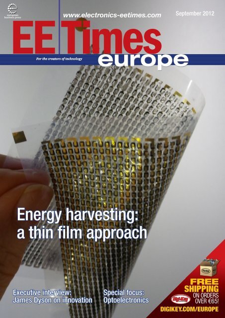
<strong>Energy</strong> <strong>harvesting</strong>:<br />
a <strong>thin</strong> <strong>film</strong> <strong>approach</strong><br />
Executive interview:<br />
James Dyson on innovation<br />
Special focus:<br />
Optoelectronics<br />
FR<strong>EE</strong><br />
SHIPPING<br />
ON ORDERS<br />
OVER €65!<br />
DIGIKEY.COM/ EUROPE
CONTENTS september 2012<br />
opinion<br />
DESIGN & PRODUCTS<br />
4<br />
50<br />
6<br />
8<br />
12<br />
13<br />
14<br />
Uncommon Market: Apple v. Samsung: rights and<br />
wrongs<br />
Last Word: Keeping open source software free<br />
news & TECHNOLOGY<br />
Investigating nano-electromechanical<br />
relay-based<br />
computing<br />
Optogan’s formula for<br />
success: Russian IP, German manufacturing<br />
In the globalized business of LED manufacturing,<br />
large Asian and American<br />
companies define the rules<br />
and set the pace. Unusually<br />
enough in the semiconductor<br />
business, Russian company<br />
Optogan does not only join in<br />
but it keeps growing.<br />
Patents drive innovation<br />
Despite all the legal battles<br />
between Samsung and<br />
Apple, patents are a key way<br />
of protecting investors and<br />
encouraging the exploitation<br />
of innovation, says the<br />
UK’s leading engineer, James<br />
Dyson.<br />
Wireless power outlets designed to support the<br />
IPv6 Internet protocol<br />
Lithium-ion battery pilot production line established<br />
by German research center<br />
Innovative LED geometry could increase light output<br />
by factor of ten<br />
Light-emitting foils could<br />
offer cost-effective OLED<br />
alternative<br />
Researchers from the university<br />
of umea (Sweden)<br />
have produced organic lightemitting<br />
electrochemical cells<br />
(LECs) using a roll-to-roll<br />
compatible process under ambient air conditions.<br />
18<br />
21<br />
23<br />
25<br />
26<br />
28<br />
31<br />
34<br />
36<br />
SPECIAL FOCUS:<br />
- ENERGY HARVESTING<br />
<br />
<strong>Energy</strong> harvesters: a <strong>thin</strong> <strong>film</strong> <strong>approach</strong><br />
During IDTechEx’ last<br />
energy <strong>harvesting</strong> and<br />
Storage <strong>Europe</strong> conference<br />
held in Berlin, <strong>thin</strong><br />
piezoelectric and low footprint<br />
thermoelectric materials<br />
were cited in many<br />
new energy <strong>harvesting</strong> research programs.<br />
Turning waste heat from<br />
industrial piping into<br />
electrical energy<br />
The EverGen PowerStrap<br />
thermoelectric-based<br />
energy <strong>harvesting</strong> solution<br />
produces multiple watts of<br />
power from industrial piping waste heat.<br />
Piezo wireless switch: No battery, no cable, no wear<br />
Self-charging piezo-power cell converts and stores<br />
energy chemically in a single unit<br />
UK leads in energy efficiency rankings as Germany<br />
pushes ahead<br />
- OPTOELECTRONICS<br />
Merging the benefits of CCD<br />
and CMOS for imaging<br />
Over the last decades, the<br />
imager world has seen<br />
numerous publications on<br />
the comparison of CCD and<br />
CMOS imaging technologies.<br />
Enhancing automotive safety through advanced IR<br />
sensor technology<br />
- DATA ACQUISITION<br />
Voice input processing<br />
for automotive speech<br />
recognition systems<br />
Low power system<br />
design optimizations with SAR A/D Converters<br />
15<br />
16<br />
First microwave laser to operate at room<br />
temperature<br />
Custom designed wireless links<br />
The 2012 VLSI Symposia which<br />
took place last summer in<br />
Honolulu came as an opportunity<br />
for researchers to unveil new<br />
short-range wireless link concepts.<br />
46<br />
49<br />
Reader offer<br />
This month, RTX is giving<br />
away 5 RTX4100 Wi-Fi<br />
development kits worth<br />
USD 399 each for <strong>EE</strong><strong>Times</strong><br />
<strong>Europe</strong>’s readers to win.<br />
distribution corner<br />
3 Electronic Engineering <strong>Times</strong> <strong>Europe</strong> September 2012 www.electronics-eetimes.com
UNCOMMON MARKET<br />
Apple v. Samsung: rights and wrongs<br />
By Rick Merritt<br />
BOTH APPLE AND SAMSUNG — are right—and wrong—and<br />
here’s what I <strong>thin</strong>k both sides ought to do to get some sanity<br />
back into the mobile industry and the patent process. There’s<br />
enough greatness and pettiness to go around in the cramped<br />
courtroom of Judge Lucy Koh of San Jose Federal Court where<br />
Apple and Samsung are suing each other for patent infringement.<br />
Apple deserves some kind of acknowledgement for creating<br />
some<strong>thin</strong>g unique with the iPhone, a distinctive looking<br />
handset that put Web access in your pocket along with a phone<br />
and music wrapped in easy to use software. In its own way, the<br />
equally distinctive iPad also was different from tablets that went<br />
before in its clear focus on consumer Web browsing with really<br />
easy-to-use software.<br />
But how do you express that in the arcane language of a<br />
patent? The patent system is encrusted with obtuse procedures<br />
and stiff, vague language. It needs a course with Strunk and<br />
White, the masters of crisp writing and <strong>thin</strong>king. As many have<br />
noted, patents have become a quantity game, not a quality<br />
metric.<br />
Apple did a reasonable job trying to write patents on all the<br />
neat little ideas it put<br />
into its casings and<br />
coded into software.<br />
But they should not<br />
have been written as<br />
a few dozen patents,<br />
rather they should<br />
have been written as<br />
a few dozen claims in<br />
one iPhone patent.<br />
Imagine an iPhone<br />
patent with claims<br />
on the shape of the<br />
device, the metal<br />
bezel, the big screen,<br />
the colorful, well-lit<br />
icons on a black<br />
background that<br />
bounce back and snap to the screen. Imagine them written in<br />
plain English rather than fusty patent-ese.<br />
There would be no problem for a jury of average San Jose<br />
Joes and Janes determining whether or not such a patent was<br />
violated.<br />
Excuse me, now, while I proceed to take Apple off its holierthan-thou<br />
pedestal. I am as touched by anyone by the emotional<br />
language of Steve Jobs that still lives on at Apple and has<br />
been invoked often in Judge Koh’s courtroom, but let’s tell the<br />
other side of that story.<br />
The lofty language of Steve Jobs also acts as a drug to dupe<br />
talented Apple employees into overworking and living unbalanced<br />
lives. It has been used to brainwash Apple employees<br />
into believing they are somehow better than other people that<br />
put their pants on one leg at a time.<br />
Get real, Apple! You don’t own the rectangle with rounded<br />
corners. You didn’t invent the smartphone, capacitive touch<br />
screen displays or browsers on handsets.<br />
You aren’t the only creators of beauty on Planet Earth.<br />
Compared to Samsung you don’t do much work on forwarding<br />
the fundamental technologies that give us the LCDs, batteries,<br />
communications networks and microprocessors we need to<br />
make cool gadgets of all kinds.<br />
That said, you used all those components damn well. So give<br />
yourself a pat on the back, and take that chip off your shoulder<br />
while you are doing it.<br />
And while you’re getting humble, let’s hear a little more<br />
candor about how the electronics industry uses lowcost labor. It<br />
didn’t start with you by any means, but maybe you can use your<br />
clout and fat bankroll to bring some meaningful reforms to labor<br />
practices. After all, your complex designs that require lots of<br />
hand assembly have certainly pushed the edge of this dark side<br />
of the Industrial Revolution 2.0.<br />
Samsung’s side of the street<br />
Samsung’s documents (displayed in court) showing featureby-feature<br />
comparisons of its unreleased S1 handset and the<br />
iPhone are shameful. Each page makes nearly explicit recommendations<br />
for aping features on which Apple has patents.<br />
This is aggressive competition gone way overboard. It is<br />
copying patented<br />
technology. You did<br />
it. You gained the<br />
lead in the smartphone<br />
market in part<br />
because you did it,<br />
and you deserve<br />
to be reined in with<br />
some sort of punishment.<br />
We expected to<br />
see clunky no-name<br />
clones of the iPhone<br />
come out of China<br />
a month after the<br />
iPhone was released,<br />
and we did. We<br />
didn’t expect this<br />
slavish professionalized copying from Samsung.<br />
Still, the lights stay on pretty late in Seoul where they develop<br />
some of the world’s finest chip technology, displays, batteries<br />
and much more. There are hundreds of hard working engineers<br />
in this company and they deserve their due. In becoming one of<br />
its largest customers, Apple has already paid Samsung a form<br />
of silent respect.<br />
When this trial is over, Samsung probably owes Apple a<br />
check, though it may not be for as much as $2.5 billion. Indeed,<br />
Samsung showed some pretty compelling evidence of how the<br />
iPhone appears to infringe some of pretty broad mobile patents<br />
it owns.<br />
Speaking of what’s owed in all this, Apple could write one to<br />
the diligent workers at Foxconn who help it amass its “iFortune”<br />
along with Apple’s retail staff that reportedly works for an average<br />
of about $12 an hour.<br />
After observing the maneuvering in a San Jose court, one<br />
<strong>thin</strong>g seems clear: It’s time to put an end to this patent madness.<br />
4 Electronic Engineering <strong>Times</strong> <strong>Europe</strong> September 2012 www.electronics-eetimes.com
NEWS & TECHNOLOGY<br />
Investigating nano-electro-mechanical<br />
relay-based computing<br />
By Julien Happich<br />
A consortium led by IBM has been awarded €2.44M by the<br />
<strong>Europe</strong>an commission to investigate nano-electro-mechanical<br />
relay based computing for ultra-low power computing applications.<br />
The goal wi<strong>thin</strong> the NEMIAC project (Nano-Electro-<br />
Mechanical Integration And Computation) is to build the world’s<br />
first ever miniaturised electro-mechanical relay based processor.<br />
Nano-electro-mechanical (NEM) relays have practically zero<br />
leakage, an abrupt turn-on transient and a high on-current, and<br />
can also be integrated with CMOS at the<br />
die or wafer level. This makes them promising<br />
candidates for digital logic implementation<br />
in ultra-low power applications,<br />
explains Dinesh Pamunuwa, Lecturer<br />
in Nanotechnology in the Engineering<br />
Department of the Lancaster University<br />
and also in charge of the project’s communication.<br />
“Building a functioning NEM relay<br />
based processor, one would go the full<br />
circle, effectively using electro-mechanical<br />
switches as the basic building block some<br />
200 years after Babbage proposed his<br />
original fully mechanical calculator continues<br />
Pamunuwa.<br />
Several research initiatives have been<br />
pursuing NEM relay based logic, and<br />
many innovative relay architectures have<br />
been proposed that realise logic functionality<br />
in widely different ways, ranging from<br />
combining a basic 3-terminal switching<br />
element in the manner of MOSFETs to<br />
multi-terminal relays and multiple-valued logic implementations.<br />
However the main stumbling block in this technology is<br />
limited switching cycles due to contact material failure. Stiction<br />
caused by surface forces, and material transfer is the main<br />
cause. The relay architecture is also key in ensuring structural<br />
reliability and ensuring scalability. NEM relays that operate on<br />
multiple voltage levels to realise complex logic functionality,<br />
require multiple contacts to be made and have complex timing<br />
sequences are generally not conducive to manufacturability and<br />
repeatability.<br />
The <strong>approach</strong> to be explored wi<strong>thin</strong> NEMIAC - www.nemiac.<br />
eu - is based on an in-plane curved cantilever architecture proposed<br />
by IBM that optimises the electrostatic field distribution<br />
and beam stiffness and allows miniaturisation.<br />
The inclined cantilever design also prevents the beam landing<br />
on the gate due to the different angles of motion of the drain<br />
electrode and the beam. The relay is fabricated using a sacrificial<br />
layer, which ensures precise control of the air gap, with<br />
uniformity throughout the length of the beam.<br />
It also makes possible air gaps smaller than the lithographically<br />
defined limit, which in turn allows precise control of the<br />
electric fields and reduced footprints. In this case, the contact is<br />
realised with platinum silicide and gold.<br />
So far, several functioning microscale switches have been<br />
demonstrated with various footprints, showing “on” resistances<br />
in the order of 5kohm. The target wi<strong>thin</strong> the project is to achieve<br />
a device footprint of 3μm×3μm, a mechanical latency of 50ns<br />
with an operating voltage of 5V, and a reliability of 10 billion<br />
switching cycles.<br />
Using this 3-terminal relay as a primitive, digital logic can<br />
SEM image of a 15.5-μm-long curved cantilever switch.<br />
be realised by adopting a complementary style <strong>approach</strong>, with<br />
pull-up and pull-down networks connecting the output to Vdd<br />
or ground. Both networks are required as the relay can only be<br />
configured to pass a ‘0’ or ‘1’ depending on whether the common<br />
source terminal (beam) is grounded or connected to Vdd,<br />
as NEM relays are ambipolar, and the actuation depends on the<br />
voltage difference between the gate and beam.<br />
A design library of combinational and sequential gates will<br />
be constructed using circuit architectures that are tailored to<br />
the NEM relay characteristics. For example, one way to take<br />
advantage of the ohmic contact and relatively low output impedance<br />
is to have a higher fan-out than would be possible with<br />
minimum-sized CMOS devices. The intended final demonstrator<br />
is a 4-bit microprocessor with a reliability of 1 million switching<br />
cycles.<br />
Researchers from several universities and labs are taking<br />
part in this project, including from the University of Bristol and<br />
the University of Lancaster (UK), from IBM Research in Zurich<br />
and from the Nanoelectronic Device Laboratory (NanoLab) of<br />
École Polytechnique Fédérale de Lausanne (Switzerland), from<br />
ST Microelectronics in Agrate (Italy), and from the KTH Royal<br />
Institute of Technology, Stockholm (Sweden).<br />
6 Electronic Engineering <strong>Times</strong> <strong>Europe</strong> September 2012 www.electronics-eetimes.com
a real BroaDsiDe!<br />
low ohmic precision anD power resisTors<br />
Top performance on small surface areas wiTh low-ohmic precision resisTors<br />
By reversal of the length to width ratio, our Vlx series resistors have larger soldering and contact pads, giving them:<br />
_ better heat dissipation, rthi < 20 K/w<br />
_ higher power rating: 2 w for size 1020, 1 w for size 0612<br />
_ significant increase in mechanical stability<br />
Innovation by Tradition<br />
isabellenhütte heusler Gmbh & co. KG<br />
eibacher weg 3 – 5 · 35683 Dillenburg · phone +49 (0) 2771 934-0 · fax +49 (0) 2771 23030<br />
sales.components@isabellenhuette.de · www.isabellenhuette.de
NEWS & TECHNOLOGY<br />
OPTOELECTRONICS<br />
Optogan’s formula for success: Russian IP,<br />
German manufacturing<br />
By Christoph Hammerschmidt<br />
In the globalized business of LED manufacturing, large<br />
Asian and American companies define the rules and set the<br />
pace. <strong>Europe</strong>an competitors such as Osram and Philips<br />
struggle to keep up. Unusually enough in the semiconductor<br />
business, Russian company Optogan does not only join in but it<br />
keeps growing. With Optogan General Manager Global Sales &<br />
Marketing, Markus Zeiler, <strong>EE</strong> <strong>Times</strong> <strong>Europe</strong> discussed the company’s<br />
recipe for success in this highly competitive market.<br />
<strong>EE</strong><strong>Times</strong> <strong>Europe</strong>: It is rather uncommon that a company with<br />
Russian roots succeeds in Western <strong>Europe</strong>’s high tech markets.<br />
What is the story behind Optogan?<br />
Markus Zeiler: The company has been launched 2004 in Helsinki<br />
by three Russian physicists and entrepreneurs who formerly<br />
worked at the Joffe Institute, one of the world’s leading institutes<br />
in the field of solid state physics. At the Joffe institute<br />
where Nobel laureate Zhores Ivanovich Alferov worked at the<br />
professorship, they conducted breakthrough research on epitaxy<br />
for LED crystals. They also worked for Western companies<br />
and were involved in the development of epitaxy processes<br />
for blue LEDs. From there, they filed for their first patents and<br />
launched their first company.<br />
As early as 2005 they moved to Dortmund, Germany. In the beginning,<br />
the company was funded by a Finnish venture capital.<br />
Later, they also received financial support from Denmark and<br />
the EU. After a couple of years, the first large investors joined in.<br />
One of them was Unixim, a Russian VC fund; another was the<br />
Russian nanotechnology fund Rusnano. Thus, the seat of the<br />
company moved to St. Petersburg from where it staged market<br />
entry in Russia. About one and a half year ago, I accepted the<br />
task of shaping Optogan’s international market appearance.<br />
We are a <strong>Europe</strong>an company with locations in Russia, Finland<br />
and Germany; we run our semiconductor production in<br />
Landshut in Bavaria. This is a clear differentiator against our<br />
competitors in Asia, and our customers reward this <strong>approach</strong>.<br />
Wi<strong>thin</strong> twelve months we received more then 500 inquiries from<br />
distributors across <strong>Europe</strong>, enabling us to select the ones that<br />
best suit us. Recently we launched operations in Italy, Romania<br />
and Turkey. We’re making progress.<br />
<strong>EE</strong><strong>Times</strong> <strong>Europe</strong>: It is certainly not easy to assert oneself against<br />
Asian competitors who produce in very high quantities, driving<br />
price levels down, sometimes with politics coming into play.<br />
M. Zeiler: Sure, it is a challenge. We build our strategy on innovation<br />
and quality. Customers increasingly find out that not<br />
all LEDs are equal and that quality makes a difference. And we<br />
combine quality with slim, cost-effective manufacturing processes.<br />
Being cost-conscious is a precondition if you manufacture<br />
in Germany, but we also offer modular product concepts to<br />
make <strong>thin</strong>gs easy for our customers.<br />
Stages the international expansion for LED manufacturer<br />
Optogan: Markus Zeiler, General Manager Global Sales &<br />
Marketing<br />
<strong>EE</strong><strong>Times</strong> <strong>Europe</strong>: Innovation is not sufficient in itself. Could you<br />
elaborate your <strong>approach</strong>?<br />
M. Zeiler: Our chip technology is based on IP from the professorship<br />
of professor Alferow – nobel award technology, if you<br />
will. With this basis we can well compete in the market, and<br />
we further develop it with subsidies from Skolkovo, in a sense<br />
the Russian pendant of the Silicon Valley. Our unit there, “New<br />
Technologies of Light”, is conducting research and development<br />
for a kind of “People’s LED lamp” – a highly integrated solution<br />
at a low price level.<br />
In this context it is certainly a relevant factor that in Russia the<br />
so called “energy saving lamp”, the CCFL, never was a market<br />
success, its market share never climbed above 4 percent. For<br />
this reason, the Russians migrate from the incandescent bulb<br />
directly to the LED. This is a huge open market, in particular for<br />
highly integrated solutions.<br />
8 Electronic Engineering <strong>Times</strong> <strong>Europe</strong> September 2012 www.electronics-eetimes.com
DESIGNSPARK<br />
UNIQUE<br />
RESOURCES FROM<br />
COMING SOON<br />
A NEW ENGIN<strong>EE</strong>RING<br />
ECO-SYSTEM<br />
www.designspark.com
NEWS & TECHNOLOGY<br />
OPTOELECTRONICS<br />
<strong>EE</strong><strong>Times</strong> <strong>Europe</strong>: Highly integrated<br />
– does this mean that you<br />
integrate the driver circuitry onto<br />
the LED chip?<br />
M. Zeiler: Yes, for instance. This is<br />
one option. Also the connecting<br />
technology is designed to be as<br />
slim as possible. We always have<br />
solutions that are different. In addition,<br />
we have many promising<br />
contacts with large OEMs which<br />
are interested in our technology.<br />
If you look at the details, in the<br />
high-volume retrofit market it even<br />
makes sense to run a production<br />
in <strong>Europe</strong> – if you have a high<br />
degree of automation.<br />
<strong>EE</strong><strong>Times</strong> <strong>Europe</strong>: Where are your<br />
manufacturing locations?<br />
M. Zeiler: Every<strong>thin</strong>g but the chips<br />
are produced in St. Petersburg.<br />
In Dortmund we have R&D and a<br />
pilot production. Our high volume<br />
production is here in Landshut<br />
where we can use existing infrastructure<br />
(from LFoundry), clean rooms etc. We can rent the<br />
infrastructure with an option for further enlargement, ideal for<br />
mass production.<br />
<strong>EE</strong><strong>Times</strong> <strong>Europe</strong>: What’s your estimate of the LED market development<br />
for the future? Do you <strong>thin</strong>k LEDs will quickly displace<br />
CFLs?<br />
M. Zeiler: Yes and no. Quickly in the sense of the traditional<br />
lighting business, yes. This could happen in a time frame of<br />
three to five years while it took some 25 years for the CFL to<br />
gain significant market share in conventional lighting. But one<br />
should not expect a complete changeover. In certain market<br />
segments such as automotive or laptop display backlighting,<br />
LEDs conquered the markets very quickly. In general lighting,<br />
this won’t happen at the same speed. The established lighting<br />
companies do not move that fast. This is a clash of the cultures<br />
– conventional lighting and the fast-moving semiconductor<br />
industry.<br />
<strong>EE</strong><strong>Times</strong> <strong>Europe</strong>: Which market segments do you expect to<br />
grow the fastest? In which applications do LEDs gather acceptance<br />
most rapidly?<br />
Slim, cost effective processes and leading solid-state IP are the two main pillars of Optogan’s<br />
technology strategy.<br />
M. Zeiler: The automotive market is almost saturated with LEDs.<br />
Therefore, we are not active in automotive lighting. We have a<br />
clear focus on general lighting and see the highest potential in<br />
industrial lighting. In this segment, customers can achieve an<br />
ROI in less than three years in some cases. In the consumer<br />
segment we are not so present but we prepare our first concepts.<br />
Here the focus is high lumen per watt and more specifically,<br />
high lumen per dollar.<br />
To address the outdoor lighting market, we have launched a<br />
joint venture with Philips which covers the market for street<br />
lighting in Russia, Belarus and Kazahkstan. In this joint venture,<br />
R&D is in the hands of our partner. For this reason, street lighting<br />
is a “dead spot” on our R&D map.<br />
<strong>EE</strong><strong>Times</strong> <strong>Europe</strong>: Which technology trends in the LED lighting<br />
segments do you find most interesting at the current point of<br />
time?<br />
M. Zeiler: We bet very strongly on modular concepts that embrace<br />
the entire product chain from components to the complete<br />
lamp. In these concepts, complete solutions with tiered<br />
drivers and heat sinks play a major role. In addition, we see a<br />
trend to ever-higher integration. The customers are increasingly<br />
looking for reduced component count through higher integration.<br />
<strong>EE</strong><strong>Times</strong> <strong>Europe</strong>: Is the ability to control dimming a factor in the<br />
market acceptance?<br />
M. Zeiler: Yes – for example in the markets for home lighting<br />
where dimming is a popular feature for retrofit lamps. We also<br />
see an increasing interest for dimming in industrial applications:<br />
it enables users to dim down the lighting in storage halls as long<br />
as nobody works in there and when an employee with a fork<br />
lift enters the place the illumination is turned up. This is also<br />
relevant for dynamic sports areas lighting. End users can save a<br />
lot of money with dimming solutions.<br />
<strong>EE</strong><strong>Times</strong> <strong>Europe</strong>: Are there any standard interfaces and industrial<br />
standards that will gain importance in lighting technology?<br />
M. Zeiler: Of course, for us the Zhaga standard is relevant. We<br />
offer all components and interfaces necessary to position ourselves<br />
in this environment. In industrial markets, it is important<br />
to comply with the DMX / DALI standards. When it comes to<br />
retrofits, however, the Zhaga standard does not help you along;<br />
in this field we need to drive the integration by ourselves and<br />
develop our own ideas.<br />
10 Electronic Engineering <strong>Times</strong> <strong>Europe</strong> September 2012 www.electronics-eetimes.com
NEWS & TECHNOLOGY<br />
EXECUTIVE INTERVIEW<br />
Patents drive innovation<br />
By Nick Flaherty<br />
Despite all the legal battles between Samsung and<br />
Apple, patents are a key way of protecting investors and encouraging<br />
the exploitation of innovation, says the UK’s leading<br />
engineer, James Dyson. More has to be done to generate more<br />
engineers, more patents and more innovation in <strong>Europe</strong> over the<br />
next 20 years.<br />
“I get very depressed and alarmed when I hear people have<br />
copied technology, infringed the patent and got away with it<br />
because I know it will encourage plagiarism and discourage<br />
innovation,” he said. “If you don’t have patents you won’t have<br />
innovation.”<br />
Patents do not stifle<br />
innovation, he says. “I see<br />
patents as a way of increasing<br />
competition not least<br />
because when someone has<br />
discovered a way of doing<br />
some<strong>thin</strong>g and patented it,<br />
if you want to compete with<br />
them you have to develop<br />
your own way of competing<br />
and develop your own<br />
technology, not copy theirs,“<br />
he said. “If someone takes<br />
the risk of spending lots of<br />
time and lots of money in<br />
developing technology and<br />
a lot of money going into<br />
production and making a<br />
success of it, if people are<br />
able to copy it then no one<br />
will conduct innovation, no<br />
one will do research and<br />
development.”<br />
The defence of “prior art” isn’t necessarily helpful, he says,<br />
as a patent is just as much about making the ideas work in<br />
practice, not just protecting the idea.<br />
Dyson, who founded his consumer electronics company in<br />
1992 and now employs 1000 engineers in the UK, sees <strong>Europe</strong><br />
as falling behind countries like China and India in innovation.<br />
“If you look at the number of patents filed in the UK and in<br />
Germany, it’s not that we are filing fewer patents,” he said. “The<br />
problem is that our competitors like China, Korea and India are<br />
filing an increasing number of patents, so the problem is that we<br />
will be left behind.”<br />
While the quality of patents in the US and <strong>Europe</strong> is higher,<br />
this will change with countries like China producing very large<br />
numbers of engineers. “We can’t stay as we are, we have to redouble,<br />
more than re-double, our efforts to develop new technology,<br />
train new engineers and scientists in order to maintain<br />
our position,” he said.<br />
“There are several <strong>thin</strong>gs we need to do. The first is to<br />
increase the number of engineers. We are under-producing the<br />
numbers we need in Britain by 50% and the same is true in<br />
Germany. Iran and Mexico produce twice as many engineering<br />
graduates as Britain so we are under-producing and industry is<br />
short of engineers.<br />
“The second problem is that governments need to recognise<br />
that in order to win world markets you have to produce better<br />
technologies than your competitors because if you can’t you<br />
have no<strong>thin</strong>g to export,” he said.<br />
Part of this comes from providing the right environment for<br />
innovation to thrive, he says, from training engineers to backing<br />
innovation and research. “Developing new technology is very<br />
risky and you have to acknowledge that and incentive people to<br />
develop it,” he said. “You have to have the right sort of structure<br />
to encourage it but you do have to encourage individuals. A lot<br />
of new technology and risk taking happens because an individual<br />
wants to do it and drives the business through, so I <strong>thin</strong>k<br />
you need to encourage that as well.”<br />
One example of this is the James Dyson Awards, which run<br />
every year to find the best young engineers. The 2012 awards<br />
were announced last week (30th August) and includes projects<br />
from 18 countries, from a retrofit LED bulb, that due to its innovative<br />
heatsink, reaches a light output equivalent to 175W and<br />
an eye-controlled camera to earplugs with built-in alarms.<br />
“Innovation is innate,” said Dyson. “We employ a lot of<br />
graduates and you just allow them to develop their technology,<br />
develop their ideas and when you see them, take them and run<br />
with them. We want to change <strong>thin</strong>gs.<br />
It’s not hard to inspire young engineers, he says. “Allowing<br />
them to take risks and making sure it goes into production,<br />
that’s all you have to do as young people have that innovation<br />
and desire to change the world, you just have to use it,” he said.<br />
Dyson is also looking at long term research that will generate<br />
innovation and patents over the next 15 to 20 years.<br />
“We are investing in new materials, <strong>thin</strong>gs that can be substrates<br />
for chips, looking 15 to 20 years into the future because<br />
you have to,” he said. “Electric motors are a very interesting<br />
area of development, as are robotics, batteries and sound, but<br />
electronics is only an enabler. The technology that goes with it<br />
is much harder,” he said.<br />
12 Electronic Engineering <strong>Times</strong> <strong>Europe</strong> September 2012 www.electronics-eetimes.com
POWER DESIGN<br />
Wireless power outlets designed to<br />
support the IPv6 Internet protocol<br />
By Paul Buckley<br />
A new Internet-enabled power outlet was developed by<br />
researchers at the Fraunhofer Institute for Communication<br />
Systems ESK in Munich will allow users to control household<br />
appliances via their smartphone, and reduce their energy costs<br />
into the bargain.<br />
The smart socket was developed in collaboration with the<br />
Fraunhofer Institute for Industrial Mathematics<br />
ITWM in Kaiserslautern and the industrial<br />
partner embedded brains GmbH.<br />
The solution means that soon there will be<br />
no need for special timers to switch lighting<br />
on and off or operate household appliances<br />
when the homeowner is absent. In<br />
future, all this can be done by means of a<br />
smartphone or PC, thanks to Internet-enabled<br />
wireless power outlets that support<br />
the new IPv6 Internet protocol.<br />
“We have been able to connect the<br />
power outlets wirelessly using the IPv6 protocol,” said ESK research<br />
engineer Günter Hildebrandt. “All household appliances<br />
plugged in one of the sockets can be switched on and off remotely<br />
using an IPv6-compatible device such as a smartphone<br />
or laptop PC – from anywhere.”<br />
The wireless power outlets are a component of the HexaBus<br />
home automation system that was developed by the ITWM as<br />
part of the mySmartGrid project - www.mysmartgrid.de.<br />
“The HexaBus components make the smart home of the<br />
future a reality. They enable household appliances to be<br />
controlled intelligently, thus optimizing or reducing electricity<br />
consumption. For example, the householder can start the<br />
washing machine during cheap-rate off-peak hours, or run<br />
the dishwasher when the photovoltaic panels on the roof are<br />
generating sufficient power,” said industrial engineer Mathias<br />
Dalheimer of the ITWM, who leads the SmartGrid project and is<br />
its chief programmer.<br />
In addition to the wireless power outlets,<br />
the HexaBus system employs a specially<br />
designed USB stick that plugs into any<br />
compatible, off-the-shelf router. The user<br />
enters the command to switch on an appliance<br />
via a standard web browser or an<br />
Android-compatible smartphone app. The<br />
router and stick then forward the data to<br />
the power outlet.<br />
The two-way communication function<br />
also allows the wireless power outlet to<br />
send data to the smartphone, informing<br />
the user how much power various appliances are consuming<br />
at any given time. Because the HexaBus system is based on<br />
the IPv6 data communication protocol, a separate IP address is<br />
assigned to each power outlet, and thereby to each connected<br />
appliance, enabling them to be accessed directly. But how did<br />
the researchers go about integrating Internet functionality in the<br />
wireless power outlets and USB sticks? To do so, Hildebrandt<br />
and his team developed special protocol software and an extension<br />
to the Contiki operating system that enables it to handle<br />
the 6LoWpan (IPv6 over Low power Wireless Personal Area<br />
Network) communication protocol.<br />
Lithium-ion battery pilot production line<br />
established by German research center<br />
By Christoph Hammerschmidt<br />
German research center ZSW (Zentrum für Sonnenenergieund<br />
Wasserstoff-Forschung) will install a test production line for<br />
lithium-ion batteries for electric vehicles. The goal of the project<br />
is the development and test of prismatic Li-ion batteries with a<br />
capacity of 20 Ah and more. Such batteries will be used as drive<br />
batteries in electric cars. The pilot production line is scheduled<br />
to start its activities in 2014.<br />
The project has been initialized by industry network KLiB<br />
(Kompetenznetzwerk Lithium-Ionen-Batterien). KLiB counts<br />
numerous companies along the entire battery production value<br />
chain to its members, including BASF, BMW, Bosch, Daimler,<br />
Dow, SB Limotive, Siemens and Varta.<br />
The project aims at industrial-grade production processes<br />
for large Li-ion batteries. At the same time, it offers the chance<br />
to validate new materials and production techniques as well as<br />
methods for quality assurance. “This research production line<br />
will close the gap between manufacturing at the laboratory level<br />
and serial production,” explained KLiB chairman Hubert Jäger.<br />
“This is a central requirement of the German Electromobility<br />
Platform. Wi<strong>thin</strong> the KLiB a number of working groups have<br />
been formed with focus on each stage of the value chain - for<br />
instance materials for anode, cathode, separator and electrolytes,<br />
automation technology, cell production, and battery<br />
production. According to a joint press release of ZSW and KLiB,<br />
the project represents the first opportunity in Germany for all<br />
companies involved to access a value chain-spanning R&D<br />
platform that completes in-house R&D efforts. The project is<br />
funded in part by the federal German research ministry with<br />
23.5 million euros.<br />
www.electronics-eetimes.com Electronic Engineering <strong>Times</strong> <strong>Europe</strong> September 2012 13
NEWS & TECHNOLOGY<br />
LED LIGHTING<br />
Innovative LED geometry could increase<br />
light output by factor of ten<br />
By Christoph Hammerschmidt<br />
New three-dimensional assembly of LEDs could dramatically<br />
multiply the light output compared to today’s planar<br />
devices, <strong>Europe</strong>an scientists hope. The EU research project<br />
GECCO aims at vertically oriented LEDs with much higher efficiency.<br />
Already now, modern high-performance LEDs provide a<br />
bright light output at high efficiency and are meanwhile applied<br />
for automobile headlights, for example. At present, the production<br />
process for these kinds of LEDs is still not cost efficient<br />
enough and also the efficiency of these LEDs needs further<br />
improvement.<br />
The international team of the GECCO project with their partners<br />
from Madrid, Bristol, Lodz, as well as LED manufacturer<br />
Osram is working on achieving their ambitious objectives.<br />
Up to now, LEDs are being constructed in a planar way,<br />
meaning in layers and completely flat. The more light is being<br />
required, the more wafer area has to be produced - an expensive<br />
and laborious <strong>approach</strong>. The idea of the GECCO project is<br />
to assemble LEDs in a three-dimensional way so that actually<br />
every LED consists of a ‘light emitting tower’ from which the entire<br />
vertical surface is emitting light. Obviously the surface of the<br />
tower is much larger compared to the ground area of a planar<br />
LED. And in fact, it is exactly the gain of light emitting area that<br />
leads to a higher<br />
light output.<br />
Thus, the manufacturing<br />
of an LED<br />
becomes much<br />
more cost-effective<br />
and as a result replacing ancient electric bulbs, halogen lamps<br />
as well as energy saving bulbs to LEDs is getting significantly<br />
more profitable. Considering the fact that currently 20% of<br />
electrical energy worldwide is being utilized for illumination, this<br />
innovation provides an enormous potential as far as cost-effectiveness<br />
is concerned. In addition, LED lighting is particularly<br />
important for future electric mobility. <strong>Energy</strong> saving is of utmost<br />
importance in electric cars.<br />
The dimensions of the ‘light emitting towers’ are wi<strong>thin</strong> the<br />
micrometer range. This means approximately one million LEDs<br />
fit on an area of one square millimeter. This process requires<br />
utmost precision which can only be achieved by applying nanotechnology<br />
manufacturing techniques.<br />
The GECCO project is coordinated by Prof. Andreas Waag<br />
from the Institute of Semiconductor Technology of the Braunschweig<br />
Technical University.<br />
Light-emitting foils could offer<br />
cost-effective OLED alternative<br />
By Christoph Hammerschmidt<br />
Researchers from the university of umea (Sweden)<br />
have produced organic light-emitting electrochemical cells<br />
(LECs) using a roll-to-roll compatible process under ambient<br />
conditions. The manufacturing technology developed by the<br />
Swedish team opens the perspective on producing extremely<br />
<strong>thin</strong> light emitting foils in an inexpensive<br />
process.<br />
Applications for the LEC foils could<br />
be informative displays. At a later stage<br />
of development, the foils could also be<br />
used for lighting applications, offering a<br />
cheaper alternative to today’s OLEDs, said<br />
Physics Professor Ludvig Edman from the<br />
Umea university. Edman’s group at Umea<br />
University is focusing on novel organic<br />
compounds (such as light-emitting and<br />
conducting polymers and graphene) and<br />
develops LECs based on such materials. The researchers say<br />
they have dramatically improved the energy efficiency and lifetime<br />
of LECs. They have demonstrated the unique physics and<br />
chemistry behind their operation and recently they enhanced<br />
the performance of LECs to a point where lifetime and efficiency<br />
make LECs useful for signage applications.<br />
The next step in the development was to ensure that the<br />
manufacturing costs can be attractive for commercial applications.<br />
According to a report of the team, published in Nature<br />
Communications, the team managed to deposit a light-emitting<br />
layer and a PEDOT-PSS anode on top of a<br />
flexible cathode-coated substrate mounted on<br />
a roll by means of a slot-die head, using solely<br />
air-stable materials in a roll-coater apparatus.<br />
The layers in the produced LEC device were<br />
found to be highly uneven, and the layer thickness,<br />
for both active layer and anode, was<br />
very thick at approximately 1µm. However,<br />
due to the unique self-doping operation of the<br />
LEC, the light emitted did not suffer from the<br />
rough interfaces, and was in fact found to be<br />
very uniform. This feature is ideal for roll-toroll<br />
processes, as the demands of the coating quality can be<br />
relaxed thus lowering the costs substantially. The researchers<br />
point out that all the steps involved, i.e. preparation of inks,<br />
the subsequent coating of the constituent layers, and the final<br />
device operation all could be carried out under ambient air.<br />
14 Electronic Engineering <strong>Times</strong> <strong>Europe</strong> September 2012 www.electronics-eetimes.com
MATERIAL SCIENCES<br />
First microwave laser to operate<br />
at room temperature<br />
By Nick Flaherty<br />
Scientists in the uk have developed the first solid-state<br />
MASER to operate at room temperature, paving the way for its<br />
widespread adoption.<br />
The researchers from the National<br />
Physical Laboratory (NPL) and Imperial<br />
College London suggest that roomtemperature<br />
MASERs could be used<br />
to make more sensitive medical instruments<br />
for scanning patients, improved<br />
chemical sensors for remotely detecting<br />
explosives; lower-noise read-out<br />
mechanisms for quantum computers<br />
and better radio telescopes for potentially<br />
detecting life on other planets. The<br />
microwave equivalent of a laser, masers<br />
deliver a concentrated beam of microwaves<br />
by amplifying microwaves using<br />
hard inorganic crystals such as ruby. But<br />
they have always required extreme conditions<br />
such as extremely low pressures<br />
or temperatures close to absolute zero<br />
(-273.15°C), as well as strong magnetic<br />
fields from large magnets.<br />
The team have demonstrated pulse<br />
masing in a solid-state device working in<br />
air at room temperature with no applied<br />
magnetic field. This could dramatically<br />
reduce the cost to manufacture and<br />
operate a MASER, which could lead to<br />
them becoming as widely used as laser<br />
technology in a wide range of applications.<br />
“For half a century the MASER has<br />
been the forgotten, inconvenient cousin<br />
of the laser. Our design breakthrough<br />
will enable MASERs to be used by<br />
industry and consumers,” said Dr Mark<br />
Oxborrow, co-author of the study at<br />
NPL. The team used a completely different<br />
type of crystal, namely p-terphenyl<br />
doped with pentacene, to replace ruby<br />
and replicate the same masing process<br />
at room temperature. As a curious twist,<br />
the pentacene dopant turns the otherwise<br />
colourless p-terphenyl crystal an<br />
intense reddish pink.<br />
The first device only works in pulsed<br />
mode for fractions of a second at a time.<br />
They aim to get it to operate continously<br />
over a range of microwave frequencies,<br />
instead of its current narrow bandwidth,<br />
which would make the technology more<br />
useful. In the long-term, the team has a<br />
range of other goals including the identification<br />
of different materials that can<br />
While the world benefi ts<br />
from what’s new, I<strong>EE</strong>E can<br />
focus you on what’s next.<br />
Request a Free Trial<br />
www.ieee.org/tryieeexplore<br />
11-PIM-0544d_Xplore_WhatsNext_5x7.875_FINAL..indd 1<br />
mase at room temperature while consuming less power than<br />
pentacene-doped p-terphenyl.<br />
Develop for tomorrow with<br />
today’s most-cited research.<br />
Over 3 million full-text technical documents<br />
can power your R&D and speed time to market.<br />
• I<strong>EE</strong>E Journals and Conference Proceedings<br />
• I<strong>EE</strong>E Standards<br />
• I<strong>EE</strong>E-Wiley eBooks Library<br />
• I<strong>EE</strong>E eLearning Library<br />
• Plus content from select publishing partners<br />
I<strong>EE</strong>E Xplore ® Digital Library<br />
Discover a smarter research experience.<br />
12/16/11 9:30 AM<br />
www.electronics-eetimes.com Electronic Engineering <strong>Times</strong> <strong>Europe</strong> September 2012 15
NEWS & TECHNOLOGY<br />
VLSI report<br />
Custom designed wireless links:<br />
what the 2012 VLSI Symposia had on offer<br />
By Julien Happich<br />
sponsored by the electron devices Society, the Solid<br />
State Circuits Society and the Japan Society of Applied Physics,<br />
the 2012 VLSI Symposia which took place last summer<br />
in Honolulu came as an opportunity for researchers to unveil<br />
new short-range wireless links and design concepts. Striking<br />
examples include inductive RF coupling solutions for in-chip<br />
communications or through-skull neural sensing data collection.<br />
A team of researchers from the Department of Electrical Engineering<br />
and Computer Sciences at the University of California,<br />
Berkeley, presented a 260GHz fully integrated CMOS transceiver<br />
for wireless chip-to-chip communication. Designed in<br />
65nm CMOS, the OOK modulation (On/Off Key) transceiver was<br />
demonstrated to transmit 10Gb/s over a range of 40mm.<br />
The Tx/Rx dual on-chip antenna array is implemented with<br />
half-width leaky wave antennas. Each transmitter consists of<br />
a quadrupler driven by a class-D-1 PA with a distributed OOK<br />
modulator, and outputs +5 dBm of EIRP. The receiver uses a<br />
double balanced mixer to down-convert<br />
to a Vband IF signal that is amplified with<br />
a wideband IF driver and demodulated<br />
on-chip.<br />
Another team from the same department<br />
presented a 65nm CMOS-integrated<br />
wireless neural sensor with a footprint<br />
of 0.125mm 2 for minimally invasive<br />
surgery, drawing only 10.5μW.<br />
This brain-machine interface consists<br />
of an array of electrodes that extend<br />
vertically to reach relevant neurons, the<br />
wirelessly powered 65nm CMOS IC integrating<br />
four 1.5μW amplifiers (6.5μVrms<br />
input-referred noise for a 10kHz bandwidth)<br />
with power conditioning and<br />
communication circuitry, and an inductive<br />
coupling receiver (RX) coil placed on<br />
top of the active circuitry to minimize the<br />
device’s total footprint.<br />
This neural sensor is claimed to be<br />
able to record action potentials with<br />
enough resolution to<br />
control a complex robotic<br />
prothesis. Data is<br />
then transmitted through<br />
the brain’s dura to a subcutaneous<br />
interrogator.<br />
The four 10-bit, 20kHz<br />
ADCs generate 800kbps<br />
of neural data, which<br />
is backscattered after<br />
each sample is taken.<br />
The interrogator initiates<br />
sampling and communication<br />
by sending a<br />
20kHz beacon.<br />
Fig. 2: Conceptual system diagram of a<br />
wireless neural sensor.<br />
Fig. 1: Sub THz wireless data-link setup.<br />
Fig. 3: ThruChip interface (TCI): (a) inductive coupling, (b) coil by multi-layer wires.<br />
A paper from the Keio University,<br />
Japan, disclosed the use of inductive<br />
coupling, dubbed ThruChip Interface<br />
(TCI) for inter-chip communication. In effect,<br />
the idea is to use near-field wireless<br />
connections between different 3D-chip<br />
levels, instead of silicon vias. Designed<br />
as part of the digital CMOS circuit<br />
integration, this solution is claimed to<br />
be less expensive than using through<br />
silicon vias (TSVs) while offering similar<br />
bandwidth. The researchers listed various<br />
issues with TSVs, including their<br />
excessive footprint or the open failures<br />
they cause due to thermal stress.<br />
They looked at near-field communication<br />
at 50GHz in the 1mm range. The<br />
ThruChip Interface is described as being<br />
surge-tolerant, thermally resilient, while<br />
imposing no restrictions on the circuit<br />
position wi<strong>thin</strong> multi-layer stacks. This<br />
multi-layer interconnection is said to<br />
require only 3% of the footprint of conventional<br />
CMOS I/Os. It<br />
was tested with stacks<br />
of 128 dies, supporting<br />
a data rate per coil of<br />
11Gb/s/ch and aggregating<br />
a data rate of<br />
8Tb/s by arranging 1000<br />
channels wi<strong>thin</strong> 6.4mm 2<br />
while drawing two orders<br />
of magnitude less power<br />
than conventional highspeed<br />
memory links<br />
such as DDR.<br />
This inter-chip, intrastack<br />
communication<br />
16 Electronic Engineering <strong>Times</strong> <strong>Europe</strong> September 2012 www.electronics-eetimes.com
smart system integration 2012<br />
technology could find use not only<br />
in large memory stacks that make<br />
up solid-state drives but also for<br />
multiple processor packages or<br />
for non-contact wafer-level testing<br />
as well as for debugging by probing<br />
internal bus data wirelessly<br />
through a device’s package.<br />
A student in the Department<br />
of Electrical Engineering at the<br />
National Tsing Hua University in<br />
Taiwan, Chang-Ming Lai presented<br />
an ultra-wideband (UWB)<br />
impulse radio timed-array radar<br />
implemented in 0.18μm CMOS<br />
technology.<br />
Using a time-shifted directsampling<br />
architecture, the 4-channel<br />
transmitter array generates<br />
and sends a variety of 10GS/s pulses towards targets while the<br />
receiver array samples the reflected signal in RF domain directly<br />
by time interleaved sampling at 20GS/s. The radar system can<br />
Fig. 4: Human brea<strong>thin</strong>g as seen over a distance of 3m by<br />
the UWB impulse radio timed-array radar.<br />
determine time of arrival (TOA) and<br />
direction of arrival (DOA) through<br />
time-shifted sampling edges which<br />
are generated by on-chip digital-totime<br />
converters (DTC).<br />
According to the student, the<br />
proposed architecture has range<br />
and azimuth resolution of 0.75cm<br />
and 3 degree respectively - see<br />
figure 4.<br />
This UWB impulse radio timedarray<br />
radar system can identify<br />
multiple targets by measuring simultaneously<br />
both direction of arrival<br />
(DOA) and time of arrival (TOA) of<br />
the radio waves scattered by several<br />
objects.<br />
What’s more, for high-fidelity<br />
detection, the scattering waveform of<br />
UWB pulses from the radio interaction<br />
between the radar and the detected objects can be reconstructed<br />
through the analogue signal processing array (ASP) of<br />
the radar receiver.<br />
Game Changer<br />
A Winning Strategy for All your Product Needs!<br />
The LPKF ProtoLaser U3 creates applications for product development that were previously only possible with the help<br />
of large, industrial systems. The machine’s UV laser processes nearly all materials, including laminated substrates.<br />
Visit www.lpkf.com to learn more about the new LPKF ProtoLaser U3.<br />
<strong>Europe</strong>an Microwave Week: 29. – 31.10.2012, Halle 3, Stand B425<br />
electronica: 13. – 16.11.2012, Halle B1, Stand 319<br />
LPKF Laser & Electronics AG Phone +49 (0) 5131-7095-0<br />
www.electronics-eetimes.com Electronic Engineering <strong>Times</strong> <strong>Europe</strong> September 2012 17
DESIGN & PRODUCTS<br />
<strong>Energy</strong> <strong>harvesting</strong><br />
<strong>Energy</strong> harvesters: a <strong>thin</strong> <strong>film</strong> <strong>approach</strong><br />
By Julien Happich<br />
during idtechex’last energy <strong>harvesting</strong> and Storage<br />
<strong>Europe</strong> conference held in Berlin, <strong>thin</strong> piezoelectric and<br />
low foot-print thermoelectric materials were cited in many new<br />
energy <strong>harvesting</strong> research programs and design implementations.<br />
The ultimate goal, as for many electronic applications,<br />
is to replace bulky energy <strong>harvesting</strong> units by lower cost and<br />
conformable <strong>film</strong>-like solutions that are easier to integrate or to<br />
wear.<br />
Michele Guizzetti, Erling Ringgaard and Tomasz Zawada from<br />
Meggitt Sensing Systems presented their use of Lead Zirconate<br />
Titanate (PZT) piezoelectric thick <strong>film</strong>s for energy <strong>harvesting</strong><br />
through the conversion of kinetic energy into electrical energy.<br />
The conversion is done through the vibration of a cantilever<br />
beam covered with piezoelectric material.<br />
The stress induced by the vibrations (kinetic energy) creates<br />
the electrical charges which are harvested as a micro-current.<br />
After studying the optimal design of a piezoelectric bending<br />
structure where the neutral bending axis should be located at<br />
the interface between the PZT materials and the passive (Si)<br />
materials, the team established that for the typical device layer<br />
thickness of the Silicon on Insulator (SoI) wafer being used (20<br />
μm), a layer of 30 to 40 μm of active PZT material should be<br />
used.<br />
Meggitt Sensing System implements this through its proprietary<br />
thick <strong>film</strong> InSensor technology, screen-printing and<br />
integrating piezoelectric layers from 10 to 100 µm in thickness<br />
with a surface resolution of 100x100µm. Dispersed in an organic<br />
vehicle, the piezoelectric material can be screen-printed on a<br />
number of substrates that are compatible with MEMS manufacture<br />
for the design of the bending structures. Using silicon<br />
micromachining and screen-printing techniques, the researchers<br />
developed single clamped cantilever devices measuring<br />
10x10mm 2 , featuring a silicon proof mass at the free end of the<br />
cantilever – see figure 1 and 2.<br />
They tried various cantilever shapes and mass-beam length<br />
ratios (MBR) in both unimorph and bimorph configurations.<br />
Designed in cooperation with the department of micro and<br />
nanotechnology of the technical<br />
university of Denmark (DTU<br />
Nanotech), the devices yielded a<br />
charge sensitivity up to 37nC/g<br />
at 0.5 g peak, delivering up to<br />
4V at 0.5 g peak for the bimorph<br />
device, generating 15 to 20μW of<br />
power at moderate accelerations<br />
of about 0.5 g.<br />
The team demonstrated that<br />
the bandwidth of these microgenerators<br />
can be increased by<br />
introduction of non-linear effects<br />
such as magnetic coupling or<br />
mechanical non-linearity. These<br />
PZT thick-<strong>film</strong> micro-generators<br />
can be used to power sensor<br />
nodes for energy-autonomous,<br />
wireless measurement of acceleration<br />
and temperature.<br />
Fig. 1: Meggitt’s clamped cantilever device showing a silicon<br />
proof mass at the free end of the cantilever.<br />
Fig. 3: Algra’s Dynasim foils with a screen printable<br />
piezoelectric lacquer can be used in flexural mode.<br />
Fig. 2: A wafer showing<br />
several piezoelectric bending<br />
structures.<br />
Dr. Venkatesh Sivasubramaniam<br />
from swiss-based<br />
company Algra showcased a<br />
wireless piezoelectric switch<br />
for handheld or wall-mounted<br />
applications. Commercialized<br />
as Dynapic Wireless, the low<br />
actuation force (5N) switch<br />
relies on a simple piezoelectric<br />
membrane sandwiched between<br />
an overlaid electrode,<br />
a spacer defining the actuation<br />
displacement and a <strong>thin</strong> PCB on which the electronics is<br />
assembled.<br />
The circuitry includes a custom power management ASIC,<br />
a low power MCU and an RF transceiver capable of running<br />
standard low-power wireless protocols. The switches have been<br />
tested to over 10 million cycles, a longevity that is due to the<br />
low homogeneous stress level applied to the circular piezoelectric<br />
membrane, claims the company. As well as its noise-free<br />
switch, Algra discussed flexible<br />
piezoelectric polymer composite<br />
sensor foils – see figure 3. Instead<br />
of a sintered piezoelectric disc,<br />
Algra’s Dynasim foils feature a<br />
screen printable piezoelectric<br />
lacquer built up on electrode material<br />
using a roll-to-roll thick <strong>film</strong><br />
deposition technique. To be used<br />
in flexural mode, the foil could<br />
deliver enough energy to wake<br />
up a microprocessor from a deep<br />
sleep mode.<br />
A supplier of PMN-PT (lead<br />
magnesium niobium-lead titanate)<br />
single piezoelectric crystals,<br />
iBULe Photonics’ CEO Sang-Goo<br />
Lee presented his company’s<br />
<strong>approach</strong> to acoustic micro-gener-<br />
18 Electronic Engineering <strong>Times</strong> <strong>Europe</strong> September 2012 www.electronics-eetimes.com
TFTs<br />
Rugged TFT-LCD Modules<br />
viewing excellence<br />
semis.info@meg.mee.com · www.mitsubishichips.eu Stand 1-639
DESIGN & PRODUCTS<br />
<strong>Energy</strong> <strong>harvesting</strong><br />
ators. The company has the know-how to bond PMN-PT single<br />
crystals onto silicon wafers and then micro-machine them into<br />
resonating structures of appropriate thicknesses (down to 15<br />
microns), in effect, designing what it calls piezoelectric micromachined<br />
ultrasonic transducers (P-MUT).<br />
The efficiency of PMN-PT vibrational energy harvesters is<br />
about seven times that of PZT-based devices, highlighted Lee.<br />
iBULe Photonics has built<br />
up prototypes of monolayer<br />
acoustic generators arrays<br />
measuring 30x30mm,<br />
featuring arrangements of<br />
10x10 microgenerator cells<br />
each 2.5mm in diameter<br />
and only 0.01mm <strong>thin</strong> – see<br />
figure 4.<br />
With 15mWh delivered<br />
by each cell at a sound<br />
pressure of 1Pa at 12.5kHz,<br />
the whole array could yield<br />
up to 1500mWh of usable<br />
power. The company is also<br />
Fig. 4: One of iBULe Photonics’<br />
microgenerator cells, 2.5mm in<br />
diameter and only 0.01mm <strong>thin</strong>.<br />
looking at superposing several such arrays to increase power<br />
output. Future developments include the use of PMN-PT/epoxy<br />
piezocomposite materials to build up 3-dimensional energy <strong>harvesting</strong><br />
structures and the use of <strong>thin</strong>-<strong>film</strong> batteries for energy<br />
storage on the same device.<br />
Fig. 5: AIST’s thermoelectric conversion <strong>film</strong> devices fabricated<br />
by stencil printing yields a fully flexible prototype.<br />
A researcher at the National Institute of Advanced Industrial<br />
Science and Technology (AIST) from Japan, Kouji Suemori presented<br />
new materials printable into thermoelectric conversion<br />
devices. Unlike many competing thermoelectric materials, the<br />
carbon nanotube-polymer composite developed by the AIST<br />
does not contain rare metals such as Bi and Te.<br />
The composite is mixed mechanically at a nanometer-level<br />
with a resin matrix in an inking solvent and can then be printed<br />
onto flexible substrates such as plastic <strong>film</strong>s and papers. Adding<br />
drying and sintering steps, this process enables the manufacture<br />
of thermoelectric conversion devices onto 20µm-thick<br />
substrates that conform to any shape for optimum conversion<br />
efficiency.<br />
The thermoelectric energy harvester is obtained through<br />
stencil printing, patterning tiny material sections between top<br />
and bottom electrodes to form many thermoelectric cells that<br />
are connected in series – see figure 5.<br />
As shown in figure 5, the researchers prototyped a flexible<br />
thermoelectric conversion <strong>film</strong> featuring 1000 such devices in<br />
series, each cell measuring 0.5×0.8×0.3mm.<br />
This thermoelectric conversion<br />
<strong>film</strong> remained operational even<br />
when bent at 5mm of curvature.<br />
It has shown to be conformable<br />
to both curved and spherical surfaces<br />
while being able to generate<br />
power with small temperature<br />
differences.<br />
This could even be used in<br />
garments for wearable power<br />
generation. As a lab experiment,<br />
the temperature difference created<br />
by one’s hand placed on<br />
top of the <strong>film</strong> fixed to a 10°C<br />
plate generated 108.9mV - see<br />
figure 6.<br />
Fig. 7: Wibicom’s photovoltaic antennas for UWB<br />
transceivers. (a) Dipole antenna. (b) Loop antenna.<br />
Fig. 6: A flexible thermoelectric conversion <strong>film</strong> generating<br />
power through the temperature difference created by a hand<br />
on the <strong>film</strong> installed on a 10 °C plate generated 108.9mV.<br />
Taking a look at every<strong>thin</strong>g <strong>thin</strong>, Wibicom should be cited<br />
for its innovative <strong>approach</strong> to antenna design, directly powered<br />
by dye sensitised cells fabricated on top of an antenna foil.<br />
The small technical consulting company from the Netherlands<br />
presented its WibiSol concept antenna capable of <strong>harvesting</strong><br />
energy from ambient light or the sun and simultaneously transmitting<br />
and receiving RF signals – see figure 7.<br />
In previous papers, the company founder & CEO Mina<br />
Danesh detailed the implementation of dipole and loop antennas<br />
designed for 3.1 to 10.6GHz ultrawideband communications,<br />
covered with amorphous-silicon PV cells based on<br />
hydrogenated amorphous silicon (aSi:H). The dipole antenna<br />
uses two separate PV cells measuring 20×20mm 2 , each having<br />
its own DC connections,<br />
connected in parallel.<br />
The loop antenna has<br />
five-series DC-connected<br />
cells. In this case the PV<br />
module is 25mm wide<br />
and 110mm long with a<br />
loop diameter of 36mm.<br />
Here again for the continuous<br />
operation of sensor<br />
nodes, the photovoltaic<br />
energy would have to be<br />
stored in supercapacitors<br />
or in <strong>thin</strong>-<strong>film</strong> rechargeable<br />
batteries.<br />
20 Electronic Engineering <strong>Times</strong> <strong>Europe</strong> September 2012 www.electronics-eetimes.com
Turning waste heat from industrial piping<br />
into electrical energy<br />
By Josh Moczygemba<br />
Marlow Industries’ EverGen PowerStrap is a thermoelectric-based<br />
energy <strong>harvesting</strong> solution that produces multiple<br />
watts of power by conversion of waste heat from industrial piping<br />
directly into electrical energy. This product provides remote<br />
power for wireless sensors, wireless transmitters, actuators,<br />
and controls in large industrial, chemical, oil and gas infrastructures.<br />
This energy <strong>harvesting</strong> solution can be customized to fit<br />
any pipe diameter and pipe orientation, without modification to<br />
existing pipeline infrastructure.<br />
Power output is proportional to the temperature difference<br />
from the pipe surface to ambient, and the number of straps<br />
employed in the application. The EverGen PowerStrap is<br />
composed of three main components: Bi2Te3 thermoelectric<br />
generators (TEGs), anodized aluminium clamping straps and<br />
natural convection heat sinks.<br />
The TEG modules produce power from the temperature<br />
difference between the pipe wall and ambient air. They have a<br />
maximum operating temperature of 230°C and are sealed for<br />
environmental protection. The clamping straps provide a geometrical<br />
transition from the round exterior pipe wall to the flat<br />
TEG surface. The clamp attaches with a compression technique<br />
that requires no modifications to the pipe wall. Straps are<br />
custom sized based on pipe diameter. The heat sinks dissipate<br />
heat to the ambient environment, they are typically made of<br />
aluminium with anodized coatings.<br />
Design methodology<br />
Maximizing power in the EverGen P owerStrap system requires<br />
a balance between the thermal and electrical system design.<br />
Thermal optimization starts by defining a thermal load resistance<br />
ratio (m).<br />
CircularConnectorsAd-<strong>EE</strong><strong>Times</strong>_Layout 1 8/22/12 2:25 PM Page 1<br />
Josh Moczygemba is Power Generation Product Engineering<br />
Manager at Marlow Industries - www.marlow.com<br />
Circular Connectors<br />
Our vertical integration gives you custom<br />
MIL & Hi-Rel connectors FAST!<br />
• Custom EMI filtered and unfiltered connectors<br />
• We make our own planar and tubular capacitors,<br />
shells, shields, seals and grommets<br />
• Vertical integration means higher quality and the<br />
industry's shortest lead times (8-10 weeks, std)<br />
• Filtered connector styles include MIL-DTL-38999,<br />
MIL-DTL-83723, MIL-DTL-26482, MIL-DTL-55116<br />
and MIL-DTL-24308<br />
• Our EMI expertise gives you a better filtered connector<br />
• 100% testing for critical electrical parameters<br />
• Harnessing products to IPC-A-610 and J-STD-001<br />
Check out our new<br />
Specialty Connector Video @<br />
SpecEMC.com/specvid<br />
Call +49-9122-7950 or visit apitech.com/eis<br />
www.electronics-eetimes.com Electronic Engineering <strong>Times</strong> <strong>Europe</strong> September 2012 21
DESIGN & PRODUCTS<br />
ENERGY HARVESTING<br />
Where R TEG<br />
,thermal is the thermal<br />
resistance of the thermoelectric elements,<br />
HSR is the thermal resistance from the hot<br />
source to the hot side of the thermoelectric<br />
elements and CSR is the thermal resistance<br />
from the cold source to the cold side of the<br />
thermoelectric elements.<br />
Figure 2 represents the impact on<br />
performance that different thermal load<br />
ratios have on the power output. For most<br />
thermoelectric applications, designing<br />
for a thermal load resistance ratio of one<br />
ensures the best performance possible. In<br />
the case of the EverGen PowerStrap, the<br />
best performing natural convection heat<br />
sink was chosen, based on orientation, size, cost<br />
and manufacturing constraints. Computational fluid<br />
dynamics (CFD) software was used to aid in the heat<br />
sink design optimization. Next, the TEG devices were<br />
designed using Marlow’s proprietary TEG software to<br />
match the thermal resistivity of the natural convection<br />
Fig. 1: A 10-inch diameter<br />
implementation of the EverGen<br />
PowerStrap energy harvester from<br />
Marlow.<br />
generator module was held in compression between<br />
the heat sink and the strap base with two<br />
stainless steel bolts fitted with insulating phenolic<br />
washers. Thermal pads on both sides of the TEG<br />
were used to improve thermal resistance at the<br />
hot (strap) and cold (heat sink) interfaces. The<br />
clamping strap base was divided into three identical<br />
sections that form a compression fit around<br />
the pipe when bolted together. A series of lab<br />
tests were conducted with this design that mimicked<br />
varying operating conditions throughout the<br />
year. The test assembly was made from a section<br />
of 10” diameter steel pipe that was capped at<br />
one end and filled with oil. Submersible heaters,<br />
heat sinks under pure natural convection conditions.<br />
The electrical system optimization is analogous to<br />
the thermal system. For maximum power transfer, the<br />
internal electrical resistance of the power source must match<br />
the electrical resistance of the load being powered. In this case,<br />
the electrical load ratio (n) is defined as<br />
Where R load<br />
is the electrical resistance of the load being powered<br />
and R TEG<br />
,electrical is the electrical resistance of the TEG<br />
module under operating conditions.<br />
Figure 3 highlights why this is a particularly important consideration<br />
when designing thermoelectric power generation<br />
systems. In reality, both electrical and thermal characteristics of<br />
the TEG are interrelated with the thermal resistance of the TEG<br />
being affected by the electrical load connected to the TEG. In<br />
real world applications, where operating conditions and loads<br />
vary, it would be very difficult to always ensure proper load<br />
matching across all operating points due<br />
to temperature dependant properties<br />
of the TEG. Fortunately, commercially<br />
available maximum power point tracking<br />
(MPPT) controllers originally designed for<br />
the solar industry can also perform this<br />
function for thermoelectric systems. In<br />
cases where hybrid solar/thermoelectric<br />
systems are employed, a single MPPT<br />
controller accommodates both. The only<br />
design requirements are that the TEG<br />
system voltage and current outputs for<br />
the operating range meet the input requirements<br />
of the MPPT controller.<br />
Test setup<br />
Figure 1 shows a photograph of a 10-<br />
inch diameter EverGen PowerStrap. The<br />
unit was designed for outdoor use, 120°C<br />
operation in a vertical orientation for an<br />
industrial exhaust pipe. Twelve identical<br />
TEG and heat sink assembly sections<br />
were spaced evenly around the perimeter<br />
of the strap base. Each thermoelectric<br />
Fig. 2: Impact of thermal load<br />
matching on the EverGen PowerStrap<br />
design.<br />
Fig. 4: Expanded view sketch of<br />
the thermocouple placement on<br />
the test assembly.<br />
Fig. 5: The EverGen PowerStrap<br />
test results.<br />
Fig. 3: Impact of electrical<br />
load matching on the EverGen<br />
PowerStrap.<br />
attached to an electronic temperature controller, were used to<br />
control test assembly wall temperature. The PowerStrap was<br />
clamped to the exterior of the test assembly, with non-setting<br />
thermal mastic applied between the pipe wall and the strap<br />
base to aid in heat transfer. During testing, ambient temperature<br />
around the test assembly was altered to reflect seasonal changes.<br />
Both natural convection and forced convection up to 6.5<br />
mph were studied. Omega OM-420 data acquisition equipment<br />
was used to collect temperature, voltage and current measurements<br />
during testing. Figure 4 is an expanded view sketch that<br />
depicts thermocouple placement on the test assembly. Readings<br />
were collected and recorded in two second intervals.<br />
Test results<br />
The results of this testing, compared against model<br />
predictions, are shown in Figure 5 for two different<br />
pipe temperatures covering a wide range in ambient<br />
conditions. From the data, it is obvious that the<br />
EverGen PowerStrap performance is maximized<br />
when ambient temperatures are the coldest. This<br />
is to be expected since thermoelectric efficiency is<br />
greater for larger temperature differentials. In real<br />
world operation, this means that the PowerStrap<br />
performance will be maximized during the colder<br />
months of the year. Such performance makes this<br />
product a natural complement to solar cells, which<br />
usually perform poorly during the winter months.<br />
Another key point is that there is significant performance<br />
increase, by as much as 40%, when typical<br />
outdoor wind conditions are accounted for. For<br />
applications requiring higher power levels, multiple<br />
units can be employed. The data also shows that the<br />
model predictions close well with experimental data.<br />
By expanding the model to include different pipe<br />
temperatures and diameters, performance under different<br />
operating scenarios can be predicted.<br />
22 Electronic Engineering <strong>Times</strong> <strong>Europe</strong> September 2012 www.electronics-eetimes.com
Piezo wireless switch: No battery,<br />
no cable, no wear<br />
By Dr. Venkatesh Sivasubramaniam<br />
The principles behind using piezoelectric materials for<br />
energy <strong>harvesting</strong> are well known since the early 70’s. Despite<br />
various patents on such energy <strong>harvesting</strong> implementations,<br />
barely few inventions have been crystallized into industrial<br />
products. The primary limitation of deploying a piezoelectric<br />
material is related to its poor mechanical reliability while it is<br />
often bowed and clamped in a certain manner so as to generate<br />
the required voltage by mechanical deformation. In reality<br />
the deflection of most piezoelectric cantilevers easily exceeds<br />
a millimetre. Additionally the piezoelectric cantilever suffers<br />
inhomogeneous stress concentrations due to clamped boundary<br />
conditions. A larger deflection with inhomogeneous stress<br />
states has a negative influence on the mechanical integrity of<br />
the piezoelectric energy <strong>harvesting</strong> source.<br />
As early as the 1990’s, the Swiss-based company Algra<br />
demonstrated that the reliability issues of bending piezoelectric<br />
Dr. Venkatesh Sivasubramaniam is Material Scientist<br />
at Algra AG – www.algra.ch<br />
Fig. 1: Expanded view of the Dynapic<br />
technology showing the multilayer<br />
laminate construction with the<br />
piezoelectric disc.<br />
materials can be<br />
circumvented with<br />
two proprietary<br />
technologies known<br />
as Dynapic and Dynasim.<br />
The Dynapic<br />
technology offers an<br />
innovative solution<br />
where a discshaped<br />
piezoelectric<br />
material is bent wi<strong>thin</strong> a controlled range from 100 to 300<br />
µm through the use of a multilayered sandwich construction -<br />
see figure 1. Figure 2 shows side by side the stress analysis of a<br />
typical cantilever bending and the Dynapic piezo key. A homogenous<br />
stress distribution ensures the mechanical integrity of the<br />
Dynapic piezo keys, enabling such implementations to exceed<br />
10 million switching cycles. Algra’s latest innovation, Dynapic<br />
Wireless - as shown in figure 3, demonstrates that energy<br />
from the Dynapic piezo switch alone is sufficient to be used
DESIGN & PRODUCTS<br />
ENERGY HARVESTING<br />
Fig. 2: A) Inhomogenous stress<br />
distribution for a clamped piezoelectric<br />
cantilever. B) Stress optimized layer for<br />
a simple Dynapic concept.<br />
in self-powered<br />
wireless switching<br />
applications. The<br />
energy generated by<br />
a single key stroke<br />
is sufficient to wake<br />
up a microcontroller<br />
and transmit<br />
a coded signal to<br />
a remote receiver.<br />
The wireless signal itself could be deployed for simple ON/OFF<br />
operation. These switches could be deployed in household devices<br />
such as lights or window blinds but would also be suitable<br />
for industrial automation.<br />
Because there is almost no mechanical movement, the<br />
Dynapic Wireless switch comes as a compact and robust module<br />
easy to integrate into existing or new designer switches. The<br />
switch is noise-free and has a low force of activation of approximately<br />
5N.<br />
Dedicated power management<br />
for piezo switches<br />
The primary challenge involved in such a piezoelectric switch<br />
was to develop suitable power management devices. There are<br />
several energy management ICs and voltage converters on the<br />
market but most are aimed at battery-based applications, where<br />
Fig. 3: Block diagram of the Dynapic Wireless switch.<br />
the voltage from a battery is reduced or boosted. What’s more,<br />
most of these power management devices are developed for<br />
energy harvesters that work on continuous vibrational modes.<br />
Linear Technology has recently introduced the “LTC3588-1”,<br />
which is an AC/DC converter for piezo vibrational harvesters.<br />
These do perform very well for piezo harvesters based on<br />
continuous vibrational modes, optimized for a resonant frequency.<br />
However such components could not be deployed for<br />
the Dynapic piezo keys, as the energy comes in voltage busts<br />
generated by intermittent finger pressure. The piezo keys deliver<br />
high voltages (typically 20-50 V) at very low current with a typical<br />
time span of approximately 100ms. Thus, designers must<br />
wake up the microcontroller wi<strong>thin</strong> a short period of time and<br />
transmit a simple<br />
coded signal<br />
to the receiver<br />
using the energy<br />
generated in the<br />
order of 2-20 µJ –<br />
see figure 5. This<br />
requires custom<br />
Fig. 4: The compact form factor of<br />
Dynapic Wireless allows various design<br />
developed power<br />
management<br />
electronics that<br />
can function at<br />
possibilities.<br />
extremely low currents/high impedances.<br />
For this purpose, Algra has developed a power management<br />
ASIC that includes an active bridge rectifier with a voltage<br />
conditioner drawing less than 50nA typically with a forward<br />
bias voltage under 40mV. It is worth mentioning that the wireless<br />
protocol used here is proprietary, designed to work with<br />
ultra-low power radio<br />
modules. We currently<br />
achieve a wireless<br />
transmission distance<br />
of 10 to 30m at a frequency<br />
of 2.4 GHz.<br />
Algra is experimenting<br />
further with high<br />
performance ceramics<br />
for the piezoelectric membrane, which could lead together<br />
with custom designed ASICs to more flexible solutions based<br />
on standard wireless protocols. More harvested energy should<br />
allow the switch to send redundant signals for increased reliability.<br />
The Dynapic piezo can also be used as an energy source for<br />
small embedded systems where wireless communication is not<br />
required. This could be the case for contact (shock) loggers,<br />
say in the transportation industry. Besides the Dynapic Wireless,<br />
Algra also manufactures<br />
flexible piezoelectric polymer<br />
composite sensor foils commercially<br />
known as Dynasim<br />
– see figure 6. The layered<br />
construction is very similar to<br />
the Dynapic, but instead of a<br />
sintered piezoelectric disc, a<br />
screen printable piezoelectric<br />
lacquer with suitable electrode<br />
material is built-up using a<br />
roll-to-roll thick <strong>film</strong> deposition<br />
technique. This screen<br />
printing technique supports<br />
the fast serial production of<br />
sensor foils in various forms<br />
and shapes.<br />
Dynasim foils are already proven for their reliability and<br />
efficient production in large quantities for keyboard-based applications.<br />
Currently Algra is exploring new applications where<br />
the generated energy would wake up microcontrollers from a<br />
deep sleep state - see figure 7. In Sleep mode, a microcontroller<br />
is placed in its lowest current consumption state whereby the<br />
device’s oscillator is turned off, so there are no system clocks<br />
running. However, the I/O ports maintain the status they had before<br />
the SL<strong>EE</strong>P instruction was executed. In order to minimize<br />
the Sleep mode’s power consumption, the output ports should<br />
not be sourcing or sinking any current before going into Sleep<br />
mode, optimising battery life. All the unused I/O pins should be<br />
configured as inputs and pulled either high (VDD) or low (VSS).<br />
Figure 7 shows a graph where the energy (yellow trace) from<br />
pressing a Dynasim key generates the energy required to wake<br />
up/ provide interrupts to the micro controller (green trace) and<br />
set it to a toggle state. In contrast to capacitive keys, the piezo<br />
key does not consume<br />
any power from the<br />
supply at all, allowing<br />
for a Sleep mode current<br />
that only consists<br />
of the microcontroller’s<br />
leakage. For this reason<br />
such Dynasim piezo<br />
foil applications could<br />
open new areas of<br />
optimization in power<br />
management.<br />
Fig. 5: Voltage monitoring over the<br />
storage capacitor.<br />
Fig. 6: The Dynasim screenprinted<br />
piezoelectric<br />
polymer composite foils are<br />
manufactured using fast and<br />
efficient roll-to-roll screen<br />
printing technique.<br />
Fig. 7: The Dynasim key used to<br />
wake up a microcontroller.<br />
24 Electronic Engineering <strong>Times</strong> <strong>Europe</strong> September 2012 www.electronics-eetimes.com
Self-charging piezo-power cell converts and<br />
stores energy chemically in a single unit<br />
Researchers from the Georgia Institute of Technology have<br />
developed a self-charging power cell that directly converts mechanical<br />
energy to chemical energy, storing the power until it is<br />
released as electrical current. By eliminating the need to convert<br />
mechanical energy to electrical energy for charging a battery, the<br />
new hybrid generator-storage cell uses mechanical energy more<br />
efficiently than systems using separate generators and batteries.<br />
he power cell consists of a cathode made from lithium-cobalt<br />
oxide (LiCoO 2<br />
) and an anode consisting of titanium dioxide (TiO 2<br />
)<br />
nanotubes grown atop a titanium <strong>film</strong>.<br />
frequency of 2.3 Hertz, the researchers increased the voltage<br />
in the power cell from 327 to 395 millivolts in just four minutes.<br />
The device was then discharged back to its original voltage with<br />
a current of one milliamp for about two minutes. The researchers<br />
estimated the stored electric capacity of the power cell to<br />
be approximately 0.036 milliamp-hours. So far, Wang and his<br />
research team – which included Xinyu Xue, Sihong Wang, Wenxi<br />
Guo and Yan Zhang – have built and tested more than 500 of the<br />
power cells. Wang estimates that the generator-storage cell will<br />
be as much as five times more efficient at converting mechanical<br />
energy to chemical energy for as a two-cell generator-storage<br />
system.<br />
We have always known<br />
what we wanted to do...<br />
The two electrodes are separated by a<br />
membrane made from poly(vinylidene<br />
fluoride) (PVDF) <strong>film</strong>, which generates a<br />
piezoelectric charge when placed under<br />
strain. When the power cell is mechanically<br />
compressed, the PVDF <strong>film</strong> generates<br />
a piezoelectric potential that serves<br />
as a charge pump to drive the lithium<br />
ions from the cathode side to the anode<br />
side. The energy is then stored in the<br />
anode as lithium-titanium oxide. By<br />
harnessing a compressive force, such<br />
as a shoe heel hitting the pavement from<br />
a person walking, the power cell generates<br />
enough current to power a small<br />
calculator. Charging occurs in cycles<br />
with the compression of the power cell<br />
creating a piezopotential that drives the<br />
migration of lithium ions until a point at<br />
which the chemical equilibrium of the two<br />
electrodes are re-established and the distribution<br />
of lithium ions can balance the<br />
piezoelectric fields in the PVDF <strong>film</strong>.<br />
When the force applied to the power cell<br />
is released, the piezoelectric field in the<br />
PVDF disappears, and the lithium ions<br />
are kept at the anode through a chemical<br />
process. The charging cycle is completed<br />
through an electrochemical process<br />
that oxidizes a small amount of lithiumcobalt<br />
oxide at the cathode to Li1-xCoO 2<br />
and reduces a small amount of titanium<br />
dioxide to LixTiO 2<br />
at the anode. Compressing<br />
the power cell again repeats the<br />
cycle. When an electrical load is connected<br />
between the anode and cathode,<br />
electrons flow to the load, and the lithium<br />
ions wi<strong>thin</strong> the cell flow back from the<br />
anode side to the cathode side. Using<br />
a mechanical compressive force with a<br />
Mission-critical, high reliability resistive products.<br />
they’re our specialty. For over forty years we<br />
have applied painstaking research, rigid quality<br />
programs,<br />
and hard work<br />
to produce the<br />
world’s most<br />
reliable resistors!<br />
Let us worry<br />
about quality,<br />
reliability<br />
and delivery.<br />
That is what we do.<br />
State of the Art, Inc.<br />
Resistive PRoducts<br />
Made<br />
in the USA.<br />
www.electronics-eetimes.com Electronic Engineering <strong>Times</strong> <strong>Europe</strong> September 2012 25
DESIGN & PRODUCTS<br />
ENERGY HARVESTING<br />
UK leads in energy efficiency rankings<br />
as Germany pushes ahead<br />
By Nick Flaherty<br />
Somewhat surprisingly, the UK is leading the energy efficiency<br />
ranking of the world’s twelve largest economies, according to<br />
the International <strong>Energy</strong> Efficiency Scorecard by the American<br />
Council for an <strong>Energy</strong>-Efficient Economy (AC<strong>EE</strong>E). Despite this<br />
finding, the study also reveals that there are still vast untapped<br />
efficiency opportunities.<br />
The rankings extend AC<strong>EE</strong>E’s established energy efficiency<br />
ranking of US states to 12 of the world’s largest economies,<br />
representing 78 percent of global gross domestic product; 63<br />
percent of global energy consumption; and 62 percent of the<br />
global carbon-dioxide equivalent emissions.<br />
The countries were ranked out of 100 possible points in 27<br />
categories, across four groups, from national energy use to<br />
buildings, industry, and transportation. Germany scored top in<br />
national efforts, China for buildings, the UK for industry and a<br />
tie among Italy, China, Germany, and the UK on transportation –<br />
see figure 1.<br />
“The UK and the leading economies of <strong>Europe</strong> are now well<br />
ahead of the United States when it comes to energy efficiency,”<br />
said AC<strong>EE</strong>E Executive Director Steven Nadel. “This is significant<br />
because countries that use energy more efficiently require fewer<br />
resources to achieve the same goals, thus reducing costs,<br />
preserving valuable natural resources, and creating jobs. Unfortunately,<br />
our results show that nowhere is the vast potential for<br />
improvements in energy efficiency being completely realized.<br />
While many countries achieved notable success, none received<br />
a perfect score in any category – proving that there is much that<br />
all countries can still learn from each other. For example, the<br />
United States scored relatively high in buildings, but was at the<br />
bottom of the list in transportation.”<br />
The Eco-Routemaster hybrid buses that rolled out in London<br />
for the Olympics come as an example of energy <strong>harvesting</strong><br />
moving into transportation. These are using energy <strong>harvesting</strong><br />
to simplify and enhance the communication systems. Pressing<br />
the bell push for the ‘stop’ button in the bus generates enough<br />
electrical power for a wireless module to activate the stop display<br />
and an audible stop signal.<br />
While other push-buttons need to be connected to the signal<br />
receiver at the bus driver’s position via metres of cable, the stop<br />
button manufactured by UK company BMAC uses an energy<br />
converter which offers more than 300,000 switching cycles<br />
and a small batteryless wireless module – see figure 2. The<br />
radio signal is unique to each stop button, ensuring no interference<br />
with other buttons in this bus or other buses nearby. The<br />
receiver module is connected to the bus’ electrical system and<br />
the bell pushes are then fitted into place. After installation, each<br />
stop button in a bus is programmed for its own logic circuit – for<br />
example, front, middle, rear or wheelchair users. The energy<br />
<strong>harvesting</strong> wireless solution saves up to 100 metres of cabling<br />
in the bus, saving installation effort and avoiding the need to<br />
replace defective cables, which can be time-consuming.<br />
“The concept of a wireless bell push system has been an aspiration<br />
for bus manufacturers for years. It takes many hours on<br />
the production line to wire up to 25 bell pushes into a vehicle.<br />
Fig. 1: Global rankings for energy efficiency.<br />
26 Electronic Engineering <strong>Times</strong> <strong>Europe</strong> September 2012 www.electronics-eetimes.com
Connectivity Development Solutions Tools<br />
Connectivity Solutions for Embedded Design<br />
USB, Ethernet, Wi-Fi®, Bluetooth®, ZigBee®, MiWi, CAN, LIN,<br />
IrDA® and RS-485 Protocols<br />
www.microchip.com/connectivity
Scalable and Integrated Solutions<br />
Full-Speed USB and USB On-the-Go<br />
Consumers’ desire for more engaging, easy-to-use and<br />
upgradeable products is driving embedded designers to<br />
add USB capabilities to their designs.<br />
Microchip provides designers with a scalable choice of<br />
integrated USB solutions across 8-, 16- and 32-bit PIC®<br />
microcontrollers ranging from the space-saving 14-pin<br />
devices to the feature-rich 100-pin USB On-the-Go (OTG)<br />
products. This allows simple, compact designs to easily<br />
grow to more capable designs as requirements demand.<br />
In addition, Microchip offers highly configurable standalone<br />
USB protocol converters that enable full-speed USB<br />
connectivity in applications with a UART or SPI interface.<br />
Microchip provides free source code for USB software<br />
stacks and class drivers to shorten development time for<br />
USB applications, including thumb drive boot loaders and<br />
printer support. Supported classes include: audio, CDC,<br />
HID, MSD, printer and custom. Microchip’s free USB host<br />
stack, device stack and class drivers are available at:<br />
www.microchip.com/usb.<br />
PIC16F and PIC18F Family<br />
■ Full-speed USB Device mode<br />
■ 8–128 KB Flash, 512B-4 KB of RAM,<br />
■ Up to 16 MIPS 8-bit devices<br />
■ Up to 4 UARTs, 2 I 2 C/SPI ports<br />
■ Available in 14/20/28/44/64/80/100-pin packages<br />
PIC24E Family<br />
■ Full-speed USB Device, Host and OTG modes<br />
■ 256–512 KB Flash, 32-52 KB RAM,<br />
70 MIPS 16-bit devices<br />
■ 4 UARTs, 2 I 2 C, 4 SPI ports with DMA<br />
■ Available in 64/100/144-pin packages<br />
PIC32 Family<br />
■ Full-speed USB Device, Host and OTG Modes with<br />
dedicated DMA Channels<br />
■ 16–512 KB Flash, 4-128 KB RAM,<br />
40 or 80 MHz MIPS® M4K® Core<br />
■ Up to 6 UARTs, 5 I 2 C and 4 SPI ports,<br />
up to 8 general purpose DMA channels<br />
■ Available in 28/36/44/64/100-pin packages<br />
PIC24F Family<br />
■ Full-speed USB Device, Host and OTG modes<br />
■ 32–256 KB Flash, 8-96 KB RAM,<br />
16 MIPS 16-bit devices<br />
■ Up to 4 UARTs, 3 I 2 C and 3 SPI ports,<br />
DMA interface for data RAM access, display drivers<br />
■ Available in 28/44/64/80/100-pin packages<br />
dsPIC33E Family<br />
■ Full-speed USB Device, Host and OTG modes<br />
■ 256–512 KB Flash, 32-52 KB RAM,<br />
70 MIPS 16-bit devices<br />
■ 4 UARTs, 2 I 2 C and 4 SPI ports with motor control and<br />
digital power peripherals<br />
■ Available in 64/100/144-pin packages<br />
Stand-alone USB Controllers<br />
■ MCP2200 USB-to-UART Protocol Converter<br />
■ MCP2210 USB-to-SPI Protocol Converter<br />
■ USB 2.0 Full Speed<br />
■ On-board <strong>EE</strong>PROM, GPIO, highly confi gurable,<br />
small packaging<br />
2 Graphics Quick Reference Guide<br />
www.microchip.com/usb
USB Development Tools and Software Support<br />
Supporting USB Development from Concept to Prototype<br />
Microchip’s support for USB applications includes MPLAB®<br />
tools for all USB PIC MCUs, peripheral applications for the<br />
8-bit PIC16F, PIC18F family, and device, embedded host<br />
and OTG applications for the 16-bit PIC24F, PIC24E and<br />
dsPIC33E and 32-bit PIC32 families. Designers can use<br />
Microchip’s free USB stacks—including class drivers, 16-<br />
and 32-bit file system drivers and SCSI interface drivers—<br />
which are provided in source code form. More information<br />
is available at: www.microchip.com/usb.<br />
Additional software support includes full C and RTOS<br />
development environments. Also available are: TCP/IP<br />
stacks, graphics libraries and ZigBee software stacks,<br />
which allow USB functionality to be combined with<br />
other capabilities to support a variety of designs. More<br />
information is available at: www.microchip.com/mla.<br />
USB Starter Kits<br />
These development kits provide an easy, low cost way to<br />
evaluate the functionality of Microchip’s 8-, 16- and 32-bit<br />
USB microcontrollers. The all-inclusive kit contains the<br />
hardware, software and code examples necessary to take<br />
your next USB design from concept to prototype.<br />
Low Pin Count USB Development Kit with PICkit 2<br />
(DV164126)<br />
This kit features the PIC18F14K50<br />
and PIC18F13K50 20-pin USB<br />
MCUs. Hardware, software and code<br />
examples are included, as well as<br />
self-directed course and lab materials.<br />
PIC18 Starter Kit (DM180021)<br />
This kit features a PIC18F46J50 MCU and<br />
includes on-board debugger/programming<br />
capability as well as USB communication,<br />
a capacitive touch pad, potentiometer,<br />
acceleration sensor, MicroSD memory<br />
card and an OLED display. The board can function as a USB<br />
mouse, joystick or mass storage device (thumb drive) all<br />
using the on-board capacitive touch sense pads.<br />
MPLAB Starter Kit for PIC24F (DM240011)<br />
This kit provides an inexpensive<br />
way to evaluate the 16 MIPs<br />
PIC24FJ256GB110 with USB-OTG.<br />
Application demonstrations include<br />
mTouch capacitive sensing, driving an<br />
OLED display and USB-OTG to store data to a thumb drive.<br />
PIC32 USB Starter Kit II (DM320003-2)<br />
This kit provides the easiest and lowest cost<br />
method to experience the USB and CAN<br />
functionality of the PIC32 microcontrollers.<br />
Users can develop CAN applications using<br />
PIC32 expansion boards. The board contains<br />
every<strong>thin</strong>g need to develop USB embedded Host/Device/<br />
OTG applications by combining this board with Microchip's<br />
free USB software.<br />
FS USB Plug-In Module (PIM) Demo Boards<br />
These full-speed USB demonstration and development<br />
boards feature the PIC18FXXJ50 8-bit MCUs. The boards<br />
can be operated either standalone or as a PIM plugged<br />
into the PICDEM PIC18 Explorer board (DM183032).<br />
PIC18F46J50 FS USB PIM Demo Board (MA180024)<br />
PIC18F47J53 FS USB PIM Demo Board (MA180029)<br />
The PIC18F46J50 and PIC18F47J53 FS<br />
USB PIM demo boards are full speed<br />
USB demonstration and development<br />
boards featuring the PIC18F46J50 and<br />
PIC18F47J53 respectively.<br />
PIC18F87J50 FS USB PIM Demo Board (MA180021)<br />
The PIC18F87J50 FS USB PIM demo<br />
board is a full speed USB demonstration<br />
and development board featuring the<br />
PIC18F87J50.<br />
Explorer 16 Development Platform<br />
Combine the Explorer 16, low-cost modular development<br />
board with the USB PICtail Plus daughter board for easy<br />
USB development with 16- and 32-bit MCUs. Several<br />
different PIMs are available that allow development with a<br />
variety of MCU platforms.<br />
Explorer 16 Development Board (DM240001)<br />
Use this efficient, low-cost development<br />
board to evaluate the features and<br />
performance of Microchip’s 16-bit PIC24F<br />
and PIC24H MCU, dsPIC33 DSC and<br />
32-bit PIC32MX families. Interface with<br />
the MPLAB ICD 3 In-Circuit Debugger or MPLAB REAL ICE<br />
In-Circuit Emulator to speed evaluation and prototyping of<br />
application circuitry.<br />
USB PICtail Plus Daughter Board (AC164131)<br />
This module enables USB hardware connectivity<br />
when using an Explorer 16 and USB-capable<br />
PIM. Provides support for USB Device, Host and<br />
OTG development.<br />
Plug-in Modules<br />
Various PIMs are available for use with the<br />
Explorer 16 development board. Individual<br />
PIMs feature different PIC24F, PIC24E<br />
and PIC32 microcontrollers and dsPIC33E<br />
digital signal controllers with USB modules.<br />
MCP2210 Evaluation Kit (ADM00421)<br />
The MCP2210 Evaluation Kit is a<br />
development and evaluation platform<br />
for the MCP2210 USB-to-SPI standalone<br />
device.<br />
www.microchip.com/usb Graphics Quick Reference Guide 3
Ethernet Solutions with Integrated MAC and PHY<br />
Offering the World's Smallest Embedded Ethernet Controller<br />
A wide range of remote communication features are<br />
possible when Ethernet connectivity is added to embedded<br />
designs. For example, systems can be remotely monitored<br />
using a web browser or email notification can be sent;<br />
triggered by service alerts or low product inventory. End<br />
users benefit through cost and time savings since they<br />
can centrally monitor, control and service their embedded<br />
systems over the Internet instead of physically being there.<br />
Microchip’s Ethernet solutions address the growing<br />
demand for embedded Ethernet products, enabling easy<br />
network connectivity for cost-sensitive embedded designs.<br />
■ Free and robust TCP/IP stack optimized for the PIC18,<br />
PIC24 and PIC32 microcontroller and dsPIC digital<br />
signal controller families<br />
■ Supported protocols include: HTTP, SMTP, SNMP, FTP,<br />
SNTP, SSL, TCP, UDP, IP, DHCP, DDNS, ICMP and ARP<br />
PIC18F97J60 Ethernet PIC Microcontroller<br />
■ PIC18F microcontroller with built-in Ethernet MAC<br />
and 10 Base-T PHY<br />
■ 8 KB dedicated Ethernet Buffer RAM<br />
■ Up to 128 KB Flash<br />
■ Advanced analog and communication peripherals<br />
■ Available in 64-, 80- and 100-pin TQFP<br />
PIC32MX6XX, PIC32MX7XX Ethernet<br />
PIC Microcontroller<br />
■ Integrated 10/100 Mbit<br />
Ethernet MAC<br />
■ Dedicated DMA interface<br />
for direct access to the<br />
entire system RAM<br />
■ Industry standard RMII/<br />
MII interface to PHY<br />
■ Pre-programmed<br />
MAC address<br />
■ 80 MHz, up to 512 KB<br />
Flash, up to 128 KB RAM<br />
■ Available in 64-pin (TQFP, QFN) and 100-pin (TQFP, BGA)<br />
ENC624J600, ENC424J600 Embedded<br />
Ethernet Controllers<br />
■ Integrated MAC and<br />
10/100 Base-T PHY<br />
ENC624J600<br />
■ 24 KB transmit/<br />
Security<br />
Engines<br />
receive buffer SRAM<br />
■ MCU Interface<br />
PIC18<br />
PIC24<br />
PIC32<br />
supported: SPI and<br />
MCU<br />
TX/RX<br />
Buffer<br />
MAC PHY<br />
dsPIC<br />
8/16-bit parallel<br />
®<br />
DSC<br />
■ Cryptographic<br />
Security Engines<br />
■ Pre-programmed<br />
unique MAC address<br />
■ Available in 44-pin (TQFP, QFN) and 64-pin (TQFP)<br />
SPI/Parallel<br />
Interface<br />
10/100 Mbps<br />
Ethernet<br />
ENC28J60 Embedded Ethernet Controller<br />
■ Integrated MAC and<br />
10 Base-T PHY<br />
■ 8 KB transmit/<br />
receive buffer SRAM<br />
■ MCU Interface<br />
Supported: SPI<br />
■ Available in 28-pin<br />
SPDIP, SSOP, SOIC<br />
and QFN packages<br />
MAC Address Chips<br />
■ Pre-programmed EUI-48<br />
and EUI-64 node address<br />
■ Up to 1.5 Kb Serial <strong>EE</strong>PROM<br />
functionality<br />
SPI: 25AA02E48<br />
I 2 C: 24AA02E48<br />
UNI/O®: 11AA02E48<br />
www.microchip.com/MAC<br />
ENC28J60<br />
TX/RX<br />
Buffer<br />
10 Mbps<br />
Ethernet<br />
Development Tools Support<br />
PICDEM.net 2 Development Board (DM163024)<br />
This Ethernet development board supports<br />
both the ENC28J60 controller and the<br />
PIC18F97J60 MCU. With this board and<br />
Microchip’s free TCP/IP stack, a web server<br />
can be developed showcasing the capability to remotely<br />
monitor and control embedded applications over the Internet.<br />
PIC32 Ethernet Starter Kit (DM320004)<br />
Contains every<strong>thin</strong>g needed to develop<br />
Ethernet or USB peripheral/Host/OTG<br />
applications using the PIC32. The kit<br />
contains free Microchip TCP/IP software<br />
and the necessary cables. There is an<br />
integrated debugger/programmer on the board as well as<br />
an expansion connector.<br />
Fast 100 Mbps Ethernet PICtail Plus Daughter<br />
Board (AC164132)<br />
Populated with the ENC624J600,<br />
this Ethernet board interfaces to the<br />
RJ-45 connector. It can be plugged into<br />
the Explorer 16 development board<br />
(DM240001) and the PIC18 Explorer board<br />
(DM183032) allowing connection to any of Microchip’s<br />
8-, 16- and 32-bit products.<br />
Ethernet PICtail Plus Daughter Board (AC164123)<br />
This board is populated with the 28-pin<br />
ENC28J60 Ethernet controller which<br />
interfaces to the RJ-45 connector. It can be<br />
plugged into the Explorer 16 development<br />
board (DM240001), allowing connection<br />
to any of Microchip’s 16- and 32-bit products when used in<br />
conjunction with the free Microchip TCP/IP stack.<br />
SPI<br />
MAC<br />
PHY<br />
4 Graphics Quick Reference Guide<br />
www.microchip.com/ethernet
Wireless Solutions<br />
Targeting the Need for Low Data Rate, Low Cost Wireless Sensor and Control Networks<br />
Wireless communication technologies have been common<br />
place in homes and industry for many years. Recent<br />
Smart Grid initiatives have created a renewed demand for<br />
standardized, low data rate, low power, wireless technology<br />
in metering, home, business and industrial automation<br />
markets. As a result, Microchip offers many I<strong>EE</strong>E<br />
802.11, I<strong>EE</strong>E 802.15.4 and ZigBee standard solutions<br />
along with our proprietary MiWi protocol for both 2.4 GHz<br />
and Sub-GHz to address this need.<br />
Wi-Fi I<strong>EE</strong>E 802.11<br />
MRF24WB0MA/MB, RN171/RN131 Modules<br />
■ I<strong>EE</strong>E 802.11 compliant wireless modules<br />
■ Compatible with b/g/n routers<br />
■ Supports infrastructure and<br />
ad hoc networks<br />
■ FCC, IC, Wi-Fi certifi ed, ROHS,<br />
CE and ETSI compliant, providing<br />
considerable cost savings and quick<br />
time-to-market<br />
■ Supports WEP, WPA and WPA2<br />
security protocols<br />
■ License Free TCP/IP stack supporting a comprehensive<br />
suite of internet protocols<br />
More information is available at: www.microchip.com/wifi.<br />
Bluetooth<br />
RN41/RN42 Modules<br />
■ Ultra-low power embedded modules<br />
■ Bluetooth 2.1+ EDR module<br />
■ UART (SPP or HCI) and USB (HCI only)<br />
■ Onboard embedded Bluetooth stack<br />
■ Supports data link to iPhone/iPad/iPod Touch<br />
■ Auto-discovery/ paring<br />
ZigBee I<strong>EE</strong>E 802.15.4: 2.4 GHz<br />
MRF24J40/MA/MB/MC Modules<br />
■ 2.4 GHz I<strong>EE</strong>E 802.15.4 compatible<br />
transceiver and modules<br />
■ Integrated PCB antenna and matching<br />
circuit components<br />
■ FCC, IC and ETSI agency certifi ed<br />
■ Surface-mountable PCB<br />
■ Supports ZigBee and MiWi<br />
development environment<br />
Sub-GHz Solutions: 433/868/915/950 MHz<br />
MRF89XA/M8A/M9A Modules<br />
■ 868/915/950 MHz transceiver<br />
and modules<br />
■ Low receive current = 3 mA<br />
■ Transmit power = +12.5 dBm<br />
■ Receiver sensitivity:<br />
−107 dBm FSK/−113 dBm OOK<br />
■ Integrated PCB antenna and matching circuit components<br />
■ FCC, IC and ETSI agency certifi ed<br />
■ Surface-mountable PCB<br />
■ Supports MiWi development environment<br />
MiWi Development Environment<br />
MiWi DE is designed to provide a smaller footprint, lower<br />
cost, communication protocol stack for peer-to-peer<br />
and mesh wireless networks. Intended for customers<br />
who desire robust communication in a closed or private<br />
wireless network at either 2.4 GHz or Sub-GHz operation<br />
frequency.<br />
■ MiWi P2P<br />
■ MiWi<br />
■ MiWi PRO<br />
More information is available at: www.microchip.com/miwi.<br />
Integrated MCU + RF<br />
Low-power Sub-GHz transmitters with PIC MCUs in a<br />
single package for remote keyless entry, garage door<br />
openers, remote control and other one-way communication<br />
applications.<br />
■ PIC12F529T48A/39A<br />
■ PIC12LF1840T48A/39A<br />
More inforamtion is available at:<br />
www.microchip.com/security.<br />
The Wireless Development Studio (WDS)<br />
The WDS is a Java based Graphic User Interface (GUI)<br />
which allows quick and easy development of wireless<br />
applications based on the MiWi protocols. It features a<br />
MiWi protocol sniffer for monitoring, debugging and<br />
gathering information and a configurator with a graphical<br />
user interface that enables the simple customization and<br />
configuration of wireless networks.<br />
Microchip offers ZigBee certified compliant platforms for<br />
ZigBee PRO and ZigBee RF4CE protocol stacks ensuring<br />
interoperability and reliable communication.<br />
■ ZigBee PRO Stack<br />
■ Smart <strong>Energy</strong> Profi le<br />
■ ZigBee RF4CE and ZRC Profi le<br />
More information is available at: www.microchip.com/zigbee.<br />
www.microchip.com/wireless Graphics Quick Reference Guide 5
LIN and CAN Bus Solutions<br />
Taking Communication and Connectivity in Deeply Embedded Designs to the Next Level<br />
Local Interconnect Network (LIN)<br />
LIN/J2602 is a communication standard designed to<br />
address low-cost networking wi<strong>thin</strong> vehicles. LIN enables<br />
a cost-effective communication network for lower speed<br />
switch, smart sensor and actuator applications wi<strong>thin</strong><br />
the vehicle where the bandwidth and versatility of CAN<br />
is not required. LIN can be implemented on any PIC<br />
microcontroller (MCU) with a UART or USART interface.<br />
Microchip also offers a robust physical layer interface,<br />
data link layer implementation, LIN compliant drivers and a<br />
variety of development resources.<br />
Standalone LIN Transceivers<br />
The MCP2003/4(A) family of LIN transceivers offers a<br />
standalone LIN transceiver option. Both parts meet LIN<br />
bus specification versions 1.3, 2.0 and 2.1 and SAE<br />
J2602. The transceivers' EMC/ESD performance is<br />
among the best in the industry and meets all automotive<br />
requirements. The MCP2003A is available in an industry<br />
standard 8-pin SOIC pin out. The MCP2004A offers a<br />
TXE/Fault pin which allows users the ability to disable the<br />
transmitter in addition to providing data related to a fault<br />
condition.<br />
LIN Transceivers With Voltage Regulator<br />
The MCP202XA family of LIN transceivers integrates the<br />
LIN physical layer, 3.3V or 5V internal voltage regulator,<br />
with a maximum output current of 70 mA.<br />
The devices support LIN bus specification versions 1.3,<br />
2.0 and 2.1 and SAE J2602 and are designed to meet<br />
the stringent EMC/ESD requirements of the world’s auto<br />
makers.<br />
Microchip also offers the MCP2050 LIN Transceiver with<br />
Voltage regulator, windowed watchdog timer and ratio<br />
metric VBAT pin that allows for monitoring battery levels by<br />
a MCU A/D converter.<br />
Controller Area Network (CAN)<br />
CAN is a serial communication protocol used extensively<br />
for high speed embedded applications where noise<br />
immunity and robustness is necessary. CAN protocol<br />
supports speeds up to 1 Mbps and is highly fault-tolerant,<br />
making it ideal for safety critical applications.<br />
Microchip offers a complete line of products to meet<br />
the needs of high-performance embedded applications<br />
using the CAN protocol, including 8-, 16- and 32-bit<br />
microcontrollers and 16-bit digital signal controllers with<br />
integrated CAN, standalone CAN controllers, I/O expanders<br />
and CAN transceivers.<br />
CAN MCUs and DSCs<br />
The 8-bit PIC18F66K80 family offers the industry's best<br />
Sleep current of less than 20 nA, a wide operating voltage<br />
range of 1.8 to 5.5V and an advanced touch sensing<br />
interface. The 16-bit PIC24 and dsPIC33 families offer<br />
higher density Flash memories and high temperature<br />
operation of up to 150°C ambient. The 32-bit PIC32 family<br />
offers higher performance and better peripheral integration<br />
like Ethernet and USB.<br />
At the heart of Microchip’s CAN offering is the<br />
enhanced CAN module offered on-board many Microchip<br />
microcontrollers. Key features include:<br />
■ CAN 1.2, CAN 2.0A and CAN 2.0B support<br />
■ 32 buffers for TX/RX<br />
■ 32 acceptance fi lters<br />
■ 4 acceptance mask fi lters<br />
■ Time stamping<br />
■ DMA support in 16-bit PIC24H and PIC32<br />
microcontrollers and dsPIC33F digital signal controllers<br />
■ DeviceNet support<br />
■ Legacy mode<br />
Standalone CAN Controller<br />
Microchip Technology’s MCP2515 is a stand-alone<br />
Controller Area Network (CAN) controller that implements<br />
the CAN specification, version 2.0B. It is capable of<br />
transmitting and receiving both standard and extended<br />
data and remote frames. The MCP2515 interfaces with<br />
MCUs via an industry standard Serial Peripheral Interface<br />
(SPI) and can be used as an easy method to implement<br />
CAN in an existing system.<br />
CAN Transceivers<br />
The MCP2551 is a high-speed CAN device that serves as<br />
the interface between a CAN controller and the physical<br />
bus. The MCP2551 provides differential transmit and<br />
receive capability for the CAN protocol controller and is<br />
fully compatible with the ISO-11898 standard, including<br />
24V requirements.<br />
6 Graphics Quick Reference Guide<br />
www.microchip.com/lin
Development Resources and Other Options<br />
Providing Comprehensive System Solutions<br />
CAN/LIN Development Tools<br />
With easy-to-use development systems and application<br />
notes, Microchip provides a total CAN/LIN solution that<br />
enables low-risk product development, lower total system<br />
cost and faster time to market for high performance<br />
embedded designs.<br />
LIN Serial Analyzer Development System (APGDT001)<br />
CAN BUS Analyzer (APGDT002)<br />
The LIN and CAN analyzer development<br />
tools enables a PC to communicate<br />
with the LIN and CAN buses. The PC<br />
program uses a graphical user interface<br />
to enter and display message frames<br />
occurring on the target bus, allowing for<br />
easy debug. The tools can also be used<br />
as an active node on a bus to send and<br />
receive messages, therefore reducing<br />
the application development time.<br />
CAN/LIN PICtail Plus Daughter Board (AC164130-2)<br />
This daughter board can be used with<br />
the Explorer 16 Development board and<br />
various PIMs featuring 16- and 32-bit<br />
MCUs with CAN peripherals, or the PIC18<br />
Explorer board with the PIC18F66K80<br />
PIM to facilitate rapid implementation and evaluation of<br />
CAN and LIN applications.<br />
PICkit 28-pin LIN Demonstration Board (DM164130-3)<br />
The PICkit 28-pin LIN demo board enables<br />
a quick start in developing and debugging<br />
applications with the LIN drivers. The kit<br />
includes a 28-pin socket which supports<br />
various PIC16F devices, includes a LIN<br />
transceiver, plus a generous prototype area<br />
with various indicator LEDs and buttons to<br />
support the test and debug of the application.<br />
PICDEM CAN-LIN 3 Demonstration Board<br />
(DM163015)<br />
The PICDEM CAN-LIN 3 demo board is<br />
an easy way to discover the power of<br />
Microchip’s CAN and LIN products. The<br />
board demonstrates the main features of<br />
the 64-pin TQFP PIC18F6680 and 80-pin<br />
TQFP PIC18F8680 devices, including those features of the<br />
integrated CAN module. In addition, the board employs a LIN<br />
sub-network using Microchip's 20-pin SSOP PIC18F1320 and<br />
MCP201 LIN Bus.<br />
LIN Software Library<br />
LIN Data Link Layer firmware can be downloaded<br />
free-of-charge from Microchip’s web site. Many third<br />
party companies also offer LIN Data Link Layer firmware,<br />
providing additional design options.<br />
Other Connectivity Options<br />
While the most sophisticated protocols and interfaces<br />
tend to garner a significant amount of attention, a<br />
number of simpler connectivity options are and will<br />
remain the embedded interconnects of choice for many<br />
deeply embedded applications. Microchip’s focus on the<br />
embedded market ensures an ongoing commitment to<br />
support all of the connectivity solutions utilized by leading<br />
designers, including the microcontroller peripherals,<br />
application notes and software necessary to implement<br />
robust, highly reliable embedded networks.<br />
RS-485 Protocol<br />
The RS-485 protocol is typically used as a more featurerich<br />
alternative to RS-232. The protocol enables longer<br />
distance between nodes and higher data rates. Any<br />
PIC microcontroller with an on-board UART can support<br />
RS-485 communication. Many PIC microcontrollers include<br />
enhanced peripherals with an RS-485 mode.<br />
IrDA Protocol<br />
The IrDA protocol provides many portable devices with an<br />
affordable, short distance optical data communications<br />
link. IrDA can be implemented on many Microchip MCUs<br />
using Microchip's free-of-charge IrDA software stack. In<br />
addition, Microchip offers UART to IrDA protocol converter<br />
products (MCP2140A, MCP2150) to enable any system to<br />
easily add IrDA wireless connectivity.<br />
IrDA PICtail Plus Daughter Board (AC164124)<br />
Enables IrDA connectivity when used<br />
with the Explorer 16 development board<br />
(DM240001).<br />
MCP2140 Wireless Temperature Sensor<br />
Demonstration Board (MCP2140DM-TMPSNS)<br />
Demonstrates the communication of<br />
temperature data to a primary device (PDA<br />
or PC with IR port) via IrDA.<br />
www.microchip.com/can Graphics Quick Reference Guide 7
Support<br />
Microchip is committed to supporting its customers<br />
in developing products faster and more efficiently. We<br />
maintain a worldwide network of field applications<br />
engineers and technical support ready to provide product<br />
and system assistance. In addition, the following service<br />
areas are available at www.microchip.com:<br />
■ Support link provides a way to get questions<br />
answered fast: http://support.microchip.com<br />
■ Sample link offers evaluation samples of any<br />
Microchip device: http://sample.microchip.com<br />
■ Forum link provides access to knowledge base and<br />
peer help: http://forum.microchip.com<br />
■ Buy link provides locations of Microchip Sales Channel<br />
Partners: www.microchip.com/sales<br />
Training<br />
If additional training interests you, then Microchip can<br />
help. We continue to expand our technical training options,<br />
offering a growing list of courses and in-depth curriculum<br />
locally, as well as significant online resources – whenever<br />
you want to use them.<br />
■ Technical Training Centers: www.microchip.com/training<br />
■ MASTERs Conferences: www.microchip.com/masters<br />
■ Worldwide Seminars: www.microchip.com/seminars<br />
■ eLearning: www.microchip.com/webseminars<br />
■ Resources from our Distribution and Third Party Partners<br />
www.microchip.com/training<br />
Sales Office Listing<br />
AMERICAS<br />
Atlanta<br />
Tel: 678-957-9614<br />
Boston<br />
Tel: 774-760-0087<br />
Chicago<br />
Tel: 630-285-0071<br />
Cleveland<br />
Tel: 216-447-0464<br />
Dallas<br />
Tel: 972-818-7423<br />
Detroit<br />
Tel: 248-538-2250<br />
Indianapolis<br />
Tel: 317-773-8323<br />
Los Angeles<br />
Tel: 949-462-9523<br />
Santa Clara<br />
Tel: 408-961-6444<br />
Toronto<br />
Mississauga, Ontario<br />
Tel: 905-673-0699<br />
EUROPE<br />
Austria - Wels<br />
Tel: 43-7242-2244-39<br />
Denmark - Copenhagen<br />
Tel: 45-4450-2828<br />
France - Paris<br />
Tel: 33-1-69-53-63-20<br />
Germany - Munich<br />
Tel: 49-89-627-144-0<br />
Italy - Milan<br />
Tel: 39-0331-742611<br />
Netherlands - Drunen<br />
Tel: 31-416-690399<br />
Spain - Madrid<br />
Tel: 34-91-708-08-90<br />
UK - Wokingham<br />
Tel: 44-118-921-5869<br />
ASIA/PACIFIC<br />
Australia - Sydney<br />
Tel: 61-2-9868-6733<br />
China - Beijing<br />
Tel: 86-10-8569-7000<br />
China - Chengdu<br />
Tel: 86-28-8665-5511<br />
China - Chongqing<br />
Tel: 86-23-8980-9588<br />
China - Hangzhou<br />
Tel: 86-571-2819-3187<br />
China - Hong Kong SAR<br />
Tel: 852-2401-1200<br />
China - Nanjing<br />
Tel: 86-25-8473-2460<br />
China - Qingdao<br />
Tel: 86-532-8502-7355<br />
China - Shanghai<br />
Tel: 86-21-5407-5533<br />
China - Shenyang<br />
Tel: 86-24-2334-2829<br />
China - Shenzhen<br />
Tel: 86-755-8203-2660<br />
China - Wuhan<br />
Tel: 86-27-5980-5300<br />
China - Xiamen<br />
Tel: 86-592-2388138<br />
China - Xian<br />
Tel: 86-29-8833-7252<br />
China - Zhuhai<br />
Tel: 86-756-3210040<br />
ASIA/PACIFIC<br />
India - Bangalore<br />
Tel: 91-80-3090-4444<br />
India - New Delhi<br />
Tel: 91-11-4160-8631<br />
India - Pune<br />
Tel: 91-20-2566-1512<br />
Japan - Osaka<br />
Tel: 81-6-6152-7160<br />
Japan - Yokohama<br />
Tel: 81-45-471- 6166<br />
Korea - Daegu<br />
Tel: 82-53-744-4301<br />
Korea - Seoul<br />
Tel: 82-2-554-7200<br />
Malaysia - Kuala Lumpur<br />
Tel: 60-3-6201-9857<br />
Malaysia - Penang<br />
Tel: 60-4-227-8870<br />
Philippines - Manila<br />
Tel: 63-2-634-9065<br />
Singapore<br />
Tel: 65-6334-8870<br />
Taiwan - Hsin Chu<br />
Tel: 886-3-5778-366<br />
Taiwan - Kaohsiung<br />
Tel: 886-7-2137828<br />
Taiwan - Taipei<br />
Tel: 886-2-2500-6610<br />
Thailand - Bangkok<br />
Tel: 66-2-694-1351<br />
11/29/11<br />
Information subject to change. The Microchip name and logo, the Microchip logo, dsPIC, MPLAB and PIC are registered trademarks<br />
and PICDEM, PICtail and mTouch are trademarks of Microchip Technology Incorporated in the U.S.A. and other countries. © 2012<br />
Energizer. Energizer and other marks are trademarks owned by Energizer. All other trademarks mentioned herein are property of<br />
their respective companies. © 2012, Microchip Technology Incorporated. All Rights Reserved. Printed in the EU. 8/12 DS01181J<br />
ML2017Eng08.12<br />
*DS01181J*<br />
www.microchip.com<br />
Microchip Technology Inc.<br />
2355 W. Chandler Blvd.<br />
Chandler, AZ 85224-6199
Fig. 2: Using energy <strong>harvesting</strong> in a bus bell push from BMAC.<br />
Battery powered push buttons also prove inadequate as they<br />
require routine replacement, regular maintenance and have a<br />
negative impact on the environment, especially in their waste<br />
cycle,” says Andy Overend, Sales Manager at BMAC. “With the<br />
batteryless wireless technology we have developed a totally<br />
electro mechanical Wireless Bell Push system – solving all these<br />
problems.”<br />
Other technology suppliers are also focussing on energy<br />
<strong>harvesting</strong> for its lower costs and long lifetime. Silicon Labs has<br />
integrated DC-DC converters into its 8-bit wireless microcontrollers,<br />
simplifying energy <strong>harvesting</strong> system development.<br />
“<strong>Energy</strong> <strong>harvesting</strong> technology has grown quite popular<br />
and is expected to become even more prevalent in the coming<br />
years for the many benefits it provides to embedded system<br />
designs,” said Farris Bar, Senior Applications Engineer at Silicon<br />
Laboratories. “Properly designed energy <strong>harvesting</strong> systems<br />
are capable of operating perpetually once they overcome the<br />
initial power-on reset. With careful system design, the lifespan<br />
of energy <strong>harvesting</strong> systems can be extended to more than 20<br />
years.”<br />
The company’s recent acquisition of Ember provides 32-bit<br />
microcontroller and Zigbee wireless expertise through a team<br />
in Cambridge, UK. This will form the base of a 32-bit wireless<br />
capability that can be powered by energy <strong>harvesting</strong> sensors.<br />
BMAC used modules from German energy <strong>harvesting</strong> specialist<br />
EnOcean, which opened up its technology in an open<br />
standard earlier in the year. This has boosted the EnOcean<br />
Alliance to around 300 members, adding companies such as<br />
Somfy, Telefunken Smart Building, Deuta Controls, Weinzierl,<br />
Dooya, Viessmann, Waldmann, NEC, Omron, Vimar and NTT.<br />
The technology, now part of the ISO/IEC 14543-3-10 standard,<br />
has been integrated into 1000 interoperable products so far with<br />
smart home solutions emerging as a new trend.<br />
“In 2011, wireless sensors accounted for just over 15% of<br />
the 21 million building automation sensors shipped in the EMEA<br />
and the Americas markets combined. The number of wireless<br />
sensors is forecast to increase to over 25% of total building<br />
automation sensors in EMEA and the Americas by 2015,” said<br />
William Rhodes, Senior Market Analyst at IHS IMS Research.<br />
“The success of the EnOcean Alliance shows that we are still<br />
a long way from exhausting the application opportunities for energy<br />
<strong>harvesting</strong> wireless technology in buildings and other application<br />
fields,” said Graham Martin, chairman of the EnOcean<br />
Alliance. “More and more companies worldwide are recognising<br />
the potential of this maintenance-free technology for the development<br />
of intelligent and energy-efficient solutions.”<br />
German system developer IQfy has developed two smart<br />
home systems using energy <strong>harvesting</strong>. The IQ Chair features<br />
integrated wireless technology that uses a batteryless motion<br />
sensor to control lighting, heating and ventilation based on<br />
presence. This automation function can save up to 40 percent<br />
of electricity and energy costs in offices – without any negative<br />
effects on employees’ work routines. With IQ Mat, a motion<br />
sensor integrated into a mattress registers the presence of<br />
someone in the bed, and automatically controls lighting, heating<br />
or electrical devices. For example, night lighting may be<br />
triggered if the physical load on the mattress is removed during<br />
night hours.<br />
This week in Birmingham, UK, Ecologix Controls is demonstrating<br />
its latest energy <strong>harvesting</strong> CO 2<br />
, temperature and humidity<br />
sensor alongside its Eco-Sphere <strong>Energy</strong> Manager to help<br />
streamline the operational costs of buildings, while leading UK<br />
switch supplier MK Electric is using the EnOcean technology to<br />
place switches anywhere without having to worry about wiring.<br />
Its Echo range of energy <strong>harvesting</strong> wireless switches make<br />
use of the energy generated by slight changes in pressure, light<br />
levels or temperature.<br />
Table 1: International <strong>Energy</strong> Efficiency Scorecard by the<br />
American Council for an <strong>Energy</strong>-Efficient Economy (AC<strong>EE</strong>E).<br />
www.electronics-eetimes.com Electronic Engineering <strong>Times</strong> <strong>Europe</strong> September 2012 27
DESIGN & PRODUCTS<br />
OPTOELECTRONICS<br />
Merging the benefits of CCD<br />
and CMOS for imaging<br />
By Enrico Marchesi<br />
Over the last decades, the imager world has seen numerous<br />
publications on the comparison of CCD and CMOS imaging<br />
technologies. Intense discussions and even fierce disputes<br />
about the superiority of either <strong>approach</strong> took place. While these<br />
discussions and the development they have spurred may have<br />
been fruitful in terms of technological progress, users of such<br />
imagers were forced to make a choice and to accept the subsequent<br />
consequences. There were distinct trade-offs between<br />
the two <strong>approach</strong>es that needed close consideration and careful<br />
balancing with the application in mind.<br />
From a user’s point of view this wasn’t always desirable.<br />
Why couldn’t one have their cake and eat it too? And what<br />
coherent reasoning did we offer the application engineer for<br />
that constraint? After all, both technologies are based on the<br />
same semiconductor process technology. There are, of course,<br />
reasons that explain to some extent why these two <strong>approach</strong>es<br />
emerged in parallel. Nevertheless, an inherent physical or technological<br />
separation no longer exists.<br />
Just over a decade ago, there was no arguing about which<br />
technology had the crown when it came to actual imaging performance.<br />
CCDs had a 30 year history during which they were<br />
specifically tailored to and optimized for imaging applications.<br />
Technical limitation in process technology kept CMOS well<br />
behind. In the 1990’s, however, CMOS imagers had emerged<br />
as candidates with a compelling potential. Being used in large<br />
volumes for memory and logic devices, the cost potential of this<br />
technology was highlighted on the radar of imager companies.<br />
Reduced power consumption and a high degree of integration<br />
(SoC devices) matched the requirements of the rapidly growing<br />
consumer electronics markets.<br />
Today it seems that CMOS has<br />
won the race. Not all the promises<br />
were fulfilled as expected, though. The<br />
predicted cost advantage was surely<br />
not met as significant increases in pixel<br />
and process complexity were necessary<br />
in order to catch up with CCD imaging<br />
performance on one hand and to<br />
compensate for the detrimental effects<br />
on analog signals in sub-micron CMOS<br />
structures on the other. Nevertheless,<br />
the advantages still dominate. In<br />
2011 CMOS sensors accounted for 92<br />
percent of all area image sensors and<br />
this share is projected to increase to 97<br />
percent by 2015. The difficult choice seems over.<br />
Espros Photonics (epc) from Switzerland has developed<br />
and industrialized its CMOS process to break away with the<br />
traditional separation of CMOS and CCD functionality. Wi<strong>thin</strong><br />
this environment, the process does not strictly determine the<br />
border between the charge and voltage domain. A special set<br />
Enrico Marchesi is Head of Marketing & Sales at Espros<br />
Photonics AG - www.espros.ch<br />
Fig. 2: Quantum efficiency of epc detectors.<br />
Fig. 1: epc’s back side illumination concept.<br />
of proprietary process design features allow for the definition of<br />
dedicated areas for charge handling wi<strong>thin</strong> each pixel separately<br />
while at the same time keeping the option of true CMOS<br />
analogue pixel design. And combined with an advanced Back<br />
Side Illumination (BSI) concept, this full design freedom comes<br />
without any drawback in the fill factor.<br />
Starting with quantum efficiency<br />
A pivotal requirement for the process development was the<br />
maximization of the quantum efficiency over a broad wavelength<br />
range reaching well into the near infrared. Today’s imaging<br />
applications are not confined to a specific wavelength. From<br />
classical consumer and performance imaging in the visible<br />
spectrum to IR operation in industrial applications and further to<br />
multispectral and hyperspectral imagers in space, each application<br />
typically requires its specific range. Naturally, the more an<br />
imager process is able to cover, the higher the potential for success.<br />
Furthermore, as noise is always an issue in imaging, any<br />
increase in quantum efficiency will basically improve the noise<br />
behaviour with all other factors being equal. There’s simply<br />
more charge available to create a signal.<br />
The absorption length of light in<br />
silicon inherently determines the quantum<br />
efficiency. Hence it is important to<br />
consider the thickness of the depleted<br />
detector area as one of the key design<br />
parameters. The choice of a suitable<br />
substrate material contributes among<br />
other <strong>thin</strong>gs to a fully depleted detector<br />
thickness of 50µm in epc imagers.<br />
Figure 1 illustrates this basic concept.<br />
epc detectors feature an entirely sensitive<br />
backside with an optical entrance<br />
window that can be further tuned with<br />
appropriate anti-reflection coatings. The<br />
devices are <strong>thin</strong>ned to a thickness of 50µm. In effect, the chip<br />
is depleted through the entire thickness of 50µm. The resulting<br />
quantum efficiency is essentially limited only by the material<br />
properties of silicon-based detectors – see figure 2. And unlike<br />
many conventional BSI imagers, epc imagers do not require<br />
wire bonding to establish the depletion voltage. The backside<br />
contacts are a process-specific feature and all physical contacts<br />
remain on the frontside of the chip.<br />
The deployed measures to optimize quantum efficiency are<br />
not a stringent precondition per se for a successful merge of the<br />
28 Electronic Engineering <strong>Times</strong> <strong>Europe</strong> September 2012 www.electronics-eetimes.com
CCD and CMOS features. They facilitate, however, the mitigation<br />
of each technology’s limitations as illustrated in the following<br />
sections.<br />
A true merge of CCD and CMOS<br />
A major advantage of epc’s BSI concept is the optical detectors’<br />
100% fill factor, independent of the numbers of transistors<br />
in the pixel. Looking at the common requirement of global<br />
shuttering, these advantages become evident. CMOS requires<br />
additional transistors in each pixel in order to realize global<br />
shuttering. This usually comes at a loss in fill factor with adverse<br />
effects on device responsivity. In the Espros Photonic CMOS<br />
process, shuttering is completely implemented in the charge<br />
domain and can be controlled in very short timeframes. What’s<br />
more, repetitive shuttering with frame-store functionality in dedicated<br />
frame buffers is also possible. However, the full CMOS<br />
analogue design features including high voltage transistors and<br />
<strong>EE</strong>PROM blocks remain available for the pixel architecture – all<br />
of which come with no compromise in the fill factor. Responsivity<br />
also benefits from the availability of low power high gain<br />
CMOS amplifiers. And the previously mentioned quantum<br />
efficiency advantage plays a vital supporting role in this respect<br />
by providing higher charges in the first place.<br />
Dealing with noise<br />
When dealing with noise performance, the most suitable design<br />
measures from both worlds can be applied in a complementary<br />
way. Traditionally, CMOS used to be much more prone to noise,<br />
not in the least due to restrictions resulting from limited real<br />
estate inside the pixel. Source follower geometries are limited<br />
by size and complex architectures such as multiple read out<br />
stages compromise the requirement to keep noise levels low.<br />
Although, one has to admit that with recent developments in<br />
CMOS process technology, the differences are dwindling. In<br />
a mixed-process environment, the design engineer can apply<br />
CCD pixel designs with all the noise advantages. In-pixel source<br />
followers do not suffer size restrictions due to BSI and CMOS<br />
readout and amplification stages can be deployed where they<br />
deliver the best performance (e.g. in high gain amplifiers). As a<br />
consequence, the dynamic range will benefit from the ability to<br />
Fig. 3: Pulse response following a 10ns LED pulse with a rise/<br />
fall time of 12ns.<br />
accumulate and handle large charge amounts and the degree of<br />
freedom in pixel design supports the implementation of dedicated<br />
high dynamic range architectures.<br />
Speed<br />
Speed is another requirement often stressed in imaging. A<br />
closer differentiation is appropriate in order to reveal the benefits<br />
on speed. First, speed is determined by an efficient photon<br />
conversion and the subsequent charge collection mechanisms.<br />
These mechanisms are limited by diffusion and by drift velocities<br />
related to the levels of the applied depletion voltage. Higher<br />
depletion voltages generate stronger fields and result in faster<br />
drifts and therefore in faster charge separation and detection.<br />
In the Espros Photonic CMOS environment, a combination of<br />
suitable substrate material and high field charge handling lead<br />
to reaction times in the nanosecond range – see figure 3.<br />
Moving one step further and looking at the speed delivered<br />
by the imager as an entity, we are back to the significant advantages<br />
of CMOS in designing ultra-fast and highly sophisticated<br />
system on chip solutions.<br />
New opportunities and incremental<br />
improvements<br />
The above sections illustrate only an arbitrary choice of examples<br />
of how the combination of CCD and CMOS process<br />
technologies support better performing optical silicon detectors.<br />
In fact, virtually all known trade-offs that used to exist when<br />
considering one particular technology are now obsolete. The in-<br />
www.electronics-eetimes.com Electronic Engineering <strong>Times</strong> <strong>Europe</strong> September 2012 29
DESIGN & PRODUCTS<br />
OPTOELECTRONICS<br />
herent combination of CCD and CMOS features<br />
are combined with a best in class detector performance<br />
in the near IR range. Advanced, cost<br />
efficient packaging technologies are another<br />
crucial feature to pave the road to a large field<br />
of applications. However, the business case still<br />
needs to be made.<br />
Market shares of CCD based imagers are<br />
crumbling. An interesting but not necessarily<br />
relevant question is how these markets would<br />
Fig. 4: 3D ToF camera-on-chip<br />
temporal resolution required to tackle the received<br />
signal is in the sub-nanosecond range (50ps or<br />
less). At the same time, there is an ambient light<br />
overlay at several orders of magnitude higher than<br />
the modulated illumination. Without very powerful<br />
charge separation and charge handling engines,<br />
the depth resolution will be way beyond practical<br />
values or completely masked by the ambient<br />
light signal, or both. Furthermore, the size, the<br />
power consumption and the cost of available<br />
have developed if there had not been such a clear separation<br />
between the two technologies. And when looking at the market<br />
figures cited in the first section, one needs to be careful to put<br />
these figures in the right context. There are still application<br />
segments that heavily rely on CCD based devices such as line<br />
scanners and high performance TDI (Time-Delayed-Imager) systems.<br />
At the same time, the market demand for imager-based<br />
system solutions is growing at a steady pace. Should we assume<br />
that there will always remain a “CCD market”? Maybe, but<br />
again probably not a relevant question, or at least an incomplete<br />
one. The sole attempt of merely improving current imagers lacks<br />
vision.<br />
With the availability of new technological options, the relevant<br />
questions should circle around the new options that such<br />
steps enable. The imaging market will continue to grow but it<br />
will also broaden with respect to the possible new solutions<br />
and applications. The Espros Photonic CMOS process arguably<br />
delivers significant but incremental performance improvements<br />
in classic imaging aspects. It has already proven to be a radical<br />
innovation. Prime examples are Time of Flight (TOF) cameras,<br />
which find applications in many domains. In a TOF imager, the<br />
cameras are still in a range that inhibits commercial use in larger<br />
volumes. The ToF imagers from epc solve these problems. The<br />
pixel performance in terms of signal quality is superb in any respect.<br />
And a highly integrated SoC <strong>approach</strong> results in cameraon-chip<br />
devices that are well compatible with the functionality<br />
and price requirements of large-scale markets – see figure 4.<br />
With a more classical imager point of view, there are numerous<br />
options to combine intelligent pixels with system-on-chip<br />
designs. Think of memory-configurable TDI line scanners with<br />
multiple frame storage capabilities and built-in signal processing<br />
and amplification. Or look at the replacement of microchannel<br />
tubes or photomultiplier tubes for near IR detection at a<br />
fraction of today’s system prices as well as having the capability<br />
to output in the digital domain. With booming imaging markets<br />
and requirements for better performance, higher integration and<br />
lower cost, there are plenty of opportunities. Be it in established<br />
application fields such as industrial and scientific imaging, or in<br />
new solutions like optical gesture control, fluorescence imaging<br />
or even particle physics. The creativity of imager specialists and<br />
system designers alike will determine where these new process<br />
options lead to and which product innovations they yield.<br />
Enhancing automotive safety through<br />
advanced IR sensor technology<br />
By Luc Buydens<br />
Occupancy classification system (OCS) implementations<br />
have become an increasingly standard part of the safety capabilities<br />
found in modern cars. They offer a means by which to<br />
ensure that, if an impact occurs, a passenger airbag is deployed<br />
in the most effective way to protect the passenger and avoid<br />
injuries. This is done by using some form of sensor technology<br />
to determine the height and build of the occupant. The following<br />
article looks at how the progression to next generation OCS<br />
is helping to assure passenger wellbeing to a much greater<br />
degree.<br />
The basic structure of an OCS is as follows - a sensor system<br />
will start by confirming whether or not there is a passenger<br />
occupying the seat, then it assesses the passenger’s physical<br />
characteristics. This information is subsequently passed to<br />
an electronic control unit (ECU) which gauges the appropriate<br />
response so that the air bag is triggered at full speed or at a<br />
slower rate. Early systems tended to employ reasonably basic<br />
sensing mechanisms. These consisted, for example, of pressure<br />
Luc Buydens is Marketing Manager of Infrared Sensor Products<br />
at Melexis – www.melexis.com<br />
sensors embedded wi<strong>thin</strong> the seating<br />
frame, which were used to measure<br />
the person’s weight and from<br />
this derive a rough estimate of their<br />
height. This, along with the other<br />
methods of a similar nature (such<br />
as sensing the tension in the seatbelt)<br />
still left room for inaccuracies.<br />
The correlation between weight<br />
and height is not that well defined.<br />
Also it is not possible to take into<br />
account the possibility that instead<br />
of a passenger occupying the seat<br />
it could in fact be boxes that were<br />
placed there, for instance, as there<br />
is no a way of confirming whether a<br />
human being or an inanimate object<br />
is in the seat. Integration of sensors<br />
into the seating frame is also costly,<br />
especially if repair or replacement<br />
needs to be done.<br />
Fig. 1: the Melexis FIRray<br />
infrared sensor array.<br />
30 Electronic Engineering <strong>Times</strong> <strong>Europe</strong> September 2012 www.electronics-eetimes.com
The need for change was further underlined as child booster<br />
car seats and rear-facing baby/infant car seats started to appear<br />
on the market, as this raised concerns about how these<br />
would be affected by airbag deployment. Therefore there is<br />
now a trend towards more sophisticated classification systems,<br />
often utilizing opto-electronic technology.<br />
Any OCS solution that uses opto-electronic sensing needs to<br />
be in the line of sight of the area of interest (i.e. somewhere that<br />
the view of where the passenger is situated is not obstructed).<br />
The field of view (FoV) requirements are relatively constrained,<br />
with 40 ºx10 º normally being more than enough. The<br />
sensor should have a reasonably low<br />
frame rate of 4 Hz to 8 Hz, with a sensing<br />
range in the region of one meter.<br />
These criteria do not really pose<br />
major technological difficulties, but<br />
when studying the system at a more<br />
detailed level, difficulties begin to<br />
surface if opto-electronically activated<br />
OCS arrangements use the visible part<br />
of the spectrum as their sensing media.<br />
Several notable drawbacks are associated<br />
with following this strategy.<br />
Efficient<br />
from the wall<br />
FIR performance considerations<br />
For a FIR-based OCS mechanism a wide dynamic range is not<br />
needed, the sensor array just has to cover -40 ⁰C to 85 ⁰C. The<br />
optical resolution is not too demanding either, as the passenger’s<br />
position will be in a known area. The thermal resolution<br />
is far more important though - this needs to be in the ±0.25 ⁰K<br />
range. It is important that the heat effect of sunlight entering the<br />
vehicle cabin is taken into account. To do this it is necessary to<br />
cut off the visible light spectra and near infrared (NIR) spectra<br />
using an optical filter, so that these do not interfere in any way<br />
with the sensor.<br />
POWER<br />
SOLUTIONS<br />
to the<br />
point of load<br />
TM<br />
Problems with OCS using<br />
visible light<br />
There are of course day/night light level<br />
variations when visible light is used<br />
for OCS sensing mechanisms, which<br />
call for active cabin illumination to be<br />
included (this is normally placed on the<br />
inside of the car’s roof or on the front<br />
console). Hats, long hair, beards, bright<br />
colored items clo<strong>thin</strong>g, etc, can all<br />
have a detrimental effect on the optical<br />
classification process too. As a result<br />
the accuracy of such sensor technology<br />
and its exposure to anomalies is a<br />
major concern. Visible sensing systems<br />
require a relatively costly microcontroller<br />
unit (MCU) as the processing power<br />
involved will be fairly high.<br />
Use of thermal far infrared (FIR)<br />
technology, working in the wavelength<br />
range from 5 µm to 15 µm, is becoming<br />
increasingly of interest in automotive<br />
passenger occupancy classification applications.<br />
One of the great advantages<br />
of a FIR imaging system is that, as it<br />
detects radiated heat at the frequencies<br />
which the human body emits, it<br />
is much better at differentiating inanimate<br />
objects from a real passenger.<br />
This methodology is not ambient light<br />
dependent, so there is no performance<br />
difference between day or night operation.<br />
The need for active cabin lighting<br />
is thus dispensed with. Furthermore,<br />
considerably less processing power<br />
needs to be devoted towards it. These<br />
last two points make the overall system<br />
complexity and cost far lower.<br />
www.cui.com/power<br />
10 W~400 W<br />
Digital Power Modules<br />
Intermediate Bus l Point of Load<br />
0.25 W~600 W<br />
Dc-Dc Converters<br />
Board Mount l Chassis Mount<br />
1 W~2400 W<br />
Ac-Dc Power Supplies<br />
Open Frame l Chassis Mount l External<br />
With a continuous focus on efficiency, density, and system optimization,<br />
we keep our customers on the leading-edge of the power curve.<br />
www.electronics-eetimes.com Electronic Engineering <strong>Times</strong> <strong>Europe</strong> September 2012 31
DESIGN & PRODUCTS<br />
OPTOELECTRONICS<br />
Though the signal processing for a sensing system of this type<br />
will be less cumbersome than that for a visible sensor, there<br />
is still the need to keep overall complexity down, in order to<br />
ensure that operational speed and signal to noise are both high,<br />
while cost and ease of implementation are both low.<br />
Through technical collaboration between Melexis and Heimann<br />
Sensor GmbH it has been possible to develop compact,<br />
cost-effective FIR sensor arrays that bring together the functional<br />
performance of high sensitivity thermopiles with sophisticated<br />
but streamlined signal processing. Each FIRray sensing<br />
device has multiple thermopile sensor elements and can be<br />
used to build up a simple map of the heat values over the target<br />
area in real time. Every thermopile wi<strong>thin</strong> the array effectively<br />
has its own electronic amplifier and data converter. This avoids<br />
the need to time multiplex the thermopiles’ signal and reduces<br />
considerably the signal noise. Conversely it provides the necessary<br />
performance without the need to specify a more expensive<br />
microbolometer device.<br />
The array greatly simplifies the thermal imaging system it is<br />
integrated into by immediately capturing data from 64 pixels.<br />
It has an adjustable frame rate that more than covers what is<br />
needed for even the most high performance OCS systems. Accuracy<br />
levels of ±1.5 °K are maintained when operating in the 0<br />
°C to 50 °C range. By having its own devoted signal processing<br />
for each of its constituent sensing elements the noise issues<br />
exhibited in visible systems can be circumvented. In addition,<br />
interfacing is also much simpler to implement. Use of a high<br />
speed I2C compatible digital serial interface and a triggered<br />
mode for synchronization with a control unit means these<br />
devices can, in additional to being used individually, be combined<br />
together to form an array with a larger imaging resolution<br />
if needed.<br />
Industrial laser system resistant to vibrations<br />
and chemicals<br />
The MIL-300RH (650nm red laser diode) and MIL-300-<br />
GH (532nm green laser diode) ruggedized industrial laser<br />
systems from BEA Lasers are well suited for metal-forming,<br />
alignment, punch presses, welding, positioning, drilling,<br />
targeting and many other heavy industrial applications. The<br />
system includes a 12mm connector fitted to a black zinc<br />
coated, stainless steel laser diode housing. The optics can<br />
be standard round, line, cross (no additional charge), or a<br />
target. It comes with a black PVC coated 2-meter long cable<br />
with a straight, or 90° connector and a 3.3 Vdc switching<br />
power supply. The units are liquid-resistant and built to withstand<br />
vibration, chemicals, impact and dust conditions, as<br />
well as most other harsh environmental conditions.<br />
BEA Lasers<br />
www.bealasers.com<br />
Fig. 2: Thermal profile of seat occupants.<br />
Conclusion<br />
With approximately 35,000 fatalities on the roads of EU member<br />
states each year, the importance of developing more effective<br />
automotive safety systems cannot be underestimated. The<br />
utilization of airbags has made a marked contribution to reducing<br />
the death toll, but there is still a need for this to be lowered<br />
further. As passive occupancy identification mechanisms are<br />
superseded by smarter systems which are better able to determine<br />
who or what is located in the passenger seat, the effectiveness<br />
of airbag deployment will be further improved and the<br />
risk of harm ensuing thereby minimized. Through the development<br />
of more advanced OCS implementations based on optoelectronics,<br />
greater strides can be made in passenger safety. It<br />
is clear, however, that sensors operating in the visible spectrum<br />
will tend to have their performance reduced by variations in light<br />
level and other irregularities. As FIR sensing techniques offer<br />
equal or better performance with far less costly data processing<br />
than visible alternatives, they can see greater uptake from car<br />
manufacturers.<br />
Super bright coloured LEDs delivered in<br />
1.0x0.5x0.35mm 0402 ChipLED packages<br />
Vishay Intertechnology has released a new series of super<br />
red, soft orange, yellow, yellow green, blue, and white ultrabright<br />
LEDs in a tiny surface-mount 0402 ChipLED package<br />
measuring just 1.0x0.5x0.35mm.<br />
The VLMx1500-GS08 series devices<br />
provide exceptional brightness<br />
with a luminous intensity up<br />
to 180 mcd. While the blue and<br />
white LEDs in the VLMx1500-GS08<br />
series use highly efficient InGaN<br />
technology, the super red, soft orange, yellow, and yellow<br />
green devices use the latest advanced AllnGaP technology<br />
to increase light output by a factor of three. With their high<br />
brightness and small size, VLMx1500-GS08 series LEDS are<br />
suitable indicator and backlighting applications. The colour<br />
LEDs are grouped by luminous intensity, wavelength, and<br />
forward voltage, they offer a wide viewing angle of 130°. The<br />
white LEDs are chromaticity coordinated categorized according<br />
to CIE 1931, per packing unit, with typical coordinates<br />
of 0.294 (x) and 0.286 (y) and a typical color temperature of<br />
7,000 K.<br />
VLMx1500-GS08 series LEDs are available in 8 mm tape.<br />
RoHS-compliant and Vishay GR<strong>EE</strong>N, the devices are compatible<br />
with IR-reflow soldering processes and preconditioned<br />
according to JEDEC Level 2a.<br />
Vishay Intertechnology<br />
www.vishay.com<br />
32 Electronic Engineering <strong>Times</strong> <strong>Europe</strong> September 2012 www.electronics-eetimes.com
Multi-voltage LED panel indicators for applications<br />
in harsh environments<br />
The multi-voltage LED panel indicators from Marl International provide universal<br />
options for applications in harsh and demanding environments. The standard and<br />
customised LED panel lamps include components that have an operating voltage<br />
input range from 12V- 48V AC/DC (a true bi-polar<br />
product) and 110-240V AC.This wide voltage option<br />
is available across a wide range of Marl panel<br />
indicators, in all the popular colours including red,<br />
green, blue, yellow and clear. Lens options include<br />
smoked, diffused or water clear. Most LEDs are<br />
specified with a service life of 100,000 hours and<br />
can be supplied with full environmental protection<br />
including sealing to IP67. They are assembled in<br />
robust anodised aluminium housing, and are offered<br />
with a range of mounting options to suit the customer’s enclosure. Electrically, Marl<br />
LEDs can be supplied with reverse polarity protection, or as fully bipolar components.<br />
Terminations available include flying leads, solder tags, screw terminals or solder pins.<br />
Marl International<br />
www.leds.co.uk<br />
Backlight LED drivers run from single cell to improve battery<br />
life in tablets and mobile devices<br />
Intersil has launched a family of backlight LED drivers that can operate from the<br />
low input voltage of a single cell Li-ion battery. The ISL9769x series are 90% efficient<br />
with a 3.7V input driving 6-parallel, 5-series LED configuration at 20mA/LED<br />
while the 0.8mA supply current and phase shifted PWM dimming improve energy<br />
efficiency. With a minimum input voltage of just 2.4V, and quiescent current of only<br />
0.8mA, the new ISL97692/3/4A series of LED drivers makes the most of the limited<br />
capacity of Li-Ion batteries in portable devices. The ISL97692 incorporates four<br />
channels with up to 40mA each, while the ISL97693 and ISL97694A provide six<br />
channels with up to 30mA each. All the drivers feature output current phase shifting<br />
which maximizes efficiency during PWM dimming and increases the effective<br />
output current frequency to eliminate audible noise. Additionally, when operating<br />
from a single cell Li-Ion battery, the drivers do not require any input voltage other<br />
than the battery, reducing board size and component count.<br />
Intersil<br />
www.intersil.com<br />
Touchless control sensor modules add multifunctional<br />
capabilities to LED lighting<br />
Touchless sensor modules now available from Rapid Electronics, add multifunctional<br />
capabilities to LED lighting, allowing users to switch and dim lighting in response to<br />
hand gestures and proximity, without the need for physical contact. Designed by German<br />
green technology specialist Fara, the 1-channel and 2-channel sensors operate<br />
by using IR technology up to a distance of 15cm. Passing<br />
a hand in front of the module switches lighting on and off;<br />
gesturing upwards with the hand performs the dimming<br />
function. On the 2 channel sensors, which provide 2PWM,<br />
the proximity function allows for differing colours to be<br />
mixed and reset according to hand gesture. Colour temperatures<br />
can be mixed and bespoke shades created. When<br />
used in conjunction with LED lighting, the Fara touchless modules are well suited for<br />
health and medical environments, where a sterile atmosphere is a key requirement.<br />
They can also operate in bright sunlight and behind glass. No switches are required,<br />
and all components can be used independently of each other. The 2xPWM module<br />
is supported by a programming adaptor that enables the utilisation of seven different<br />
firmware functions such as dimming and colour mixing.<br />
Rapid<br />
www.rapidonline.com<br />
www.electronics-eetimes.com Electronic Engineering <strong>Times</strong> <strong>Europe</strong> September 2012 33
DESIGN & PRODUCTS<br />
DATA ACQUISITION<br />
Voice input processing for automotive<br />
speech recognition systems<br />
By Sverrir Olafsson<br />
IN A QUIET, controlled environment, today’s speech recognition<br />
engines have become quite effective. Whether doing dictation<br />
with a quality headset in a quiet office, or giving searchphrases<br />
to a smartphone in a silent room, hit rates of close to<br />
100 percent are now commonly achieved. However, adding a<br />
few disturbances tends to quickly degrade the performance.<br />
The automobile environment is one of the most challenging in<br />
this respect. A variety of noise sources both outside of the car<br />
(passing cars, honking horns) and inside (multiple passengers<br />
talking, the air conditioning fan, the radio) along with audio<br />
reverberations off the hard surfaces result in the lackluster performance<br />
with which many car owners are familiar. Further, in<br />
order to avoid false triggers, the driver of the car needs to push<br />
a button to trigger the speech command system. This is not just<br />
a nuisance but also a safety hazard.<br />
Yet few applications could benefit more from using speech<br />
recognition for voice command operation than the automobile.<br />
It is therefore critical and of great value if technology can make<br />
speech recognition more effective in cars, detecting commands<br />
reliably in the presence of all disturbances without use<br />
of button-presses. While fundamentally being a speech recognition<br />
problem, performance improvements will primarily come<br />
by processing the voice input signal by removing noise and<br />
disturbances.<br />
In recent years, one of the key areas that Conexant has<br />
focused its vast experience in audio technology is in Voice Input<br />
Processing (VIP). By doing careful design from the microphone<br />
interface, providing clean bias signals and lownoise pre-amplification<br />
and gain control, to implementing complex digital signal<br />
processing algorithms on its high-performance yet low-power<br />
DSPs, Conexant has been able to deliver VIP devices for a<br />
number of applications including TVs, home appliances and<br />
automobiles. Wi<strong>thin</strong> those applications, one of the primary advantages<br />
of using the Conexant solution is to improve the performance<br />
of speech recognition engines, where the Conexant<br />
solution has been optimized for many of the common speech<br />
recognition algorithms for use in challenging environments.<br />
To achieve superior performance, several algorithms are employed<br />
to enhance the desired input signal and suppress noise<br />
sources in a coordinated manner. Conexant’s Selective Source<br />
Pickup (SSP) algorithm is uniquely able to separate the desired<br />
signal from the noise sources by analyzing statistical and<br />
spatial information in the signal. The interference coming from<br />
the local loudspeakers is cancelled with Conexant’s advanced<br />
Multichannel Acoustic Echo Canceller (MAEC), reverberation<br />
is suppressed with a novel de-reverberation algorithm, and the<br />
remaining environmental noise is attenuated by a Non-Stationary<br />
Noise Reduction (NSNR) algorithm. Tuning these algorithms<br />
together, and in particular if they are tuned for a specific speech<br />
recognition engine, can vastly improve the word hit rate without<br />
any changes to the speech recognition system.<br />
Sverrir Olafsson is VP of engineering at Conexant -<br />
www.conexant.com<br />
Selective source pickup (SSP)<br />
Independent Component Analysis (ICA) is an emerging area<br />
of research wi<strong>thin</strong> audio technology that attempts to separate<br />
or extract different voice or noise sources. Established in the<br />
early 90s, it is based on the idea that the underlying sources of<br />
a mixed signal are statistically independent. Using prior knowledge<br />
of the statistics of the certain types of signals combined<br />
with the measured correlation parameters, adaptive techniques<br />
can in fact separate or “de-mix” the combined signal to extract<br />
one or more of the underlying sources. Typically, ICA algorithms<br />
require an extreme amount of processing power and memory.<br />
This makes them impractical for implementation in embedded<br />
real-time systems. Conexant’s SSP algorithm utilizes some of<br />
the fundamental ideas from ICA, reduces these requirements to<br />
a practical level and yet delivers on the promise of separating<br />
one talker from another talker or from the environmental noise<br />
using only two microphones. The decision of which source<br />
to extract can be made in real time. The algorithm can simply<br />
extract the dominant talker or use the position of the talker with<br />
respect to the microphones to decide what signal to extract. In<br />
effect, this allows the VIP to zoom in on a single talker in a room<br />
or car filled with interference from other sources, which can<br />
be extremely useful for a speech recognition application in an<br />
automobile environment.<br />
Multi-channel acoustic echo cancelling<br />
(MAEC)<br />
One of the most controlled sources of noise in a car is the audio<br />
being played back from a radio or CD. Most current speech<br />
recognition systems require that audio playback be either attenuated<br />
or fully squelched for the recognition system to work.<br />
However, using echo cancellation techniques, the audio playback<br />
signal can be estimated as it appears at the microphone<br />
and subtracted out, leaving only the desired voice signal for the<br />
speech recognition engine. This is common practice for speakerphone<br />
conversations over Bluetooth, but with audio playback<br />
there are typically multiple speakers playing the audio, poten-<br />
34 Electronic Engineering <strong>Times</strong> <strong>Europe</strong> September 2012 www.electronics-eetimes.com
Figure 1. Disturbances in<br />
automobile environment<br />
tially from multiple independent tracks. This makes the echo<br />
cancelling problem significantly more difficult, as the algorithm<br />
must try to estimate the different echo paths from the different<br />
speakers for multiple tracks from a limited number of microphones.<br />
Some MAEC algorithms require modification of the<br />
playback signal to be able to decorrelate the signals to where<br />
these echo paths can be resolved. For high-fidelity audio such<br />
modifications are not acceptable. Conexant has developed an<br />
MAEC algorithm that does not require any such modifications<br />
yet is able to deliver true full-duplex performance. The result is<br />
that the speech recognition engine can reliably detect speech<br />
even with audio playback at a high level, without the need for a<br />
button-push to lower or squelch the playback level first.<br />
High dynamic range analog to digital<br />
converter (ADC)<br />
Human hearing has a large dynamic range, allowing people to<br />
hear signals over a 100dB span. This in turn means that signals<br />
encountered in everyday life span this range, from low-level<br />
whispers to rock music testing the upper limits of hearing<br />
tolerance. For an audio input system to effectively process its<br />
relevant inputs and remove all extraneous noise, the analog to<br />
digital converter needs to be able to cleanly convert the signals<br />
at all levels without saturating the high-level ones and at the<br />
same time avoiding noticeable quantization noise in the ADC<br />
itself or noise from the input amplifier. Many of the DSP algorithms<br />
depend on linearity of the input signal, and if it is saturated<br />
they will quickly break down. If the speech input itself is<br />
saturated, the speech recognition algorithm will perform poorly.<br />
To achieve optimal performance, Conexant has developed a<br />
microphone pre-amplifier and ADC that can achieve 106 dB dynamic<br />
range, enough to cover the range of signal levels required<br />
for an automobile environment. For example, when playing loud<br />
music from the car radio, this dynamic range allows the MAEC<br />
to estimate and linearly subtract the radio signal echo received<br />
at the microphones, leaving only a clean representation of the<br />
driver’s commands.<br />
Figure 2. Conexant’s CX20805 voice input processor<br />
combined with a low power yet high performance 800 MIPS<br />
DSP to perform the sophisticated algorithms described above.<br />
Putting this all together, Conexant is able to offer a solution that<br />
significantly improves the quality of voice reception in multiple<br />
environments. In particular, it has the potential to enable voice<br />
command systems in automobiles to work reliably and dependably<br />
to where voice command becomes the preferred method<br />
of control by the driver.<br />
Conexant’s dedicated voice input processor<br />
Conexant has developed an integrated device, the CX20805,<br />
that performs all necessary voice input functions for speech<br />
recognition for multiple environments, including the automobile.<br />
It includes low-noise microphone preamplifiers and high<br />
dynamic range ADCs supporting up to four microphones,<br />
MPL AG, Täfernstr. 20, CH-5405 Dättwil/Switzerland<br />
Phone +41 56 483 34 34, Fax +41 56 493 30 20<br />
www.electronics-eetimes.com Electronic Engineering <strong>Times</strong> <strong>Europe</strong> September 2012 35
DESIGN & PRODUCTS<br />
DATA ACQUISITION<br />
Low power system design optimizations<br />
with SAR A/D Converters<br />
By Shane O’Meara<br />
Power consumption is one of the key requirements for<br />
battery powered A/D converter applications today. The trends in<br />
portable hand held instruments for the medical, consumer and<br />
industrial markets are for reductions in size and weight, longer<br />
operating time per battery or per battery charge and cost reductions.<br />
This is often combined with an increased feature set. This<br />
is equally true for non-battery applications where the benefits<br />
of low power systems should not be overlooked. Low power<br />
systems don’t require heat sinks or fans, making them smaller,<br />
lower cost, more reliable—and greener.<br />
Many designers are faced with the challenge to design<br />
products with either reduced power budgets or products with<br />
enhanced features or performance while maintaining existing<br />
power budgets.<br />
With the huge selection of A/D converters on the market<br />
today choosing the correct part to meet specific system requirements<br />
is becoming ever more challenging. Once converter<br />
performances have been evaluated if low power is a must<br />
there are even more specifications that need to be considered.<br />
Understanding these specifications and how design decisions<br />
affect the power budget is essential for determining system<br />
power consumption and battery life calculations.<br />
For an A/D converter the average power consumption is a<br />
combination of the power used during conversion, the power<br />
used while not converting and the amount of time spent in each<br />
mode. This can be expressed by the following equation.<br />
Where:<br />
P AVG<br />
= Average power dissipated<br />
P CONV<br />
= Power dissipated during conversion<br />
P STBY<br />
= Power dissipated during standby or shutdown mode<br />
t CONV<br />
= Time spent converting<br />
t STBY<br />
= Time spent in standby or powerdown mode<br />
result in lower power consumption.<br />
All A/D converters on the market targeted at low power<br />
applications have powerdown or standby modes to conserve<br />
energy during periods of inactivity. The ADC is either powered<br />
down between single conversions, or a burst of conversions<br />
can be performed at a high throughput rate and then the ADC is<br />
powered down between these bursts of conversions. For single<br />
channel converters controlling the operating modes is generally<br />
integrated into the communication interface or occurs automatically<br />
once a conversion is complete.<br />
The advantage of integrating the mode control into the communication<br />
interface is a reduction in pin count. This results in<br />
reduced power consumption as there are fewer inputs to drive<br />
and less leakage current. Smaller pin counts also lead to smaller<br />
package sizes and less I/O required by the MCU. Whatever<br />
the control method being used, careful use of these modes will<br />
provide considerable power savings.<br />
Power is reduced in power-down modes as the name suggests<br />
by turning off parts of the ADC circuitry. The time to<br />
turn the circuitry that was shutdown back on determines the<br />
throughput rate at which such modes can be used effectively.<br />
An A/D converter with an internal reference the restart time<br />
will be determined by the time taken to recharge the reference<br />
capacitor. A/D converters using an external reference require<br />
enough time to track the analogue input correctly on restart.<br />
For all A/D converters on the market today, power scales<br />
with throughput. The power consumed is a combination of<br />
static and dynamic power. Static power is constant while the<br />
dynamic power scales linearly with throughput. Therefore power<br />
savings will be made by choosing the lowest throughput rate<br />
possible to suit the application.<br />
To reduce power consumption the power used during<br />
conversion and power down mode should be reduced. As the<br />
power used during conversion is much greater than the standby<br />
power the average power can be greatly reduced if the time in<br />
standby mode is increased.<br />
One of the biggest factors affecting system power usage is<br />
the choice of on-board power supplies. For battery applications<br />
the system will often be powered directly by a battery such as a<br />
3V lithium coin cell. This avoids the need for a low dropout voltage<br />
regulator thus saving on power, space and cost. Non battery<br />
applications also benefit from converters that have low Vdd<br />
supply ranges as power consumption scales with input voltage.<br />
Choosing the lowest Vdd possible for the A/D converter will<br />
Shane O’Meara is Application Engineer at Analog Devices<br />
- www.analog.com – he works in the Precision Converters<br />
Applications Group in Limerick, Ireland.<br />
Fig. 1: Power vs. throughput for AD7091R A/D converter.<br />
36 Electronic Engineering <strong>Times</strong> <strong>Europe</strong> September 2012 www.electronics-eetimes.com
Figure 1 shows the typical power consumption for the latest<br />
ultra-low power A/D converter from Analog Devices for various<br />
throughput rates. Also shown is a comparison of how utilisation<br />
of the power down mode of the device can provide additional<br />
power savings especially with lower throughput rates. The<br />
AD7091R has an on-chip reference and therefore the throughput<br />
rate and utilisation of the power-down mode is determined<br />
by the reference recharge time. Figure 1 also shows the typical<br />
power consumption if an external reference is used. When an<br />
external reference is used the reference recharge time does not<br />
apply, just the time to turn the ADC circuitry that was powered<br />
down back on. Therefore the throughput rate where the power<br />
down mode can be used is greatly increased with an external<br />
reference.<br />
The most common methods for initiating conversion requests<br />
in A/D converters are via a dedicated conversion input pin or<br />
controlled th--rough the serial interface. With a dedicated input<br />
pin a conversion is initiated by a falling edge of a convert start<br />
pin. The conversion is then controlled by an on-chip oscillator<br />
and the result can be read back via the serial interface once the<br />
conversion is complete. Therefore the conversion is always run<br />
at an optimum constant speed allowing the device to enter low<br />
power mode the moment a conversion is complete thus saving<br />
power.<br />
With A/D converters where the sampling instant is initiated<br />
by a /CS falling edge the conversion is controlled by the SCLK<br />
signal. The SCLK frequency will affect the conversion time,<br />
throughput rate achievable and therefore the power consumption.<br />
The faster the SCLK time the faster the conversion time.<br />
Shorter conversion times mean the proportion of the time the<br />
device is in low power mode compared to normal mode increases<br />
and therefore significant power savings can be made.<br />
The power for a complete system is therefore the sum of<br />
each load capacitance by its switching frequency multiplied by<br />
the drive voltage.<br />
Where:<br />
P L<br />
= Power to charge capacitive load<br />
C L<br />
= Capacitive load<br />
V DRIVE<br />
= Drive voltage<br />
f = Frequency of change<br />
As the A/D converter drives the SDO pin and the host microcontroller<br />
drives the /CS, /CONVST and SCLK the lowest power<br />
consumption in both devices will be achieved by having a low<br />
pin capacitance in each device.<br />
For the /CS and /CONVST pins the switching frequency is<br />
determined solely by the throughput rate. The SCLK frequency<br />
as already discussed should be set to the maximum allowable<br />
frequency to reduce power. This is not a contradiction as the<br />
important point is that the SCLK should not be free running<br />
and should only be active for the minimum possible time to<br />
“In less than 5 days from running the tool,<br />
we improved the performance of our<br />
graphic rendering engine by 3x!”<br />
- Terry West, Serious Integrated, Inc.<br />
Where:<br />
t conv<br />
= Time spent converting<br />
N = Number of SCLK cycles to complete conversion<br />
f SCLK<br />
= SCLK Frequency (Hz)<br />
Assuming 16 SCLK cycles to complete a conversion and result<br />
read, a system sampling at 100 kSPS with a 30 MHz SCLK<br />
will spend 5.33% of the time converting (53.3 ms per second).<br />
The same system operating with a 10 MHz SCLK will spend<br />
160 ms converting. Therefore to achieve the optimum power<br />
consumption the converter should be operated at the highest<br />
allowable SCLK frequency.<br />
An important parameter when designing for low power that<br />
can often be overlooked is the capacitive load seen at the<br />
outputs pins. The pins most affected are the communication<br />
interface pins, such as the SCLK, /CS and SDO, as these I/O<br />
are constantly changing state during the conversion process.<br />
The capacitive load seen at an output is the pin capacitance of<br />
the driver IC itself, the pin capacitance of the input pin plus the<br />
PCB trace capacitance.<br />
The trace capacitance should generally be small, in the<br />
femtofarad range, and is not significant. The power required to<br />
charge a capacitive load is a function of the load, the drive voltage<br />
and the frequency of change and is defined by the following<br />
equation.<br />
Understand, Troubleshoot and Optimize<br />
World-leading trace visualization<br />
for a new level of insight<br />
in FreeRTOS-based software!<br />
Highly efficient software recording.<br />
No extra trace hardware is needed.<br />
Download Free Edition<br />
and premium version evalution.<br />
Request a personal free web demo.<br />
www.percepio.com<br />
www.electronics-eetimes.com Electronic Engineering <strong>Times</strong> <strong>Europe</strong> September 2012 37
DESIGN & PRODUCTS<br />
DATA ACQUISITION<br />
Fig. 2: Typical interface power consumption<br />
vs. capacitive load.<br />
propagate the result on the SDO line per sample and to control<br />
the conversion process. This is device and resolution dependant<br />
but 16 SCLK cycles per sample would be typical for SPI<br />
interfaces. The frequency for the SCLK is therefore the number<br />
of cycles required multiplied by the throughput rate.<br />
The frequency of the SDO line is dependent not only on the<br />
throughput rate but also the conversion result itself. While this is<br />
not controllable it should be understood how it can affect power<br />
consumption. The highest power consumption will be when the<br />
result is a 101010… sequence. The lowest power consumption<br />
will therefore be when the result is all 1’s or all 0’s.<br />
What is also apparent is that a lower throughput rate but<br />
also a lower Vdrive voltage will also reduce power consumption<br />
considerably. A/D converters have either a single supply pin or<br />
separate supplies for the analogue circuitry and digital interface<br />
circuitry. A separate Vdrive supply gives more design flexibility<br />
and avoids the need for level shifters as the A/D interface voltage<br />
can be matched to that of the SPI master. Choosing the<br />
lowest voltage available for Vdrive will correspond to the lowest<br />
system power consumption.<br />
Figure 2 compares the typical power requirement of a standard<br />
SPI interface with /CS, SDO and SCLK for varying capacitive<br />
loads for a VDRIVE of 3V and 1.8V, a throughput rate of 100<br />
kSPS, 16 SCLK cycles per conversion and a worst case SDO<br />
output of 1010… for a 12-bit A/D converter.<br />
Other typical components of an A/D converter design are a<br />
voltage reference and an operational amplifier. It goes without<br />
saying that these components should also be chosen carefully<br />
for low power. References are also available with power down<br />
modes to reduce consumption during periods of inactivity. The<br />
choice of amplifier is application dependant but the system<br />
throughput rate should be considered when selecting a device<br />
to ensure the best performance of the A/D converter is achieved<br />
and power is optimised.<br />
The ultra-low power A/D converter, AD7091R has been specifically<br />
designed with low power designs in mind. It features a<br />
12-bit A/D converter, SPI interface, on-chip precision 2.5V voltage<br />
reference and achieves a sampling rate of 1 MSPS.<br />
Conversions are initiated via a pin and an on-chip oscillator<br />
controls the conversion process ensuring optimum power consumption.<br />
The pin capacitance is extremely low at 5pF maximum.<br />
A wide input voltage range of 2.7 V to 5.25 V allow for<br />
integration into a range of applications not just battery powered.<br />
A separate Vdrive supply of 1.65 V to 5.25 V allows for maximum<br />
system integration capabilities and reduced power.<br />
The AD7091R draws 349 μA typical at 3V Vdd when operating<br />
at 1-MSPS. As is typical with A/D converters the AD7091R<br />
power scales with throughput so currents of 55 μA are achievable<br />
at 100 kSPS and 4.3uA when sampling at 10 SPS. Static<br />
current, when not converting but the reference is active, is<br />
21.6 µA and in power down mode it draws only 264 nA. The<br />
AD7091R is available in a 10-lead MSOP or 10-lead LFCSP<br />
packages.<br />
Typical amplifiers to drive the AD7091R would be the AD8031<br />
for fast throughput applications and the AD8420 for lower bandwidth<br />
applications. The quiescent current consumption of the<br />
AD8031 is 750 μA typical with a 2.7 V supply. The AD8420 has a<br />
quiescent current consumption of 70 μA typical when used with<br />
a 5 V supply.<br />
Figure 3 shows typical current consumption and typical<br />
battery life calculation for the AD7091R when supplied via a<br />
CR2032 lithium battery. It can be clearly seen that as throughput<br />
decreases battery life can be greatly extended.<br />
Comparing the AD7091R to other A/D converters on the market<br />
significant savings can be achieved in the power budget.<br />
When compared against the nearest available competition, a<br />
part with no internal reference, for a 1 MSPS throughput rate<br />
the AD7091R achieves better than a 3x reduction in power<br />
consumption. Or 1 mW typical compared to 3.9 mW typical<br />
for a 3 V supply. This equates to extending the battery life of a<br />
CR2032 battery by 400 hrs. When the need for an external voltage<br />
reference is included for the competitive device the savings<br />
are further increased.<br />
There are many benefits of a reduction in power consumption<br />
other than increased battery life. Less heat is generated<br />
which leads to smaller form factors. Reliability improves due to<br />
the lower temperature stress. System costs can be lowered as<br />
PCB size can be reduced due to the smaller components and<br />
a reduction in components as there is no need for components<br />
such as heatsinks. As outlined in this article, there are a several<br />
considerations that the system designer should take into<br />
account in order to optimise the power consumption of their<br />
designs.<br />
Fig. 3: Battery life vs. throughput for AD7091R.<br />
38 Electronic Engineering <strong>Times</strong> <strong>Europe</strong> September 2012 www.electronics-eetimes.com
HDMI video and audio capture card for<br />
multimedia device testing and medical imaging<br />
Adlink Technology’s lateste Full HD HDMI video and audio<br />
capture card enables the acquisition of full analog/digital video<br />
and digital audio input all in one card. Featuring uncompressed<br />
full HD up to 1080p at 60 fps,10-bit high-resolution ADC, and<br />
HDCP (High-Bandwidth Digital Content Protection) support,<br />
the HDV62A delivers serious benefits and reduced total cost<br />
of ownership for applications requiring simultaneous capture<br />
from both video and audio signals, such as multimedia device<br />
testing and medical imaging. The HDV62A not only delivers uncompressed<br />
high-definition video<br />
data from DVI or HDMI, but also<br />
provides an analog video decoder<br />
comprehensively supporting RGB,<br />
NTSC/PAL, S-video and YPbPr,<br />
with an integrated audio decoder<br />
for HDMI and S/PDIF capture. In<br />
addition, the HDV62A is compatible<br />
with HDCP, securing critical user data during transmission.<br />
Adlink Technology<br />
www.adlinktech.com<br />
Embedded measurements<br />
and logging system<br />
National Instruments has expanded<br />
its CompactDAQ platform with a<br />
stand-alone data acquisition system<br />
compatible with over 50 sensorspecific<br />
I/O modules for flexible,<br />
mixed-measurement data logging.<br />
The system includes a built-in dualcore<br />
Intel processor and onboard<br />
storage to deliver high-performance<br />
processing in a single, portable<br />
system. It uses LabVIEW system<br />
design software so that engineers<br />
can customise a data-logging or<br />
embedded monitoring solution. The<br />
CompactDAQ system features an<br />
Intel Core i7 dual-core processor,<br />
2 GB RAM and 32 GB nonvolatile<br />
storage to run high-performance,<br />
mixed-measurement tests while<br />
logging data directly to the system,<br />
removing the need for an external<br />
PC. It is compatible with LabVIEW<br />
2012 and uses an 8-slot chassis with<br />
more than 50 C Series I/O module<br />
options to miix and match a variety<br />
of I/O and sensor types, including AI,<br />
AO, DIO and CAN to create custom<br />
measurement and logging systems.<br />
USB, Ethernet and serial ports allow<br />
the system to connect to other CompactDAQ<br />
devices, including the new<br />
NI cDAQ-9184 Ethernet chassis, to<br />
expand the number of module slots<br />
for large-channel-count applications<br />
or integrate other devices, such as<br />
a camera or GPS device. It can also<br />
stream data to disk at up to 30 MB/s,<br />
simultaneously streaming continuous<br />
measurements with sample rates up<br />
to 1 MS/s/ch.<br />
National Instruments<br />
www.ni.com<br />
e<br />
e<br />
e e e<br />
the future needs drive.<br />
it is generated here.<br />
smart energy solutions.<br />
e<br />
e<br />
e<br />
e e<br />
e<br />
Tickets & Registration: www.electronica.de/en/2012<br />
e<br />
e<br />
e<br />
e<br />
e<br />
e<br />
e<br />
25th International Trade Fair<br />
for Electronic Components,<br />
Systems and Applications<br />
Messe München<br />
November 13–16, 2012<br />
www.electronica.de<br />
ele12windk-125x200-<strong>EE</strong><strong>Times</strong>Euro-S_E.indd 1 04.07.12 10:59<br />
www.electronics-eetimes.com Electronic Engineering <strong>Times</strong> <strong>Europe</strong> September 2012 39
DESIGN & PRODUCTS<br />
DATA ACQUISITION<br />
Single-board data logger adds 17 I/O channels<br />
to Raspberry Pi card<br />
Pico Technology’s DrDAQ compact single-board data logger<br />
adds 17 I/O channels to Raspberry Pi cards, giving users’ Linux<br />
application access to a 100 kHz oscilloscope, arbitrary waveform<br />
generator and 4 digital I/Os (2<br />
with pulse-counting input and PWM<br />
output). The unit also includes a 24-bit<br />
RGB LED, a built-in light sensor, a<br />
temperature sensor, a microphone<br />
and sound level sensor, a resistance<br />
measuring input and pH/redox sensor<br />
input. There are also 3 inputs for Pico’s own sensors or for<br />
custom devices that you users can build themselves. DrDAQ<br />
requires just a single USB connection for power and data.<br />
When connected to the Raspberry Pi single-board computer,<br />
DrDAQ forms a powerful data logging system that can be<br />
integrated into your custom Linux application. Pico Technology<br />
has released a Debian driver and C++ example code for free<br />
download. The example code displays a simple text menu that<br />
allows you to capture data, control the digital I/O pins, set up<br />
the signal generator and drive the LED.<br />
Pico Technology<br />
www.picotech.com<br />
MEMS motion sensors combine low-power,<br />
motion accuracy and low noise<br />
Freescale Semiconductor has introduced two new high-performance,<br />
low-power three-axis accelerometers in a 2x2mm<br />
package. The pin-compatible Xtrinsic MMA8652FC 12-bit<br />
and MMA8653FC 10-bit accelerometers<br />
provide low noise and advanced<br />
motion accuracy for power- and spaceconstrained<br />
mobile devices. With a 56<br />
percent reduction in volume compared<br />
to previous generations, Freescale is<br />
expanding its 3-axis accelerometer<br />
family with these new devices that are ideal for applications<br />
requiring compact size and low power consumption.<br />
Freescale’s Xtrinsic MMA8652FC and MMA8653FC microelectromechanical<br />
system (MEMS) based accelerometers<br />
support a range of features such as gesture detection, image<br />
stability, tap to control, anti-theft, and tumble and freefall<br />
detection. The MMA865xFC accelerometers, combined<br />
with Freescale’s sensor toolbox development tools, enable<br />
simpler, more efficient design cycles, decreasing developers’<br />
time-to-market and lowering costs. Together with the host<br />
processor, Freescale’s MMA865xFC embedded accelerometers<br />
help make decisions about contextual environmental<br />
sensing and enable the ability to record highly precise<br />
movement for a wide range of devices, from smartphones<br />
to remote controls to health and activity monitoring equipment.<br />
The MMA865xFC accelerometers deliver advanced<br />
sensitivity of 1 mg per LSB and feature six user configurable<br />
sample rates that can be set over a wide range (from 1.5 to<br />
800 samples per second). The accelerometers incorporate<br />
Freescale’s MEMS transducer for improved space efficiency<br />
and an on-chip FIFO (first-in/first-out) memory buffer that<br />
allows for smarter system power management.<br />
Freescale Semiconductor<br />
www.freescale.com<br />
26-GHz solder-in head enables more durable<br />
oscilloscope probing<br />
Agilent Technologies introduced economical semipermanent<br />
solder-in probing solutions for its InfiniiMax III oscilloscope<br />
probing system. The N2838A 25-GHz ZIF (zero insertion<br />
force) tips come with plastic<br />
sporks to aid in soldering<br />
the tips to the device<br />
under test. The tip uses a<br />
PC board substrate, making<br />
it a highly durable and convenient probing solution. The<br />
N2836A InfiniiMax III 26-GHz solder-in head is an economical<br />
semipermanent connection that provides up to 26 GHz<br />
of system bandwidth. The ZIF tip and solder-in head come<br />
pre-attached with a pair of damping resistors for eliminating<br />
the distortion and loading that affect probes with in-band<br />
resonances. They are user replaceable, so an engineer with<br />
a damaged resistor tip can simply solder a new damping<br />
resistor to the tip and quickly resume work. InfiniiMax III differential<br />
active probes offer up to 30 GHz of high-bandwidth<br />
performance for measuring differential signals, with superior<br />
signal integrity and flexible connectivity solutions for today’s<br />
high-density integrated circuits and circuit boards. These<br />
probes are compatible with Agilent’s Infiniium 90000 X- and<br />
Q-Series oscilloscopes.<br />
Agilent Technologies<br />
www.agilent.com<br />
“World of Sensors Board” supports seven<br />
different sensors<br />
Zilog has launched a “World of Sensors” development board<br />
with seven separate sensors. The “WoS” Design Board includes<br />
an accelerometer, an ambient light sensor, a humidity sensor, a<br />
microphone, a pressure sensor,<br />
a proximity sensor, and<br />
a temperature sensor and is<br />
aimed at developing products<br />
that may require several<br />
types of sensing solutions<br />
wi<strong>thin</strong> the same design. The development platform uses Zilog’s<br />
series of Mini-Z stamp modules and provides customers with<br />
a simple-to-use platform to develop prototypes and projects<br />
incorporating multiple sensors. The “WoS” Design Board ships<br />
complete with a serial LCD display and USB serial communication<br />
- serial cables are not required. Offering multiple types of<br />
built-in wireless support and engineered to capitalize on the<br />
advanced functionality of Zilog’s series of Mini-Z modules,<br />
the Board showcases the interaction of these sensors – independent<br />
of the module being used – and enables even more<br />
creative projects by simply swapping out modules. The new<br />
“WoS” Board is designed to work best with Zilog’s series of<br />
Mini-Z modules.“Zilog, as a part of IXYS, maintains a continuing<br />
commitment to supporting our customers with devices that<br />
have long product life cycles, especially in power management,<br />
where IXYS has been growing worldwide. With the growth of<br />
digital power management in energy-efficient products, these<br />
Mini-Z platforms and Reference Designs helps designers accelerate<br />
the adoption of Zilog’s MCU solutions.<br />
Zilog<br />
www.zilog.com<br />
40 Electronic Engineering <strong>Times</strong> <strong>Europe</strong> September 2012 www.electronics-eetimes.com
Harsh environment closed loop servo<br />
inclinometers/accelerometers<br />
The Sensorex SX41200 and SX41400 series from Meggitt<br />
Sensing System are two families of rugged, gravity referenced<br />
closed-loop servo inclinometers/accelerometers designed for<br />
use in harsh environments.<br />
Available in 12 individual<br />
models per series, with<br />
angular measurement ranges<br />
from ±3° to ±90°, and choices<br />
of single axis (SX41200)<br />
and twin axis (SX41400) versions, their highly rugged design<br />
incorporates a galvanometric pendulum sensing element with<br />
hydromechanical damping, combined with an optical position<br />
sensor, with 4-20 mA or ±5 VDC (±5%) output, proportional to<br />
sine of the angle of tilt. Inertial sensing elements are contained<br />
wi<strong>thin</strong> rugged, watertight IP65 sealed aluminum housings.<br />
They are powered by a single, unregulated voltage supply and<br />
feature a bidirectional output. Additional options, available<br />
upon customer request, include a ±0.02% non-linearity error<br />
specification (excluding ±90° range), special bandwidth, zero<br />
offset (unipolar output) and special range and output signals.<br />
All Sensorex SX41200 and SX41400 series models conform to<br />
both <strong>Europe</strong>an EMC and railway testing standards.<br />
Meggitt Sensing Systems<br />
www.meggittsensingsystems.com<br />
Powerline and wireless communications<br />
SoCs for smart energy management<br />
Greenvity Communications has developed the first hybrid<br />
system-on-chip (SoC) family that integrates powerline communication<br />
(PLC) and wireless capabilities on a single chip.<br />
The Greenvity Hybrii chip family<br />
supports both the HomePlug<br />
Green PHY PLC and ZigBee<br />
worldwide standards simultaneously<br />
to enable robust<br />
and intelligent connectivity<br />
for a variety of home and building energy management and<br />
electric vehicle applications. The first family members include<br />
the Hybrii-XL chip for smart grid, smart energy management,<br />
industrial and consumer applications, and the Hybrii-PLC<br />
device for rugged, high temperature conditions. Hybrii-XL<br />
enalbes smart grid products that integrate both PLC and<br />
ZigBee communication capabilities. The Hybrii chip automatically<br />
chooses the best medium to transmit energy-related<br />
data—wirelessly or via existing power lines—and extends the<br />
range to cover an entire home or building. If wireless nodes<br />
are noisy due to interference then PLC will be enabled and<br />
vice versa, ensuring reliable communication. The Hybrii-XL<br />
(GV7011) integrates HomePlug Green PHY PLC and ZigBee<br />
wireless functions for low cost and low power consumption.<br />
Both HomePlug Green PHY PLC and ZigBee can operate simultaneously.<br />
The GV7011 offers high performance with data<br />
rate up to 9.8 Mbps in PLC mode and 250 Kbps in wireless<br />
mode. The Hybrii-PLC chip (GV7012) was designed to support<br />
electric vehicle and electric vehicle supply equipment<br />
(EVSE) or battery chargers. It can support up to 9.8 Mbps of<br />
data rate over power line.<br />
Greenvity Communications<br />
www.greenvity.com<br />
High accuracy temperature sensor enables<br />
adjustable alerts<br />
Linear Technology Corporation has introduced the LTC2996<br />
high accuracy temperature sensor for 2.25 V to 5.5 V systems.<br />
The LTC2996 measures a remote diode’s temperature<br />
with ±1°C accuracy and its own die<br />
temperature with ±2°C accuracy<br />
while rejecting errors due to noise<br />
and series resistance. The device<br />
provides a voltage-proportional-toabsolute-temperature<br />
(V PTAT<br />
) output,<br />
as well as individual undertemperature and overtemperature<br />
alert outputs, defined by user-adjustable thresholds. No code<br />
is required to configure the device. With a 200 µA quiescent<br />
current, the chip simply provides a precise, space-saving,<br />
micropower temperature monitoring solution. Its accuracy,<br />
configurability and code-free operation caters to a wide<br />
variety of applications, including system thermal control, energy<br />
<strong>harvesting</strong>, desktop and notebook computers, network<br />
servers and environmental monitoring. Users can choose to<br />
measure internal or remote temperature and easily adjust the<br />
temperature thresholds with resistive dividers. Temperature<br />
conversions are updated every 3.5 ms to provide systems<br />
with sufficient time to react to alerts.<br />
Linear Technology Corporation<br />
www.linear.com<br />
contact@absopulse.ch<br />
www.absopulse.ch<br />
High-Performance, high reliable Power Supplies<br />
15 W to 12 kW+ adapted to your challenging projects<br />
• AC/DC Power Supplies<br />
• Rectifiers and Battery Chargers<br />
• DC/DC Converters<br />
• Sine-Wave Inverters<br />
• Phase and Frequency Converters<br />
• AC- Input, DC-output UPS systems<br />
• Open Frame<br />
• Wall mount<br />
• 19” Cassettes<br />
• DC-input dimmable back-light inverters<br />
for LCD displays<br />
• Complete Power Systems in 19" and 23" Racks<br />
ABSOPULSE Marketing <strong>Europe</strong> GmbH<br />
PoBox 1501<br />
8620 Wetzikon CH<br />
Tel. +41 78 896 50 49<br />
Fax +41 44 944 38 44<br />
Write us: contact@absopulse.ch<br />
See us: www.absopulse.ch<br />
www.electronics-eetimes.com Electronic Engineering <strong>Times</strong> <strong>Europe</strong> September 2012 41
DESIGN & PRODUCTS<br />
3D development tool aids embedded vision<br />
National Instruments has added 3D vision capabilities in Lab-<br />
VIEW to make machine vision applications more accurate. The<br />
Vision Development Module 2012 allows engineers to develop<br />
a 3D stereo vision system using<br />
any two cameras and can<br />
perform advanced inspection<br />
and control that uses depth<br />
information from 3D vision<br />
technology. They can also<br />
use LabVIEW with third-party<br />
hardware and software tools<br />
for 3D vision and combine 3D<br />
images with other algorithms,<br />
such as pattern matching or<br />
object tracking, to profile stationary<br />
or moving objects. The module includes high-precision<br />
3D image acquisition using new stereo vision and calibration<br />
algorithms as well as compatibility with third-party 3D cameras<br />
that use laser triangulation technology. Integration of additional<br />
3D processing and analysis libraries, such as the AQSENSE<br />
SAL3D library, in the same graphical programming environment<br />
simplifies the development of machine vision applications from<br />
optical character recognition on pharmaceutical packaging to<br />
examining solar panels for cracks.<br />
National Instruments<br />
www.ni.com<br />
Smart meter RF coupler provides 10kV<br />
electrical isolation<br />
The RF Savvy Series, patent pending, Nona-band radio<br />
frequency (RF) coupler from Alpha Micro Wireless offers<br />
10kV of electrical isolation to enable safe routing of the RF<br />
signal from the<br />
network interface<br />
card (NIC)<br />
or wireless<br />
modem to a<br />
remote external<br />
antenna via a<br />
bulk head RF<br />
connection in<br />
the meter base.<br />
Unlike other<br />
inefficient RF coupling schemes and isolator solutions on the<br />
market, the RF Savvy series Nona-band RF Coupler offers<br />
an ultra-low loss (less than 0.5dB at 915MHz), extremely<br />
high electrical isolation and operates universally over nine<br />
frequency bands. RF input and output terminations are via<br />
gold plated 50 Ohm MMCX jack connectors for rugged and<br />
easy installation. The RF Coupler has been designed with<br />
a low profile (1.0mm) generic form factor suitable for use<br />
wi<strong>thin</strong> the enclosure of most residential and commercial/<br />
industrial electric utility meters. The device can be retro-fitted<br />
to most utility meters or tailored for a custom fit to specific<br />
OEM applications. Automated metering infrastructure (AMI)<br />
wireless system integrators and utility meter manufacturers<br />
can choose to retro-fit a generic, 45x45x1mm version of this<br />
low-profile coupler into their SMART metering applications.<br />
Apha Micro Wireless<br />
www.alphamicrowireless.com<br />
Underfill formula reduces stress and controls<br />
warpage for next-generation flip chip devices<br />
Addressing the challenges associated with ever-<strong>thin</strong>ner flip<br />
chip die, Henkel has developed a high-performance underfill:<br />
Loctite Eccobond UF 8840 that reduces package stress<br />
through controlling<br />
die and substrate<br />
warpage. Because<br />
the substrate and flip<br />
chip die have different<br />
coefficient of thermal<br />
expansion (CTE)<br />
characteristics, thermal<br />
processing (secondary<br />
reflow) can lead<br />
to either upward (“smiling”) or downward (“crying”) package<br />
warpage which may ultimately result in poor reliability. Loctite<br />
Eccobond UF 8840 offers compatibility with a wide variety of<br />
flux systems, has minimum resin bleed out, delivers maximum<br />
process adaptability through compatibility with both<br />
traditional needle dispensing and non-contact dispensing<br />
and has a wide dispense process window for manufacturing<br />
flexibility. The formula flows consistently with no voids on flip<br />
chip die up to 15x15mm. Testing in an applications laboratory<br />
environment shows reduced warpage – less than 80 µm<br />
on a 20x20mm flip chip die with a thickness of 730 µ m – and<br />
compatibility with a variety of die passivations.<br />
Henkel AG & Co. KgaA<br />
www.henkel.com/electronics<br />
Connection system targets Class I, Division 2<br />
and Zone 2 hazardous locations<br />
Molex introduced the Brad Ultra-Lock (M12) EX Connection<br />
System, providing process automation installers a safe, quick<br />
connection interface for instrumentation and control devices in<br />
potentially explosive and<br />
hazardous areas. As with<br />
other Brad Ultra-Lock<br />
connectors, the Ultra-<br />
Lock (M12) EX features<br />
patented push-to-lock<br />
technology, providing<br />
a simple and secure<br />
operator-independent<br />
connection. In addition,<br />
the system includes an integral isolating ring that limits access<br />
to the release mechanism of the connector, allowing the connector<br />
to be pushed on but requiring a screwdriver to disconnect.<br />
Because the connection point is considered non-arcing it<br />
is suitable for use in a Class I, Division 2 and Zone 2 classified<br />
areas. The Ultra-Lock (M12) EX includes pre-wired moulded<br />
connections with polarised positioning on the cordset, providing<br />
more reliable performance in high vibration applications and<br />
reduced wiring termination errors. The radial seal offers IP67 /<br />
IP68 / IP69K watertight connections for temporary submersion<br />
making the connectors ideal for environments such as oil refineries,<br />
petrochemical complexes, waste water processing plants,<br />
pharmaceutical manufacturing facilities and food and beverage<br />
processing plants.<br />
Molex<br />
www.molex.com<br />
42 Electronic Engineering <strong>Times</strong> <strong>Europe</strong> September 2012 www.electronics-eetimes.com
PCIe Gen3 Flash controller for standard NVMe SSD solutions<br />
Integrated Device Technology announced what it claims to be the industry’s first<br />
NVM Express (NVMe) enterprise flash memory controller with native support<br />
for PCIe Gen 3. The devices provide a standards-based solid-state drive (SSD)<br />
solution, enabling storage and server OEMs to overcome latency and throughput<br />
bottlenecks inherent to legacy SAS/SATA-based SSD designs. IDT’s new flash<br />
memory controller family consists of two versions: 16-channel with PCIe x4 Gen<br />
3 (89HF16P04AG3) and 32-channel with PCIe x8 Gen 3 (89HF32P08AG3). The<br />
flash controllers are designed to fully comply with the NVMe standard – a standard<br />
that defines an optimized register interface, command set, and feature set<br />
for PCIe SSDs. This eliminates the need for OEMs to qualify multiple SSD drivers,<br />
facilitating the widespread use of PCIe SSDs and helping bring to market dramatic<br />
improvements in storage latency, throughput, power consumption and cost.The<br />
flash controllers are fully programmable, enabling customers to differentiate their<br />
solutions with custom firmware that leverages IDT’s reference firmware. The flash<br />
controllers also support enterprise-class features, including advanced encryption,<br />
data integrity and reliability features.<br />
Integrated Device Technology<br />
www.nvmexpress.org<br />
Waterproof Push-pull connectors reduce connection time<br />
by a factor of 10<br />
Bulgin has unveiled a new addition to the company’s rugged Buccaneer range of connectors,<br />
giving engineers and product design professionals even greater flexibility in<br />
systems design. The all new Buccaneer 6000 Series of waterproof power, signal and<br />
data connectors features an easy to use, patent pending push pull<br />
locking system, that connects up to 10 times faster than a traditional<br />
screw thread mechanism. The new addition to the Buccaneer<br />
range is designed to withstand the harshest environments and<br />
meets IP66, IP68 and IP69K standards. The Buccaneer 6000 Series<br />
includes data (USB or Ethernet), signal and power versions up to<br />
16 A, 277 V, and complements the popular screw thread Buccaneer<br />
range. Available in fully interchangeable metal and plastic constructions,<br />
the body mouldings and pin carriers have been specifically<br />
designed to create a robust interface while avoiding damage during coupling. This<br />
guarantees a correctly sealed connection – even where access is restricted.<br />
Bulgin<br />
ww.bulgin.co.uk<br />
Virtex-7 FPGA-based XMC card<br />
with PCI Express Gen2 interface<br />
Alpha Data has launched the ADM-XRC-7V1, a high performance reconfigurable<br />
XMC with PCI Express Gen2 interface, external memory and flexible front-panel<br />
IO options. Based on Xilinx Virtex-7 FPGAs, the 7V1 combines performance with<br />
ease-of-use and reliability. Particular emphasis has<br />
been placed on ease-of-migration from earlier generations<br />
of FPGA, allowing customers to benefit from the<br />
features of the Virtex device with minimal effort. The<br />
PCI Express bridge includes 4 DMA channels and is<br />
contained in a separate device, freeing the logic in<br />
the FPGA and allowing on-the-fly reconfiguration. For<br />
maximum flexibility, a bypass option allows users to place the PCI Express endpoint<br />
directly in the FPGA. Front panel IO is provided through the XRM interface.<br />
Alpha Data provides a wide range of XRM modules giving options including optical<br />
IO, CameraLink, high performance DACs and ADCs. The 7V1 is available with the<br />
Virtex-7 XC7V585T, XC7VX330T, XC7VX485T or XC7VX690T FPGA and ships with<br />
a comprehensive software development kit including example designs.<br />
Alpha Data<br />
www.alpha-data.com<br />
www.electronics-eetimes.com Electronic Engineering <strong>Times</strong> <strong>Europe</strong> September 2012 43
DESIGN & PRODUCTS<br />
Wireless operator interface pushbutton<br />
controller eases large plant operation<br />
Honeywell has released its Limitless wireless operator interface,<br />
dubbed the WOI Series, providing a packaged pushbutton<br />
controller for manufacturers and OEMs.<br />
With both momentary and maintained<br />
contact options, the Limitless Series now<br />
offers wireless control from both person<br />
and position. The WOI Series is a controller<br />
designed to wirelessly turn on and off<br />
equipment (pumps, motors, drives, conveyors,<br />
and other industrial equipment),<br />
open or close gates/doors, or provide notification to remote<br />
locations. It can be used in rugged industrial environments to<br />
notify appropriate departments when there are quality, machine,<br />
material out-of-stock, or other manufacturing issues. Designed<br />
for flexibility, the user can choose and install a desired operator<br />
(22mm rotary switch, key switch) or rely on one of Honeywell’s<br />
pushbuttons. It communicates through Limitless receivers that<br />
provide PLC inputs or relay outputs connected directly to equipment<br />
to turn on LEDs or start/stop industrial equipment. The<br />
Limitless wireless network includes the WDRR Din-rail receiver,<br />
WPMM monitor, WLS heavy-duty limit switch, and WGLA<br />
global limit switch. The entire Limitless solution uses the global,<br />
license-free RF wireless 802.15.4 WPAN protocol that provides<br />
up to a 305m line-of-sight communication range, and prolongs<br />
battery life with advanced power management technology.<br />
Honeywell<br />
www.honeywell.com<br />
3-phase burst pulse coupling/decoupling<br />
network for fast transient testing<br />
The 200 A 3-phase burst pulse coupling/decoupling network<br />
(CDN) from Teseq has been specifically designed testing<br />
electrical fast transients (EFT) and high power bursts in large<br />
in large machines, appliances and<br />
smart grid applications. The CDN<br />
3083-B200 easily handles high<br />
inrush currents and pulse-shaped<br />
peak currents, it can also inject<br />
fast burst pulses, up to 8 kV (5/50<br />
ns – 50 Ohm), into the supply lines<br />
of the equipment under test (EUT).<br />
It is designed to be used with an EUT supply up to 690 VAC,<br />
either line-to-line or line-to-ground, or up to 1,000 VDC,<br />
line-to-line or line-to-ground. Compliant with IEC 61000-4-4,<br />
the CDN 3083-B200 measures 430x310x190mm and weighs<br />
11kg. It is especially convenient for off-site testing as well<br />
as allowing for more set-up options in standard compliance<br />
applications, where the distance between the CDN and EUT<br />
is short and the use of combined CDNs cannot meet the<br />
requirements set by testing standards. To prevent damage<br />
to internal components, the CDN 3083-B200 features a large<br />
overstress capability and a built-in thermometer that monitors<br />
temperature to avoid overload. Although designed for<br />
continuous performance up to 200 A per phase, the unit can<br />
withstand higher currents for shorter durations. The CDN<br />
3083-B200 features screw terminals rated for 200A, a maximum<br />
burst voltage of 8,000V and earth terminal grounding.<br />
Teseq<br />
www.teseq.com<br />
Reference board for optimising power of<br />
i.MX6 dual and quad processors<br />
Dialog Semiconductor and NovTech have co-developed a<br />
reference design for its single-chip system power management<br />
IC (PMIC) to optimise the power requirements of all 35<br />
voltage rails used with<br />
Freescale’s multicore<br />
i.MX 6 series applications<br />
processors. The NOVPEK<br />
i.MX6Q/D i.MX 6 Platform<br />
Evaluation Kit enables<br />
OEMs to more rapidly<br />
bring to market precisioncontrolled,<br />
high-end systems based on i.MX 6 series processors.<br />
By using Dialog’s configurable PMIC, the reference<br />
board delivers multiple settings for each peripheral voltage<br />
rail, programmable control for multiple power-on events and<br />
an accurate power consumption analysis framework to cut<br />
the power consumption of any i.MX 6 series application. The<br />
Dialog device powers the i.MX 6 series system-on-chip and<br />
system peripherals - including external memories, WLAN,<br />
Bluetooth, GPS, FM receivers and modems - on a very small<br />
(< 200mm 2 ) active PCB area with just a 1mm external component<br />
height, including all inductors, enabling the creation<br />
of <strong>thin</strong>ner mobile products with longer battery life. For greater<br />
performance and enhanced multimedia capability, the Dialog<br />
PMIC delivers over 14A total power capability to the Freescale<br />
i.MX 6 series system including CPU, memories and<br />
other peripherals on the reference board. It supports multiple<br />
voltage settings for each of the 35 peripheral voltage rails<br />
on the devices to provide an accurate power consumption<br />
analysis framework. In addition, the chip provides flexibility<br />
and configurability to precisely control the start-up sequences,<br />
output voltages and DVC ramps. With the PMIC’s wide<br />
supply range of 2.7 to 5.5V, the reference board is able to use<br />
a single cell lithium battery as well as 5V power supply.<br />
Dialog Semiconductor<br />
www. novtech.com<br />
DC link <strong>film</strong> capacitors rated from 550 to 1200V<br />
for power supply and inverter applications<br />
AVX Corporation’s FB Series of polypropylene dielectric DC link<br />
<strong>film</strong> capacitors consists of 2-leaded capacitors in a voltage rating<br />
of 550-1200V with a capacitance range from 0.68 to 75µF.<br />
The units are RoHS compliant,<br />
and come in 14 case sizes containing<br />
over 100 new ratings,<br />
with three standard lead pitch<br />
options: 27.5mm, 37.5mm, and<br />
52.5mm. Suitable applications<br />
such as DC power supplies<br />
and inverters for solar power,<br />
electric drive, and industrial<br />
power systems, the capacitors<br />
combine low loss <strong>film</strong> technology<br />
with the self-healing<br />
properties of the dielectric to ensure long lifetimes and low<br />
thermal losses. The capacitors operated in the -40°C to +100°C<br />
temperature range.<br />
AVX Corporation<br />
www.avx.com<br />
44 Electronic Engineering <strong>Times</strong> <strong>Europe</strong> September 2012 www.electronics-eetimes.com
Rear-mounted, panel-flush light pipes available<br />
in 10 standard lengths<br />
VCC Optoelectronics has developed a series of low profile, panel-flush light pipes<br />
that are designed to blend in with the panel until they are illuminated and facilitate<br />
easy panel removal. Designated the LPCM Series, the light pipes are made of clear,<br />
optical grade acrylic for maximum light transmission, and will<br />
mate to any PCB using SMD 4. VCC’s new RoHS-compliant<br />
light pipes are available in 10 standard lengths spanning 0.3<br />
inches to 1.2 inches; custom lengths are available upon request.<br />
VCC Optoelectronics<br />
www.vcclite.com<br />
Seven-channel relay driver reduces board space by 80 percent<br />
for telecommunications applications<br />
Texas Instruments Incorporated has introduced what the company claims is the industry’s<br />
first fully-integrated, seven-channel relay driver that can support low-voltage<br />
relays from as low as 1.8 V up to 5 V. The ULN2003LV relay driver replaces a handful<br />
of discrete components with a single device to drive<br />
lower voltages for data relays and rails wi<strong>thin</strong> telecommunications<br />
equipment. Using the ULN2003LV integrated<br />
circuit (IC), customers can reduce board space by up<br />
to 80 percent, while lowering power consumption and<br />
cost. The ULN2003LV offers high performance in noisy<br />
environments. The input resistor capacitor (RC) snubber<br />
improves the driver performance in noisy operating conditions.The device enables<br />
channel grouping for higher current loads. An internal input pull-down resistor allows<br />
input logic to be tri-stated for greater efficiency at higher loads. Seven low-output impedance<br />
drivers minimize on-chip power dissipation, providing five times lower power<br />
consumption versus the competition. The relay’s 1.8-V to 5-V CMOS logic input interface<br />
is compatible with a wider range of microcontrollers and other logic interfaces<br />
compared to the competition.<br />
Texas Instruments<br />
www.ti.com<br />
Pre-cut dicing and electrically conductive die<br />
attach <strong>film</strong> all-in-one<br />
With Loctite Ablestik CDF 200P, Henkel introduces a precut combination of dicing<br />
<strong>film</strong> and conductive die attach <strong>film</strong> for 6” or 8” wafers. The Loctite Ablestik C100<br />
in 2010 enables leadframe device manufacturers to take advantage of a die attach<br />
<strong>film</strong> which includes consistent, uniform bondlines,<br />
eliminating die tilt while incorporating ultra-<strong>thin</strong> wafers. In<br />
addition, because <strong>film</strong>s eliminate the fillet associated with<br />
paste-based materials, they allow more die per package<br />
due to tighter die to pad clearance. Now, leadframe semiconductor<br />
specialists have the option to use Henkel’s roll format Loctite Ablestik<br />
C100 or its new pre-cut, two-in-one (dicing tape and die attach <strong>film</strong> combination)<br />
Loctite Ablestik CDF 200P conductive die attach <strong>film</strong>s, thereby enabling package<br />
design scalability not possible with conventional die attach materials. Compatible<br />
with lamination equipment commonly used in the field, the new dicing <strong>film</strong> requires<br />
no capital equipment investment. With a lamination temperature of 65 degrees Celsius,<br />
the novel material complies with most existing equipment and processes for<br />
both lamination and backgrinding. Additionally, its unique two-in-one dicing tape<br />
and die attach <strong>film</strong> combination streamlines manufacturing by facilitating an in-line<br />
process for <strong>thin</strong> wafers and a single lamination process in one, combined step. The<br />
product is proven effective on a wide range of die sizes from 0.2x0.2mm to 5.0x<br />
5.0mm, a variety of wafer metallizations including bare silicon, TiNiAg and Au, and<br />
multiple leadframe metallizations such as Cu, Ag and Au.<br />
Henkel AG<br />
www.henkel.com<br />
www.electronics-eetimes.com Electronic Engineering <strong>Times</strong> <strong>Europe</strong> September 2012 45
DESIGN & PRODUCTS<br />
Ultra-low IR Schottky barrier diodes prevent<br />
thermal runaway at high temperatures<br />
The RBxx8 series of ultra-low reverse current Schottky barrier<br />
diodes from Rohm Semiconductor are capable of operating<br />
at high temperatures for use in automotive and power supply<br />
devices. Power consumption<br />
is said to be reduced by approximately<br />
40% compared<br />
to conventional automotive<br />
rectifier diodes, making these<br />
devices suitable for energysaving<br />
circuits in electric<br />
vehicles (EVs) and hybrid<br />
electric vehicles (HEVs).<br />
Rectifier and fast recovery<br />
diodes (FRDs) are commonly used in circuits for automotive<br />
and power supplies exposed to high temperature environments<br />
due their strength against thermal runaway. However, they often<br />
feature high VF, making it difficult to reduce power consumption<br />
to the levels required for EVs and HEVs. As a result, there<br />
has been an increasing demand for low- VF (Forward Voltage)<br />
Schottky barrier diodes that can support operation at high temperatures.<br />
Rohm has used high temperature-resistant metals to<br />
achieve what the company believes to be the industry’s lowest<br />
reverse current – approximately 100 times smaller than that of<br />
conventional SBDs, ensuring compatibility with high temperature<br />
environments.<br />
ROHM Semiconductor<br />
www.rohm.com/eu<br />
Micro disc piezoelectric gas pump delivers in<br />
excess of 600 mbar, silently<br />
Cambridge-based TTP has invented a miniature gas pump<br />
that replaces traditional mechanical operation with ultrasonic<br />
pressure generation technology and runs silently. The<br />
patented micro Disc Pump<br />
has already been commercialised<br />
in a wound<br />
therapy application and is<br />
well suited to other portable<br />
medical applications such<br />
as blood pressure measurement,<br />
as well as micro-fluidic and industrial applications<br />
where size, noise and controllability are important design<br />
factors. The device uses a piezoelectric actuator to drive<br />
pressure oscillations in a <strong>thin</strong> disc shaped cavity: one current<br />
model measures just 4mm in thickness. Silent operation<br />
is achieved by running the pump at frequencies above the<br />
limit of hearing, using special custom, high-speed valves to<br />
rectify the pressure oscillations. The combination of pressure<br />
generation technology and high frequency operation make<br />
it possible to deliver pneumatic performance significantly<br />
higher than traditional pumps of comparable size, claims the<br />
manufacturer. With a wide dynamic range, the TTP technology<br />
has already achieved stall pressures in excess of 600<br />
mbar and flow rates of more than 2,500 cc/mn. The highfrequency<br />
piezoelectric mechanism provides virtually ripplefree<br />
output compared to the pulsed output that characterises<br />
most conventional pumps.<br />
TTP Group<br />
www.ttp.com<br />
Five Wi-Fi radio transceiver<br />
development kits to win<br />
The RTX4100 Wi-Fi module from RTX is<br />
a single stream, 802.11 b/g/n Wi-Fi module with on-board<br />
low power application processor. This month, RTX is giving<br />
away 5 RTX4100 Wi-Fi development kits worth USD 399<br />
each for <strong>EE</strong><strong>Times</strong> <strong>Europe</strong>’s readers to win. Designed for the<br />
easy application development of a wide range of machineto-machine<br />
applications,<br />
the 30x18x2.4mm radio<br />
module features two<br />
push buttons and a dual<br />
colour LED (red/green)<br />
for the application user<br />
interface. External sensor<br />
solder-points enable<br />
users to connect digital<br />
or analogue sensors. The RTX4100 module also integrates<br />
a 3-axis accelerometer and compass and a 28-pin expansion/debug<br />
connector. It draws as little as 4uA in low energy<br />
mode. The RTX4100 DVK (development kit) offers a comprehensive<br />
way of evaluating the performance and features<br />
of this Wi-Fi module as well as developing custom code. It<br />
includes an evaluation kit (EVK) with ready to use hardware<br />
and software, including the RTX4100 Wi-Fi module mounted<br />
on a small carrier board with integrated sensors. The package<br />
comes complete with a USB-UART cable with adaptor,<br />
a 3-cell battery holder and AAA batteries, a docking station<br />
for the Wi-Fi module, the source code of various demo applications<br />
and documentation.<br />
Check the reader offer online at<br />
www.electronics-eetimes.com<br />
Reader<br />
Offer<br />
6-bit serial-controlled digital step attenuators<br />
offer high accuracy in 0.5dB steps<br />
RFMD’s new RFSA2644/2654 6-bit digital step attenuators<br />
(DSAs) feature high linearity over their entire 31.5dB gain control<br />
range with excellent step accuracy in 0.5dB steps. They are<br />
programmed via a serial mode<br />
control interface that is both 3V and<br />
5V compatible. They also offer a<br />
rugged Class 1C HBM ESD rating<br />
via on-chip ESD circuitry. The MCM<br />
package is footprint-compatible<br />
with most 24-pin, 4x4mm QFN<br />
packages. The RFSA2644 operates<br />
in the 50MHz to 4000MHz frequency<br />
range whilst the RFSA2654<br />
is for use in the 5MHz to 2000MHz<br />
range, with an attenuation range of<br />
31.5dB in 0.5dB steps and a step<br />
accuracy of +/- 0.1dB. The chips<br />
can be used in transceiver RF and<br />
IF applications including 2G, 3G,<br />
LTE, WiMax/WiFi and other wireless<br />
data terminals.<br />
RFMD<br />
www.rfmd.com<br />
46 Electronic Engineering <strong>Times</strong> <strong>Europe</strong> September 2012 www.electronics-eetimes.com
Ultra-quiet modular power unit delivers 800W<br />
in 1U, 12 configurable isolated outputs<br />
Excelsys Technologies’ XBA, XBB and XBC modular power<br />
supplies provide 200W, 400W and 800W and are UL and CB<br />
certified to EN60950 2nd edition. The XWA, XWB and XWC<br />
are certified to the latest UL and<br />
EN60601-1 3rd edition medical<br />
approvals and deliver 200W,<br />
400W and 800W and respectively.<br />
With only 38.3dBA of acoustic<br />
noise over all load conditions, this<br />
new family is the quietest modular,<br />
configurable power supply in the market, claims the manufacturer.<br />
Each model comes in a compact 1U package measuring<br />
260x127mm and offers users up to 12 isolated outputs from<br />
1.5VDC to 58.0VDC. All outputs are fully user adjustable and<br />
may be combined in series for higher voltages or parallel for<br />
higher currents. Standard Xgen product features include, ultra<br />
high efficiency of 90%, instant custom configuration, individual<br />
output control, 5VDC auxiliary, universal 85-264VAC input and<br />
a full suite of protection features including OVP, OCP, SCP<br />
and OTP. The Excelsys Xgen Ultra-Quiet power supplies are<br />
particularly suitable for applications that are noise and vibration<br />
sensitive applications including, medical, laboratory, scientific,<br />
audio and broadcast applications.<br />
Excelsys Technologies<br />
SPS_ANZ_2012_E_210x148<br />
www.excelsys.com<br />
12.07.12 14:42 Seite 1<br />
Rugged fanless panel computers operate in<br />
the -20º to +60ºC range<br />
Aaeon has released two new rugged panel computers designed<br />
for operation in the -20º to +60ºC temperature range,<br />
fanless and protected to IP65. The AHP wide-temperature<br />
series comes in three sizes, 12.1”,<br />
15” and 17”, supporting panel, wall,<br />
desktop and VESA 100 for optimal<br />
display mounts. The AHP-2122 is a<br />
12.1” Rugged HMI touch panel computer<br />
with Intel Atom D525 processor<br />
and has two Gigabit Ethernet ports for<br />
Ethernet connections. Also included is one DDR3 SODIMM<br />
with a maximum of 4GB system memory. Moreover, AHP-<br />
2122 has two COM ports, four USB ports (two in front), one<br />
line-out and one VGA port for plenty of peripheral interfaces.<br />
Furthermore, this fanless panel computer supports VGA and<br />
DVI-D (no DVI output) for display options. The AHP-2153 is<br />
a 15” Rugged HMI touch panel computer and employs the<br />
3rd generation Intel Atom D2550 processor. It provides up<br />
to 4GB of DDR3 memory and uses Gigabit Ethernet for fast<br />
internet access. A CompactFlash slot and a 2.5” SATA HDD<br />
port offer abundant storage. It supports six USB ports, two<br />
COM ports, one Mini Card, one Line-out and one VGA port.<br />
AAEON Technology<br />
www.aaeon.com<br />
Electric Automation<br />
Systems and Components<br />
International Exhibition and Conference<br />
Nuremberg, Germany, 27 – 29 November 2012<br />
Answers for automation<br />
Experience at <strong>Europe</strong>'s #1 platform for electric automation:<br />
• 1,400 exhibitors<br />
• all key players of the industry<br />
• products and solutions<br />
• innovations and trends<br />
Your free entry ticket<br />
www.mesago.com/sps/tickets<br />
More information at<br />
+49 711 61946-828 or sps@mesago.com
DESIGN & PRODUCTS<br />
Integrated touch-platform targets control<br />
and HMI applications<br />
The miriac HMI1022 HMI unit from MicroSys carries Freescale<br />
QorIQ CPUs in combination with miriac MPX SoMs. In its current<br />
version it is a P1022 CPU. The units are highly integrated<br />
and come<br />
configured with<br />
a set of I/O<br />
functions fit for<br />
typical HMI applications.<br />
The<br />
HMI1022 offers<br />
RS232/485,<br />
USB, 2xLAN, CAN, SD-Card (intern), RFID, optionally a SATAinterface<br />
and/or a SPI extension can be provided. The company<br />
also makes available various board support packages and<br />
middleware tools to address market specific requirements.<br />
The system features a high resolution 15” 4-wire LED backlight<br />
touch display. It is operated by a QorIQ P1022 Dual Core CPU<br />
with on chip graphics at 600 MHz to 1055 MHz. The HMI1022<br />
offers up to 2 GB DDR2 and 512 MB NAND flash memory.<br />
The system operates under Linux, VxWorks, Microware OS-9,<br />
MicroC/OS-II or QNX. It is designed for harsh environments and<br />
versions for extended temperature (-30°C to +85°C) are available<br />
on request.<br />
MicroSys Electronics<br />
www.microsys.de<br />
Rugged embedded computer draws<br />
as little as 5W<br />
Based on an ARM CPU, the CEC4 expands MPL’s Compact<br />
Embedded Computer product range for fan-less operation in<br />
harsh environments. The CEC4 comes with 3 Gigabit Ethernet<br />
interfaces and is designed<br />
with a compact housing that<br />
offers sufficient space to add<br />
a SSD or SATA DOM, a 5-port<br />
switch (MAGBES) with copper<br />
only or mixed with fiber, or<br />
other peripherals. The housing<br />
allows the unit to operate in<br />
harsh environments without the need for fans or ventilation<br />
holes, it can easily be mounted on a 35mm DIN-Rail or with a<br />
flange on a wall. The computer operates in the -20 to +60°C<br />
temperature range (optionally even -40°C to +85°C) without<br />
fan or case openings. The internal miniPCIe slot allows<br />
various extensions (WLAN, GPRS...). 3 USB connectors and<br />
a microSD Memory Card Slot are available for easy logging<br />
and/or configuration capabilities. The CEC4 operates with an<br />
input voltage range of 8 to 36VDC and will draw as little as<br />
5 Watt. The CEC4 comes with a full functional Linux Debian<br />
distribution.<br />
MPL AG<br />
www.mpl.ch<br />
48 Electronic Engineering <strong>Times</strong> <strong>Europe</strong> September 2012 www.electronics-eetimes.com
DISTRIBUTION CORNER<br />
Electronic component search engine Partstat<br />
aimed at distributors and OEMs<br />
Partstat, LLC has released what it claims to be a next generation<br />
electronic component search engine for distributors, original<br />
equipment manufacturers, contract electronic manufacturers<br />
and engineers needing inventory<br />
availabilities and other critical data<br />
on electronic components. Partstat<br />
now has information for over 10<br />
million unique parts including data<br />
sheets, pricing and lead times. An<br />
algorithm automatically scores suppliers based on credentials,<br />
potential obsolescence of parts. The site communicates with<br />
the global franchised distributor network for over 2,000 different<br />
product lines and gives users a satellite view of the suppliers<br />
facility. Users also have access to easy to read charts that show<br />
the trending analysis on pricing, quantity levels and lead times<br />
as far back as 1 year. The data in Partstat is updated daily.<br />
Partstat<br />
www.partstat.com<br />
Digi-Key to distribute LED products<br />
from Luminus Devices globally<br />
Digi-Key has signed a global distribution agreement with LED<br />
manufacturer Luminus Devices. “Solid-state lighting is one of<br />
the fastest-growing segments in today’s fast-paced market,”<br />
said Mark Zack, vice president,<br />
global semiconductor product,<br />
Digi-Key Corporation. “Luminus’<br />
products, with their value-added<br />
and module-like offerings, support<br />
our full solution <strong>approach</strong>.<br />
High-efficiency, reliable LED<br />
lighting products have seen<br />
exponential expansion in recent years and Luminus Devices<br />
is among the leading suppliers of these technologies.”<br />
Digi-Key<br />
www.digikey.com<br />
Future Electronics launches Italian<br />
and Spanish websites<br />
Future Electronics announces the launch of its Italian and Spanish<br />
language websites as part of the company’s efforts to more<br />
effectively serve the growing markets in Italy and Spain, while<br />
continuing to expand its online presence on a global basis.<br />
In addition to providing localised<br />
content, these websites will provide<br />
customers with Future Electronics’<br />
comprehensive search engine<br />
in Italian and Spanish. The new<br />
websites also offer a Technical<br />
Resources section with articles,<br />
events and promotions specific to<br />
each region. The sites will allow Spanish and Italian customers<br />
to transact in their local languages while still offering the same<br />
product information and technical resources that are available<br />
on the Global Website. These local language websites represent<br />
the long-term commitment to the growing markets in <strong>Europe</strong>.<br />
Future Electronics<br />
www.FutureElectronics.com<br />
High-reliability switches and keycaps for<br />
broadcast applications<br />
Luso Electronics Distribution now makes available a range of<br />
sample kits of high-reliability switches and keycaps, primarily<br />
aimed at broadcast applications, among others. The<br />
products are manufactured by<br />
Veetronix, a maker of keyboard<br />
and panel-mount switches for<br />
various markets, including video<br />
and audio mixing-desk equipment<br />
and in numerous military<br />
and government applications.<br />
Luso is the exclusive UK and Ireland<br />
distributor for the Veetronix range. Among the devices<br />
available are ‘07’ and ‘08’ type switches featuring lock-in<br />
alignment leads and sealed-reed contacts. The low-profile 08<br />
switches are suitable for rack-mount panels in particular.<br />
Luso Electronics<br />
www.lusoelectronics.com<br />
Premier Farnell acquires China-based<br />
Shenzhen Embest Technology<br />
Premier Farnell has completed its acquisition of Shenzhen<br />
Embest Technology Co Ltd (Embest), a provider of embedded<br />
system development boards and tools. Embest, which is<br />
based in China, will provide solutions to customers of Premier<br />
Farnell across the world. The addition of Embest’s products and<br />
services enables Premier Farnell to offer design engineering<br />
customers unique, end-to-end solutions that add value at every<br />
stage of the design process, improving efficiency and bringing<br />
new products to market faster. The move illustrates Premier<br />
Farnell’s investment in its proven strategy for profitable growth,<br />
becoming a global web and engineering solutions provider,<br />
whilst expanding into the growing Chinese market. The acquisition<br />
also gives Premier Farnell access to Embest’s CooCox<br />
open source, web-based IDE for ARM based designs.<br />
Premier Farnell<br />
www.element14.com<br />
Mouser launches harsh environments<br />
technology site<br />
Mouser Electronics has launched a new technology site featuring<br />
Harsh Environments. The new site contains technical<br />
information that aids design engineers’ thought process in<br />
developing and designing new solutions that meet the most<br />
stringent, rigorous operating<br />
conditions (dust, water, and even<br />
corrosive atmospheres, high<br />
temperatures and pressures).<br />
Other areas covered are the IP<br />
Code (IEC 60529) and NEMA<br />
Type Number (NEMA 250). These<br />
ratings designate the various types and degrees of protection<br />
afforded to electrical equipment by a housing or enclosure. In<br />
addition, the site provides extra resources to help spearhead<br />
design development such as in-depth industry articles, white<br />
papers and a comprehensive library of technical resources.<br />
Mouser Electronics<br />
www.mouser.com<br />
www.electronics-eetimes.com Electronic Engineering <strong>Times</strong> <strong>Europe</strong> September 2012 49
LAST WORD<br />
Publisher<br />
André Rousselot<br />
+32 27400053<br />
andre.rousselot@eetimes.be<br />
Editor-in-Chief<br />
Julien Happich<br />
+33 153907865<br />
julien.happich@eetimes.be<br />
EDITORS<br />
Nick Flaherty<br />
+44 7710236368<br />
nick.flaherty@eetimes.be<br />
Christoph Hammerschmidt<br />
+49 8944450209<br />
chammerschmidt@gmx.net<br />
CONTRIBUTING EDITORS<br />
Paul Buckley<br />
+44 1962866460<br />
paul@activewords.co.uk<br />
Jean-Pierre Joosting<br />
+44 7800548133<br />
jean-pierre.joosting@eetimes.be<br />
Circulation & Finance<br />
Luc Desimpel<br />
luc.desimpel@eetimes.be<br />
Advertising Production &<br />
Reprints<br />
Lydia Gijsegom<br />
lydia.gijsegom@eetimes.be<br />
Art Manager<br />
Jean-Paul Speliers<br />
Accounting<br />
Ricardo Pinto Ferreira<br />
Regional Advertising<br />
Representatives<br />
Contact information at:<br />
http://www.electronics-eetimes.com/en/<br />
about/sales-contacts.html<br />
european<br />
business press<br />
<strong>Europe</strong>an Business Press SA<br />
7 Avenue Reine Astrid<br />
1310 La Hulpe<br />
Tel: +32 (0)2 740 00 50<br />
Fax: +32 (0)2 740 00 59<br />
www.electronics-eetimes.com<br />
VAT Registration: BE 461.357.437<br />
RPM: Brussels<br />
Company Number: 0461357437<br />
© 2012 E.B.P. SA<br />
ELECTRONIC ENGIN<strong>EE</strong>RING TIMES EUROPE is published<br />
11 times in 2012 by <strong>Europe</strong>an Business Press SA, 144<br />
Avenue Plasky, 1030 Bruxelles,<br />
Belgium Tel: +32-2-740 00 50 Fax: +32-2-740 00 59<br />
email: info@eetimes.be. VAT Registration: BE 461.357.437.<br />
RPM: Brussels. Volume 14, Issue 09 <strong>EE</strong> <strong>Times</strong> P 304128<br />
It is is free to qualified engineers and managers involved<br />
in engineering decisions – see: http://www.electronicseetimes.com/subscribe<br />
Copyright 2012 by <strong>Europe</strong>an Business Press SA. All rights<br />
reserved. P 304128<br />
Keeping open source<br />
software free<br />
By Romain Berrendonner<br />
The May 2nd 2012 ruling by the <strong>Europe</strong>an<br />
Court of Justice (EUCJ) clearly<br />
excluded software functionality from the<br />
protection granted by the 1991 directive<br />
on the legal protection of computer<br />
programs. The Court also proceeded to<br />
affirm the right of the licensee to study<br />
the behaviour of licensed software.<br />
This all started with software editor<br />
SAS institute Inc. suing<br />
its competitor, World<br />
Programming limited<br />
(WPL), for implementing<br />
a solution emulating the<br />
behaviour of its software,<br />
and using the same<br />
programming language,<br />
on the grounds that WPL<br />
indirectly copied SAS<br />
software by replicating<br />
its functionality. Hence,<br />
it was alleged that WPL<br />
had committed copyright<br />
infringement. The Court<br />
asked the EUCJ, acting as<br />
the interpreter of <strong>Europe</strong>an<br />
law, to rule on whether it<br />
was a copyright infringement<br />
to replicate the<br />
features of the software,<br />
or to create a program<br />
able to interpret and execute the same<br />
programming language, or to use the<br />
same data files as such software. The<br />
Court was also asked whether the<br />
lawful licensee of a computer program<br />
had the freedom to study and test it, to<br />
determine the ideas and principle which<br />
underlies any element thereof.<br />
The issues at stake in this debate are<br />
huge for the software industry. Users of<br />
open source software, as well as proprietary<br />
‘underdog’ competitors, frequently<br />
need to be able to read and write data<br />
files in formats initially designed by monopolistic<br />
vendors for their proprietary<br />
applications. Preventing them to do so<br />
would irremediably harm interoperability<br />
and cause a major blow to free competition<br />
on the <strong>Europe</strong>an market, locking in<br />
consumers and both public and private<br />
Romain Berrendonner is Legal Counsel<br />
for <strong>Europe</strong> at AdaCore -<br />
www.adacore.com<br />
“It should be possible<br />
for a lawful licensee<br />
to study a program to<br />
determine the ideas and<br />
principles it embodies”<br />
procurement departments to those<br />
vendors. Software is an area of endeavour<br />
where progress is incremental and<br />
innovation comes from a combination<br />
of existing ideas. If functionality was<br />
protected in this way, the very notion of<br />
progress would be cut short.<br />
Thankfully, these concerns were<br />
shared by the Court’s Advocate General.<br />
He stated: “To accept<br />
that a functionality of a<br />
computer program can<br />
be protected as such<br />
would amount to making<br />
it possible to monopolise<br />
ideas, to the detriment of<br />
technological progress<br />
and industrial development”.<br />
Regarding the<br />
protection of programming<br />
languages, he<br />
concluded that languages<br />
are “the means which<br />
permits expression to be<br />
given, not the expression<br />
itself” and that they<br />
should be excluded from<br />
protection. Regarding<br />
the freedom to study the<br />
program, the Court ruled<br />
that the lawful licensee<br />
“is entitled, without the authorisation of<br />
the owner of the copyright, to observe,<br />
study or test the functioning of that<br />
program so as to determine the ideas<br />
and principles which underlie any element<br />
of the program”, provided that no<br />
exclusive right of the copyright holder<br />
is infringed. The fact that the license<br />
prohibits this kind of act is not an issue:<br />
article 9 of the 1991 directive makes null<br />
and void any contractual provisions to<br />
the contrary.<br />
As promoters of Free Software, we<br />
should celebrate the Court’s decision<br />
to affirm a legislation that implements<br />
an important part of Freedom #1 of the<br />
Free Software Definition. We should also<br />
be prepared that this decision could<br />
backfire at some point, with proprietary<br />
vendors further lobbying in favour of the<br />
patentability of software, in an attempt<br />
to work around the lack of protection of<br />
functionality under copyright law.<br />
50 Electronic Engineering <strong>Times</strong> <strong>Europe</strong> September 2012 www.electronics-eetimes.com
1 2<br />
Previous<br />
Next<br />
Jul 24, 2012 8:12 AM<br />
Low power solutions for wireless<br />
Luce<br />
I’m looking for a low power solution for my next embedded wireless project. I need a processor,<br />
platform, some dev tools and embedded software. I need them fast and I need them to work. Any ideas? Cheers.<br />
Like (0)<br />
Reply<br />
Jul 24, 2012 8:30 AM<br />
RE: Low power solutions for wireless<br />
Hans<br />
Why don’t you go to element14?<br />
Like (96)<br />
Reply<br />
Jul 24, 2012 8:45 AM<br />
RE: Low power solutions for wireless<br />
Luce<br />
Sorry mate, go where?<br />
Like (0)<br />
Reply<br />
Hans<br />
Jul 24, 2012 8:45 AM<br />
RE: Low power solutions for wireless<br />
The Farnell element14 engineering community where you’ll find a tool called Knode. It contains every<strong>thin</strong>g you need for your design<br />
start. You can quickly research through thousands of tech documents and app notes, you’ll find dev kits, evaluation platforms, design<br />
examples and source code. Plus you get online access to prototyping services delivered to your door in as little as 48h!<br />
Like (58)<br />
Reply<br />
Research<br />
> Learning Centresover 11000<br />
tech documents<br />
> Design Elements<br />
> Forums<br />
Design<br />
> Development Platforms & Kits over 1000<br />
> Operating Systems & Stacks<br />
> Development Tools<br />
> CAD Tools<br />
Build<br />
> PCB Prototyping tested<br />
prototypes<br />
> Test & Measurement<br />
in 48h<br />
Luce<br />
Jul 24, 2012 9:00 AM<br />
RE: Low power solutions for wireless<br />
Hi there, I’ve checked the Knode you recommended. I quickly got a result and found the platform I wanted. Best <strong>thin</strong>g is I got in touch<br />
with other guys who’re working on similar projects and got answers to some other questions too. I found right products, there is about<br />
500k to choose from and with few clicks I can order and have them delivered next day. Thanks!<br />
Like (128)<br />
Reply<br />
Jul 24, 2012 9:15 AM<br />
RE: Low power solutions for wireless<br />
Hans<br />
No worries mate. Glad I could help. A lot of my colleagues use it and <strong>thin</strong>k it’s a brilliant resource.<br />
Like (0)<br />
Reply<br />
7 out of 10 customers said that Farnell and<br />
element14 are an indispensable resource<br />
element14.com/knode
INFORMATION FOR VISITORS<br />
innovative electronics?<br />
they are on display here!<br />
e<br />
e<br />
e<br />
e<br />
e<br />
e<br />
e e<br />
e e<br />
e<br />
e e<br />
e<br />
e<br />
e<br />
e e<br />
25th International Trade Fair for Electronic<br />
Components, Systems and Applications<br />
Messe München<br />
November 13–16, 2012<br />
www.electronica.de
Inside tomorrow.<br />
Welcome to electronica 2012<br />
electronica 2012 focuses on the topics of electromobility, energy efficiency,<br />
sustainability and embedded solutions.<br />
There is so much to discover in these and in the all other exhibition<br />
sectors—the latest trends and technologies in innovative electronics<br />
on more than 142,500 m² of exhibition space!<br />
Unique program of related events<br />
Experience, knowledge and expertise: With three conferences with<br />
inter national speakers, four forums, the CEO Round Table which is<br />
open to the public, and more than 300 lectures, none of your questions<br />
will go unanswered.<br />
Wide range of exhibitors<br />
A comprehensive range of products and services—from components<br />
to systems, applications and services—awaits you at the largest<br />
electronics trade fair in the world with regard to space and the number<br />
of exhibitors (2,578 in 2010).<br />
Your business potential<br />
Future-oriented prospects for your company and new business potential<br />
await you on all four days of the fair—allowing you to discuss issues<br />
with the experts and orient yourself to the international electronics market.<br />
96% of visitors gave electronica 2010 a rating of good to excellent.<br />
Details: www.electronica.de/visitor
Exhibition sectors<br />
The range of exhibits covers technologies, products and solutions in the<br />
entire electronics industry. Despite the fact that it is so comprehensive,<br />
electronica still has a clear and transparent structure that makes it easy for<br />
you to find all exhibitors and their product/service portfolios.<br />
Interdisciplinary exhibition themes:<br />
• Semiconductors<br />
• Embedded systems<br />
• Displays<br />
• Micronano systems<br />
• Sensors<br />
• Test and measurement<br />
• Electronic design (ED/EDA)<br />
• Passive components<br />
• Electromechanics and system periphery<br />
• Power supplies<br />
• PCBs, other circuit carriers and EMS<br />
• System components<br />
• Automotive<br />
• Wireless<br />
• Information gathering and services<br />
Dynamic, innovative sectors<br />
• E-mobility/automotive<br />
• Embedded solutions<br />
• Smart energy solutions<br />
• Power electronics<br />
Details: www.electronica.de/2012<br />
Attend hybridica or electrical energy storage while you are here:<br />
For the third time, hybridica, the International Trade Fair for the Development<br />
and Manufacture of Hybrid Components and Lightweight Hybrid<br />
Solutions, takes place at the same time as electronica. And electrical energy<br />
storage, the International Trade Fair for Batteries, <strong>Energy</strong> Storage and<br />
Innovative Production, is celebrating its premiere this year. Your admission<br />
ticket grants you free admission to both fairs, which are being held at the<br />
same time as electronica 2012!<br />
Details: www.hybridica.de or www.ees-munich.com
Related-events program<br />
The forums at electronica 2012: They present, demonstrate, illustrate,<br />
explain, prove and inform. There are more than 130 events—find out today<br />
what will matter tomorrow.<br />
Forum highlights (excerpt):<br />
automotive Forum:<br />
• Panel discussion on power electronics<br />
• Panel discussion on “LEDs and innovative light concepts”<br />
• The component industry’s target markets<br />
• Electromobility: Efficient dynamics in mobility<br />
• Trends in power electronics<br />
• LEDs: Innovative light concepts for automotive<br />
• News and trends in microsystem technology<br />
• Electromobility: Dynamic. Ecological. Holistic.<br />
embedded Forum:<br />
• Micros & DSPs<br />
• Smart metering<br />
• ARM-based computers & processors<br />
• Industrial control & communication<br />
• Embedded computing<br />
• <strong>Energy</strong> management & efficiency<br />
• Small form factor boards: Tools & software<br />
• Electronic lighting software development
electronica Forum:<br />
• CEO Round Table on “Semiconductor solutions for smart-grid<br />
challenges”<br />
• “Student Day,” November 16, 2012<br />
• Medical electronics<br />
• News and trends in microsystem technology<br />
• Where were you in 1972, and where will the electronics industry<br />
be in 2052?<br />
• Organic electronics<br />
PCB Marketplace:<br />
• EMS—Success concepts, trends and strategies, and recent<br />
ZVEI activities in the areas of component cleanliness, storability and<br />
traceability<br />
• Market trends for PCBs, <strong>film</strong>-type integrated circuits and electronic<br />
assemblies<br />
• EMS/ODM/OEM and innovations with PCBs from <strong>Europe</strong><br />
• The component industry’s target markets<br />
More about related events at electronica:<br />
www.electronica.de/supporting-program<br />
The dates and times of all forum and conference presentations<br />
are available here: www.electronica.de/event-database
Conferences<br />
Findings, intelligent views, insights and first-hand knowledge: Experts<br />
and insiders have the floor here. The conferences focus on topics that drive<br />
innovations in the industry. And they include international networking.<br />
electronica automotive conference:<br />
• November 12–13, 2012<br />
• Day 1: General strategy<br />
Mobility: Valeo • Driving safety: Continental, TÜV Süd • Vehicles<br />
on the Internet: Alcatel-Lucent, Neusoft, Visteon • Design-to-cost:<br />
Freescale, NXP and others<br />
• Day 2: Focus on technology<br />
Mobility: Hereaus, International Rectifier, Schweizer Elektronik •<br />
Driving safety: Infineon, Robert Bosch • Vehicles on the Internet:<br />
Freescale, kathrein automotive, TE Connectivity • Design-to-cost:<br />
Binder, Vishay and others<br />
For the first time ever, a panel discussion on the topic of mobility<br />
concepts is also planned.<br />
electronica embedded platforms conference:<br />
• November 14–15, 2012<br />
• The successful use of increasingly efficient microelectronics calls for<br />
intelligently coordinated interaction with software and development<br />
tools as well as support, engineering and manufacturing services.<br />
• Leading suppliers from the electronics industry such as Farnell, Infineon,<br />
Texas Instruments and TQ Systems as well as independent experts<br />
will give attendees an overview of and insights into the ecosystems of<br />
modern embedded platforms.<br />
• The conference will give you a sound foundation for selecting future<br />
embedded platforms and optimizing existing ones.<br />
More about the automotive and embedded sectors:<br />
www.electronica.de/en/automotive<br />
www.electronica.de/en/embedded<br />
More about the electronica automotive and embedded conferences:<br />
www.electronica.de/en/automotive-conference<br />
www.electronica.de/en/embeddedplatforms<br />
All presentations at the electronica automotive and embedded platforms<br />
conferences including abstracts:<br />
www.electronica.de/event-database<br />
Wireless Congress: Systems & applications<br />
This industry event has tradition—it is being held for the ninth time.<br />
This two-day congress is a compact source of know-how about every<strong>thin</strong>g<br />
from the latest solutions to technologies of the future.<br />
Additional information about the Wireless Congress:<br />
www.wireless-congress.com
Other highlights.<br />
CEO Round Table: An exclusive event<br />
Personalities from the upper echelons<br />
of international companies publically discuss<br />
“Semiconductor solutions for smart-grid<br />
challenges.” Valuable insights that are difficult<br />
to come by.<br />
Jobs and careers: Student Day<br />
Upcoming professionals deserve the best<br />
support possible: We are working with SEMICA,<br />
the VDE and the ZVEI to put together an<br />
interesting and appealing program for some<br />
300 budding engineers from throughout<br />
Germany. Besides a panel discussion on the<br />
topic of entering the professional world<br />
and a networking lunch with sponsors, the<br />
COSIMA Award will be presented.<br />
Relevant program content for students<br />
is also planned.<br />
More:<br />
www.electronica.de/supporting-program<br />
Information about all events:<br />
www.electronica.de/event-database
Hallenplan.<br />
Geländeplan<br />
25. Weltleitmesse für Komponenten,<br />
Systeme und Anwendungen der Elektronik<br />
Messe München<br />
13.–16. November 2012<br />
www.electronica.de<br />
Hall diagram<br />
A1 Elektronik-Design (ED/EDA)*<br />
A1 Messen und Prüfen<br />
A2 Micronano-Systems<br />
A2 Servotechnik/Antriebselemente<br />
A2 Sensorik<br />
A2 Elektromechanik/Systemperipherie<br />
– Gehäusetechnik<br />
A3 Displays<br />
A3 A4 Halbleiter<br />
A5 A6<br />
A4 Wireless<br />
A6 Automotive<br />
A6 Embedded Systeme<br />
B1 C1 Leiterplatten, andere unbestückte<br />
Schaltungsträger und EMS<br />
B2 Stromversorgung<br />
B3 B4 Elektromechanik/Systemperipherie<br />
– Verbindungskomponenten/-systeme<br />
B5 Elektromechanik/Systemperipherie<br />
Relais, Schalter, Tastaturen und Kabel<br />
B5 B6 Passive Bauelemente<br />
in allen<br />
Hallen<br />
Informationswesen<br />
und -dienstleistungen,<br />
Systemkomponenten<br />
ICM electronica automotive conference<br />
electronica automotive Forum<br />
A6 Ausstellung<br />
A6<br />
embedded platforms conference<br />
electronica embedded Forum<br />
Ausstellung<br />
A3 electronica Forum<br />
C1 PCB Marketplace<br />
Am Messesee<br />
Parkhaus West<br />
Multi-storey<br />
car park West<br />
Am Messesee<br />
Nord<br />
West<br />
ICM<br />
West<br />
B 0<br />
Messehaus<br />
Administration<br />
building<br />
B 1<br />
A 1<br />
P<br />
Nord<br />
P2 P3 P4<br />
C 1 C 2 C 3 C 4<br />
P5<br />
W i l l y - B r a n d t - A l l e e<br />
P6<br />
B 2 B 3 B 4 B 5 B 6<br />
A t r i u m A t r i u m<br />
A 2 A 3 A 4 A 5 A 6<br />
P<br />
Ausstellungsfreig<br />
bzw. Parkplatznu<br />
Outdoor exhibitio<br />
or for parking<br />
ICM Wireless Congress<br />
Systems & Applications<br />
U2<br />
Messestadt West<br />
ExpressWay<br />
Linien-Bus/<br />
Regular bus<br />
electronica<br />
Airport-Shuttle<br />
Taxi<br />
* Zugehörige Aussteller in gesamter<br />
Halle A1 zu finden<br />
electronica2012_Gelaendeplan_DE.indd 1<br />
Detailed overview:<br />
www.electronica.de/exhibitionfields
elände<br />
tzung/<br />
n area<br />
P7<br />
Ost<br />
P8<br />
Am<br />
Messeturm<br />
P+R<br />
Parkhaus<br />
Park &<br />
Ride car<br />
park<br />
Plan of the fair grounds<br />
25th International Trade Fair for<br />
Electronic Components, Systems and Applications<br />
Messe München<br />
November 13 –16, 2012<br />
www.electronica.de<br />
g<br />
A1 Electronic design (ED/EDA)*<br />
A1 Test and measurement<br />
A3<br />
A2 Displays<br />
Micronano-systems<br />
A2 Servo-technology/drive A3 A4 elements<br />
A2 Sensor technology<br />
A5 A6<br />
A2 Electromechanics/System peripherals<br />
– Casing technology<br />
A4 Wireless<br />
A3 Displays<br />
A3 A4<br />
A5 A6<br />
Semiconductors<br />
A4 Wireless<br />
A6 Automotive<br />
A6 Embedded systems<br />
B1 C1 PCBs, other circuit carriers<br />
and EMS<br />
B2 Power supplies<br />
B3 B4 Electromechanics/System peripherals<br />
– Interconnection components/systems<br />
B5 Electromechanics/System peripherals<br />
Relays, switches, keyboards and cables<br />
B5 B6 Passive components<br />
in all<br />
halls<br />
Information gathering<br />
and services,<br />
in all<br />
assemblies and subsystems<br />
halls<br />
ICM electronica automotive conference<br />
electronica automotive Forum<br />
A6<br />
Exhibition<br />
A6<br />
A1 Electronic design (ED/EDA)*<br />
A1 Test and measurement<br />
A2 Micronano-systems<br />
A2 Servo-technology/drive elements<br />
A2 Sensor technology<br />
A2 Electromechanics/System peripherals<br />
– Casing technology<br />
embedded platforms A6 conference<br />
electronica embedded Forum<br />
Exhibition<br />
Semiconductors<br />
A6 Automotive<br />
A6 Embedded systems<br />
B1 C1 PCBs, other circuit carriers<br />
and EMS<br />
B2 Power supplies<br />
B3 B4 Electromechanics/System peripherals<br />
– Interconnection components/systems<br />
B5 Electromechanics/System peripherals<br />
Relays, switches, keyboards and cables<br />
B5 B6 Passive components<br />
Information gathering<br />
and services,<br />
assemblies and subsystems<br />
ICM electronica automotive conference<br />
electronica automotive Forum<br />
Exhibition<br />
U2<br />
Messestadt Ost<br />
A3 electronica Forum<br />
C1 PCB Marketplace<br />
ICM Wireless Congress<br />
Systems & Applications<br />
A6<br />
embedded platforms conference<br />
electronica embedded Forum<br />
Exhibition<br />
* Exhibitors in this exhibition sector allocated<br />
throughout entire Hall A1<br />
A3 electronica Forum<br />
C1 PCB Marketplace<br />
ICM Wireless<br />
15.06.12 11:34<br />
Congress<br />
Systems & Applications<br />
* Exhibitors in this exhibition sector allocated<br />
throughout entire Hall A1
Opening hours & prices<br />
Exhibition: November 13–16, 2012<br />
Opening hours: Tuesday–Thursday: 9:00–18:00<br />
Friday: 9:00–17:00<br />
Your Print@home Ticket: Quick, convenient, affordable<br />
Purchase your admission ticket in advance, register online and print it<br />
out at home. That way you have direct access to the fair without waiting<br />
at the box office. Vouchers for one-day tickets that you receive from<br />
exhibitors can also be redeemed online.<br />
Online registration and ticket sales: www.electronica.de/en/tickets<br />
Save some 20% with a Print@home Ticket!<br />
Admission prices*<br />
1-day ticket<br />
2-day ticket<br />
Permanent pass<br />
Group ticket<br />
(Only for groups of 10 or more people)<br />
Discount tickets<br />
(Students, military/civil service,<br />
retirees)<br />
Online sales<br />
EUR 26.50<br />
EUR 45.00<br />
EUR 61.00<br />
At the fair<br />
EUR 33.00<br />
EUR 56.00<br />
EUR 76.00<br />
EUR 26.50<br />
EUR 18.00<br />
All prices include VAT, *includes exhibition catalog (while supplies last)<br />
In the case of class trips or groups of students, please contact us by e-mail<br />
at ticketservice@messe-muenchen.de. We will contact you as soon as possible<br />
to make arrangements.<br />
Closing date: October 29, 2012<br />
Newsletter<br />
• The electronica Newsletter contains interesting market reports, information<br />
about product innovations and tips for your personal career.<br />
Subscribe for free at: www.electronica.de/en/newsletter<br />
Organizer<br />
• my.electronica.de/en—Your personal organizer: Exhibitor lists,<br />
select events, your contact information and dates. Update it, print<br />
it out and export it to your PDA at any time. Register for free at:<br />
my.electronica.de/en
Getting there & accommodations<br />
Getting there:<br />
Whether you travel by plane, train or automobile, getting to Munich<br />
and to the fair is quick and easy. Be sure to inform yourself thoroughly<br />
about all travel possibilities and times.<br />
Take the train to electronica and back starting at EUR 79.<br />
Please be sure to also check for special rates on Lufthansa flights.<br />
Additional information about getting to the fair:<br />
www.electronica.de/arrival<br />
Accommodations<br />
Hotels, guesthouses and private accommodations: Please book early.<br />
Demand is high, particularly during fairs and exhibitions.<br />
Partner hotels & reservation services:<br />
www.electronica.de/accommodation
Our cooperation partners (excerpt):<br />
Organizer/Information<br />
Messe München GmbH<br />
Messegelände<br />
81823 München, Germany<br />
Tel. +49 89 949-11458<br />
Fax +49 89 949-11459<br />
info@electronica.de<br />
CXXXXXX<br />
All information and statements regarding ratings were taken from the electronica exhibitor and<br />
visitor surveys conducted by TNS Infratest in 2010. Multiple responses are possible.<br />
Published by Messe München GmbH, München; Besucherinformationen 06.2012 Subject to change without<br />
notice. Supplies limited. Only available while supplies last. All prices subject to VAT. Last update 06/12