Siemens LOGO! - Tehnounion
Siemens LOGO! - Tehnounion
Siemens LOGO! - Tehnounion
You also want an ePaper? Increase the reach of your titles
YUMPU automatically turns print PDFs into web optimized ePapers that Google loves.
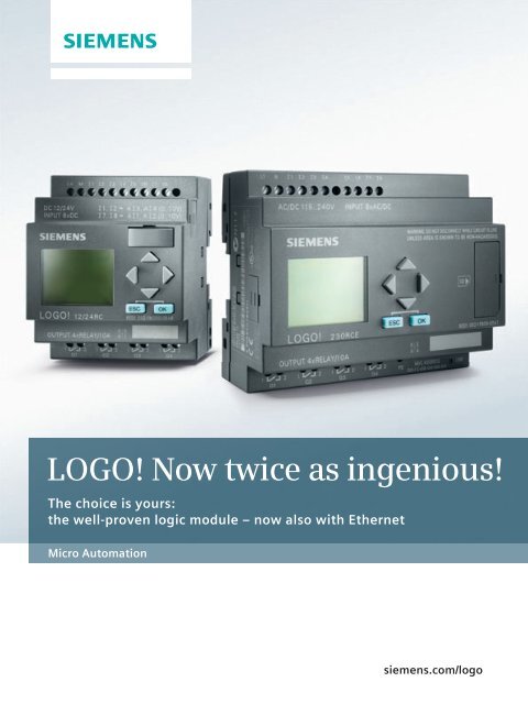
<strong>LOGO</strong>! Now twice as ingenious!<br />
The choice is yours:<br />
the well-proven logic module – now also with Ethernet<br />
Micro Automation<br />
siemens.com/logo
In infrastructure ...<br />
Heating / ventilation / air-conditioning<br />
■ Energy management<br />
■ Heating<br />
■ Cooling systems<br />
■ Ventilation systems<br />
■ Air-conditioning systems<br />
Building management systems<br />
■ Light control (outdoor and indoor<br />
lighting)<br />
■ Door/gate control<br />
■ Roller blind and awning control<br />
■ Irrigation and sprinkler systems<br />
Monitoring equipment<br />
■ Access controls<br />
■ Monitoring of drive controls<br />
■ Alarm systems<br />
■ Limit value checks<br />
■ Traffic light controllers<br />
■ Luggage inspection<br />
Profitable switching and controlling<br />
In automation, all of the potential means of savings<br />
must be consistently used – from planning and commissioning<br />
to operation. What is needed are systems<br />
that allow the constantly increasing requirements<br />
to be quickly and economically fulfilled: Intelligent<br />
solutions that stand out due to maximum flexibility,<br />
reliability, and user-friendliness. The best example of<br />
innovative technology that completely fulfills these<br />
high requirements is <strong>LOGO</strong>! – the world‘s leading logic<br />
module for switching and controlling.<br />
Intelligent technology with a vision<br />
<strong>LOGO</strong>! is ideally suited for implementing simple automation<br />
tasks in industry and building management systems.<br />
The intelligent logic module is characterized by maximum<br />
user-friendliness and it leaves little to be desired in<br />
terms of functionality, thanks in no small part to the high<br />
memory capacity and efficient use of memory. With the<br />
use of expansion modules, <strong>LOGO</strong>! can control even the<br />
most complex plants without any problems.<br />
Maximum flexibility due to consistent modularity<br />
A wide range of modules make it possible to individually<br />
expand <strong>LOGO</strong>! to 24 digital inputs, 16 digital outputs,<br />
8 analog inputs, and two analog outputs. Communication<br />
modules for AS-Interface and KNX are also available.<br />
With the analog output module, for example, you can<br />
solve simple control tasks. This is supported by the special<br />
functions of PI controller, ramp function, and analog<br />
multiplexing.<br />
2
... and industry<br />
Transport equipment<br />
■ Conveyor belts<br />
■ Lifting platforms<br />
■ Lifts<br />
■ Silo systems<br />
■ Automatic feeders<br />
Special solutions<br />
■ Solar plants<br />
■ Use on ships<br />
■ Use in extreme ambient conditions<br />
■ Display panels and traffic signboards<br />
Machine controls<br />
■ Motors, pump and valve controls<br />
■ Air compressors<br />
■ Extraction and filtering installations<br />
■ Sewage plants<br />
■ Sawing and planing machines<br />
■ Etching and cleaning equipment<br />
Tried and tested millions of times –<br />
in numerous applications<br />
In combination with the <strong>LOGO</strong>! software Soft Comfort,<br />
the handling of our logic module is child’s play: Creating<br />
programs, project simulating and documentation<br />
are quite easy using drag & drop – for maximum userfriendliness.<br />
In addition, a display with the capability of<br />
directly changing process parameters in the message text<br />
always ensures professional handling and satisfied users.<br />
All of this is the reason why <strong>LOGO</strong>! has proven itself over<br />
the past 15 years in millions of machine and building<br />
appli cations around the world.<br />
Whether in infrastructure<br />
or industry – a quick and<br />
cost-effective solution<br />
New applications made possible<br />
by new 0BA7 basic units<br />
The performance of <strong>LOGO</strong>! can be expanded in terms of<br />
the number of I/Os and program capacity by means of<br />
simple networking. It is not always necessary to switch<br />
to more complex PLC configurations for simple networking<br />
requirements. Instead, you can remain in the familiar,<br />
simple configuration world of our logic module and<br />
continue networking easily and cost-effectively. Even in<br />
a single family home, there are so many possible applications<br />
that the number of I/Os is exceeded by a single<br />
<strong>LOGO</strong>!. The simple networking via Ethernet is useful here.<br />
The new communication options via Ethernet now allow<br />
small <strong>LOGO</strong>! networks to be set up – as well as communication<br />
with higher-level systems.<br />
3
Easy expansion<br />
by means<br />
of a text<br />
display or<br />
expansion<br />
modules<br />
for a reliable<br />
solution<br />
<strong>LOGO</strong>! – simple, brilliant, reliable<br />
<strong>LOGO</strong>! 0BA6 basic units, together with the expansion<br />
modules and the external text display, provide a<br />
broad and proven basis for reliable solutions in<br />
mechanical engineering and building management<br />
<strong>LOGO</strong>! in assemblies with<br />
the function modules<br />
systems. Practice-oriented function blocks are easily<br />
connected via the software using the cursor and<br />
their interaction can be immediately tested.<br />
The simplest connection<br />
4
Outstanding performance and overview<br />
With <strong>LOGO</strong>! four of the eight digital inputs that are available<br />
on the hardware can be used as analog inputs and<br />
four as high-speed counter inputs up to a frequency of<br />
5 kHz. With a program memory for 200 function blocks,<br />
the 12/24 V DC devices provide sufficient capacity for many<br />
stand-alone applications. Up to 50 four-line message texts<br />
with a maximum of 32 characters per line ensure userfriendliness<br />
in practice and clearly display all of the relevant<br />
machine parameters. Well-conceived options such as<br />
ticker text, bar graph or status parameter also contribute<br />
to the user-friendliness. Function blocks for arithmetic and<br />
pulse width modulation open up further usage options.<br />
Last but not least: the Teleservice option, which often<br />
does away with costly on-site service calls and really pays<br />
off if you sell your systems cross-regionally.<br />
Additional text display<br />
<strong>LOGO</strong>! allows an additional text display, which is perfectly<br />
tailored to the needs of a logic module, to be connected.<br />
It is directly connected to the <strong>LOGO</strong>! without a communication<br />
module. The configuration is done using the same<br />
function block as for the internal display. You decide<br />
whether message texts are displayed on the internal or<br />
external display – or on both.<br />
Highlights of <strong>LOGO</strong>!<br />
■ Can be modularly expanded up to 50 I/Os<br />
■ 230 V units can be expanded with analog modules<br />
■ All three phases can be combined in a configuration<br />
■ Extremely simple software<br />
■ Display of up to 50 messages, either by LC display on<br />
the module, external TD, or both together<br />
■ Supports 12 or 16 standard characters per line,<br />
depending on the selected character set; you can<br />
double the number of characters with the ticker<br />
function<br />
■ Users can toggle between 2 languages<br />
■ Display of up to 4 bar charts and up to 4 I/O<br />
status parameters per message<br />
■ Controllable backlight of both displays can also be<br />
used in continuous operation<br />
■ Password protection for STOP mode on TD<br />
5
<strong>LOGO</strong>! – and now also with Ethernet<br />
<strong>LOGO</strong>! 0BA7 impressively proves that we are constantly<br />
further developing our pioneering logic<br />
module. The two new basic devices supplement the<br />
existing 0BA6 basic devices, which have already<br />
been tried and tested worldwide.<br />
Proven devices have been consistently further<br />
developed<br />
The developmental leap forward can even be seen on the<br />
outside of our new <strong>LOGO</strong>! 0BA7 basic devices: They are<br />
wider by two modular widths and the previous interface<br />
has been replaced by an Ethernet interface on the underside<br />
of the device.<br />
In addition, there is a slot for SD cards on the right front<br />
of the device. In spite of these exterior changes, the new<br />
devices are compatible with all existing I/O modules. Even<br />
programs from the previous <strong>LOGO</strong>! generations can be<br />
used in the new devices.<br />
The highlight of the 0BA7 basic devices is without a doubt<br />
the standard Ethernet interface. It is used as a programming<br />
interface and for communicating with other <strong>LOGO</strong>!<br />
0BA7 basic devices or SIMATIC automation components<br />
such as SIMATIC S7 CPUs, HMI Panels, and PCs. Up to<br />
eight <strong>LOGO</strong>! devices can be networked via the Ethernet<br />
interface.<br />
6
Standard Ethernet<br />
interface for<br />
communication<br />
with further <strong>LOGO</strong>!<br />
basic units or<br />
other automation<br />
components<br />
New communication options<br />
The networking is mainly used for direct communication between<br />
several <strong>LOGO</strong>! devices. The advantages that result from this:<br />
■ Increasing the number of I/Os in a configuration. One logic<br />
module executes the program and the others only serve as an<br />
I/O expansion – without processing their own program. This<br />
means that a multi-cell layout in the control cabinet is now also<br />
possible.<br />
■ Expansion of the program memory. All logic modules process<br />
their own program and only exchange some of the data among<br />
each other.<br />
Function extensions<br />
– Program memory extended to 400 function blocks<br />
– Astronomical time switch<br />
– Min./Max. function<br />
– Mean value generation<br />
– Analog filter<br />
– Stopwatch<br />
– Macro and library function<br />
– Data logging<br />
7
<strong>LOGO</strong>! Software – simply professional<br />
<strong>LOGO</strong>! Soft Comfort – stands for sensationally easy<br />
and quick configuration. This allows the creation<br />
of ladder and function block diagrams by selecting<br />
the respective functions and their connection via<br />
drag & drop. In addition, the entire switching<br />
program can be simulated and tested offline on the<br />
PC. Also possible: an online test in both program<br />
displays during operation. Last but not least, <strong>LOGO</strong>!<br />
Soft Comfort provides professional documentation<br />
with all of the necessary project information such<br />
as switching programs, comments, and parameter<br />
settings.<br />
A decisive argument for <strong>LOGO</strong>!<br />
<strong>LOGO</strong>! Soft Comfort is appealing in every respect. The<br />
user-friendliness of our software is unequaled on the market.<br />
The preferential configuration in the function block<br />
diagram is more manageable than in the contact diagram,<br />
especially for programs with many special functions.<br />
<strong>LOGO</strong>! Soft Comfort, however, allows programming in<br />
both display formats and the execution of online tests –<br />
as the only software in the logic module class. Since it can<br />
be executed on three operating system platforms, you will<br />
benefit from maximum flexibility when choosing a computer<br />
and a high-end device is not absolutely essential.<br />
The standard simulation function makes program development<br />
easy. You can immediately simulate, optimize and then<br />
group individual program sections for total functionality.<br />
The outstanding functionality of our software is rounded<br />
out by professional tools for creating the user documentation.<br />
A context-sensitive help function brings additional advantages:<br />
It puts an end to the tiresome business of paging<br />
through manuals and reduces the weight of your luggage<br />
when making service calls. Last but not least, an integrated<br />
tutorial and numerous examples facilitate your entry into<br />
modern automation technology.<br />
8
1 Create 2 Simulate 3 Online test 4 Document<br />
1 4<br />
2<br />
3<br />
<strong>LOGO</strong>!<br />
NEW<br />
■ Astronomical time switch<br />
■ Min./Max. function<br />
■ Mean value generation<br />
■ Analog filter<br />
■ Stop watch<br />
More functions ...<br />
With the current version of <strong>LOGO</strong>! Soft Comfort, you<br />
can, of course, easily configure all of the new <strong>LOGO</strong>!<br />
hardware and firmware functions.<br />
The following five function blocks have been added:<br />
■ Astronomical time switch<br />
■ Min./Max. function<br />
■ Mean value generation<br />
■ Analog filter<br />
■ Stop watch<br />
Sensationally<br />
easy and quick<br />
programming thanks to<br />
43 function blocks and<br />
operating via drag & drop<br />
... and important innovations<br />
Creating macro blocks<br />
with library function<br />
Recurring parts of programs can be saved separately as<br />
complete blocks and used in other programs. You can<br />
build up your own block library from regularly used partial<br />
applications and quickly and easily integrate them into<br />
new projects. This speeds up testing and programming.<br />
Data logging<br />
Data from the production process can be saved in the internal<br />
memory of the <strong>LOGO</strong>! or on a standard SD card in order<br />
to either read it with a PC or evaluate it from the SD card at<br />
the workstation.<br />
Networking<br />
A real highlight of the <strong>LOGO</strong>! 0BA7 generation are the<br />
different communication modes:<br />
■ Communication between <strong>LOGO</strong>! and <strong>LOGO</strong>! – the<br />
second <strong>LOGO</strong>! functions as an I/O expansion without<br />
its own program.<br />
■ Communication between <strong>LOGO</strong>! and <strong>LOGO</strong>! –<br />
the second <strong>LOGO</strong>! executes its own program and<br />
exchanges some data with the other one.<br />
■ Communication between <strong>LOGO</strong>! and SIMATIC S7 CPUs<br />
or Panels, which provide S7 communication via<br />
Ethernet.<br />
9
<strong>LOGO</strong>! – the proven basic units ...<br />
<strong>LOGO</strong>! impresses customers due to the wide variety of possible<br />
applications and it allows the easy implementation of compre hensive<br />
applications – last but not least due to the possibility of selecting<br />
from among 38 integrated functions and linking them to up to<br />
200 blocks. When operating and monitoring, the 4-line backlit<br />
display with a maximum of 32 characters per line ensures a high<br />
degree of user-friendliness. The message text allows the display of<br />
text, setpoints and actual values, bar graphs and status parameters.<br />
Of course, parameters can be adjusted in the message text.<br />
Flexibility is always assured due to the diverse expansion options.<br />
10
... and the new ones with Ethernet<br />
You have grown with <strong>LOGO</strong>! and you want to always be able to solve<br />
more tasks with a greater demand on industrial communication?<br />
Then, the new <strong>LOGO</strong>! 0BA7 devices are the ideal solution for you.<br />
With the new basic devices, you can easily expand old programs<br />
by adding functions.<br />
Also possible: the supplementing of additional I/Os or the integration<br />
of a user-friendly operator guidance via touch panels. Previously<br />
developed <strong>LOGO</strong>! programs can be used as a basis and the easy<br />
configuration continues.<br />
<strong>LOGO</strong>!<br />
simply ingenious –<br />
and now …<br />
11
<strong>LOGO</strong>! functions<br />
<strong>LOGO</strong>! pays off<br />
With the eight basic functions and 30 special functions, simple<br />
switching programs can be created quickly – either directly on<br />
the device or via PC. You can find a large selection of example<br />
applications under www.siemens.com/logo<br />
The eight basic functions<br />
AND (and) series<br />
connection NO<br />
contact<br />
NAND (and not)<br />
parallel connection<br />
NC contact<br />
AND with edge<br />
evaluation<br />
(pos. edge)<br />
NAND (and not)<br />
with edge evaluation<br />
(neg. edge)<br />
OR (or) parallel<br />
connection NO<br />
contact<br />
NOR (or not)<br />
series connection<br />
NC contact<br />
XOR (exclusive or)<br />
2-way changeover<br />
NOT (not)<br />
inverter<br />
Up to 50% cost savings<br />
■ Replaces many conventional switching<br />
devices<br />
■ Requires less space in the control cabinet<br />
■ Fewer accessories<br />
■ Less storage space<br />
■ Saves on servicing costs because it is free<br />
of wear<br />
Up to 70% time savings<br />
■ Simply snap it onto a standard<br />
mounting rail<br />
■ Low wiring overhead<br />
■ Simple programming using <strong>LOGO</strong>!<br />
Soft Comfort<br />
■ Use ready-to-use sample programs at<br />
no cost or create and test them on the PC<br />
and quickly transfer them free of errors<br />
■ Automatic daylight-saving adjustment<br />
■ Documentation<br />
Up to 70% space savings<br />
■ 4/6 modular widths suffice as a replacement<br />
for many relays, time switches, and<br />
contactor relays<br />
■ 8 basic and 30/35 special functions<br />
replace many conventional switching<br />
devices<br />
Universally applicable<br />
■ Vibration-proof<br />
■ High electromagnetic compatibility (EMC)<br />
■ Fully industrial-grade<br />
■ For all climatic conditions<br />
■ Radio suppression class B<br />
■ All of the required certifications for<br />
worldwide use<br />
■ Marine approval<br />
The special functions<br />
ON<br />
delay<br />
OFF<br />
delay<br />
ON/OFF<br />
delay<br />
Latching ON<br />
delay<br />
Interval relay/<br />
Pulse output<br />
Interval relay,<br />
edge-triggered<br />
Pulse generator<br />
12<br />
*Binary inputs of function blocks can be negated directly
<strong>LOGO</strong>! basic units 0BA6 <strong>LOGO</strong>! text display <strong>LOGO</strong>! basic units 0BA7<br />
<strong>LOGO</strong>! basic unit 0BA6<br />
■ 38/43 ready-to-use functions integrated – no<br />
additional devices such as operating hours<br />
counter required<br />
■ Linking of 200/400 functions possible<br />
■ 8 digital inputs (incl. 4 AI with 12/24 V DC)<br />
and 4 digital outputs on board<br />
■ Flexibly expandable up to 24 DI, 16 DO, 8 AI,<br />
and 2 AO<br />
■ Display of message texts, actual and setpoint<br />
values and direct modification of the values<br />
on the display (not on Pure variants)<br />
■ Integrated data retentivity – ensures backup<br />
of the current values in the event of a power<br />
failure<br />
■ Software <strong>LOGO</strong>! Soft Comfort V 7 for the userfriendly<br />
creation of switching programs on the<br />
PC for all <strong>LOGO</strong>! generations, which can run<br />
on various operating systems<br />
Random<br />
Staircase lighting<br />
timer<br />
Convenience<br />
switch<br />
Week time<br />
switch<br />
Year time<br />
switch<br />
Up/down<br />
counter<br />
Operating hours<br />
counter<br />
Threshold<br />
switch<br />
13
Digital expansion modules<br />
<strong>LOGO</strong>! basic unit 0BA7<br />
■ Standard Ethernet interface as<br />
programming interface and for<br />
communication with other <strong>LOGO</strong>!<br />
basic devices 0BA7 or SIMATIC<br />
automation components such<br />
as SIMATIC S7 CPUs, HMI Panels<br />
and PCs<br />
■ A maximum of 8 <strong>LOGO</strong>!s can<br />
be networked<br />
■ Data logging<br />
■ Standard SD cards as the<br />
storage medium<br />
■ Program and connectioncompatible<br />
with <strong>LOGO</strong>! 0BA6<br />
<strong>LOGO</strong>!<br />
simply<br />
twice as<br />
ingenious<br />
Analog<br />
comparator<br />
Analog threshold<br />
switch<br />
Analog amplifier<br />
Analog<br />
monitoring<br />
Analog difference<br />
threshold switch<br />
Latching<br />
relay<br />
Current impulse<br />
relay<br />
Software<br />
switch<br />
14
Analog expansion modules<br />
Communication modules<br />
NEW for 0BA7<br />
Astronomical<br />
time switch<br />
<strong>LOGO</strong>! modules<br />
Min./Max. function<br />
<strong>LOGO</strong>! text display<br />
For operator prompting and servicing for the<br />
display of message texts, input and output<br />
statuses, and for setting process parameters<br />
(usable as of basic device 0BA6, supports the<br />
range of functions of the 0BA6 basic devices)<br />
■ Display of up to 50 messages<br />
■ Users can toggle between 2 languages<br />
■ Display of up to 4 bar charts and up to<br />
4 I/O status parameters per message<br />
■ Supports max. 32 Standard characters<br />
per line<br />
■ Controllable backlight<br />
■ Password protection for RUN/STOP mode<br />
on TD<br />
Digital expansion modules*<br />
■ Expansion of the digital inputs and<br />
outputs:<br />
DM8 230R / DM16 230R<br />
DM8 24 / DM16 24<br />
DM8 12 / 24R<br />
DM8 24R<br />
DM16 24R<br />
Analog expansion modules*<br />
■ Expansion of the analog inputs:<br />
AM2 for 0–10 V or 0/4 ... 20 mA signals<br />
AM2 RTD for Pt100 or Pt1000<br />
with automatic sensor detection<br />
AM2 AQ for 0–10 V or 0/4 ... 20 mA signals<br />
Communication modules*<br />
■ CM AS-Interface slave<br />
– 4 DI/4 DO as interface to the AS-Interface<br />
master<br />
■ CM EIB / KNX<br />
– max. 16 DI, 12 DO, 8 AI and 8 AO as interface<br />
to the KNX<br />
– The date and time can be synchronized<br />
via KNX<br />
– All of the digital and analog input and output<br />
signals are available as communication<br />
objects on the KNX<br />
– Dimming and shutter/blind actuators on<br />
the KNX can be controlled in a systemconformant<br />
way<br />
Mean value generation<br />
Analog filter<br />
Stopwatch<br />
*All expansion modules are available for 0BA6 and 0BA7.<br />
Shift register<br />
PI controller<br />
Ramp function<br />
Analog<br />
multiplexer<br />
Message text<br />
expanded<br />
Arithmetic<br />
function<br />
Pulse width<br />
modulation<br />
15
<strong>LOGO</strong>! 0BA7– more options in detail<br />
With an Ethernet interface and SD card slot, <strong>LOGO</strong>!<br />
0BA7 opens up completely new perspectives – not only<br />
in terms of communication capabilities. The standard<br />
SD cards can be used – e.g. to copy programs or save<br />
data/projects with comments. In addition, the program<br />
memory has been expanded to 400 function blocks<br />
and, in place of the optional battery, the internal<br />
buffering of the real-time clock has been extended to<br />
20 days.<br />
Communication like never before<br />
Devices with an “E” in their names can communicate with<br />
each other via Ethernet. This can happen in various ways:<br />
■ Master/slave connections<br />
between <strong>LOGO</strong>! and <strong>LOGO</strong>!<br />
In this case, only one of a maximum of 8 basic devices<br />
processes a user program. The others only serve<br />
to expand the I/O capacity. They provide the input<br />
information of the digital and analog inputs to the first<br />
<strong>LOGO</strong>! and execute the switching commands on the<br />
other side for the digital outputs of their hardware, or<br />
they forward the analog output values to the I/O. This<br />
does away with the limitation on the number of channels<br />
of the previous basic devices. Of course, the basic<br />
devices that are being used as slaves can be equipped<br />
with the proven expansion modules up to the maximum<br />
process image.<br />
16
■ Master/master connections<br />
between <strong>LOGO</strong>! and <strong>LOGO</strong>!<br />
In this mode, up to 8 basic devices can also be connected<br />
to each other. However, each <strong>LOGO</strong>! processes<br />
its own program and shares only the generally needed<br />
information with the others. In this way, small, networked<br />
systems with easy program structures can be<br />
created. Each unit can continue to solve its subtask<br />
without the others, if necessary.<br />
In both cases, up to 8 basic devices and a PC/PG for<br />
programming can be interconnected. The theoretical<br />
degree of expansion of a <strong>LOGO</strong>! configuration is thus<br />
192 DI, 128 DO, 64 AO, and 16 AO.<br />
■ Communication with SIMATIC S7<br />
The new <strong>LOGO</strong>! basic modules can be coupled to higherlevel<br />
automation structures (e.g. SIMATIC S7 CPUs or<br />
HMI Panels with Ethernet interface), because they can<br />
work with the standard S7 protocol. This allows, for<br />
example, the use of SIMATIC Touch Panels for operating<br />
a machine controlled by <strong>LOGO</strong>!. Of course, you can also<br />
combine these communication options as needed.<br />
Twice the program memory and<br />
five new function blocks<br />
The five new function blocks pay off in practice. Thus, for<br />
example, minimum and maximum temperature values can<br />
be determined over the course of a day or mean values<br />
can be formed over a defined period of time. The duration<br />
of any process can be measured using a stopwatch. In<br />
addition, there is an astronomical time switch, which can<br />
be used for such things as controlling outside lighting or<br />
feeding times in animal husbandry, and an analog filter,<br />
which helps to smooth the influence of interference<br />
pulses on the signal profile. Last but not least, the number<br />
of usable shift registers has been increased to four. Thus,<br />
shift registers with up to 32 bits are now possible.<br />
Completely new perspectives<br />
for communication,<br />
data handling and storage<br />
17
Increased engineering efficiency: reusable sections<br />
of a program<br />
More complex applications can be programmed using<br />
<strong>LOGO</strong>! Soft Comfort V7 even easier than before: Macros<br />
can now be used and libraries can be created for recurring<br />
program sequences (e.g. for roller blind controllers).<br />
Corresponding program sections can then be selected<br />
and reused at any time. When opening a program that<br />
contains macros from the library, you are notified if the<br />
macro has been changed since its last use. Macros are<br />
also helpful when creating step sequence controls.<br />
New usage options thanks to data logging<br />
Thanks to data logging, you can now save specific production<br />
or process data in a data area in the <strong>LOGO</strong>! –<br />
either by using the internal memory or by using a standard<br />
SD card up to 4 GB. This is advantageous if <strong>LOGO</strong>! is<br />
used for controlling temperatures or monitoring levels,<br />
for example. Corresponding characteristics can be easily<br />
documented and evaluated. In the program, the user can<br />
define the time intervals in which or the event by which<br />
the temperature data or levels are to be recorded.<br />
18
Simply more –<br />
many more<br />
options in<br />
every respect<br />
New advantages, old strengths<br />
The status of the inputs and outputs are transferred to the<br />
PC via the Ethernet interface and are documented there<br />
in an Excel table, for example. However, the new software<br />
also facilitates programming for users of the previous<br />
<strong>LOGO</strong>!: Function blocks can be exchanged without having<br />
to create new connections. The simplified handling includes<br />
additional capabilities for aligning the blocks and<br />
the additional linking of comments.<br />
Of course, the new generation of devices are also<br />
characterized by the proven strengths of <strong>LOGO</strong>!: from the<br />
flexible, modular design and easy creation of programs,<br />
project simulation and documentation by means of<br />
drag & drop to the built-in display with HMI functionality.<br />
The new basic devices are fully compatible with the old<br />
ones, apart from the increased width of the devices<br />
(108 mm instead of 72 mm), which is due to the implemented<br />
innovations. They have the built-in display, cursor<br />
keys, and the familiar signal ports. Therefore, with their<br />
expanded functionality, they can completely replace the<br />
old 0BA6 basic devices.<br />
In addition, all of the old expansion modules can be used<br />
on the new basic devices without restrictions. The only<br />
thing that must be noted is that an Ethernet cable is required<br />
in order to directly transfer an existing program<br />
from one PC to one of the new basic devices.<br />
19
<strong>LOGO</strong>! modular – the technical details<br />
Basic units <strong>LOGO</strong>! 12/24RC 1) , <strong>LOGO</strong>! 12/24RCo 2) <strong>LOGO</strong>! 24C, <strong>LOGO</strong>! 24Co <strong>LOGO</strong>! 24RC 1) , <strong>LOGO</strong>! 24RCo 2)<br />
Inputs 8 8 8<br />
of which can be used in analog mode 4 (0 to 10 V) 4 (0 to 10 V) –<br />
Input/supply voltage 12/24 V DC 24 V DC 24 V AC/DC<br />
Permissible range<br />
with signal “0”<br />
with signal “1”<br />
Input current<br />
10.8 V ... 28.8 V DC<br />
max. 5 V DC<br />
min. 8.5 V DC<br />
1.5 mA (Ι3 ... Ι6), 0.1 mA (Ι 1, Ι 2, Ι 7, Ι 8)<br />
20.4 V ... 28.8 V DC<br />
max. 5 V DC<br />
min. 12 V DC<br />
2 mA (Ι3 ... Ι6), 0.1 mA (Ι 1, Ι 2, Ι 7, Ι 8)<br />
20.4 ... 28.8 V DC<br />
20.4 ... 26.4 V AC<br />
max. 5 V AC/DC<br />
min. 12 V AC/DC, 2.5 mA<br />
Outputs 4 relays 4 transistors 4 relays<br />
Continuous current<br />
10 A with resistive load;<br />
3 A with inductive load<br />
0.3 A 10 A with resistive load;<br />
3 A with inductive load<br />
Short-circuit protection External fuse required Electronic (approx. 1 A) External fuse required<br />
Switching frequency<br />
2 Hz with resistive load;<br />
0.5 Hz with inductive load<br />
10 Hz 2 Hz with resistive load;<br />
0.5 Hz with inductive load<br />
Cycle time < 0.1 ms/function < 0.1 ms/function < 0.1 ms/function<br />
Integrated time switches/<br />
power reserve<br />
Yes / typ. 80 h<br />
(2 years with battery module)<br />
Yes / typ. 80 h<br />
(2 years with battery module)<br />
Yes / typ. 80 h<br />
(2 years with battery module)<br />
Connection cables 2 x 1.5 mm 2 or 1 x 2.5 mm 2<br />
Ambient temperature 0 to + 55 ºC<br />
Storage temperature – 40 ºC to + 70 ºC<br />
Emitted interference In accordance with EN 55011 (limit class B)<br />
Degree of protection IP20<br />
Certification<br />
In accordance with VDE 0631, IEC 1131, FM Class 1, Div 2, cULus, C-Tick, marine approvals<br />
Mounting<br />
On 35 mm standard mounting rail, 4 MW, or wall-mounting<br />
Dimensions 72 (4 MW) x 90 x 55 mm (W x H x D)<br />
Programming cable <strong>LOGO</strong>! PC cable, (RS232 or USB) <strong>LOGO</strong>! PC cable, (RS232 or USB) <strong>LOGO</strong>! PC cable, (RS232 or USB)<br />
Optional backup battery Yes Yes Yes<br />
<strong>LOGO</strong>! <strong>LOGO</strong>!<br />
No No No<br />
communication (Ethernet)<br />
<strong>LOGO</strong>! network No No No<br />
(Ethernet)<br />
Maximum<br />
200 blocks 200 blocks 200 blocks<br />
program memory<br />
External memory module <strong>LOGO</strong>! memory card <strong>LOGO</strong>! memory card <strong>LOGO</strong>! memory card<br />
Data logging No No No<br />
Online status chart No No No<br />
Macro function No No No<br />
Digital modules <strong>LOGO</strong>! DM8 12/24R <strong>LOGO</strong>! DM8 24<br />
DM16 24<br />
Inputs 4 4/8<br />
Input/supply voltage 12/24 V DC 24 V DC<br />
Permitted range 10.8 ... 28.8 V DC 20.4 ... 28.8 V DC<br />
with signal “0”<br />
with signal “1”<br />
max. 5 V DC<br />
min. 5 V DC 8.<br />
max. 5 V DC<br />
min. 12 V DC<br />
Input current 1.5 mA 2 mA<br />
Outputs 4 relays 4/8 transistors<br />
Continuous current Ith (per terminal)<br />
5 A with resistive load;<br />
0.3 A<br />
3 A with inductive load<br />
Short-circuit protection External fuse required Electronic (approx. 1 A)<br />
Switching frequency<br />
2 Hz with resistive load;<br />
10 Hz<br />
0.5 Hz with inductive load<br />
Power loss<br />
0.3 ... 1.7 W at 12 V DC<br />
0.4 ... 1.8 W at 24 V DC<br />
0.8 ... 1.1 W*<br />
0.8 ... 1.7 W**<br />
Dimensions (W x H x D) 36 (2 MW) x 90 x 53 mm 36 (2 MW) x 90 x 53 mm<br />
72 (4 MW) x 90 x 53 mm
<strong>LOGO</strong>! 230RC 1) , <strong>LOGO</strong>! 230RCo 2) <strong>LOGO</strong>! 12/24 RCE <strong>LOGO</strong>! 230 RCE<br />
8 8 8<br />
– 4 (0 to 10 V) –<br />
115/240 V AC/DC 12/24 V DC 115/240 V AC/DC<br />
85 ... 265 V AC<br />
100 ... 253 V DC<br />
max. 40 V AC/30 V DC<br />
min. 79 V AC/79 V DC, 0.08 mA<br />
10.8 V ... 28.8 V DC<br />
max. 5 V DC<br />
min. 8.5 V DC<br />
1.5 mA (I3 ... I6) 0.1 mA (I 1, I 2, I 7, I 8)<br />
4 relays 4 relays 4 relays<br />
10 A with resistive load;<br />
3 A with inductive load<br />
10 A with resistive load;<br />
3 A with inductive load<br />
85 ... 265 V AC<br />
100 ... 253 V DC<br />
max. 40 V AC/30 V DC<br />
min. 79 V AC/79 V DC, 0.08 mA<br />
10 A with resistive load;<br />
3 A with inductive load<br />
External fuse required External fuse required External fuse required<br />
2 Hz with resistive load;<br />
0.5 Hz with inductive load<br />
2 Hz with resistive load;<br />
0.5 Hz with inductive load<br />
2 Hz with resistive load;<br />
0.5 Hz with inductive load<br />
< 0.1 ms/function < 0.1 ms/function < 0.1 ms/function<br />
Yes / typ. 80 h (2 years with battery module) Typically 20 days; no battery Typically 20 days; no battery<br />
On 35 mm standard mounting rail, 6 MW, or wall-mounting<br />
108 (6 MW) x 90 x 55 mm (W x H x D) 108 (6 MW) x 90 x 55 mm (W x H x D)<br />
<strong>LOGO</strong>! PC cable, (RS232 or USB) Ethernet Ethernet<br />
Yes No No<br />
No Yes, max. 8 <strong>LOGO</strong>!s + 1PC/PG Yes, max. 8 <strong>LOGO</strong>!s + 1PC/PG<br />
No<br />
Yes, max. 8 TN<br />
(<strong>LOGO</strong>!, SIMATIC CPU, 1x SIMATIC HMI, PC)<br />
200 blocks 400 blocks 400 blocks<br />
<strong>LOGO</strong>! memory card<br />
SIMATIC memory card or<br />
standard SD card max. 2 G<br />
Yes, max. 8 TN<br />
(<strong>LOGO</strong>!, SIMATIC CPU, 1x SIMATIC HMI, PC)<br />
SIMATIC memory card or<br />
standard SD card max. 2 G<br />
No Internal memory/SD card Internal memory/SD card<br />
No Yes, with saving on the PC Yes, with saving on the PC<br />
No Yes Yes<br />
<strong>LOGO</strong>! DM8 24R<br />
DM16 24R<br />
<strong>LOGO</strong>! DM8 230R<br />
DM16 230R<br />
4/8 4/8<br />
24 V AC/DC*<br />
115/240 V AC/DC<br />
24 V DC**<br />
20.4 ... 28.8 V DC, 20.4 ... 26.4 V AC* 85 ... 265 V AC, 100 ... 253 V DC<br />
max. 5 V AC/DC<br />
min. 12 V AC/DC*<br />
max. 40 V AC<br />
min. 79 V AC<br />
2.5 mA*, 2.0 mA** 0.08 mA<br />
4/8 relays 4/8 relays<br />
5 A with resistive load;<br />
3 A with inductive load<br />
External fuse required<br />
2 Hz with resistive load;<br />
0.5 Hz with inductive load<br />
0.4 ... 1.8 W at 24 V DC*<br />
0.9 ... 2.7 W at 24 V AC*<br />
0.7 ... 2.5 W at 24 V DC**<br />
36 (2 MW) x 90 x 53 mm<br />
72 (4 MW) x 90 x 53 mm<br />
5 A with resistive load;<br />
3 A with inductive load<br />
External fuse required<br />
2 Hz with resistive load;<br />
0.5 Hz with inductive load<br />
1.1 ... 3.5 W (115 V AC) ... 4.5**<br />
2.4 ... 4.8 W (240 V AC) ... 5.5**<br />
0.5 ... 1.8 W (115 V DC) ... 2.9**<br />
1.2 ... 2.4 W (240 V DC) ... 4.8**<br />
36 (2 MW) x 90 x 53 mm<br />
72 (4 MW) x 90 x 53 mm<br />
R: Relay outputs, C: Clock/time switch,<br />
o: without display.<br />
E: Ethernet interface<br />
* for DM8 module, ** for DM16 module<br />
1) As SIPLUS component also for extended temperature<br />
range – 25 ... +70 °C and corrosive atmosphere/<br />
condensation (www.siemens.com/siplus)<br />
2) As SIPLUS component also for extended temperature<br />
range – 40 ... +70 °C and corrosive atmosphere/<br />
condensation (www.siemens.com/siplus)<br />
21
<strong>LOGO</strong>! modular – the technical data<br />
Analog modules <strong>LOGO</strong>! AM2 2) <strong>LOGO</strong>! AM2 RTD <strong>LOGO</strong>! AM2 AQ 2)<br />
Supply voltage 12/24 V DC 12/24 V DC 24 V DC<br />
Permitted range 10.8 ... 28.8 V DC 10.8 ... 28.8 V DC 20.4 ... 28.8 V DC<br />
Analog inputs 2 2 x PT100 or PT1000<br />
2-wire or 3-wire<br />
Automatic sensor detection<br />
2<br />
Measuring range –50 ºC ... +200 ºC 0 ... 10 V<br />
Input range 0 ... 10 V or 0/4 ... 20 mA – 0 ... 10 V or 0/4 ... 20 mA<br />
Resolution 10 bit standardized to 0 – 1000 0.25 °C 10 bit standardized to 0 – 1000<br />
Cable length<br />
10 m 10 m 10 m<br />
(shielded and twisted)<br />
Encoder supply none 1.1 mA –<br />
Power loss<br />
at 12 V DC<br />
at 24 V DC<br />
0.3 ... 0.6 W<br />
0.6 ... 1.2 W<br />
0.3 ... 0.6 W<br />
0.6 ... 1.2 W<br />
–<br />
0.6 ... 1.2 W<br />
Dimensions (W x H x D) 36 (2 MW) x 90 x 53 mm 36 (2 MW) x 90 x 53 mm 36 (2 MW) x 90 x 53 mm<br />
2) as SIPLUS component also for extended temperature range<br />
– 40 ... + 70 °C and corrosive atmosphere/condensation (www.siemens.com/siplus)<br />
<strong>LOGO</strong>! TD Text Display<br />
Supply voltage<br />
Permitted range<br />
Input<br />
Display<br />
Lines/characters<br />
Length of connecting cable<br />
Power consumption at 24 V DC<br />
Cutout dimensions (W x H x D)<br />
12 V DC, 24 V AC/DC<br />
10.2 ... 28.8 V DC or 20.4 to 26.4 V AC (47 ... 63 Hz)<br />
6 standard keys, 4 function keys (tactile-touch keys)<br />
61 x 33 mm, white, controllable backlight, adjustable contrast<br />
4 lines, 12/16 characters per line (depends on character set)<br />
2.5 m (extendable to 10 m with “universal“ 9-wire standard serial cable)<br />
typ. 65 mA (12 V DC), typ. 40 mA (24 V DC), typ. 90 mA (24 V AC)<br />
119.5 x 78.5 x 1.5 – 4.0 mm for panel mounting (128.3 x 86 x 38.7 mm total)<br />
Communication modules (CM) EIB / KNX CM AS-Interface (slave)<br />
Supply voltage 12/24 V DC 24 V DC<br />
Permitted range<br />
20.4 ... 28.8 V DC<br />
19.2 ... 28.8 V DC<br />
20.4 ... 26.4 V AC<br />
Digital inputs*<br />
16 (can also be configured 4<br />
as Monoflop)<br />
Analog inputs* 8 –<br />
Analog outputs* 2 (max. 8) –<br />
Digital outputs* 12 4<br />
Dimensions (W x H x D) 2 MW 36 x 90 x 53 mm 2 MW 36 x 90 x 53 mm<br />
* Mapping to <strong>LOGO</strong>! inputs/outputs<br />
22
<strong>LOGO</strong>!<br />
ordering data<br />
<strong>LOGO</strong>! versions<br />
<strong>LOGO</strong>! 12/24 RCE<br />
<strong>LOGO</strong>! 230 RCE<br />
<strong>LOGO</strong>! 24 C<br />
<strong>LOGO</strong>! 24 Co<br />
<strong>LOGO</strong>! 12/24RC<br />
<strong>LOGO</strong>! 12/24RCo<br />
<strong>LOGO</strong>! 24RC (AC/DC)<br />
<strong>LOGO</strong>! 24RC (AC/DC)<br />
<strong>LOGO</strong>! 230RC<br />
<strong>LOGO</strong>! 230RCo<br />
<strong>LOGO</strong>! TD<br />
Expansion modules<br />
<strong>LOGO</strong>! DM8 24<br />
<strong>LOGO</strong>! DM8 12/24R<br />
<strong>LOGO</strong>! DM8 24R (AC/DC)<br />
<strong>LOGO</strong>! DM8 230R<br />
<strong>LOGO</strong>! DM16 24<br />
<strong>LOGO</strong>! DM16 24R<br />
<strong>LOGO</strong>! DM16 230R<br />
<strong>LOGO</strong>! AM2<br />
<strong>LOGO</strong>! AM2 RTD<br />
<strong>LOGO</strong>! AM2 AQ<br />
Communication modules<br />
<strong>LOGO</strong>! AS-i<br />
<strong>LOGO</strong>! EIB / KNX<br />
Optional accessories<br />
<strong>LOGO</strong>! Manual German<br />
<strong>LOGO</strong>! Manual English<br />
<strong>LOGO</strong>! Memory Card<br />
<strong>LOGO</strong>! Battery Card<br />
<strong>LOGO</strong>! Combo Memory &<br />
Battery Card<br />
<strong>LOGO</strong>! Soft Comfort V 7.0<br />
<strong>LOGO</strong>! Soft Comfort V 7.0<br />
Upgrade<br />
<strong>LOGO</strong>! PC cable<br />
<strong>LOGO</strong>! USB PC cable<br />
<strong>LOGO</strong>! modem cable<br />
Order No.<br />
6ED1 052-1MD00-0BA7<br />
6ED1 052-1FB00-0BA7<br />
6ED1 052-1CC01-0BA6<br />
6ED1 052-2CC01-0BA6<br />
6ED1 052-1MD00-0BA6<br />
6ED1 052-2MD00-0BA6<br />
6ED1 052-1HB00-0BA6<br />
6ED1 052-2HB00-0BA6<br />
6ED1 052-1FB00-0BA6<br />
6ED1 052-2FB00-0BA6<br />
6ED1 055-4MH00-0BA0<br />
Order No.<br />
6ED1 055-1CB00-0BA0<br />
6ED1 055-1MB00-0BA1<br />
6ED1 055-1HB00-0BA0<br />
6ED1 055-1FB00-0BA1<br />
6ED1 055-1CB10-0BA0<br />
6ED1 055-1NB10-0BA0<br />
6ED1 055-1FB10-0BA0<br />
6ED1 055-1MA00-0BA0<br />
6ED1 055-1MD00-0BA1<br />
6ED1 055-1MM00-0BA2<br />
Order No.<br />
3RK1 400-0CE10-0AA2<br />
6BK1 700-0BA00-0AA2<br />
Order No.<br />
R: Relay outputs, C: Clock/time switch, o: without display<br />
6ED1 050-1AA00-0AE8<br />
6ED1 050-1AA00-0BE8<br />
6ED1 056-1DA00-0BA0<br />
6ED1 056-6XA00-0BA0<br />
6ED1 056-7DA00-0BA0<br />
6ED1 058-0BA02-0YA1<br />
6ED1 058-0CA02-0YE1<br />
6ED1 057-1AA00-0BA0<br />
6ED1 057-1AA01-0BA0<br />
6ED1 057-1CA00-0BA0<br />
The products listed here may be subject to the current European/German and/<br />
or US export regulations.<br />
<strong>LOGO</strong>! accessories<br />
<strong>LOGO</strong>! PC cables/USB PC cables (only 0BA6)<br />
For the simple transfer of <strong>LOGO</strong>! switching<br />
programs to and from PCs<br />
<strong>LOGO</strong>! program module (only 0BA6)<br />
For duplicating switching programs –<br />
and for protecting existing know-how<br />
• Also possible for 0BA7:<br />
commercially available SD card, up to 2 GB<br />
<strong>LOGO</strong>! Manual<br />
For intro to <strong>LOGO</strong>!<br />
• Detailed information on operation<br />
• Description of all integrated functions<br />
• Many practical application examples<br />
• Available in 10 languages<br />
<strong>LOGO</strong>! Power<br />
Reliable power supply for <strong>LOGO</strong>! – for converting<br />
the line voltage of 100/240 V AC to the respective<br />
operating voltage<br />
• Suitable for all <strong>LOGO</strong>! 12 V DC and 24 V DC<br />
• Versions for different output currents<br />
More information: www.siemens.com/sitop<br />
<strong>LOGO</strong>! Contact<br />
Hum-free switching module<br />
• For switching resistive loads up to 20 A<br />
• For the direct switching of motors up to 4 kW<br />
• For powerful loads in noise-sensitive areas<br />
More information:<br />
www.siemens.com/lowvoltage<br />
<strong>LOGO</strong>! Prom (only 0BA6)<br />
For replication of program modules<br />
• For copying of modules<br />
• For writing to modules via <strong>LOGO</strong>! Soft Comfort<br />
More information: www.siemens.com/siplus<br />
Front panel mounting frame<br />
For installation in the control cabinet door<br />
• Front IP65 (IP30 without glass)<br />
• 4 MW or 8 MW (optional with keys)<br />
More information: www.siemens.com/siplus<br />
<strong>LOGO</strong>! Upmitter<br />
For use with critical power supplies<br />
Produces stable 24 V DC at the output with<br />
8 to 59 V DC at the input<br />
More information: www.siemens.com/siplus<br />
23
Further information on <strong>LOGO</strong>!<br />
can be found on the Internet –<br />
under www.siemens.com/logo<br />
• Comprehensive product information<br />
• Free demonstration software<br />
• Software upgrades<br />
• Ready-to-use applications<br />
• News<br />
• Customer magazine GO!<br />
• And much more<br />
Of course, you can also purchase software, hardware<br />
or promotion packages for <strong>LOGO</strong>! online. In<br />
addition, on request you also find personal support<br />
under “Service and Support.” We have compiled<br />
further example applications and configuration tools<br />
for you under www.siemens.com/microset.<br />
SIPLUS <strong>LOGO</strong>! in the Internet<br />
www.siemens.com/siplus<br />
You can find hardened <strong>LOGO</strong>! modules there with<br />
• extended temperature range<br />
• Protection against corrosive atmosphere/<br />
condensation<br />
<strong>Siemens</strong> AG<br />
Industry Sector<br />
Industry Automation<br />
P.O. Box 48 48<br />
90026 NUREMBERG<br />
GERMANY<br />
Subject to change without prior notice 03/11<br />
Order No. E20001-A1120-P271-X-7600<br />
Dispo 06307<br />
WÜ/32480 MI.AS.LO.XXXX.52.1.02 03115.0<br />
Printed in Germany<br />
© <strong>Siemens</strong> AG 2011<br />
The information provided in this brochure contains me re ly general descriptions<br />
or characteristics of per for m ance which in ac tual case of use do not always<br />
ap ply as described or which may change as a result of fur ther de ve lopment<br />
of the pro ducts. An obligation to provide the respective characteristics shall<br />
only exist if ex pressly agreed in the terms of contract. All product designations<br />
may be trademarks or product na mes of <strong>Siemens</strong> AG or supplier companies<br />
whose use by third parties for their own purposes could violate the rights of<br />
the owners.


