

Altivar 71 - Schneider Electric
Altivar 71 - Schneider Electric
Altivar 71 - Schneider Electric

Create successful ePaper yourself
Turn your PDF publications into a flip-book with our unique Google optimized e-Paper software.
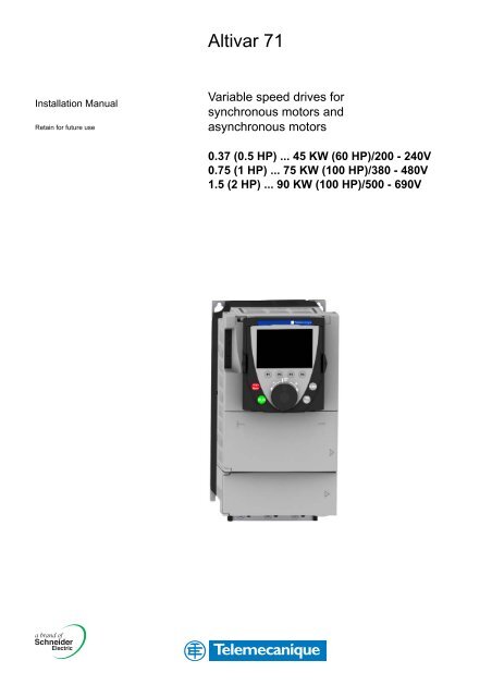
<strong>Altivar</strong> <strong>71</strong><br />
Installation Manual<br />
Retain for future use<br />
Variable speed drives for<br />
synchronous motors and<br />
asynchronous motors<br />
0.37 (0.5 HP) ... 45 KW (60 HP)/200 - 240V<br />
0.75 (1 HP) ... 75 KW (100 HP)/380 - 480V<br />
1.5 (2 HP) ... 90 KW (100 HP)/500 - 690V
Contents<br />
Important information __________________________________________________________________________________________ 4<br />
Before you begin______________________________________________________________________________________________ 5<br />
Steps for setting up the drive ____________________________________________________________________________________ 6<br />
Preliminary recommendations ___________________________________________________________________________________ 7<br />
Drive ratings _________________________________________________________________________________________________ 9<br />
Dimensions and weights_______________________________________________________________________________________ 12<br />
Mounting and temperature conditions ____________________________________________________________________________ 13<br />
Mounting in a wall-mounted or floor-standing enclosure ______________________________________________________________ 16<br />
Installing the graphic display terminal_____________________________________________________________________________ 18<br />
Position of the charging LED ___________________________________________________________________________________ 19<br />
Installing option cards_________________________________________________________________________________________ 20<br />
Installing the EMC plates ______________________________________________________________________________________ 22<br />
Wiring recommendations ______________________________________________________________________________________ 23<br />
Power terminals _____________________________________________________________________________________________ 25<br />
Control terminals_____________________________________________________________________________________________ 27<br />
Option terminals _____________________________________________________________________________________________ 29<br />
Connection diagrams _________________________________________________________________________________________ 35<br />
Use on IT system and corner grounded system_____________________________________________________________________ 44<br />
Electromagnetic compatibility, wiring _____________________________________________________________________________ 46<br />
3
Important information<br />
PLEASE NOTE<br />
Please read these instructions carefully and examine the equipment in order to familiarize yourself with the device before installing,<br />
operating or carrying out any maintenance work on it.<br />
The following special messages that you will come across in this document or on the device are designed to warn you about potential risks<br />
or draw your attention to information that will clarify or simplify a procedure.<br />
The addition of this symbol to a “Danger” or “Warning” safety label indicates that there is an electrical risk that will result<br />
in injury if the instructions are not followed.<br />
This is a safety warning symbol. It warns you of the potential risk of injury. You must comply with all safety messages that<br />
follow this symbol in order to avoid the risk of injury or death.<br />
DANGER<br />
DANGER indicates an imminently hazardous situation which, if not avoided, will result in death, serious injury or equipment<br />
damage.<br />
WARNING<br />
WARNING indicates a potentially hazardous situation which, if not avoided, can result in death, serious injury or equipment damage.<br />
PLEASE NOTE:<br />
CAUTION<br />
CAUTION indicates a potentially hazardous situation which, if not avoided, can result in injury or equipment damage.<br />
Only qualified personnel are authorized to carry out maintenance work on electrical equipment. <strong>Schneider</strong> <strong>Electric</strong> accepts no responsibility<br />
for the consequences of using this device. This document does not constitute an instruction manual for inexperienced personnel.<br />
© 2006 <strong>Schneider</strong> <strong>Electric</strong>. All rights reserved.<br />
4
Before you begin<br />
Read and understand these instructions before performing any procedure using<br />
this drive.<br />
DANGER<br />
RISK OF ELECTRIC SHOCK<br />
• Read and understand this manual before installing or operating the <strong>Altivar</strong> <strong>71</strong> drive.<br />
Installation, adjustment, repair, and maintenance must be performed by qualified<br />
personnel.<br />
• The user is responsible for compliance with all international and national electrical<br />
standards in force concerning protective grounding of all equipment.<br />
• Many parts in this variable speed drive, including printed wiring boards, operate at line<br />
voltage. DO NOT TOUCH.<br />
Use only electrically insulated tools.<br />
• DO NOT touch unshielded components or terminal strip screw connections with<br />
voltage present.<br />
• DO NOT short across terminals PA and PC or across the DC bus capacitors.<br />
• Install and close all the covers before applying power or starting and stopping<br />
the drive.<br />
• Before servicing the variable speed drive:<br />
- Disconnect all power.<br />
- Place a “DO NOT TURN ON” label on the variable speed drive disconnect.<br />
- Lock the disconnect in the open position.<br />
• Disconnect all power including external control power that may be present before<br />
servicing the drive. WAIT 15 MINUTES to allow the DC bus capacitors to discharge.<br />
Then follow the DC bus voltage measurement procedure on page 19 to verify that the<br />
DC voltage is less than 45 V. The drive LEDs are not accurate indicators of the<br />
absence of DC bus voltage.<br />
Failure to follow these instructions will result in death or serious injury.<br />
IMPROPER DRIVE OPERATION<br />
CAUTION<br />
• If the drive is not turned on for a long period, the performance of its electrolytic<br />
capacitors will be reduced.<br />
• If it is stopped for a prolonged period, turn the drive on every two years for at least<br />
5 hours to restore the performance of the capacitors, then check its operation. It is<br />
recommended that the drive is not connected directly to the line voltage. The voltage<br />
should be increased gradually using an adjustable AC source.<br />
Failure to follow these instructions can result in injury and/or equipment damage.<br />
5
Steps for setting up the drive<br />
INSTALLATION<br />
b 1 Receive and inspect the drive controller<br />
v Check that the catalog number printed on the label is the same<br />
as that on the purchase order<br />
v Remove the <strong>Altivar</strong> from its packaging and check that it has not<br />
been damaged in transit<br />
Steps 1 to 4 must<br />
be performed with<br />
the power off.<br />
b 2 Check the line voltage<br />
v Check that the line voltage is compatible with the<br />
voltage range of the drive (see pages 9 , 10 and 11)<br />
b 3 Mount the drive<br />
v Mount the drive in accordance with the instructions<br />
in this document<br />
v Install any internal and external options<br />
b 4 Wire the drive<br />
v Connect the motor, ensuring that its<br />
connections correspond to the voltage<br />
v Connect the line supply, after making sure<br />
that the power is off<br />
v Connect the control<br />
v Connect the speed reference<br />
PROGRAMMING<br />
v 5 Please refer to the<br />
Programming Manual<br />
6
Preliminary recommendations<br />
Handling and storage<br />
To protect the drive prior to installation, handle and store the device in its packaging. Ensure that the ambient conditions are acceptable.<br />
WARNING<br />
DAMAGED PACKAGING<br />
If the packaging appears damaged, it can be dangerous to open it or handle it.<br />
Take precautions against all risks when performing this operation.<br />
Failure to follow these instructions can result in death, serious injury or equipment damage.<br />
DAMAGED EQUIPMENT<br />
Handling on installation<br />
WARNING<br />
Do not install or operate any drive that appears damaged.<br />
Failure to follow this instruction can result in death, serious injury or equipment damage.<br />
45°<br />
max.<br />
ALTIVAR <strong>71</strong> drives up to ratings ATV<strong>71</strong>HD15M3X and ATV<strong>71</strong>HD18N4 can be removed<br />
from their packaging and installed without a handling device.<br />
A hoist must be used for higher ratings and for ATV<strong>71</strong>HpppY drives; for this reason,<br />
these drives all have lifting lugs. Follow the recommendations on the next page.<br />
7
Preliminary recommendations<br />
Precautions<br />
Read and understand the instructions in the Programming Manual.<br />
CAUTION<br />
INCOMPATIBLE LINE VOLTAGE<br />
Before turning on and configuring the drive, ensure that the line voltage is compatible with the supply voltage range shown<br />
on the drive nameplate. The drive may be damaged if the line voltage is not compatible.<br />
Failure to follow this instruction can result in injury and/or equipment damage.<br />
DANGER<br />
UNINTENDED EQUIPMENT OPERATION<br />
• Before turning on and configuring the <strong>Altivar</strong> <strong>71</strong>, check that the PWR (POWER REMOVAL) input is deactivated (at state 0)<br />
in order to prevent unintended operation.<br />
• Before turning on the drive, or when exiting the configuration menus, check that the inputs assigned to the run command<br />
are deactivated (at state 0) since they can cause the motor to start immediately.<br />
Failure to follow these instructions will result in death or serious injury.<br />
If the safety of personnel requires the prohibition of unwanted or unintended operation, electronic locking is performed by the<br />
<strong>Altivar</strong> <strong>71</strong>'s Power Removal function.<br />
This function requires the use of connection diagrams conforming to category 3 of standard EN 954-1 and safety integrity level 2<br />
according to IEC/EN 61508.<br />
The Power Removal function takes priority over any run command.<br />
8
Drive ratings<br />
Single-phase supply voltage: 200…240 V 50/60 Hz<br />
Three-phase motor 200...240 V<br />
Motor Line supply (input) Drive (output) <strong>Altivar</strong> <strong>71</strong><br />
Power indicated<br />
on plate (1)<br />
Max. line current (2)<br />
Max. inrush<br />
current (3)<br />
Max. transient<br />
current (1) for<br />
Max. Apparent<br />
prospective power<br />
line Isc<br />
Nominal<br />
current<br />
In (1)<br />
Catalog number<br />
(4)(5)(7)<br />
at 200 V at 240 V 60 s 2 s<br />
kW HP A A kA kVA A A A A<br />
0.37 0.5 6.9 5.8 5 1.4 9.6 3 4.5 4.9 ATV<strong>71</strong>H075M3<br />
0.75 1 12 9.9 5 2.4 9.6 4.8 7.2 7.9 ATV<strong>71</strong>HU15M3<br />
1.5 2 18.2 15.7 5 3.7 9.6 8 12 13.2 ATV<strong>71</strong>HU22M3<br />
2.2 3 25.9 22.1 5 5.3 9.6 11.0 16.5 18.1 ATV<strong>71</strong>HU30M3<br />
3 - 25.9 22 5 5.3 9.6 13.7 20.6 22.6 ATV<strong>71</strong>HU40M3(6)<br />
4 5 34.9 29.9 22 7 9.6 17.5 26.3 28.8 ATV<strong>71</strong>HU55M3(6)<br />
5.5 7.5 47.3 40.1 22 9.5 23.4 27.5 41.3 45.3 ATV<strong>71</strong>HU75M3(6)<br />
Three-phase supply voltage: 200…240 V 50/60 Hz<br />
Three-phase motor 200...240 V<br />
Motor Line supply (input) Drive (output) <strong>Altivar</strong> <strong>71</strong><br />
Power indicated<br />
on plate (1)<br />
Max. line current (2)<br />
Apparent<br />
power<br />
Max. inrush<br />
current (3)<br />
Max. transient<br />
current (1) for<br />
Max.<br />
prospective<br />
line Isc<br />
Nominal<br />
current<br />
In (1)<br />
Catalog number<br />
(4)(5)(7)<br />
at 200 V at 240 V 60 s 2 s<br />
kW HP A A kA kVA A A A A<br />
0.37 0.5 3.5 3.1 5 1.3 9.6 3 4.5 4.9 ATV<strong>71</strong>H037M3<br />
0.75 1 6.1 5.3 5 2.2 9.6 4.8 7.2 7.9 ATV<strong>71</strong>H075M3<br />
1.5 2 11.3 9.6 5 4 9.6 8 12 13.2 ATV<strong>71</strong>HU15M3<br />
2.2 3 15 12.8 5 5.3 9.6 11 16.5 18.1 ATV<strong>71</strong>HU22M3<br />
3 - 19.3 16.4 5 6.8 9.6 13.7 20.6 22.6 ATV<strong>71</strong>HU30M3<br />
4 5 25.8 22.9 5 9.2 9.6 17.5 26.3 28.8 ATV<strong>71</strong>HU40M3<br />
5.5 7.5 35 30.8 22 12.4 23.4 27.5 41.3 45.3 ATV<strong>71</strong>HU55M3<br />
7.5 10 45 39.4 22 15.9 23.4 33 49.5 54.5 ATV<strong>71</strong>HU75M3<br />
11 15 53.3 45.8 22 18.8 93.6 54 81 89.1 ATV<strong>71</strong>HD11M3X<br />
15 20 <strong>71</strong>.7 61.6 22 25.1 93.6 66 99 109 ATV<strong>71</strong>HD15M3X<br />
18.5 25 77 69 22 27.7 100 75 112 124 ATV<strong>71</strong>HD18M3X<br />
22 30 88 80 22 32 100 88 132 145 ATV<strong>71</strong>HD22M3X<br />
30 40 124 110 22 42.4 250 120 180 198 ATV<strong>71</strong>HD30M3X<br />
37 50 141 127 22 51 250 144 216 238 ATV<strong>71</strong>HD37M3X<br />
45 60 167 147 22 65 250 176 264 290 ATV<strong>71</strong>HD45M3X<br />
(1)These power ratings and currents are given for an ambient temperature of 50°C (122°F) at the factory-set switching frequency,<br />
used in continuous operation (factory-set switching frequency of 4 kHz for ATV<strong>71</strong>H 037M3 to D15M3X and 2.5 kHz for ATV<strong>71</strong>H D18M3X<br />
to D45M3X).<br />
Above this factory setting, the drive will reduce the switching frequency automatically in the event of excessive temperature rise.<br />
For continuous operation above the factory setting, derating must be applied to the nominal drive current in accordance with the curves<br />
on page 14.<br />
(2)Current on a line supply with the “Max. prospective line Isc” indicated and for a drive without any external options.<br />
(3)Peak current on power-up for the max. voltage (240 V +10%).<br />
(4)ATV<strong>71</strong>H 037M3 to D45M3X drives are available with or without a graphic display terminal. Catalog numbers for drives without a graphic<br />
display terminal have the letter Z added at the end, e.g.: ATV<strong>71</strong>H075M3Z. This option is not available for drives operating in difficult<br />
environmental conditions (5).<br />
(5)Drives with the S337 or 337 extension are designed for use in difficult environmental conditions (class 3C2 in accordance with IEC 721-3-3).<br />
They are supplied with a graphic display terminal.<br />
(6)A line choke must be used (please refer to the catalog).<br />
(7)Drives with the extension 383 are intended for use with synchronous motors.<br />
Inhibit the input phase loss fault (IPL) so that ATV<strong>71</strong>H 075M3 to U75M3 drives can operate on a single-phase supply<br />
(see Programming Manual). If this fault is set to its factory configuration, the drive will stay locked in fault mode.<br />
9
Drive ratings<br />
Three-phase supply voltage: 380…480 V 50/60 Hz<br />
Three-phase motor 380...480 V<br />
Motor Line supply (input) Drive (output) <strong>Altivar</strong> <strong>71</strong><br />
Power indicated<br />
on plate (1)<br />
Max. line current (2)<br />
Apparent<br />
power<br />
Max. transient current<br />
(1) for<br />
Max.<br />
prospective<br />
line Isc<br />
Max.<br />
inrush<br />
current<br />
(3)<br />
Max.<br />
available<br />
nominal<br />
current<br />
In (1)<br />
Catalog number<br />
(4)(5)(6)<br />
at 380 V at 480 V 60 s 2 s<br />
kW HP A A kA kVA A A A A<br />
0.75 1 3.7 3 5 2.4 19.2 2.3 3.5 3.8 ATV<strong>71</strong>H075N4<br />
1.5 2 5.8 5.3 5 4.1 19.2 4.1 6.2 6.8 ATV<strong>71</strong>HU15N4<br />
2.2 3 8.2 7.1 5 5.6 19.2 5.8 8.7 9.6 ATV<strong>71</strong>HU22N4<br />
3 - 10.7 9 5 7.2 19.2 7.8 11.7 12.9 ATV<strong>71</strong>HU30N4<br />
4 5 14.1 11.5 5 9.4 19.2 10.5 15.8 17.3 ATV<strong>71</strong>HU40N4<br />
5.5 7.5 20.3 17 22 13.7 46.7 14.3 21.5 23.6 ATV<strong>71</strong>HU55N4<br />
7.5 10 27 22.2 22 18.1 46.7 17.6 26.4 29 ATV<strong>71</strong>HU75N4<br />
11 15 36.6 30 22 24.5 93.4 27.7 41.6 45.7 ATV<strong>71</strong>HD11N4<br />
15 20 48 39 22 32 93.4 33 49.5 54.5 ATV<strong>71</strong>HD15N4<br />
18.5 25 45.5 37.5 22 30.5 93.4 41 61.5 67.7 ATV<strong>71</strong>HD18N4<br />
22 30 50 42 22 33 75 48 72 79.2 ATV<strong>71</strong>HD22N4<br />
30 40 66 56 22 44.7 90 66 99 109 ATV<strong>71</strong>HD30N4<br />
37 50 84 69 22 55.7 90 79 118.5 130 ATV<strong>71</strong>HD37N4<br />
45 60 104 85 22 62.7 200 94 141 155 ATV<strong>71</strong>HD45N4<br />
55 75 120 101 22 81.8 200 116 174 191 ATV<strong>71</strong>HD55N4<br />
75 100 167 137 22 110 200 160 240 264 ATV<strong>71</strong>HD75N4<br />
(1)These power ratings and currents are given for an ambient temperature of 50°C (122°F) at the factory-set switching frequency, used in<br />
continuous operation (factory-set switching frequency of 4 kHz for ATV<strong>71</strong>H 075N4 to D30N4 and 2.5 kHz for ATV<strong>71</strong>H D37N4 to D75N4).<br />
Above this factory setting, the drive will reduce the switching frequency automatically in the event of excessive temperature rise.<br />
For continuous operation above the factory setting, derating must be applied to the nominal drive current in accordance with the<br />
curves on page 14.<br />
(2)Current on a line supply with the “Max. prospective line Isc” indicated and for a drive without any external options.<br />
(3)Peak current on power-up for the max. voltage (480 V +10%).<br />
(4)ATV<strong>71</strong>H 075N4 to D75N4 drives are available with or without a graphic display terminal. Catalog numbers for drives without a graphic<br />
display terminal have the letter Z added at the end, e.g.: ATV<strong>71</strong>H075N4Z. This option is not available for drives operating in difficult<br />
environmental conditions (5).<br />
(5)Drives with the S337 or 337 extension are designed for use in difficult environmental conditions (class 3C2 in accordance with IEC 721-3-3).<br />
They are supplied with a graphic display terminal.<br />
(6)Drives with the extension 383 are intended for use with synchronous motors.<br />
10
Drive ratings<br />
Three-phase supply voltage: 500…690 V 50/60 Hz<br />
Three-phase motor 500...690 V<br />
Motor Line supply (input) Drive (output) <strong>Altivar</strong> <strong>71</strong><br />
Power indicated on plate (1) Max. line current (2) Max. Max. available<br />
Catalog number<br />
prospective<br />
line Isc<br />
nominal current In (1)<br />
500 V 575 V 690 V at 500 V at 600 V at 690 V 500 V 575 V 690 V<br />
kW HP kW A A A kA A A A<br />
1.5 2 2.2 3.8 3.2 4 22 4 2.7 4 ATV<strong>71</strong>HU22Y<br />
2.2 3 3 5.2 4.4 5.2 22 4.5 3.9 4.5 ATV<strong>71</strong>HU30Y<br />
3 - 4 6.8 - 6.6 22 5.8 - 5.8 ATV<strong>71</strong>HU40Y<br />
4 5 5.5 8.6 7.2 8.6 22 7.5 6.1 7.5 ATV<strong>71</strong>HU55Y<br />
5.5 7.5 7.5 11.2 9.5 11.2 22 10 9 10 ATV<strong>71</strong>HU75Y<br />
7.5 10 11 14.6 12.3 15.5 22 13.5 11 13.5 ATV<strong>71</strong>HD11Y<br />
11 15 15 19.8 16.7 20.2 22 18.5 17 18.5 ATV<strong>71</strong>HD15Y<br />
15 20 18.5 24 21 24 22 24 22 24 ATV<strong>71</strong>HD18Y<br />
18.5 25 22 29 24 27 22 29 27 29 ATV<strong>71</strong>HD22Y<br />
22 30 30 33 28 34 22 35 32 35 ATV<strong>71</strong>HD30Y<br />
30 40 37 48 41 47 22 47 41 43 ATV<strong>71</strong>HD37Y<br />
37 50 45 62 51 55 22 59 52 54 ATV<strong>71</strong>HD45Y<br />
45 60 55 68 57 63 22 68 62 62 ATV<strong>71</strong>HD55Y<br />
55 75 75 84 70.5 88 22 85 77 84 ATV<strong>71</strong>HD75Y<br />
75 100 90 109 92 101 22 110 99 104 ATV<strong>71</strong>HD90Y<br />
(1)These power ratings and currents are given for an ambient temperature of 50°C (122°F) at the factory-set switching frequency, used in<br />
continuous operation (factory-set switching frequency of 4 kHz for ATV<strong>71</strong>H U22Y to D30Y and 2.5 kHz for ATV<strong>71</strong>H D37Y to D90Y).<br />
Above this factory setting, the drive will reduce the switching frequency automatically in the event of excessive temperature rise.<br />
For continuous operation above the factory setting, derating must be applied to the nominal drive current in accordance with the<br />
curves on page 15.<br />
(2)Current on a line supply with the “Max. prospective line Isc” indicated and for a drive without any external options.<br />
Note:<br />
The maximum transient current for 60 s corresponds to 150% of the maximum nominal current In.<br />
The maximum transient current for 2 s corresponds to 165% of the maximum nominal current In.<br />
11
Dimensions and weights<br />
With graphic display terminal<br />
No option card<br />
b<br />
1 option card (1)<br />
2 option cards (1)<br />
4x<br />
H h<br />
c<br />
c1<br />
c2<br />
= G =<br />
a<br />
ATV<strong>71</strong>H<br />
a<br />
mm<br />
(in.)<br />
b<br />
mm<br />
(in.)<br />
c<br />
mm<br />
(in.)<br />
c1<br />
mm<br />
(in.)<br />
c2<br />
mm<br />
(in.)<br />
G<br />
mm<br />
(in.)<br />
H<br />
mm<br />
(in.)<br />
h<br />
mm<br />
(in.)<br />
Ø<br />
mm<br />
(in.)<br />
For<br />
screws<br />
Weight<br />
kg<br />
(lb.)<br />
037M3, 075M3, U15M3,<br />
075N4, U15N4,U22N4<br />
130<br />
(5.12)<br />
230<br />
(9.05)<br />
175<br />
(6.89)<br />
198<br />
(7.80)<br />
221<br />
(8.70)<br />
113.5<br />
(4.47)<br />
220<br />
(8.66)<br />
5<br />
(0.20)<br />
5<br />
(0.20)<br />
M4 3<br />
(6.61)<br />
U22M3, U30M3, U40M3,<br />
U30N4, U40N4<br />
155<br />
(6.10)<br />
260<br />
(10.23)<br />
187<br />
(7.36)<br />
210<br />
(8.27)<br />
233<br />
(9.17)<br />
138<br />
(5.43)<br />
249<br />
(9.80)<br />
4<br />
(0.16)<br />
5<br />
(0.20)<br />
M4 4<br />
(8.82)<br />
U55M3, U55N4, U75N4 175<br />
(6.89)<br />
295<br />
(11.61)<br />
187<br />
(7.36)<br />
210<br />
(8.27)<br />
233<br />
(9.17)<br />
158<br />
(6.22)<br />
283<br />
(11.14)<br />
6<br />
(0.24)<br />
5<br />
(0.20)<br />
M4 5.5<br />
(12.13)<br />
U75M3, D11N4 210<br />
(8.27)<br />
295<br />
(11.61)<br />
213<br />
(8.39)<br />
236<br />
(9.29)<br />
259<br />
(10.20)<br />
190<br />
(7.48)<br />
283<br />
(11.14)<br />
6<br />
(0.24)<br />
6<br />
(0.24)<br />
M5 7<br />
(15.43)<br />
D11M3X, D15M3X,<br />
D15N4, D18N4<br />
230<br />
(9.05)<br />
400<br />
(15.75)<br />
213<br />
(8.39)<br />
236<br />
(9.29)<br />
259<br />
(10.20)<br />
210<br />
(8.26)<br />
386<br />
(15.20)<br />
8<br />
(0.31)<br />
6<br />
(0.24)<br />
M5 9<br />
(19.84)<br />
D18M3X, D22M3X, D22N4,<br />
U22Y ... D30Y<br />
240<br />
(9.45)<br />
420<br />
(16.54)<br />
236<br />
(9.29)<br />
259<br />
(10.20)<br />
282<br />
(11.10)<br />
206<br />
(8.11)<br />
403<br />
(15.87)<br />
11<br />
(0.45)<br />
6<br />
(0.24)<br />
M5 30<br />
(66.14)<br />
D30N4, D37N4 240<br />
(9.45)<br />
550<br />
(21.65)<br />
266<br />
(10.47)<br />
289<br />
(11.38)<br />
312<br />
(12.28)<br />
206<br />
(8.11)<br />
531.5<br />
(20.93)<br />
11<br />
(0.45)<br />
6<br />
(0.24)<br />
M5 37<br />
(81.57)<br />
D30M3X, D37M3X, D45M3X 320<br />
(12.60)<br />
550<br />
(21.65)<br />
266<br />
(10.47)<br />
289<br />
(11.38)<br />
312<br />
(12.28)<br />
280<br />
(11.02)<br />
524<br />
(20.93)<br />
20<br />
(0.79)<br />
9<br />
(0.35)<br />
M8 37<br />
(81.57)<br />
D45N4, D55N4, D75N4,<br />
D37Y ... D90Y<br />
320<br />
(12.60)<br />
630<br />
(24.80)<br />
290<br />
(11.42)<br />
313<br />
(12.32)<br />
334<br />
(13.15)<br />
280<br />
(11.02)<br />
604.5<br />
(23.80)<br />
15<br />
(0.59)<br />
9<br />
(0.35)<br />
M8 45<br />
(99.21)<br />
Without graphic display terminal<br />
No option card<br />
b<br />
1 option card (1)<br />
2 option cards (1)<br />
4 x<br />
H h<br />
c c1 c2 = G =<br />
a<br />
For a drive without a graphic display terminal, dimensions c, c1 and c2 in the table above are reduced by 26 mm (1.01 in.).<br />
The other dimensions are unchanged.<br />
(1)For the addition of I/O extension cards, communication cards, or the “Controller Inside” programmable card.<br />
12
Mounting and temperature conditions<br />
u 100 mm<br />
u 3.94 in.<br />
Install the drive vertically at ± 10°.<br />
Do not place it close to heating elements.<br />
Leave sufficient free space to ensure that the air required for cooling purposes can circulate from the bottom<br />
to the top of the unit.<br />
Free space in front of the drive: 10 mm (0.39 in.) minimum<br />
When IP20 protection is adequate, it is recommended that the protective cover on the top of the drive is removed<br />
as shown below.<br />
u 100 mm<br />
u 3.94 in.<br />
Removing the protective cover<br />
ATV<strong>71</strong>H 037M3 to D15M3X and ATV<strong>71</strong>H 075N4 to D18N4<br />
ATV<strong>71</strong>H D18M3X to D45M3X, ATV<strong>71</strong>H D22N4 to D75N4<br />
and ATV<strong>71</strong>H U22Y to D90Y<br />
Two types of mounting are possible:<br />
Type A<br />
mounting<br />
Free space u 50 mm (u 1.97 in.) on each side, with protective cover fitted<br />
u 50 mm<br />
u 1.97 in.<br />
u 50 mm<br />
u 1.97 in.<br />
Type B<br />
mounting<br />
Drives mounted side by side, with the protective cover removed (the degree of protection becomes IP20)<br />
13
Mounting and temperature conditions<br />
Derating curves<br />
Derating curves for the drive current In as a function of the temperature, switching frequency and type of mounting.<br />
ATV<strong>71</strong>H 037M3 to D15M3X and ATV<strong>71</strong>H 075N4 to D18N4<br />
I/In<br />
In = 100 %<br />
90 %<br />
80 %<br />
70 %<br />
60 %<br />
40°C (104°F) mounting type B<br />
40°C (104°F) mounting type A<br />
50°C (122°F) mounting type B<br />
50°C (122°F) mounting type A<br />
60°C (140°F) mounting types A and B<br />
50 %<br />
4 kHz 8 kHz 12 kHz 16 kHz Switching frequency<br />
ATV<strong>71</strong>H D22N4 and ATV<strong>71</strong>H D30N4 (1)<br />
I/In<br />
In = 100 %<br />
90 %<br />
40°C (104°F) mounting types A and B<br />
80 %<br />
70 %<br />
50°C (122°F) mounting types A and B<br />
60 %<br />
50 %<br />
60°C (140°F) mounting types A and B<br />
4 kHz 8 kHz 12 kHz 16 kHz Switching frequency<br />
ATV<strong>71</strong>H D18M3X to D45M3X and ATV<strong>71</strong>H D37N4 to D75N4 (1)<br />
I/In<br />
In = 100 %<br />
90 %<br />
80 %<br />
70 %<br />
40°C (104°F) mounting types A and B<br />
50°C (122°F) mounting types A and B<br />
60 %<br />
50 %<br />
60°C (140°F) mounting types A and B<br />
2,5 kHz<br />
4 kHz 8 kHz 12 kHz 16 kHz<br />
Switching frequency<br />
For intermediate temperatures (e.g. 55°C (131°F)), interpolate between two curves.<br />
(1)Above 50°C (122°F), these drives must be equipped with a control card fan kit. Please refer to the catalog.<br />
14
Mounting and temperature conditions<br />
ATV<strong>71</strong>H U22Y to D30Y<br />
I/In<br />
In = 100 %<br />
90 %<br />
80 %<br />
70 %<br />
60 %<br />
40°C (104°F) mounting type A<br />
50°C (122°F) mounting types B and C<br />
50°C (122°F) mounting type A<br />
60°C (140°F) mounting types A, B and C<br />
50 %<br />
40 %<br />
2 kHz 4 kHz 6 kHz<br />
Switching frequency<br />
ATV<strong>71</strong>H D37Y to D90Y<br />
I/In<br />
In = 100 %<br />
90 %<br />
80 %<br />
70 %<br />
60 %<br />
40°C (104°F) mounting type A<br />
50°C (122°F) mounting types B and C<br />
50°C (122°F) mounting type A<br />
60°C (140°F) mounting types A, B and C<br />
50 %<br />
40 %<br />
2,5 kHz 4,9 kHz<br />
Switching frequency<br />
For intermediate temperatures (e.g. 55°C (131°F)), interpolate between two curves.<br />
15
Mounting in a wall-mounted or floor-standing enclosure<br />
Follow the mounting recommendations on the previous pages.<br />
To ensure proper air circulation in the drive:<br />
- Fit ventilation grilles.<br />
- Ensure that the ventilation is adequate: if not, install a forced ventilation<br />
unit with a filter.<br />
- Use special IP54 filters.<br />
Dust and damp proof metal wall-mounted or floorstanding<br />
enclosure (IP 54 degree of protection)<br />
The drive must be mounted in a dust and damp proof enclosure in certain environmental conditions: dust, corrosive gases, high humidity<br />
with risk of condensation and dripping water, splashing liquid, etc.<br />
To avoid hot spots in the drive, add a fan to circulate the air inside the enclosure, catalog number VW3 A9 4pp (see catalog).<br />
Mounting the drive in the enclosure<br />
Dissipated power<br />
These levels of power dissipation are given for operation at nominal load and for the factory-set switching frequency.<br />
ATV<strong>71</strong>H Dissipated power (1) ATV<strong>71</strong>H Dissipated power (1) ATV<strong>71</strong>H Dissipated power (1)<br />
(1)Add 7 W to this value for each option card added<br />
W W W<br />
037M3 46 075N4 44 U22Y 111<br />
075M3 66 U15N4 64 U30Y 119<br />
U15M3 101 U22N4 87 U40Y 136<br />
U22M3 122 U30N4 114 U55Y 158<br />
U30M3 154 U40N4 144 U75Y 182<br />
U40M3 191 U55N4 185 D11Y 227<br />
U55M3 293 U75N4 217 D15Y 300<br />
U75M3 363 D11N4 320 D18Y 386<br />
D11M3X 566 D15N4 392 D22Y 463<br />
D15M3X 620 D18N4 486 D30Y 556<br />
D18M3X 657 D22N4 574 D37Y <strong>71</strong>6<br />
D22M3X 766 D30N4 799 D45Y 911<br />
D30M3X 980 D37N4 861 D55Y 1087<br />
D37M3X 1154 D45N4 1060 D75Y 1545<br />
D45M3X 1366 D55N4 1210 D90Y 1947<br />
D75N4 1720<br />
Ensure that the flow of air in the enclosure is at least equal to the value given in the table below for each drive.<br />
ATV<strong>71</strong>H Flow rate ATV<strong>71</strong>H Flow rate<br />
037M3, 075M3, U15M3,<br />
075N4, U15N4, U22N4<br />
U22M3, U30M3, U40M3,<br />
U30N4, U40N4<br />
U55M3, U55N4, U75N4 112 66<br />
U75M3, D11N4 163 96<br />
D11M3X, D15M3X,<br />
D15N4, D18N4<br />
D18M3X, D22M3X,<br />
D22N4<br />
m 3 /hour ft 3 /min m 3 /hour ft 3 /min<br />
17 10 U22Y to D30Y 330 194<br />
56 33 D37Y to D90Y 406 234<br />
252 148<br />
203 119<br />
D30N4, D37N4 203 119<br />
D30M3X, D37M3X, D45M3X 406 239<br />
D45N4, D55N4, D75N4 406 239<br />
16
Mounting in a wall-mounted or floor-standing enclosure<br />
Dust and damp proof flange mounting<br />
This mounting is used to reduce the power dissipated in the enclosure by locating the power section outside the enclosure.<br />
This requires the use of a dust and damp proof flange-mounting kit VW3 A9 501...509 (please refer to the catalog).<br />
The degree of protection for the drives mounted in this way becomes IP54.<br />
To install the kit on the drive, please refer to the manual supplied with the kit.<br />
Example: ATV<strong>71</strong>HU55N4<br />
Power dissipated inside the enclosure for dust and damp proof flange mounting<br />
These levels of power dissipation are given for operation at nominal load and for the factory-set switching frequency.<br />
ATV<strong>71</strong>H Dissipated power (1) ATV<strong>71</strong>H Dissipated power (1) ATV<strong>71</strong>H Dissipated power (1)<br />
W W W<br />
037M3 25 075N4 26 U22Y <strong>71</strong><br />
075M3 27 U15N4 28 U30Y <strong>71</strong><br />
U15M3 30 U22N4 30 U40Y 73<br />
U22M3 38 U30N4 35 U55Y 75<br />
U30M3 38 U40N4 40 U75Y 77<br />
U40M3 41 U55N4 50 D11Y 81<br />
U55M3 59 U75N4 55 D15Y 87<br />
U75M3 67 D11N4 65 D18Y 94<br />
D11M3X 80 D15N4 85 D22Y 100<br />
D15M3X 84 D18N4 86 D30Y 108<br />
D18M3X 114 D22N4 110 D37Y 120<br />
D22M3X 124 D30N4 133 D45Y 133<br />
D30M3X 144 D37N4 137 D55Y 144<br />
D37M3X 161 D45N4 165 D75Y 158<br />
D45M3X 180 D55N4 178 D90Y 179<br />
D75N4 225<br />
(1)Add 7 W to this value for each option card added<br />
17
Installing the graphic display terminal<br />
Installing the graphic display terminal on the drive<br />
Drives with catalog numbers ending in the letter Z are supplied without a graphic display terminal (VW3 A1 101). This can be ordered separately.<br />
It is installed on the drive as shown below.<br />
The graphic display terminal can be connected or disconnected with the power on. Before disconnecting it, drive control via the display terminal<br />
must be disabled (refer to the Programming Manual).<br />
18
Position of the charging LED<br />
Before working on the drive, turn it off, wait until the red capacitor charging LED has gone out, then measure the DC bus voltage.<br />
Position of the capacitor charging LED<br />
ATV<strong>71</strong>H 037M3 to D15M3X and<br />
ATV<strong>71</strong>H 075N4 to D18N4<br />
ATV<strong>71</strong>H D18M3 to D45M3X,<br />
ATV<strong>71</strong>H D22N4 to D75N4,<br />
and ATV<strong>71</strong>H U22Y to D90Y<br />
Red LED indicating that the DC bus is turned on<br />
Procedure for measuring the DC bus voltage<br />
DANGER<br />
RISK OF ELECTRIC SHOCK<br />
Read and understand the instructions on page 5 before performing this procedure.<br />
Failure to follow this instruction will result in death or serious injury.<br />
The DC bus voltage can exceed 1,000 V c. Use a properly rated voltage sensing device when performing this procedure. To measure<br />
the DC bus voltage:<br />
1 Disconnect the drive power supply.<br />
2 Wait 15 minutes to allow the DC bus capacitors to discharge.<br />
3 Measure the voltage of the DC bus between the PA/+ and PC/- terminals to check whether the voltage is less than 45 V c. See page 26<br />
for the arrangement of the power terminals.<br />
4 If the DC bus capacitors have not discharged completely, contact your local <strong>Schneider</strong> <strong>Electric</strong> representative (do not repair or operate<br />
the drive).<br />
19
Installing option cards<br />
These should ideally be installed once the drive is mounted and before wiring it.<br />
Check that the red capacitor charging LED has gone out. Measure the DC bus voltage in accordance with the procedure indicated<br />
on page 19.<br />
The option cards are installed under the drive control front panel. If the drive has a graphic display terminal, remove it, then remove the<br />
control front panel as shown below.<br />
Removing the control front panel<br />
1<br />
2<br />
3<br />
• Using a screwdriver, press down on<br />
the catch and pull to release the lefthand<br />
part of the control front panel<br />
• Do the same on the<br />
right-hand side<br />
• Pivot the control front<br />
panel and remove it<br />
Installing an encoder interface card<br />
There is a special slot on the drive for adding an encoder interface card.<br />
If an I/O or communication option card or a “Controller Inside”<br />
programmable card has already been installed, remove it so you can<br />
access the slot for the encoder interface card.<br />
20
Installing option cards<br />
Installing an I/O extension card, a communication card or a “Controller Inside” programmable card<br />
5<br />
6<br />
1 , 2 and 3 Remove the control front panel<br />
(see previous page)<br />
4 Install an encoder interface card (if used)<br />
(see previous page)<br />
5<br />
6<br />
Position the option card on the clasps<br />
Then pivot it until it clicks into place<br />
7<br />
7 Replace the control front panel over the option card<br />
(same procedure as for installing the option card, see 5 and 6 )<br />
21
Installing the EMC plates<br />
ATV<strong>71</strong>H 037M3 to D15M3X and ATV<strong>71</strong>H 075N4 to D18N4<br />
3<br />
ATV<strong>71</strong>H D18M3X to D45M3X, ATV<strong>71</strong>H D22N4 to D75N4,<br />
ATV<strong>71</strong>H U22Y to D90Y<br />
3<br />
2<br />
4<br />
5<br />
4<br />
4<br />
4<br />
6<br />
1<br />
1<br />
6<br />
Installing the EMC clamps<br />
6<br />
1 - EMC plate for connecting the power cables<br />
2 - EMC plate for connecting the control cables (for ATV<strong>71</strong>H 037M3 to D15M3X and ATV<strong>71</strong>H 075N4 to D18N4 only)<br />
3 - EMC plate for connecting the I/O option card cables (supplied with the option cards)<br />
4 - M4 screws (supplied)<br />
5 - M8 screws (supplied)<br />
6 - EMC clamps with captive screws (supplied)<br />
Δb<br />
ATV<strong>71</strong>H<br />
037M3 to U40M3,<br />
075N4 to U40N4<br />
U55M3 to D15M3X,<br />
U55N4 to D18N4<br />
D18M3X to D45M3X,<br />
D22N4 to D75N4,<br />
U22Y to D90Y<br />
Δb<br />
mm in.<br />
55 2.17<br />
65 2.56<br />
120 4.72<br />
22
Wiring recommendations<br />
Power section<br />
The drive must be connected to the protective ground. To comply with current regulations concerning high leakage currents (above 3.5 mA),<br />
use at least a 10 mm² (AWG 6) protective conductor or 2 protective conductors with the same cross-section as the power section<br />
AC supply conductors.<br />
RISK OF ELECTRIC SHOCK<br />
DANGER<br />
Connect the device to the protective ground using the grounding point provided, as shown in the figure below. The drive panel<br />
must be connected to the protective ground before power is applied.<br />
Failure to follow this instruction will result in death or serious injury.<br />
Drive<br />
Drive<br />
• Check whether the resistance to the protective ground is one ohm or less. Connect a number<br />
of drives to the protective ground, as shown in the diagram (see left). Do not lay protective<br />
grounding cables in a loop or in series.<br />
Drive<br />
WARNING<br />
IMPROPER WIRING PRACTICES<br />
• The ATV<strong>71</strong> drive will be damaged if input line voltage is applied to the output terminals (U/T1,V/T2,W/T3).<br />
• Check the power connections before powering up the ATV<strong>71</strong> drive.<br />
• If replacing another drive, verify that all wiring connections to the ATV<strong>71</strong> drive comply with all wiring instructions in this manual.<br />
Failure to follow these instructions can result in death, serious injury or equipment damage.<br />
When upstream protection by means of a “residual current device” is required by the installation standards, a type A device should be used<br />
for single-phase drives and type B for three-phase drives. Choose a suitable model integrating:<br />
• HF current filtering<br />
• A time delay to prevent tripping caused by the load from stray capacitance on power-up. The time delay is not possible for 30 mA devices.<br />
In this case, choose devices with immunity against nuisance tripping, for example “residual current devices” with reinforced immunity from<br />
the s.i range (Merlin Gerin brand).<br />
If the installation includes several drives, provide one residual current device per drive.<br />
INADEQUATE OVERCURRENT PROTECTION<br />
WARNING<br />
• Overcurrent protective devices must be properly coordinated.<br />
• The Canadian <strong>Electric</strong>ity Code and the National <strong>Electric</strong>al Code require branch circuit protection. Use the fuses<br />
recommended on the drive nameplate to achieve published short-circuit current ratings.<br />
• Do not connect the drive to a power feeder whose short-circuit capacity exceeds the drive short-circuit current<br />
rating listed on the drive nameplate.<br />
Failure to follow these instructions can result in death, serious injury or equipment damage.<br />
23
Wiring recommendations<br />
Keep the power cables separate from circuits in the installation with low-level signals (sensors, PLCs, measuring apparatus, video, telephone).<br />
The motor cables must be at least 0.5 m (20 in.) long.<br />
In certain situations where the motor cables have to be submerged in water, earth leakage currents can cause tripping, requiring the addition<br />
of output filters.<br />
Do not use surge arresters or power factor correction capacitors on the variable speed drive output.<br />
CAUTION<br />
IMPROPER USE OF A BRAKING RESISTOR<br />
• Only use the braking resistors recommended in our catalogs.<br />
• Wire the thermal protection contact on the resistor so that the drive power supply is disconnected immediately in the<br />
event of a fault (refer to the manual supplied with the resistor).<br />
Failure to follow these instructions can result in injury and/or equipment damage.<br />
Control section<br />
Keep the control circuits away from the power circuits. For control and speed reference circuits, we recommend using shielded twisted<br />
cables with a pitch of between 25 and 50 mm (0.98 and 1.97 in.) and connecting the shielding to ground at each end.<br />
If using conduit, do not lay the motor, power supply and control cables in the same conduit. Keep the metal conduit containing the power<br />
supply cables at least 8 cm (3 in.) away from the metal conduit containing the control cables. Keep the non-metal conduits or cable ducts<br />
containing the power supply cables at least 31 cm (12 in.) away from the metal conduits containing the control cables. If it is necessary for<br />
control and power supply cables to cross each other, be sure they cross at right angles.<br />
Length of motor cables<br />
ATV<strong>71</strong>H<br />
0 m<br />
(0 ft)<br />
10 m<br />
(32.8ft)<br />
50 m<br />
(164 ft)<br />
100 m<br />
(328 ft)<br />
150 m<br />
(492 ft)<br />
300 m<br />
(984 ft)<br />
1000 m<br />
(3280 ft)<br />
037M3 to U75M3<br />
075N4 to D15N4<br />
Shielded<br />
cable<br />
Unshielded<br />
cable<br />
D11M3X to<br />
D45M3X<br />
D18N4 to D75N4<br />
Shielded<br />
cable<br />
Unshielded<br />
cable<br />
U22Y to D90Y<br />
Shielded<br />
cable<br />
See catalog<br />
With dv/dt filters<br />
With sinus filters<br />
Choice of associated components:<br />
Please refer to the catalog.<br />
24
Power terminals<br />
Access to the power terminals<br />
ATV<strong>71</strong>H 037M3 to D15M3X and ATV<strong>71</strong>H 075N4 to D18N4<br />
Unlock the power part access flap and remove it as shown below.<br />
Example of ATV<strong>71</strong>HU22M3<br />
ATV<strong>71</strong>H D18M3X to D45M3X, ATV<strong>71</strong>H D22N4 to D75N4 and ATV<strong>71</strong>H U22Y to D90Y<br />
To access the power terminals, remove the front panel as shown below.<br />
Example of ATV<strong>71</strong>HD75N4<br />
Characteristics and functions of the power terminals<br />
Terminal<br />
t<br />
R/L1<br />
S/L2<br />
T/L3<br />
PO<br />
PA/+<br />
PB<br />
PC/-<br />
U/T1<br />
V/T2<br />
W/T3<br />
Function<br />
Protective ground connection terminal<br />
Power section AC supply<br />
DC bus + polarity<br />
Output to braking resistor (+ polarity)<br />
Output to braking resistor<br />
DC bus - polarity<br />
Outputs to the motor<br />
Only remove the link between PO and PA/+ if a DC choke has been added. The screws on the PO and PA/+ terminals must always<br />
be fully tightened as there is a high current flowing in the commoning link.<br />
25
Power terminals<br />
Arrangement of the power terminals<br />
ATV<strong>71</strong>H 037M3, 075M3, U15M3, U22M3, U30M3, U40M3,<br />
075N4, U15N4, U22N4, U30N4, U40N4<br />
PO PA/+ PB PC/-<br />
ATV<strong>71</strong>H<br />
037M3, 075M3, U15M3,<br />
U22M3, U30M3, U40M3,<br />
075N4, U15N4, U22N4,<br />
U30N4, U40N4<br />
Maximum<br />
wire size<br />
Tightening<br />
torque<br />
mm² AWG Nm<br />
(lb.in)<br />
4 10<br />
1.4<br />
(12.3)<br />
R/L1 S/L2 T/L3<br />
U/T1 V/T2 W/T3<br />
ATV<strong>71</strong>H U55M3, U75M3, D11M3X, D15M3X,<br />
U55N4, U75N4, D11N4, D15N4, D18N4<br />
ATV<strong>71</strong>H<br />
U55M3,<br />
U55N4, U75N4<br />
U75M3,<br />
D11N4<br />
D11M3X, D15M3X,<br />
D15N4, D18N4<br />
Maximum<br />
wire size<br />
Tightening<br />
torque<br />
mm² AWG Nm<br />
(lb.in)<br />
6 8<br />
16 4<br />
35 2<br />
3<br />
(26.5)<br />
3<br />
(26.5)<br />
5.4<br />
(47.7)<br />
R/L1 S/L2 T/L3<br />
PO PA/+ PB PC/- U/T1 V/T2 W/T3<br />
ATV<strong>71</strong>H D18M3X, D22M3X, D30M3X, D37M3X, D45M3X,<br />
D22N4, D30N4, D37N4, D45N4, D55N4, D75N4<br />
ATV<strong>71</strong>H<br />
Maximum<br />
wire size<br />
Tightening<br />
torque<br />
mm² AWG Nm<br />
(lb.in)<br />
D18M3X, D22M3X,<br />
D22N4, D30N4, D37N4<br />
U22Y to D30Y<br />
50 1/0<br />
12<br />
(102)<br />
ATV<strong>71</strong>H<br />
Maximum<br />
wire size<br />
Tightening<br />
torque<br />
mm² kcmils Nm<br />
(lb.in)<br />
R/L1 S/L2 T/L3<br />
U/T1 V/T2 W/T3<br />
D30M3X, D37M3X, D45M3X,<br />
D45N4, D55N4, D75N4<br />
D37Y to D90Y<br />
150 300<br />
41<br />
(360)<br />
PO PA/+ PB PC/-<br />
26
Control terminals<br />
Access to the control terminals<br />
To access the control terminals,<br />
open the cover on the control front panel.<br />
Removing the terminal card<br />
1<br />
To make it easier to wire the drive control section, the control<br />
terminal card can be removed.<br />
• Undo the screw until the spring is fully extended<br />
• Remove the card by sliding it downwards<br />
2<br />
CAUTION<br />
IMPROPERLY SECURED TERMINAL CARD<br />
When replacing the control terminal card, it is essential<br />
to fully tighten the captive screw.<br />
Failure to follow this instruction can result in injury<br />
and/or equipment damage.<br />
Arrangement of the control terminals<br />
Logic input switch<br />
SW2<br />
SW1<br />
Source<br />
Ext<br />
Sink<br />
Int<br />
Factory setting: Source<br />
R1A<br />
R1B<br />
R1C<br />
R2A<br />
R2C<br />
+10<br />
AI1+<br />
AI1-<br />
COM<br />
AI2<br />
COM<br />
AO1<br />
LI6 input switch<br />
Factory setting: LI<br />
PTC LI<br />
Maximum wire size:<br />
2.5 mm² - AWG 14<br />
P24<br />
0V<br />
LI1<br />
LI2<br />
LI3<br />
LI4<br />
LI5<br />
LI6<br />
+24<br />
PWR<br />
RJ45<br />
RJ45 connector<br />
Max. tightening torque:<br />
0.6 Nm - 5.3 lb.in<br />
Note: The ATV<strong>71</strong> is supplied with a link between the PWR and +24 terminals.<br />
27
Control terminals<br />
Characteristics and functions of the control terminals<br />
Terminal Function <strong>Electric</strong>al characteristics<br />
R1A<br />
R1B<br />
R1C<br />
R2A<br />
R2C<br />
Common point C/O contact (R1C)<br />
of programmable relay R1<br />
N/O contact of R2 programmable relay<br />
• Minimum switching capacity: 3 mA for 24 V c<br />
• Maximum switching capacity on resistive load:<br />
5 A for 250 V a or 30 V c<br />
• Maximum switching current on inductive load (cos ϕ = 0.4 L/R = 7 ms):<br />
2 A for 250 V a or 30 V c<br />
• Reaction time: 7 ms ± 0.5 ms<br />
• Service life: 100,000 operations at max. switching power<br />
+10 + 10 V c power supply for reference<br />
potentiometer 1 to 10 kΩ<br />
AI1+<br />
AI1 -<br />
• +10 V c (10.5 V ± 0.5V)<br />
• 10 mA max.<br />
Differential analog input AI1 • -10 to +10 V c (max. safe voltage 24 V)<br />
• Reaction time: 2 ms ± 0.5 ms, 11-bit resolution + 1 sign bit<br />
• Accuracy ± 0.6% for Δθ = 60°C (140°F), linearity ± 0.15% of max. value<br />
COM Analog I/O common 0V<br />
AI2<br />
Depending on software configuration:<br />
Analog voltage input<br />
or<br />
Analog current input<br />
• Analog input 0 to +10 V c (max. safe voltage 24 V), impedance 30 kΩ<br />
or<br />
• Analog input X - Y mA, X and Y can be programmed from 0 to 20 mA<br />
• Impedance 250 Ω<br />
• Reaction time: 2 ms ± 0.5 ms<br />
• 11-bit resolution, accuracy ± 0.6% for Δθ = 60°C (140°F), linearity ± 0.15% of max.<br />
value<br />
COM Analog I/O common 0V<br />
AO1 Depending on software configuration:<br />
Analog voltage output<br />
or<br />
Analog current output<br />
or<br />
Logic output<br />
• Analog output 0 to +10 V c, load impedance greater than 50 kΩ<br />
or<br />
• Analog output X - Y mA, X and Y can be programmed from 0 to 20 mA<br />
• Max. load impedance 500 Ω<br />
• 10-bit resolution, reaction time: 2 ms ± 0.5 ms<br />
• Accuracy ± 1% for Δθ = 60°C (140°F), linearity ± 0.2% of max. value<br />
or<br />
• logic ouput : 0 to +10 V or 0 to 20 mA.<br />
P24<br />
0V<br />
LI1<br />
LI2<br />
LI3<br />
LI4<br />
LI5<br />
LI6<br />
Input for external +24V c control<br />
power supply<br />
Logic input common and 0V of P24<br />
external power supply<br />
• +24 V c (min. 19 V, max. 30 V)<br />
• Power 30 Watts<br />
0V<br />
Programmable logic inputs • +24 V c (max. 30 V)<br />
• Impedance 3.5 kΩ<br />
• Reaction time: 2 ms ± 0.5 ms<br />
Depending on the position of switch<br />
SW2:<br />
- Programmable logic input<br />
or<br />
- Input for PTC probes<br />
Switch SW2 on LI (factory setting)<br />
• Same characteristics as logic inputs LI1 to LI5<br />
or<br />
Switch SW2 on PTC<br />
• Trip threshold 3 kΩ, reset threshold 1.8 kΩ<br />
• Short-circuit detection threshold < 50Ω<br />
Switch SW1 State 0 State 1<br />
Source (factory setting) < 5 V c > 11 V c<br />
Sink Int or Sink Ext > 16 V c < 10 V c<br />
+24 Logic input power supply Switch SW1 in Source or Sink Int position<br />
• +24 V c power supply (min. 21 V, max. 27 V), protected against short-circuits<br />
and overloads<br />
• Max. current available for customers 200 mA<br />
PWR<br />
Power Removal safety function input<br />
When PWR is not connected to the 24V,<br />
the motor cannot be started<br />
(compliance with functional safety<br />
standard EN 954-1 and IEC/EN 61508)<br />
Switch SW1 in Sink Ext position<br />
• Input for external +24 V c power supply for the logic inputs<br />
• 24 V c power supply (max. 30 V)<br />
• Impedance 1.5 kΩ<br />
• State 0 if < 2 V, state 1 if > 17 V<br />
• Reaction time: 10 ms<br />
28
Option terminals<br />
Logic I/O option card terminals (VW3 A3 201)<br />
Logic input switch SW3<br />
SW3<br />
Source<br />
Ext<br />
Sink<br />
Int<br />
Factory setting: Source<br />
Maximum wire size:<br />
1.5 mm² - AWG 16<br />
R3A<br />
R3B<br />
R3C<br />
-10<br />
+24<br />
LI7<br />
LI8<br />
LI9<br />
LI10<br />
0V<br />
TH1+<br />
TH1-<br />
L01<br />
L02<br />
CLO<br />
0V<br />
Max. tightening torque:<br />
0.25 Nm - 2.21 lb.in<br />
Characteristics and functions of the terminals<br />
Terminal Function <strong>Electric</strong>al characteristics<br />
R3A<br />
R3B<br />
R3C<br />
Common point C/O contact R3C<br />
of programmable relay R3<br />
• Minimum switching capacity: 3 mA for 24 V c<br />
• Maximum switching capacity on resistive load:<br />
5 A for 250 V a or 30 V c<br />
• Maximum switching capacity on inductive load (cos ϕ = 0.4 L/R = 7 ms):<br />
2 A for 250 V a or 30 V c<br />
• Reaction time: 7 ms ± 0.5 ms<br />
• Service life: 100,000 operations<br />
-10 -10 V c power supply for reference<br />
potentiometer 1 to 10 kΩ<br />
• - 10 V c (-10.5 V ± 0.5V)<br />
• 10 mA max.<br />
+24 Logic input power supply Switch SW3 in Source or Sink Int position<br />
• +24 V c power supply (min. 21 V, max. 27 V), protected against short-circuits<br />
and overloads<br />
• Max. current available for customers 200 mA (This current corresponds to the total<br />
consumption on the control card +24 and the option cards +24)<br />
LI7<br />
LI8<br />
LI9<br />
LI10<br />
Switch SW3 in Sink Ext position<br />
• Input for external +24 V c power supply for the logic inputs<br />
Programmable logic inputs • +24 V c power supply (max. 30 V)<br />
• Impedance 3.5 kΩ<br />
• Reaction time 2 ms ± 0.5 ms<br />
Switch SW3 State 0 State 1<br />
Source (factory setting) < 5 V c > 11 V c<br />
Sink Int or Sink Ext > 16 V c < 10 V c<br />
0 V 0 V 0 V<br />
TH1+ PTC probe input • Trip threshold 3 kΩ, reset threshold 1.8 kΩ<br />
TH1-<br />
• Short-circuit detection threshold < 50Ω<br />
LO1<br />
LO2<br />
CLO<br />
Open collector programmable<br />
logic outputs<br />
Logic output common<br />
0V 0 V 0 V<br />
• +24 V c (max. 30 V)<br />
• Max. current 200 mA for internal power supply and 200 mA for external power supply<br />
• Reaction time: 2 ms ± 0.5 ms<br />
29
Option terminals<br />
Extended I/O option card terminals (VW3 A3 202)<br />
Logic input switch SW4<br />
Source<br />
Ext<br />
Sink<br />
Int<br />
Factory setting: Source<br />
SW4<br />
0V<br />
CLO<br />
LO4<br />
LO3<br />
RP<br />
TH2-<br />
TH2+<br />
Maximum wire size:<br />
1.5 mm² - AWG 16<br />
R4A<br />
R4B<br />
R4C<br />
-10<br />
AI3+<br />
AI3-<br />
AI4<br />
COM<br />
AO2<br />
AO3<br />
+24<br />
LI11<br />
LI12<br />
LI13<br />
LI14<br />
0V<br />
Max. tightening torque:<br />
0.25 Nm - 2.21 lb.in<br />
Characteristics and functions of the terminals<br />
Terminal Function <strong>Electric</strong>al characteristics<br />
R4A<br />
R4B<br />
R4C<br />
Common point C/O contact R4C<br />
of programmable relay R4<br />
-10 -10 V c power supply for reference<br />
potentiometer 1 to 10 kΩ<br />
AI3 +<br />
AI3 -<br />
AI4<br />
+ polarity of the current differential<br />
analog input AI3<br />
- polarity of the current differential<br />
analog input AI3<br />
Depending on software configuration:<br />
Analog current input<br />
or<br />
Analog voltage input<br />
COM Analog I/O common 0 V<br />
AO2<br />
AO3<br />
Depending on software configuration:<br />
Analog voltage outputs<br />
or<br />
Analog current outputs<br />
• Minimum switching capacity: 3 mA for 24 V c<br />
• Maximum switching capacity on resistive load:<br />
5 A for 250 V a or 30 V c<br />
• Maximum switching capacity on inductive load (cos ϕ = 0.4 L/R = 7 ms):<br />
1.5 A for 250 V a or 30 V c<br />
• Reaction time: 10 ms ± 1 ms<br />
• Service life: 100,000 operations<br />
• - 10 V c (-10.5 V ± 0.5V)<br />
• 10 mA max.<br />
• Analog input X - Y mA, X and Y can be programmed from 0 to 20 mA,<br />
impedance 250 Ω<br />
• Reaction time: 5 ms ± 1 ms<br />
• 11-bit resolution + 1 sign bit, accuracy ± 0.6% for Δθ = 60°C (140°F)<br />
• Linearity ± 0.15% of max. value<br />
• Analog input 0 to +10 V c (max. safe voltage 24 V), impedance 30 kΩ<br />
or<br />
• Analog input X - Y mA, X and Y can be programmed from 0 to 20 mA,<br />
impedance 250 Ω<br />
• Reaction time: 5 ms ± 1 ms<br />
• 11-bit resolution, accuracy ± 0.6% for Δθ = 60°C (140°F), linearity ± 0.15% of max. value<br />
• 0 - 10 V c or -10/+10 V c bipolar analog output depending on software,<br />
load impedance greater than 50 kΩ<br />
or<br />
• Analog current output X-Y mA, X and Y can be programmed from 0 to 20 mA,<br />
max. load impedance 500 Ω<br />
• 10-bit resolution<br />
• Reaction time 5 ms ± 1 ms, accuracy ± 1% for Δθ = 60°C (140°F), linearity ± 0.2%<br />
30
Option terminals<br />
Terminal Function <strong>Electric</strong>al characteristics<br />
+24 Logic input power supply Switch SW4 in Source or Sink Int position<br />
• +24 V c output (min. 21 V, max. 27 V), protected against short-circuits and overloads<br />
• Max. current available for customers 200 mA (This current corresponds to the total<br />
consumption on the control card +24 and the option cards +24)<br />
LI11<br />
LI12<br />
LI13<br />
LI14<br />
Programmable logic inputs • +24 V c (max. 30 V)<br />
• Impedance 3.5 kΩ<br />
• Reaction time: 5 ms ± 1 ms<br />
Switch SW4 in Sink Ext position<br />
• Input for external +24 V c power supply for the logic inputs<br />
Switch SW4 State 0 State 1<br />
Source (factory setting) < 5 V c > 11 V c<br />
Sink Int or Sink Ext > 16 V c < 10 V c<br />
0V Logic input common 0 V<br />
TH2 +<br />
TH2 -<br />
PTC probe input<br />
• Trip threshold 3 kΩ, reset threshold 1.8 kΩ<br />
• Short-circuit detection threshold < 50Ω<br />
RP Frequency input • Frequency range: 0…30 kHz<br />
• Cyclic ratio: 50% ± 10%<br />
• Maximum sampling time: 5 ms ± 1 ms<br />
• Maximum input voltage 30 V, 15 mA<br />
• Add a resistor if the input voltage is greater than 5 V (510 Ω for 12 V,<br />
910 Ω for 15 V, 1.3 kΩ for 24 V)<br />
• State 0 if < 1.2 V, state 1 if > 3.5 V<br />
LO3<br />
LO4<br />
CLO<br />
Open collector programmable logic<br />
outputs<br />
Logic output common<br />
0V 0 V 0 V<br />
• +24 V c (max. 30 V)<br />
• Max. current 20 mA for internal power supply and 200 mA for external power supply<br />
• Reaction time 5 ms ± 1 ms<br />
31
Option terminals<br />
Encoder interface card terminals<br />
VW3 A3 401...407<br />
VW3 A3 408<br />
VW3 A3 409<br />
VW3 A3 411<br />
0Vs<br />
+Vs<br />
B<br />
B<br />
A<br />
A<br />
R -<br />
R +<br />
C -<br />
C +<br />
S -<br />
S +<br />
0V<br />
V +<br />
CL -<br />
CL +<br />
D -<br />
D +<br />
S -<br />
S +<br />
C -<br />
C +<br />
A +<br />
A -<br />
B +<br />
B -<br />
Z +<br />
Z -<br />
P<br />
0<br />
OA +<br />
OA -<br />
OB +<br />
OB -<br />
OZ +<br />
OZ -<br />
Maximum wire size:<br />
1.5 mm² - AWG 16<br />
Max. tightening torque:<br />
0.25 Nm - 2.21 lb.in<br />
Characteristics and functions of the terminals<br />
Encoder interface cards with RS422-compatible differential outputs<br />
Terminal Function <strong>Electric</strong>al characteristics<br />
+Vs<br />
0Vs<br />
A, /A<br />
B, /B<br />
Encoder<br />
power supply<br />
Incremental<br />
logic inputs<br />
Resolver encoder interface cards (ATV ... 383)<br />
Terminal Function <strong>Electric</strong>al characteristics<br />
VW3 A3 408<br />
VW3 A3 401 VW3 A3 402<br />
• 5 V c (max. 5.5 V) protected against short-circuits<br />
and overloads<br />
• Max. current 200 mA<br />
• Max. resolution: 5000 points/rev<br />
• Max. frequency: 300 kHz<br />
• 15 V c (max. 16 V) protected against short-circuits<br />
and overloads<br />
• Max. current 175 mA<br />
Encoder interface cards with open collector outputs<br />
Terminal Function <strong>Electric</strong>al characteristics<br />
VW3 A3 403 VW3 A3 404<br />
+Vs Encoder • 12 V c (max. 13 V) protected against short-circuits • 15 V c (max. 16 V) protected against short-circuits<br />
0Vs power supply and overloads<br />
and overloads<br />
• Max. current 175 mA<br />
• Max. current 175 mA<br />
A, /A<br />
B, /B<br />
Incremental<br />
logic inputs<br />
• Max. resolution: 5000 points/rev<br />
• Max. frequency: 300 kHz<br />
Encoder interface cards with push-pull outputs<br />
Terminal Function <strong>Electric</strong>al characteristics<br />
VW3 A3 405 VW3 A3 406 VW3 A3 407<br />
+Vs Encoder • 12 V c (max. 13 V) protected • 15 V c (max. 16 V) protected • 24V c (min. 20V, max. 30V)<br />
0Vs power supply against short-circuits and against short-circuits and protected against short-circuits<br />
overloads<br />
overloads<br />
and overloads<br />
• Max. current 175 mA<br />
• Max. current 175 mA<br />
• Max. current 100 mA<br />
A, /A<br />
B, /B<br />
R -<br />
R +<br />
C -<br />
C +<br />
S -<br />
S +<br />
Incremental<br />
logic inputs<br />
Reference<br />
excitation<br />
Cosine signals<br />
Sine signals<br />
• Max. resolution: 5000 points/rev<br />
• Max. frequency: 300 kHz<br />
• Nominal voltage 1.25 to 5.6 V rms<br />
• Maximum current: 50 mA<br />
• Transformation ratio: automatic detection (4/1 - 3/1 - 2/1 - 1/1)<br />
• Excitation frequency: 4 - 8 - 12 kHz<br />
• Resolution: 12 bits for 360 electrical degrees ± 1 bit<br />
• Number of poles/Max. speed: 2/7500 rpm - 4/3750 rpm - 6/2500 rpm - 8/1875 rpm<br />
32
Option terminals<br />
SinCos, SinCosHiperface, EnDat, SSI encoder interface cards (ATV ... 383)<br />
Terminal Function <strong>Electric</strong>al characteristics<br />
VW3 A3 409<br />
0V<br />
V+<br />
CL -<br />
CL +<br />
D -<br />
D +<br />
S -<br />
S +<br />
C -<br />
C +<br />
Encoder<br />
power supply<br />
• 5 V c (max. 5.5 V) protected<br />
against short-circuits and<br />
overloads<br />
• Max. current 200 mA<br />
Clock • Fixed clock frequency: 500 kHz<br />
• Max. speed feedback resolution: 2 13<br />
Data<br />
Sine signals<br />
Cosine signals<br />
• 8 V c (max. 8.5 V) protected<br />
against short-circuits and<br />
overloads<br />
• Max. current 200 mA<br />
• 12V c (max. 12.5 V) protected<br />
against short-circuits and<br />
overloads<br />
• Max. current 200 mA<br />
Encoder interface cards with RS422 compatible differential outputs with encoder emulation (ATV ... 383)<br />
Terminal Function <strong>Electric</strong>al characteristics<br />
VW3 A3 411<br />
P Encoder power • 5 V c (max. 5.5 V) protected against short-circuits • 15 V c (max. 16 V) protected against short-circuits<br />
0 supply<br />
and overloads<br />
and overloads<br />
• Max. current 200 mA<br />
• Max. current 200 mA<br />
A+, A-<br />
B+, B-<br />
Z+, Z-<br />
OA+, OA-<br />
OB+, OB-<br />
OZ+, OZ-<br />
Logic inputs • Max. resolution: 10,000 points/rev<br />
• Max. frequency: 300 kHz<br />
Logic outputs • Selectable ratio: 1, 1/2, 1/4, 1/8, 1/16, 1/32, 1/64<br />
• Max. frequency: 300 kHz<br />
This encoder card has two groups of parameter switches:<br />
• The first is for selecting the supply voltage supplied by the interface card to the encoder: 5 V or 15 V.<br />
• The second is a set of five switches numbered 1 to 5 (see diagram below). The division ratio for the ESIM outputs is selected using<br />
switches 1, 2 and 3. Switches 4 and 5 are used to select the input signals for the encoder card. Fault detection will be inhibited for<br />
the inputs selected using these switches.<br />
1 2 3 ESIM outputs 4 5 Encoder inputs<br />
ON ON ON A and B divided by 1 ON ON Encoder A, B and Z<br />
ON ON OFF A and B divided by 2 ON OFF Encoder A and B<br />
ON OFF ON A and B divided by 4 OFF ON Encoder A and B<br />
ON OFF OFF A and B divided by 8 OFF OFF Encoder A<br />
OFF ON ON A and B divided by 16<br />
OFF ON OFF A and B divided by 32<br />
OFF OFF ON A and B divided by 64<br />
OFF OFF OFF ESIM disabled<br />
ON<br />
1 2 3 4 5<br />
Selecting the encoder<br />
The encoder interface cards available as options with the ATV<strong>71</strong> enable the use of different encoder technologies (incremental ou absolute).<br />
• Incremental encoder with differential outputs compatible with the RS422 standard<br />
• Incremental encoder with open collector outputs<br />
• Incremental encoder with push-pull outputs<br />
• Incremental encoder with RS422-compatible differential outputs with encoder emulation<br />
• Resolver absolute encoder<br />
• SinCos incremental, SinCosHiperface absolute, EnDat absolute, SSI absolute encoders<br />
The VW3 A3 408, VW3 A3 409 and VW3 A3 411 encoder cards available as an option with the ATV<strong>71</strong> specification 383 can be used with<br />
a synchronous or asynchronous motor for closed-loop control.<br />
33
Option terminals<br />
Wiring the encoder<br />
Use a shielded cable containing 3 twisted pairs with a pitch of between 25 and 50 mm (0.98 in. and 1.97 in.). Connect the shielding to ground<br />
at both ends.<br />
The minimum cross-section of the conductors must comply with the data in the tables below, in order to limit line voltage drop:<br />
Max. encoder<br />
cable length<br />
10 m<br />
32.8 ft<br />
50 m<br />
164 ft<br />
100 m<br />
328 ft<br />
200 m<br />
656 ft<br />
300 m<br />
984 ft<br />
Max. consumption<br />
current of encoder<br />
VW3 A3 401...402 VW3 A3 403...407<br />
Minimum cross-section<br />
of conductors<br />
Max. consumption<br />
current of encoder<br />
Minimum cross-section<br />
of conductors<br />
100 mA 0.2 mm² AWG 24 100 mA 0.2 mm² AWG 24<br />
200 mA 0.2 mm² AWG 24 200 mA 0.2 mm² AWG 24<br />
100 mA 0.5 mm² AWG 20 100 mA 0.5 mm² AWG 20<br />
200 mA 0.75 mm² AWG 18 200 mA 0.75 mm² AWG 18<br />
100 mA 0.75 mm² AWG 18 100 mA 0.75 mm² AWG 18<br />
200 mA 1.5 mm² AWG 15 200 mA 1.5 mm² AWG 15<br />
- - - 100 mA 0.5 mm² AWG 20<br />
- - - 200 mA 1.5 mm² AWG 15<br />
- - - 100 mA 0.75 mm² AWG 18<br />
- - - 200 mA 1.5 mm² AWG 15<br />
Max. encoder<br />
cable length<br />
25 m<br />
82 ft<br />
50 m<br />
164 ft<br />
100 m<br />
328 ft<br />
200 m<br />
656 ft<br />
Max. consumption<br />
current of encoder<br />
VW3 A3 408 VW3 A3 409<br />
Minimum cross-section<br />
of conductors<br />
Max. consumption<br />
current of encoder<br />
Minimum cross-section<br />
of conductors<br />
30 mA 0.2 mm² AWG 24 100 mA 0.5 mm² AWG 20<br />
50 mA 0.2 mm² AWG 24 200 mA 1 mm² AWG 17<br />
30 mA 0.2 mm² AWG 24 100 mA 0.75 mm² AWG 18<br />
50 mA 0.5 mm² AWG 20 200 mA 1.5 mm² AWG 15<br />
30 mA 0.5 mm² AWG 20 - - -<br />
50 mA 0.5 mm² AWG 20 - - -<br />
30 mA 0.75 mm² AWG 18 - - -<br />
50 mA 1 mm² AWG 17 - - -<br />
Max. encoder<br />
cable length<br />
25 m<br />
82 ft<br />
50 m<br />
164 ft<br />
100 m<br />
328 ft<br />
VW3 A3 411<br />
Max. consumption<br />
Minimum cross-section of conductors<br />
current of encoder<br />
15 V power supply 5 V power supply<br />
100 mA 0.2 mm² AWG 24 0.5 mm² AWG 20<br />
200 mA 0.5 mm² AWG 20 1 mm² AWG 17<br />
100 mA 0.5 mm² AWG 20 0.75 mm² AWG 18<br />
200 mA 0.75 mm² AWG 18 1.5 mm² AWG 15<br />
100 mA 0.75 mm² AWG 18 - -<br />
200 mA 1.5 mm² AWG 15 - -<br />
34
Connection diagrams<br />
Connection diagrams conforming to standards EN 954-1 category 1 and<br />
IEC/EN 61508 capacity SIL1, stopping category 0 in accordance with standard<br />
IEC/EN 60204 1<br />
Single-phase power supply (ATV<strong>71</strong>H 075M3 to U75M3)<br />
Diagram with line contactor<br />
- Q2 - T1 - Q3<br />
- S2<br />
- S1<br />
- KM1<br />
A1 A2<br />
- Q2<br />
- KM1<br />
A1<br />
R1A<br />
R1C<br />
- KM1<br />
(1)<br />
(2)<br />
A1<br />
R / L1<br />
S / L2<br />
T / L3<br />
R1A<br />
R1C<br />
R1B<br />
R2A<br />
R2C<br />
PWR<br />
+24<br />
U / T1<br />
V / T2<br />
W / T3<br />
P0<br />
PA / +<br />
ATV<strong>71</strong>HpppM3<br />
U1<br />
V1<br />
W1<br />
PB<br />
PC / -<br />
M<br />
3 a<br />
Braking resistor (if used)<br />
Diagram with switch disconnect<br />
(1)<br />
(2)<br />
A1<br />
R / L1<br />
S / L2<br />
T / L3<br />
R1A<br />
R1C<br />
R1B<br />
R2A<br />
R2C<br />
PWR<br />
+24<br />
U / T1<br />
V / T2<br />
W / T3<br />
P0<br />
PA / +<br />
PB<br />
PC / -<br />
ATV<strong>71</strong>HpppM3<br />
Q1<br />
U1<br />
V1<br />
W1<br />
Braking resistor (if used)<br />
M<br />
3 a<br />
(1) Line choke, if used (compulsory for ATV<strong>71</strong>H U40M3 to U75M3 drives)<br />
(2) Fault relay contacts for remote signaling of drive status<br />
Inhibit the input phase loss fault (IPL) so that ATV<strong>71</strong>H 075M3 to U75M3 drives can operate on a single-phase supply<br />
(see Programming Manual). If this fault is set to its factory configuration, the drive will stay locked in fault mode.<br />
Note: Install interference suppressors on all inductive circuits near the drive or connected to the same circuit (relays, contactors, solenoid<br />
valves, etc).<br />
Choice of associated components:<br />
Please refer to the catalog.<br />
35
Connection diagrams<br />
Connection diagrams conforming to standards EN 954-1 category 1 and<br />
IEC/EN 61508 capacity SIL1, stopping category 0 in accordance with standard<br />
IEC/EN 60204-1<br />
Three-phase power supply<br />
Diagram with line contactor<br />
- Q2 - T1 - Q3<br />
- S2<br />
- S1<br />
- KM1<br />
A1 A2<br />
- Q2<br />
- KM1<br />
A1<br />
R1A<br />
R1C<br />
- KM1<br />
(1)<br />
(2)<br />
A1<br />
R / L1<br />
ATV<strong>71</strong>Hppppp<br />
U1<br />
U / T1<br />
V / T2<br />
S / L2<br />
W / T3<br />
T / L3<br />
R1A<br />
V1<br />
R1C<br />
W1<br />
R1B<br />
P0<br />
R2A<br />
PA / +<br />
R2C<br />
PB<br />
PWR<br />
PC / -<br />
+24<br />
M<br />
3 a<br />
Braking resistor (if used)<br />
Diagram with switch disconnect<br />
(1)<br />
(2)<br />
A1<br />
R / L1<br />
ATV<strong>71</strong>Hppppp<br />
U / T1<br />
S / L2<br />
T / L3<br />
V / T2<br />
R1A<br />
R1C<br />
R1B<br />
R2A<br />
W / T3<br />
P0<br />
PA / +<br />
PB<br />
PC / -<br />
PWR<br />
+24<br />
R2C<br />
U1<br />
V1<br />
W1<br />
Q1<br />
Braking resistor (if used)<br />
M<br />
3 a<br />
(1) Line choke (if used)<br />
(2) Fault relay contacts for remote signaling of drive status<br />
Note: Install interference suppressors on all inductive circuits near the drive or coupled to the same circuit (relays, contactors, solenoid<br />
valves, etc).<br />
Choice of associated components:<br />
Please refer to the catalog.<br />
36
Connection diagrams<br />
Connection diagrams conforming to standards EN 954-1 category 3 and<br />
IEC/EN 61508 capacity SIL2, stopping category 0 in accordance with standard<br />
IEC/EN 60204-1<br />
This connection diagram is suitable for use with machines with a short freewheel stop time (machines with low inertia or high resistive torque).<br />
When the stop request is activated, the motor power supply is cut immediately and it stops in accordance with category 0 of standard<br />
IEC/EN 60204-1.<br />
This diagram must be used for hoisting applications if a mechanical brake is controlled by the ATV<strong>71</strong>.<br />
A contact on the Preventa XPS AC module must be inserted in the brake control circuit to engage it safely when the Power Removal safety<br />
function is activated.<br />
N(-)<br />
L1(+)<br />
F1<br />
S1<br />
S2<br />
ESC<br />
A1 Y1 Y2 13 23 33<br />
Y43<br />
XPS AC<br />
T<br />
Logic<br />
K1<br />
K2<br />
48 V, 115 V, 230 V<br />
K1 K2<br />
A2 PE 14 24 34<br />
Y44<br />
(1)<br />
(2)<br />
A1<br />
R / L1<br />
S / L2<br />
ATV<strong>71</strong>Hppppp<br />
U1<br />
V1<br />
W1<br />
U / T1<br />
V / T2<br />
W / T3<br />
P0<br />
PA / +<br />
PB<br />
T / L3<br />
LI1<br />
LI2<br />
LI6<br />
PWR<br />
+24<br />
R1A<br />
R1C<br />
R1B<br />
PC / -<br />
M<br />
3 a<br />
Braking resistor (if used)<br />
(1)Line choke (if used)<br />
(2)It is essential to ground the shielding on the cable connected to the Power Removal input.<br />
- Standard EN 954-1 category 3 requires the use of a dual-contact stop button (S1).<br />
- S1 is used to activate the Power Removal safety function.<br />
- S2 is used to initialize the Preventa module when powering up or after an emergency stop. ESC enables the use of other initialization<br />
conditions for the module.<br />
- One Preventa module can be used for the Power Removal safety function on several ATV<strong>71</strong> drives.<br />
- A logic output on the Preventa module can be used to indicate reliably that the drive is operating in safe conditions.<br />
Note:<br />
For preventive maintenance, the Power Removal function must be activated at least once a year.<br />
The drive power supply must be turned off and then on again before carrying out this preventive maintenance.<br />
The drive logic output signals cannot be considered as safety-type signals.<br />
Install interference suppressors on all inductive circuits near the drive or coupled to the same circuit (relays, contactors, solenoid valves, etc).<br />
Choice of associated components:<br />
Please refer to the catalog.<br />
37
Connection diagrams<br />
Connection diagram conforming to standards EN 954-1 category 3 and<br />
IEC/EN 61508 capacity SIL2, stopping category 1 in accordance with standard<br />
IEC/EN 60204-1<br />
This connection diagram is suitable for use with machines with a long freewheel stop time (machines with high inertia or low resistive torque).<br />
This diagram must not be used for hoisting applications.<br />
When the stop request is activated, deceleration of the motor, controlled by the drive, is requested first. Then, after a time delay<br />
corresponding to the deceleration time, the Power Removal safety function is activated.<br />
Example:<br />
- 2-wire control<br />
- LI1 assigned to forward<br />
- LI2 assigned to reverse<br />
N(-)<br />
L1(+)<br />
F1<br />
S1<br />
A1<br />
XPS AT<br />
115 V<br />
230 V<br />
T - +<br />
S21 S11 B1<br />
K3<br />
K1<br />
S12 S22<br />
K1<br />
K2<br />
K2<br />
1 2<br />
K4<br />
A2 PE S33<br />
Y1<br />
Logic<br />
K1<br />
K2<br />
K3<br />
K4<br />
Y2 Y3 Y4 Y5<br />
K1<br />
K2<br />
13 23 33 41 57 67<br />
K3<br />
K4<br />
14 24 34 42 58 68<br />
S2<br />
ESC<br />
(2)<br />
(1)<br />
(3)<br />
A1<br />
R / L1<br />
S / L2<br />
ATV<strong>71</strong>Hppppp<br />
U1<br />
V1<br />
W1<br />
U / T1<br />
V / T2<br />
W / T3<br />
P0<br />
PA / +<br />
PB<br />
T / L3<br />
LI1<br />
LI2<br />
LI6<br />
PWR<br />
+24<br />
R1A<br />
R1C<br />
R1B<br />
PC / -<br />
M<br />
3 a<br />
Braking resistor (if used)<br />
(1)In this example, the logic inputs LIp are wired as “Source” but can be wired as “Sink Int” or “Sink Ext”.<br />
(2)Line choke (if used)<br />
(3)It is essential to ground the shielding on the cable connected to the Power Removal input.<br />
- Standard EN 954-1 category 3 requires the use of a dual-contact stop button (S1).<br />
- S1 is used to activate the Power Removal safety function.<br />
- S2 is used to initialize the Preventa module when powering up or after an emergency stop. ESC enables the use of other initialization<br />
conditions for the module.<br />
- One Preventa module can be used for the Power Removal safety function on several ATV<strong>71</strong> drives. In this case the time delay must<br />
be set to the longest stopping time.<br />
- A logic output on the Preventa module can be used to indicate reliably that the drive is operating in safe conditions.<br />
Note:<br />
For preventive maintenance, the Power Removal function must be activated at least once a year.<br />
The drive power supply must be turned off and then on again before carrying out this preventive maintenance.<br />
The drive logic output signals cannot be considered as safety-type signals.<br />
Install interference suppressors on all inductive circuits near the drive or coupled to the same circuit (relays, contactors, solenoid valves, etc).<br />
Choice of associated components:<br />
Please refer to the catalog.<br />
38
Connection diagrams<br />
Control connection diagrams<br />
Control card connection diagram<br />
A1<br />
ATV<strong>71</strong>Hppppp<br />
PWR<br />
+24<br />
LI1<br />
LI2<br />
LI3<br />
LI4<br />
LI5<br />
LI6<br />
0V<br />
+10<br />
AI1+<br />
AI1-<br />
AI2<br />
COM<br />
AO1<br />
COM<br />
Reference<br />
potentiometer<br />
0 ± 10 V<br />
or<br />
X-Y mA<br />
Logic input switch (SW1)<br />
The logic input switch (SW1) is used to adapt the operation of the logic inputs to the technology of the programmable controller outputs.<br />
• Set the switch to Source (factory setting) if using PLC outputs with PNP transistors.<br />
• Set the switch to Sink Int or Sink Ext if using PLC outputs with NPN transistors.<br />
• Switch SW1 set to “Source” position<br />
• Switch SW1 set to “Source” position and use of an external power<br />
supply for the LIs<br />
Source<br />
SW1<br />
Ext<br />
Sink<br />
Int<br />
A1<br />
+24<br />
LI1<br />
ATVp1Hppppp<br />
LI2<br />
LI3<br />
LI4<br />
LI5<br />
LI6<br />
0V<br />
Source<br />
SW1<br />
Ext<br />
Sink<br />
Int<br />
A1<br />
+24<br />
LI1<br />
ATVp1Hppppp<br />
LI2<br />
LI3<br />
LI4<br />
LI5<br />
LI6<br />
0V<br />
24 V c supply<br />
+24 V<br />
0 V<br />
• Switch SW1 set to “Sink Int” position<br />
• Switch SW1 set to “Sink Ext” position<br />
Source<br />
SW1<br />
Ext<br />
Sink<br />
Int<br />
A1<br />
+24<br />
LI1<br />
ATV<strong>71</strong>Hppppp<br />
LI2<br />
LI3<br />
LI4<br />
LI5<br />
LI6<br />
0V<br />
Source<br />
SW1<br />
Ext<br />
Sink<br />
Int<br />
A1<br />
+24<br />
LI1<br />
ATVp1Hppppp<br />
LI2<br />
LI3<br />
LI4<br />
LI5<br />
LI6<br />
0V<br />
24 V c supply<br />
+24 V<br />
0 V<br />
UNINTENDED EQUIPMENT OPERATION<br />
WARNING<br />
When switch SW1 is set to “Sink Int” or “Sink Ext”, the common must never be connected to ground or the protective ground,<br />
as there is then a risk of unintended equipment operation on the first insulation fault.<br />
Failure to follow this instruction can result in death, serious injury or equipment damage.<br />
39
Connection diagrams<br />
Bipolar speed reference<br />
A1<br />
ATV<strong>71</strong>Hppppp<br />
- 10 V<br />
AI1+<br />
+ 10 V<br />
COM<br />
±10 V c supply<br />
Speed reference using axis control<br />
A1<br />
ATV<strong>71</strong>Hppppp<br />
AI1+<br />
AI1-<br />
AI1-<br />
COM<br />
+<br />
-<br />
Axis control<br />
±10 V<br />
reference<br />
0V<br />
Switch SW2<br />
The LI6 logic input switch (SW2) makes it possible to use the LI6 input:<br />
- Either as a logic input by setting the switch to LI (factory setting)<br />
- Or for motor protection via PTC probes by setting the switch to PTC<br />
A1<br />
ATV<strong>71</strong>Hppppp<br />
LI6<br />
0V<br />
SW2<br />
PTC LI<br />
Motor<br />
Control power supply via an external source<br />
The control card can be supplied via an external +24 V c supply source<br />
A1<br />
ATV<strong>71</strong>Hppppp<br />
0V<br />
P24<br />
24 V c supply<br />
0 V<br />
+24 V<br />
40
Connection diagrams<br />
I/O extension card connection diagrams<br />
Connection diagram for extended I/O option card (VW3 A3 202)<br />
A1<br />
R4A<br />
R4C<br />
R4B<br />
VW3 A3 202<br />
+24<br />
0V<br />
LI11<br />
LO3<br />
LO4<br />
CLO<br />
RP<br />
0V<br />
AO2<br />
AO3<br />
AI4<br />
COM<br />
TH2-<br />
AI3-<br />
AI3+<br />
TH2+<br />
0-20 mA<br />
4-20 mA<br />
X-Y mA<br />
supply<br />
0 ± 10 V<br />
or<br />
X-Y mA<br />
Motor<br />
Connection diagram for logic I/O option card (VW3 A3 201)<br />
A1<br />
R3A<br />
R3C<br />
VW3 A3 201<br />
+24<br />
0V<br />
LI7<br />
LO1<br />
LO2<br />
CLO<br />
TH1+<br />
TH1-<br />
R3B<br />
Motor<br />
41
Connection diagrams<br />
SW3/SW4 logic I/O switch<br />
• Switch in “Source” position<br />
• Switch in “Source” position and use of an external +24 Vc<br />
supply source<br />
SW3 or SW4<br />
SW3 or SW4<br />
Source<br />
Ext<br />
Sink<br />
Int<br />
A1<br />
+24<br />
VW3 A3 20p<br />
0V<br />
LIp<br />
LOp<br />
CLO<br />
Source<br />
Ext<br />
Sink<br />
Int<br />
A1<br />
+24<br />
VW3 A3 20p<br />
0V<br />
LIp<br />
LOp<br />
CLO<br />
24 V c supply<br />
+24V<br />
0V<br />
• Switch in “Sink Int” position<br />
• Switch in “Sink Ext” position<br />
SW3 or SW4<br />
Source<br />
Ext<br />
Sink<br />
Int<br />
A1<br />
+24<br />
VW3 A3 20p<br />
0V<br />
LIp<br />
LOp<br />
CLO<br />
SW3 or SW4<br />
Source<br />
Ext<br />
Sink<br />
Int<br />
A1<br />
+24<br />
VW3 A3 20p<br />
0V<br />
LIp<br />
LOp<br />
CLO<br />
24 V c supply<br />
+24V<br />
0V<br />
WARNING<br />
UNINTENDED EQUIPMENT OPERATION<br />
When switches SW3 or SW4 are set to “Sink Int” or “Sink Ext”, the common must never be connected to ground or the<br />
protective ground, as there is then a risk of unintended equipment operation on the first insulation fault.<br />
Failure to follow this instruction can result in death, serious injury or equipment damage.<br />
42
Connection diagrams<br />
Connection of several drives in parallel on the DC bus<br />
Connection in parallel on the DC bus is recommended in applications for which full motor power must be guaranteed.<br />
Each drive uses its own charging circuit<br />
F1 F2 F3<br />
R / L1<br />
S / L2<br />
ATV<strong>71</strong>Hppppp<br />
U / T1<br />
V / T2<br />
U1<br />
V1<br />
W / T3<br />
U / T1<br />
V / T2<br />
W / T3<br />
W1<br />
U2<br />
U / T1<br />
V / T2<br />
W / T3<br />
V2<br />
W2<br />
1<br />
PO<br />
ATV<strong>71</strong>Hppppp 2<br />
PO<br />
ATV<strong>71</strong>Hppppp 3<br />
PC/-<br />
PC/-<br />
PO<br />
PC/-<br />
U3<br />
V3<br />
W3<br />
T / L3<br />
R / L1<br />
S / L2<br />
T / L3<br />
R / L1<br />
S / L2<br />
T / L3<br />
M1<br />
3 a<br />
M2<br />
3 a<br />
M3<br />
3 a<br />
Drives 1 , 2 and 3 must not be more than one size apart when they are connected in this way.<br />
F1, F2, F3: Fast-acting semiconductor fuses for protection on the DC bus side.<br />
43
Use on IT system and corner grounded system<br />
IT system: Isolated or impedance grounded neutral<br />
Use a permanent insulation monitor compatible with non-linear loads, such as a Merlin Gerin type XM200 or equivalent.<br />
Corner grounded system: System with one phase connected to ground<br />
<strong>Altivar</strong> <strong>71</strong> drives feature built-in RFI filters. When using ATV<strong>71</strong>H U22Y to D90Y drives on an IT system, the link between these filters and<br />
ground must be removed as shown in the following diagrams. For other catalog numbers, removal of this link is possible but not mandatory:<br />
Remove the jumper located to the left of the power terminals (two jumpers for ATV<strong>71</strong>pD22N4).<br />
ATV<strong>71</strong>pD22N4<br />
Normal<br />
(filter connected)<br />
IT system<br />
(filter<br />
disconnected)<br />
CAUTION<br />
RISK OF DAMAGE TO THE DRIVE<br />
On ATV<strong>71</strong>p075N4 to U40N4 ratings, if the filters are disconnected, the drive's switching frequency must not exceed 4 kHz.<br />
Refer to the Programming Manual for the corresponding parameter setting.<br />
Failure to follow this instruction can result in injury and/or equipment damage.<br />
44
Use on IT system and corner grounded system<br />
Disconnection of the filter on ATV<strong>71</strong>H D37Y to D90Y products<br />
Normal<br />
(filter connected)<br />
IT system<br />
(filter disconnected)<br />
WARNING<br />
RISK OF ELECTRIC SHOCK<br />
ATV<strong>71</strong>H U22Y to D90Y drives must not be connected to a corner grounded system.<br />
Failure to follow this instruction can result in death, serious injury or equipment damage.<br />
45
Electromagnetic compatibility, wiring<br />
Electromagnetic compatibility<br />
Principle<br />
• Grounds between drive, motor and cable shielding must have “high-frequency” equipotentiality.<br />
• Use of shielded cables with shielding connected to ground at both ends for the motor cables, braking resistor (if used) and control-signal wiring.<br />
Metal ducting or conduit can be used for part of the shielding length provided that there is no break in continuity.<br />
• Ensure maximum separation between the power supply cable (line supply) and the motor cable.<br />
Installation diagram<br />
ATV<strong>71</strong>H 037M3 to D15M3X and ATV<strong>71</strong>H 075N4 to D18N4<br />
• Attach and ground the shielding of cables 4 and 5 as close as possible to the drive:<br />
- Strip the shielding.<br />
- Use stainless steel metal clamps on the parts from which the shielding has been stripped, to attach them to the metal plate 2.<br />
The shielding must be clamped tightly enough to the metal plate to ensure correct contact.<br />
• Install the control EMC plate 11 on the sheet steel grounded plate 2, as shown in the diagram.<br />
• Attach and ground the shielding of cables 7, 12 and 13 as close as possible to the drive:<br />
- Strip the shielding.<br />
- Use stainless steel metal clamps on the parts from which the shielding has been stripped, to attach them to the control EMC flange 9.<br />
The shielding must be clamped tightly enough to the metal plate to ensure correct contact.<br />
1 <strong>Altivar</strong> <strong>71</strong><br />
8<br />
9<br />
10<br />
1<br />
2<br />
3<br />
4<br />
5<br />
2 Sheet steel grounded plate supplied with the drive<br />
3 Tapped holes for installing the control EMC plate<br />
4 Shielded cable for motor connection, with shielding connected to ground<br />
at both ends. The shielding must be continuous and intermediate terminals<br />
must be in EMC shielded metal boxes.<br />
5 Shielded cable for connecting the braking resistor (if used). The shielding<br />
must be continuous and intermediate terminals must be in EMC shielded<br />
metal boxes.<br />
6 Non-shielded wires for relay contact output<br />
7 Shielded cables for connecting the Power Removal safety function input.<br />
The shielding must be continuous and intermediate terminals must be in<br />
EMC shielded metal boxes.<br />
8 Metal clamps<br />
11<br />
12<br />
13<br />
6<br />
7<br />
9 Protective ground connection<br />
10 Unshielded power supply cable or wires<br />
11 Control EMC plate<br />
12 Shielded cables for connecting the control-signal section. For applications<br />
requiring several conductors, use cables with a small cross-section<br />
(0.5 mm 2 - AWG 20).<br />
13 Shielded cables for connecting the encoder. The shielding must<br />
be continuous and intermediate terminals must be in EMC shielded<br />
metal boxes.<br />
Note:<br />
• If using an additional input filter, it should be installed under the drive and connected directly to the line supply via an unshielded cable.<br />
Link 10 on the drive is then established via the filter output cable.<br />
• The HF equipotential ground connection between the drive, motor and cable shielding does not remove the need to connect the<br />
PE protective conductors (green-yellow) to the appropriate terminals on each unit.<br />
46
Electromagnetic compatibility, wiring<br />
Installation diagram<br />
ATV<strong>71</strong>H D18M3X to D45M3X, ATV<strong>71</strong>H D22N4 to D75N4 and ATV<strong>71</strong>H U22Y to D90Y<br />
Attach and ground the shielding of cables 4 and 5 as close as possible to the drive:<br />
- Strip the shielding.<br />
- Use stainless steel metal clamps on the parts from which the shielding has been stripped, to attach them to the metal plate 2.<br />
The shielding must be clamped tightly enough to the metal plate to ensure correct contact.<br />
• Attach and ground the shielding of cables 6, 7 and 8 as close as possible to the drive:<br />
- Strip the shielding.<br />
- Use stainless steel metal clamps on the parts from which the shielding has been stripped, to attach them to the drive.<br />
The shielding must be clamped tightly enough to the metal plate to ensure correct contact.<br />
10<br />
11<br />
1<br />
2<br />
3<br />
4<br />
5<br />
6<br />
7<br />
8<br />
1 <strong>Altivar</strong> <strong>71</strong><br />
2 Sheet steel grounded plate supplied with the drive<br />
3 Metal clamps<br />
4 Shielded cable for motor connection, with shielding connected to ground at<br />
both ends. The shielding must be continuous and intermediate terminals must<br />
be in EMC shielded metal boxes.<br />
5 Shielded cable for connecting the braking resistor (if used). The shielding<br />
must be continuous and intermediate terminals must be in EMC shielded<br />
metal boxes.<br />
6 Shielded cables for connecting the control-signal section. For applications<br />
requiring several conductors, use cables with a small cross-section<br />
(0.5 mm 2 - AWG 20).<br />
7 Shielded cables for connecting the Power Removal safety function input.<br />
The shielding must be continuous and intermediate terminals must be in<br />
EMC shielded metal boxes.<br />
8 Shielded cables for connecting the encoder. The shielding must be<br />
continuous and intermediate terminals must be in EMC shielded metal boxes.<br />
9 Non-shielded wires for relay contact output<br />
10 Protective ground connection<br />
11 Unshielded power supply cable or wires<br />
9<br />
Note:<br />
• If using an additional input filter, it should be installed under the drive and connected directly to the line supply via an unshielded cable.<br />
Link 4 on the drive is then established via the filter output cable.<br />
• The HF equipotential ground connection between the drive, motor and cable shielding does not remove the need to connect the<br />
PE protective conductors (green-yellow) to the appropriate terminals on each unit.<br />
47
Electromagnetic compatibility, wiring<br />
Installing the encoder cable for the VW3 A3 408, VW3 A3 409 and VW3 A3 411 cards (1 cable)<br />
1 Strip the cable shielding.<br />
2 Select the appropriate clamp for the cable diameter and attach it to the cable.<br />
3 Attach the clamp to the bracket using one of the screws supplied with the card.<br />
4 Use the ground screw to attach the bracket to the grounding point located next to the encoder card.<br />
Note:<br />
The cable must be mounted on the EMC plate as shown in the diagram on page 46 for ATV<strong>71</strong>H 037M3 to D15M3X and ATV<strong>71</strong>H 075N4<br />
to D18N4 drives (position 13 on the diagram) and as shown in the diagram on page 47 for ATV<strong>71</strong>H D18M3X to D45M3X, ATV<strong>71</strong>H D22N4<br />
to D75N4 and ATV<strong>71</strong>H U22Y to D90Y drives. It is not necessary to strip the cable for mounting on the EMC plate.<br />
Installing the encoder and ESIM cables for the VW3 A3 411 card (2 cables)<br />
Repeat steps 1 to 4 above.<br />
5 Strip the shielding from the ESIM cable.<br />
6 Attach the clamp to the cable.<br />
7 Attach the clamp to the bracket using the second screw supplied with the card.<br />
48
atv<strong>71</strong>s_installation_manual_en_v2<br />
2007-05


