13236: WPA Series Waterproof Siren Amplifier - Whelen Engineering
13236: WPA Series Waterproof Siren Amplifier - Whelen Engineering
13236: WPA Series Waterproof Siren Amplifier - Whelen Engineering

You also want an ePaper? Increase the reach of your titles
YUMPU automatically turns print PDFs into web optimized ePapers that Google loves.
®<br />
ENGINEERING COMPANY INC.<br />
51 Winthrop Road<br />
Chester, Connecticut 06412-0684<br />
Phone: (860) 526-9504<br />
Fax: (860) 526-4078<br />
Internet: www.whelen.com<br />
Sales e-mail: autosale@whelen.com<br />
Canadian Sales e-mail: autocan@whelen.com<br />
Customer Service e-mail: custserv@whelen.com<br />
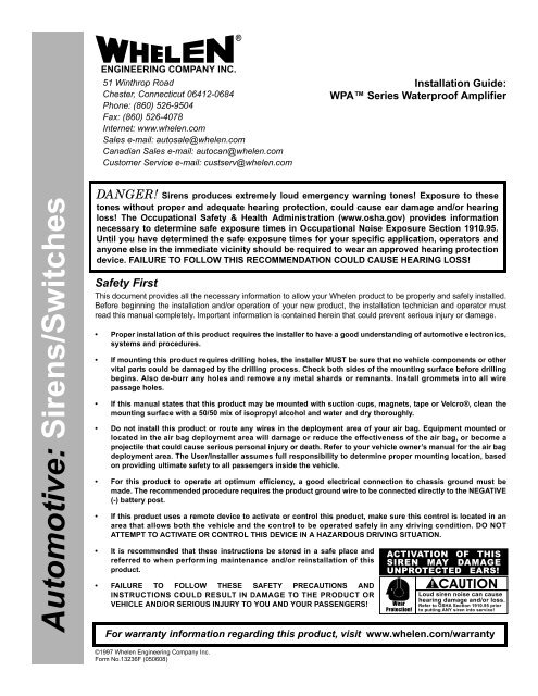
Installation Guide:<br />
<strong>WPA</strong> <strong>Series</strong> <strong>Waterproof</strong> <strong>Amplifier</strong><br />
Automotive: <strong>Siren</strong>s/Switches<br />
DANGER! <strong>Siren</strong>s produces extremely loud emergency warning tones! Exposure to these<br />
tones without proper and adequate hearing protection, could cause ear damage and/or hearing<br />
loss! The Occupational Safety & Health Administration (www.osha.gov) provides information<br />
necessary to determine safe exposure times in Occupational Noise Exposure Section 1910.95.<br />
Until you have determined the safe exposure times for your specific application, operators and<br />
anyone else in the immediate vicinity should be required to wear an approved hearing protection<br />
device. FAILURE TO FOLLOW THIS RECOMMENDATION COULD CAUSE HEARING LOSS!<br />
Safety First<br />
This document provides all the necessary information to allow your <strong>Whelen</strong> product to be properly and safely installed.<br />
Before beginning the installation and/or operation of your new product, the installation technician and operator must<br />
read this manual completely. Important information is contained herein that could prevent serious injury or damage.<br />
• Proper installation of this product requires the installer to have a good understanding of automotive electronics,<br />
systems and procedures.<br />
• If mounting this product requires drilling holes, the installer MUST be sure that no vehicle components or other<br />
vital parts could be damaged by the drilling process. Check both sides of the mounting surface before drilling<br />
begins. Also de-burr any holes and remove any metal shards or remnants. Install grommets into all wire<br />
passage holes.<br />
• If this manual states that this product may be mounted with suction cups, magnets, tape or Velcro®, clean the<br />
mounting surface with a 50/50 mix of isopropyl alcohol and water and dry thoroughly.<br />
• Do not install this product or route any wires in the deployment area of your air bag. Equipment mounted or<br />
located in the air bag deployment area will damage or reduce the effectiveness of the air bag, or become a<br />
projectile that could cause serious personal injury or death. Refer to your vehicle owner’s manual for the air bag<br />
deployment area. The User/Installer assumes full responsibility to determine proper mounting location, based<br />
on providing ultimate safety to all passengers inside the vehicle.<br />
• For this product to operate at optimum efficiency, a good electrical connection to chassis ground must be<br />
made. The recommended procedure requires the product ground wire to be connected directly to the NEGATIVE<br />
(-) battery post.<br />
• If this product uses a remote device to activate or control this product, make sure this control is located in an<br />
area that allows both the vehicle and the control to be operated safely in any driving condition. DO NOT<br />
ATTEMPT TO ACTIVATE OR CONTROL THIS DEVICE IN A HAZARDOUS DRIVING SITUATION.<br />
• It is recommended that these instructions be stored in a safe place and<br />
referred to when performing maintenance and/or reinstallation of this<br />
product.<br />
• FAILURE TO FOLLOW THESE SAFETY PRECAUTIONS AND<br />
INSTRUCTIONS COULD RESULT IN DAMAGE TO THE PRODUCT OR<br />
VEHICLE AND/OR SERIOUS INJURY TO YOU AND YOUR PASSENGERS!<br />
ACTIVATION OF THIS<br />
SIREN MAY DAMAGE<br />
UNPROTECTED EARS!<br />
Wear<br />
Protection!<br />
CAUTION<br />
Loud siren noise can cause<br />
hearing damage and/or loss.<br />
Refer to OSHA Section 1910.95 prior<br />
to putting ANY siren into service!<br />
For warranty information regarding this product, visit www.whelen.com/warranty<br />
©1997 <strong>Whelen</strong> <strong>Engineering</strong> Company Inc.<br />
Form No.<strong>13236</strong>F (050608)<br />
Page 1
INTRODUCTION...<br />
This manual outlines the procedures necessary for the<br />
installation of the <strong>WPA</strong> TM <strong>Series</strong> <strong>Waterproof</strong> <strong>Amplifier</strong>. This<br />
includes the 100 Watt models (<strong>WPA</strong>112, <strong>WPA</strong>124) and 58 Watt<br />
models (<strong>WPA</strong>512 and <strong>WPA</strong>524).<br />
Mounting the <strong>WPA</strong> <strong>Series</strong> <strong>Waterproof</strong><br />
<strong>Siren</strong> <strong>Amplifier</strong>:<br />
Caution: If the amplifier is mounted vertically, it must<br />
be oriented so that the connector end of the amplifier<br />
is facing downward!<br />
1. Locate a suitable mounting location for the <strong>WPA</strong>. Do not<br />
mount this product in any location where it may be exposed<br />
to extreme temperatures.<br />
2. Be sure that the remote amplifier fits properly and does not<br />
interfere with any vehicle components.<br />
3. Position the remote amplifier on the proposed mounting<br />
location. Using an awl or other suitable tool, scribe the<br />
mounting surface where the mounting holes are to be<br />
drilled.<br />
Caution: As mounting the <strong>WPA</strong> will require drilling, it<br />
is absolutely necessary to make sure that no other<br />
vehicle components could be damaged by the<br />
drilling process. If damage is likely, select a different<br />
mounting location.<br />
4. Carefully drill the mounting holes in the areas scribed in<br />
step 3. The diameter of these holes will be determined by<br />
the size of the mounting hardware and the thickness of the<br />
mounting surface.<br />
5. Using the supplied #10 x 3/4” sheet metal screws and #10<br />
external tooth lock washers, secure the remote amplifier to<br />
the mounting location.<br />
Wiring the <strong>WPA</strong> <strong>Series</strong> <strong>Waterproof</strong><br />
<strong>Amplifier</strong>:<br />
Connecting To Power:<br />
1. Following the factory wiring harness, extend the RED and<br />
BLACK wires to the battery.<br />
WARNING! All customer supplied wires that connect to the<br />
positive terminal of the battery must be sized to supply at<br />
least 125% of the maximum operating current and FUSED<br />
at the battery to carry that load. DO NOT USE CIRCUIT<br />
BREAKERS WITH THIS PRODUCT!<br />
2. Connect the RED wire to one end of a user supplied fuse<br />
block. Do not connect this unit to the battery yet!<br />
3. Connect the BLACK wire directly to the vehicle’s chassis<br />
ground (typically adjacent to the battery).<br />
Connecting To Your Speaker:<br />
1. Route the ORANGE and BROWN wires towards your<br />
speaker.<br />
2. Connect the ORANGE wire to the POSITIVE (+) terminal<br />
on the speaker.<br />
3. Connect the BROWN wire to the NEGATIVE (-) terminal on<br />
the speaker.<br />
Note:<br />
The two (2) BLUE wires are used to connect<br />
your two-way radio’s external speaker to the<br />
<strong>WPA</strong> for radio rebroadcast. This is an<br />
optional connection and does not effect the<br />
other operations of the <strong>WPA</strong>.<br />
Wiring The <strong>WPA</strong> <strong>Siren</strong> <strong>Amplifier</strong> Radio<br />
Rebroadcast Wires (BLUE):<br />
1. Locate the two wires that connect the external speaker to<br />
the vehicle’s two-way radio.<br />
2. Cut one of these wires and splice one of the BLUE wires<br />
into this circuit.<br />
3. Cut the remaining speaker wire and splice the remaining<br />
BLUE wire into this circuit.<br />
Note: Radio rebroadcast will NOT work with<br />
amplified remote speakers! If your remote<br />
speaker is amplified (i.e.: contains a power<br />
amp circuit in the speaker assembly), do not<br />
enable the radio rebroadcast feature.<br />
Connecting To Your Horn Relay (Optional):<br />
Note: This option can only be enabled when using<br />
customer supplied switches.<br />
1. Locate your vehicle’s horn relay. Now locate the wire that<br />
connects the vehicle horn to the horn relay output and cut<br />
this wire.<br />
2. Extend each end of the cut wire (using a minimum 16<br />
gauge wire) to a user supplied SPDT (single pole/double<br />
throw) horn transfer switch.<br />
3. Connect the wire coming from the horn relay output to the<br />
switch “wiper” as shown in Figure 1.<br />
4. Connect the wire coming from the horn to one side of the<br />
switch as shown in Figure 1.<br />
5. Connect the WHITE/GREEN wire to the other side of the<br />
switch as shown in Figure 1.<br />
Page 2
Wiring The <strong>WPA</strong> <strong>Series</strong> <strong>Waterproof</strong> <strong>Amplifier</strong> To The Controls<br />
If the <strong>WPA</strong> M series control head (optional) is not used, siren configuration and functionality are determined by user supplied switches<br />
connected to the <strong>WPA</strong> amplifier. A brief explanation of each of the function wires will serve as a guide to help determine the best<br />
configuration for your specific needs (see table 1):<br />
RED/WHITE<br />
WHITE/GREEN<br />
WHITE/BROWN<br />
WHITE/RED<br />
WHITE/BROWN +<br />
WHITE/RED<br />
WHITE/ORANGE<br />
WHITE/YELLOW<br />
WHITE/RED +<br />
WHITE/ORANGE<br />
WHITE/BROWN +<br />
WHITE/RED +<br />
WHITE/ORANGE<br />
Provides current for customer<br />
supplied switch operation (0.5 amp<br />
max).<br />
Connects to a user supplied horn<br />
transfer switch (see Figure 1). This<br />
enables the vehicle horn ring to<br />
control the siren.<br />
Activates the Wail tone.<br />
Activates the Yelp tone.<br />
Activates Piercer tone.<br />
Enables Hands-Free operation.<br />
Activates Airhorn tone.<br />
TONE CONTROL<br />
TABLE<br />
WHITE/BROWN<br />
WHITE/RED<br />
WHITE/BROWN<br />
&<br />
WHITE/RED<br />
WHITE/ORANGE<br />
WHITE/YELLOW<br />
WHITE/RED<br />
&<br />
WHITE/ORANGE<br />
WHITE/BROWN<br />
&<br />
WHITE/RED<br />
&<br />
WHITE/ORANGE<br />
+ Battery<br />
Terminal<br />
WAIL<br />
+ Battery<br />
Terminal<br />
Places <strong>WPA</strong> in Manual Mode. Applying +12VDC to these wires will activate a tone that rises in pitch to a<br />
preset level.<br />
Places <strong>WPA</strong> in Radio Mode. In this mode any signal that is received by the vehicle’s two-way radio will be<br />
simultaneously broadcast over the vehicle’s loud speaker.<br />
YELP<br />
Table 1<br />
+ Battery<br />
Terminal<br />
PIERCER<br />
+ Battery<br />
Terminal<br />
HANDS-FREE<br />
MODE<br />
+ Battery<br />
Terminal<br />
AIRHORN<br />
+ Battery<br />
Terminal<br />
MANUAL<br />
MODE<br />
+ Battery<br />
Terminal<br />
RADIO<br />
MODE<br />
Fig. 1<br />
<strong>WPA</strong> TM<br />
WATER-PROOF<br />
AMPLIFIER<br />
HORN TRANSFER SWITCH<br />
(CUSTOMER SUPPLIED)<br />
SPDT<br />
TO<br />
HORN<br />
RELAY<br />
OUTPUT<br />
SPEAKER<br />
CHASSIS<br />
GROUND<br />
+<br />
-<br />
BATTERY<br />
ORG<br />
BRN<br />
10 AMP FUSE (12V installation)<br />
7.5 AMP FUSE (24V installation)<br />
(CUSTOMER SUPPLIED)<br />
-<br />
+<br />
BLK<br />
RED<br />
+ BLU<br />
BLU<br />
-<br />
TWO-WAY<br />
RADIO SPEAKER<br />
CONNECTED IN PARALLEL<br />
WHT/GRN (Horn Ring)<br />
RED/WHT (Aux. Power)<br />
WHT/BRN (Wail Tone)<br />
WHT/RED (Yelp Tone)<br />
WHT/ORG (Hands-Free)<br />
WHT/YEL (Airhorn)<br />
WHT/VIO (Push To Talk)<br />
WHT/BLU (MIC +)<br />
WHT/BLK (MIC -)<br />
CUSTOMER SUPPLIED SWITCHES<br />
(SINGLE POLE/SINGLE THROW<br />
& MOMENTARY)<br />
VEHICLE<br />
HORN<br />
CUT<br />
HERE<br />
The installation of your <strong>WPA</strong> <strong>Series</strong> siren amplifier will be complete after the fuse block wire is<br />
connected to the POSITIVE (+) terminal of the battery. After this connection has been made,<br />
inspect the fuses at the amplifier and at the battery. If either of these fuses are blown,<br />
carefully inspect all of the circuit wires and make sure they are wired correctly. Replace the<br />
blown fuses with one of an identical amp rating as the original. If these fuses blow after<br />
installation or activation, contact <strong>Whelen</strong> <strong>Engineering</strong> Technical Support.<br />
ACTIVATION OF THIS<br />
SIREN MAY DAMAGE<br />
UNPROTECTED EARS!<br />
Wear<br />
Protection!<br />
CAUTION<br />
Loud siren noise can cause<br />
hearing damage and/or loss.<br />
Refer to OSHA Section 1910.95 prior<br />
to putting ANY siren into service!<br />
Page 3
Hands-Free <strong>Siren</strong> Activation...<br />
The <strong>WPA</strong> <strong>Series</strong> <strong>Waterproof</strong> <strong>Amplifier</strong>, when installed<br />
according to the wiring diagram above, offers the ability to<br />
activate siren tones using the vehicle’s steering wheel horn ring.<br />
After the horn transfer switch has been set to siren operation,<br />
the hands-free mode is enabled when the customer installed<br />
control switch, connected via the WHT/ORG wire, is closed.<br />
When the hands-free mode is enabled, pressing the horn ring<br />
button will start the Wail siren tone. A second press of the horn<br />
ring button will change the siren tone from Wail to Yelp. A third<br />
press will change the siren tone from Yelp to Piercer. The<br />
siren tones will continue to cycle from Wail to Yelp to Piercer<br />
with each subsequent press of the horn ring button. Two, rapid<br />
presses on the horn ring button ends hands-free siren tone<br />
generation until the horn ring button is pressed again. At that<br />
time the cycle is repeated.<br />
To exit the hands-free mode, end current siren tone, turn off the<br />
customer installed switch for the hands-free mode and return<br />
the horn transfer switch to its normal operating position. Normal<br />
vehicle horn operation is then restored.<br />
To Adjust the Radio Repeat Levels...<br />
Before using the <strong>WPA</strong> <strong>Series</strong> <strong>Waterproof</strong> <strong>Amplifier</strong>, the Radio<br />
Repeat output volume must be adjusted to satisfactory<br />
operating levels. To adjust this level, a small, flat-blade<br />
screwdriver is needed.<br />
Radio Repeat Volume<br />
Locate the Radio Repeat adjustment port (potentiometer) to the<br />
left of the 12-position input port on the remote amplifier. The<br />
potentiometer is hidden behind a 10-32 Phillips head machine<br />
screw. Once this screw is removed, set the volume level of the<br />
vehicle’s two-way radio to its normal operating volume. Place<br />
the amplifier in Radio Repeat mode. Insert the screwdriver in<br />
the Radio Repeat adjustment port and turn in a clockwise<br />
direction to increase the sound to its maximum desired volume.<br />
Return the Phillips head screw to its original position (see Fig. 2<br />
below).<br />
POTENTIOMETER (HIDDEN BEHIND<br />
A 10-32 x 5/16" MACHINE SCREW<br />
Fig. 2<br />
Manual <strong>Siren</strong> Activation (Manual Mode)...<br />
The <strong>WPA</strong> <strong>Siren</strong> <strong>Amplifier</strong>, when installed according to the wiring<br />
diagram (Figure 1), offers manual siren activation using the<br />
vehicle’s steering wheel horn ring as a momentary switch. After<br />
the horn transfer switch has been set to siren operation, the<br />
horn ring button will now activate the manual siren tone. The<br />
manual siren tone “ramps up” to a predetermined level and<br />
continues at that level until the manual switch is released. When<br />
the switch is released, the tone is immediately terminated.<br />
<strong>WPA</strong> TM SIREN SPECIFICATIONS<br />
REAR VIEW OF THE AMPLIFIER<br />
SPEC: <strong>WPA</strong>112 TM <strong>WPA</strong>124 TM <strong>WPA</strong>512 TM <strong>WPA</strong>524 TM<br />
INPUT VOLTAGE 13.5 VDC ± 20% 26.5 VDC ± 20% 13.5 VDC ± 20% 26.5 VDC ± 20%<br />
INPUT CURRENT (OFF) 0 mA 0 mA 0 mA 0 mA<br />
INPUT CURRENT (STANDBY) 10 mA (TYP.) 5 mA (TYP.) 10 mA (TYP.) 5 mA (TYP.)<br />
INPUT CURRENT (SIREN) 8 Amps (TYP.) 4 Amps (TYP.) 5 Amps (TYP.) 3 Amps (TYP.)<br />
OUTPUT VOLTAGE 34 V RMS (MAX.) 34 V RMS (MAX.) 25 V RMS (MAX.) 25 V RMS (MAX.)<br />
SPEAKER (1) 11 ohm (1) 11 ohm (1) 11 ohm (1) 11 ohm<br />
OUTPUT POWER @ 15 VDC 105 WATTS (MAX.) 105 WATTS (MAX.) 58 WATTS (MAX.) 58 WATTS (MAX.)<br />
CONROL VOLTAGE INPUT VOLTAGE INPUT VOLTAGE INPUT VOLTAGE INPUT VOLTAGE<br />
CONTROL CURRENT 125 mA (TYP.) 125 mA (TYP.) 125 mA (TYP.) 125 mA (TYP.)<br />
HORN RING VOLTAGE INPUT VOLTAGE INPUT VOLTAGE INPUT VOLTAGE INPUT VOLTAGE<br />
OR GROUND OR GROUND OR GROUND OR GROUND<br />
HORN RING CURRENT 15 mA (TYP.) 15 mA (TYP.) 15 mA (TYP.) 15 mA (TYP.)<br />
OPERATING TEMP. -30° C TO +60° C -30° C TO +60° C -30° C TO +60° C -30° C TO +60° C<br />
OPERATING HUMIDITY 95% NON-CONDENSING 95% NON-CONDENSING 95% NON-CONDENSING 95% NON-CONDENSING<br />
Page 4