Owner's Manual - Hunter Fan
Owner's Manual - Hunter Fan
Owner's Manual - Hunter Fan

Create successful ePaper yourself
Turn your PDF publications into a flip-book with our unique Google optimized e-Paper software.
For Your Records and Warranty<br />
Assistance<br />
Model Name: _____________________<br />
Catalog/Model No.: _________________<br />
Serial No.: ________________________<br />
Date Purchased: ____________________<br />
Where Purchased: _ _________________<br />
For reference also attach your receipt or a<br />
copy of your receipt to the manual.<br />
<strong>Hunter</strong> <strong>Fan</strong> Company 42761-01 • 07/09/07
Welcome<br />
READ AND SAVE THESE INSTRUCTIONS<br />
Your new <strong>Hunter</strong>® ceiling fan is an addition to your home or office that will provide comfort and<br />
performance for many years. This installation and operation manual gives you complete instructions for<br />
installing and operating your fan.<br />
We are proud of our work. We appreciate the opportunity to supply you with the best ceiling fan available<br />
anywhere in the world.<br />
Before installing your fan, for your records and warranty assistance, record information from the carton<br />
and <strong>Hunter</strong> nameplate label (located on the top of the fan motor housing).<br />
These installation instructions are for a <strong>Hunter</strong> Type “ C “ <strong>Fan</strong>.<br />
Cautions and Warnings<br />
• Read this entire manual carefully before beginning installation. Save these instructions.<br />
• Use only <strong>Hunter</strong> replacement parts.<br />
• To reduce the risk of personal injury, attach the fan directly to the support structure of the building<br />
according to these instructions, and use only the hardware supplied.<br />
• To avoid possible electrical shock, before installing your fan, disconnect the power by turning off the<br />
circuit breakers to the outlet box and associated wall switch location. If you cannot lock the circuit<br />
breakers in the off position, securely fasten a prominent warning device, such as a tag, to the service<br />
panel.<br />
• All wiring must be in accordance with national and local electrical codes and ANSI/NFPA 70. If you are<br />
unfamiliar with wiring, use a qualified electrician.<br />
• To reduce the risk of personal injury, do not bend the blade attachment system when installing,<br />
balancing, or cleaning the fan. Never insert foreign objects between rotating fan blades.<br />
• To reduce the risk of fire, electrical shock, or motor damage, do not use a solid-state speed control with<br />
this fan. Use only <strong>Hunter</strong> speed controls.<br />
Table of Contents<br />
1 • Welcome . . . . . . . . . . . . . . . . . . . . . . . . . . . 2<br />
2 • Optional Accessories . . . . . . . . . . . . . . . . . . . 3<br />
3 • Getting Ready. . . . . . . . . . . . . . . . . . . . . . . . 4<br />
4 • Pre-Installation . . . . . . . . . . . . . . . . . . . . . . . 5<br />
5 • Installing Ceiling Hardware. . . . . . . . . . . . . . . . 6<br />
6 • Hanging The <strong>Fan</strong> . . . . . . . . . . . . . . . . . . . . . 7-8<br />
7 • Wiring The <strong>Fan</strong> . . . . . . . . . . . . . . . . . . . . . . . 9<br />
8 • Installing The Canopy . . . . . . . . . . . . . . . . . . .10<br />
9 • Lubrication . . . . . . . . . . . . . . . . . . . . . . . . .11<br />
10 • <strong>Fan</strong> Blade Assembly . . . . . . . . . . . . . . . . . . .12<br />
11 • Operation And Care . . . . . . . . . . . . . . . . . . .13<br />
12 • Troubleshooting Guide . . . . . . . . . . . . . . . . .14<br />
<strong>Hunter</strong> <strong>Fan</strong> Company <br />
42761-01 • 07/09/07
Optional Accessories<br />
Understanding Mounting<br />
<strong>Hunter</strong>’s patented mounting system provides you maximum ease in installing your fan. This fan was<br />
designed to be mounted only on flat ceilings and can be used only on ceilings no less than 8 feet high.<br />
Considering Optional Accessories<br />
Consider using <strong>Hunter</strong>’s optional accessories, including a wall-mounted or remote speed control.<br />
To install and use the accessories, follow the instructions included with each product. For quiet and<br />
optimum performance of your <strong>Hunter</strong> fan, use only <strong>Hunter</strong> speed controls.<br />
Standard Mounting<br />
hangs from the ceiling by a<br />
downrod (included), recommended<br />
for ceilings 8 feet or higher<br />
<strong>Hunter</strong> <strong>Fan</strong> Company <br />
42761-01 • 07/09/07
Getting Ready<br />
To install a ceiling fan, be sure you can do the following:<br />
• Locate the ceiling joist or other suitable support in ceiling.<br />
• Drill holes for and install wood screws.<br />
• Identify and connect electrical wires.<br />
• Lift 40 pounds.<br />
If you need help installing the fan, your <strong>Hunter</strong> fan dealer can direct you to a licensed installer or<br />
electrician.<br />
Gathering the Tools<br />
You will need the following tools for installing the fan:<br />
• Adjustable wrench or pliers<br />
• Electric drill with 11/64” bit<br />
• Standard screwdriver (magnetic tip recommended)<br />
• Phillips-head screwdriver (magnetic tip recommended)<br />
• Ladder (height dependent upon installation site)<br />
• 3/8” socket wrench<br />
Checking Your <strong>Fan</strong> Parts<br />
Carefully unpack your fan to avoid damage to the fan parts. Refer to the included Parts Guide. Check<br />
for any shipping damage to the motor or fan blades. If any parts are missing or damaged, contact<br />
your <strong>Hunter</strong> dealer or call <strong>Hunter</strong> Technical Support Department at 888-830-1326.<br />
Preparing the <strong>Fan</strong> Site<br />
Before you begin installing the fan, follow all the instructions in the pullout sheet called “Preparing<br />
the <strong>Fan</strong> Site.” Proper ceiling fan location and attachment to the building structure are essential for<br />
safety, reliable operation, maximum efficiency, and energy savings.<br />
Installing Multiple <strong>Fan</strong>s?<br />
If you are installing more<br />
than one fan, keep the blade<br />
assemblies in sets, as they were<br />
shipped.<br />
<strong>Hunter</strong> <strong>Fan</strong> Company <br />
42761-01 • 07/09/07
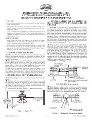
Pre-Installation<br />
Pre- Installation<br />
Select installation site: Normally this is near the center of the room, often replacing a light fixture.<br />
Make certain that ample clearance is left for the rotating fan blades. For maximum efficiency, no<br />
obstruction (walls, posts, etc.) should be within 24” of the tips of the blades (see Fig. 1).<br />
Your <strong>Hunter</strong> fan comes with the proper hardware to hang the fan from a 8 foot ceiling so the fan<br />
blades will be 12” from the ceiling and approximately 7 feet from the floor (see Fig. 1).<br />
NOTE: On vaulted ceilings, up to 45° pitch, you may want to use the <strong>Hunter</strong> Vaulted Ceiling<br />
Mounting Kit (22174). This kit can be purchased via our website or our parts and service number<br />
provided on page 14 of this manual.<br />
CAUTION<br />
! !<br />
NEVER LIFT THE MOTOR BY THE WIRES.<br />
LET MOTOR REST IN THE CARTON LINER FOR PROTECTION.<br />
12” (ref.) Minimum<br />
24” Clearance<br />
7’ From Floor<br />
Fig. 1<br />
<strong>Hunter</strong> <strong>Fan</strong> Company <br />
42761-01 • 07/09/07
Installing Ceiling Hardware<br />
! CAUTION !<br />
DO NOT USE LUBRICANT ON SCREWS<br />
1. Drill (2) 11/64” diameter holes through the outermost holes in the box 2” deep into the cross brace.<br />
These holes are for the U-bracket bolts. Install rubber bushing and pin into the u-bracket. Use a<br />
3/8” wrench to install the (2) 3 1/2” lag bolts to secure the U-bracket to the joist (see Fig. 2).<br />
Exploded View<br />
Installed View<br />
Cross<br />
Brace<br />
Rubber<br />
Bushing<br />
and Pin<br />
Ceiling<br />
Outlet<br />
Box<br />
U-Bracket<br />
Lag Bolt<br />
Fig. 2<br />
3 1/2” Lag Bolt<br />
<strong>Hunter</strong> <strong>Fan</strong> Company <br />
42761-01 • 07/09/07
Hanging The <strong>Fan</strong><br />
CAUTION<br />
! !<br />
BE SURE TO TIGHTEN THE HANGER PIPE INTO THE FAN, AND THE<br />
HANGER BRACKET ONTO THE PIPE. TIGHTEN THE 2 SET SCREWS, AS<br />
DESCRIBED IN STEP 7, TO PREVENT THE FAN FROM FALLING. YOUR FAN<br />
MAY WEIGH UP TO 50 LBS. ALL OF THE FOLLOWING STEPS MUST BE<br />
FOLLOWED IN ORDER TO ENSURE A SECURE MOUNTING.<br />
1. Feed the wires from the top of your motor through the hanger pipe (see Fig. 3).<br />
2. Back out the motor housing set screw (Do not completely remove from fan) in neck of fan motor<br />
housing and hanger bracket assembly so the hanger pipe can be screwed in.<br />
3. Screw the pipe into the fan until tight (at least 4 1/2 turns) (see Fig. 4).<br />
NOTE: Some of the pipe threads may still be visible.<br />
Wires<br />
Hanger<br />
Pipe<br />
Motor<br />
Housing<br />
Motor Housing<br />
Set Screw<br />
Fig. 3 Fig. 4<br />
<strong>Hunter</strong> <strong>Fan</strong> Company <br />
42761-01 • 07/09/07
Hanging The <strong>Fan</strong><br />
4. Back out the set screw on the hanger bracket.<br />
5. Feed the 3 wires through the hanger bracket assembly and screw the hanger bracket onto the<br />
hanger pipe until tight (at least 3 turns) (see Fig, 5).<br />
6. Use pliers to tighten both the hanger bracket assembly and the hanger pipe together.<br />
7. Tighten the set screw in the motor housing and the hanger bracket assembly (see Fig 6).<br />
Hanger<br />
Bracket<br />
Hanger<br />
Bracket<br />
Set Screw<br />
Hanger<br />
Pipe<br />
Motor Housing<br />
Set Screw<br />
Fig. 5 Fig. 6<br />
8. Be sure that the pin is centered in the rubber bushing.<br />
9. Lift the fan by the motor housing, hook the hanger bracket assembly onto the rubber bushing<br />
and pin. Make sure both ends of the pin are outside the hanger bracket assembly (see Fig 7).<br />
Rubber<br />
Bushing<br />
and Pin<br />
Hanger<br />
Bracket<br />
Assembly<br />
Fig. 7<br />
<strong>Hunter</strong> <strong>Fan</strong> Company <br />
42761-01 • 07/09/07
Wiring the <strong>Fan</strong><br />
CAUTION<br />
! !<br />
BE CERTAIN THAT THE ELECTRICITY IS TURNED OFF AT THE<br />
MAIN PANEL BEFORE STARTING THIS SECTION.<br />
NOTE: All wiring must be in accordance with<br />
national and local electrical codes and ANSI/<br />
NFPA 70-1999. If you are unfamiliar with<br />
wiring, use a qualified electrician.<br />
Wall switches are not included. Select an<br />
acceptable general-use switch in accordance with<br />
national and local electrical codes.<br />
1. Before attempting installation, make sure the<br />
power is still off.<br />
2. To connect the wires, hold the bare metal<br />
leads together and place a wire connector over<br />
them, then twist clockwise until tight. For all<br />
these connections use the wire nuts provided.<br />
3. Connect the bare or green ground wire<br />
(grounded) from the ceiling to the side of the<br />
hanger bracket assembly.<br />
4. Connect the white wire (ungrounded) from the<br />
ceiling to the white wire (ungrounded) from<br />
the fan.<br />
5. Connect the remaining wires as follows:<br />
Dual Switch Wiring (see Fig. 8):<br />
• The black wire (ungrounded) from the ceiling<br />
to the black wire (ungrounded) from the fan.<br />
• The black/white wire (ungrounded) from the<br />
fan to the wire (ungrounded) from the wall<br />
switch.<br />
Single Switch Wiring (see Fig. 9):<br />
• The black wire (ungrounded) from the ceiling<br />
to the black (ungrounded) and the black/white<br />
wire (ungrounded) from the fan.<br />
CAUTION<br />
! !<br />
NO BARE WIRES OR WIRE STRANDS SHOULD<br />
BE VISIBLE AFTER MAKING CONNECTIONS.<br />
6. Turn the splices upward and push them<br />
carefully into the outlet box.<br />
7. Spread the wires apart, with the grounded<br />
wires on one side of the outlet box and the<br />
ungrounded wires on the other side of the<br />
outlet box.<br />
Fig. 8<br />
Fig. 9<br />
Wire Connector<br />
<strong>Hunter</strong> <strong>Fan</strong> Company <br />
42761-01 • 07/09/07
Installing The Canopy<br />
NOTE: Your canopy come pre-assembled. Uninstall the canopy screws and separate the two half of<br />
the canopy before continuing to step 1.<br />
1. Assemble canopy halves around pipe, and loosely install the canopy assembly screws.<br />
2. Slide canopy up close to ceiling.<br />
3. Tighten the canopy assembly screws (see Fig. 10).<br />
4. Tighten the canopy set screw (see Fig. 10).<br />
Canopy<br />
Canopy Assembly<br />
Screw (2)<br />
Canopy Set Screw<br />
Fig. 10<br />
<strong>Hunter</strong> <strong>Fan</strong> Company 10<br />
42761-01 • 07/09/07
Lubrication<br />
CAUTION<br />
! !<br />
DO NOT TURN FAN ON UNTIL LUBRICATION HAS BEEN ADDED. TO OPERATE THE FAN<br />
WITHOUT OIL OR WITH LOW OIL WILL VOID YOUR WARRANTY.<br />
Adding Oil<br />
1. Your fan has been shipped without oil in the motor.<br />
2. A 1-ounce tube of high grade SAE 10 non-detergent oil is packaged in the sack parts.<br />
3. All of the oil in the tube must be put into the fan.<br />
4. Cut the tip off the end of the tube and place the tube into the oil hole (see. Fig. 11).<br />
NOTE: To avoid overflowing during filling, allow oil to gravity flow about one minute to fill the oil<br />
reservoir. (It may be necessary to puncture the tube to allow air in.)<br />
Checking Oil<br />
1. Check oil level immediately after filling the reservoir and every 1 to 5 years thereafter.<br />
2. To check oil, bend an ordinary pipe cleaner into 1/2” long hook and dip it into the oil reservoir.<br />
3. If the oil touches the end of the pipe cleaner, the fan has ample oil. If it does not touch, add SAE 10<br />
non-detergent oil slowly until it touches the pipe cleaner. (see. Fig. 12).<br />
Oil Tube<br />
Oil Hole<br />
Fig. 11<br />
Fig. 12<br />
Pipe<br />
Cleaner<br />
Oil<br />
Reservoir<br />
Your Original <strong>Hunter</strong>’s Unique Lubricating System<br />
The bearings are submerged in a bath of oil. The oil moves up a spiral groove in the shaft, lubricating<br />
all bearing surfaces as the fan operates. The Lubrication System does not normally “use up” or require<br />
the addition of extra oil once the oil reservoir has been filled to the correct level. This unique<br />
lubrication system is one reason your Original <strong>Hunter</strong> Ceiling <strong>Fan</strong> will last a lifetime. It is highly<br />
unlikely that you will ever need to add oil to you Original fan once it is installed. Should you move<br />
your fan to another location, it is a good idea to check the oil reservoir. <strong>Hunter</strong> has developed an<br />
accessory ‘Original Relocation Kit’ that includes all mounting hardware and a fresh tube of oil for this<br />
reason. The model number is 22360.<br />
<strong>Hunter</strong> <strong>Fan</strong> Company 11<br />
42761-01 • 07/09/07
<strong>Fan</strong> Blade Assembly<br />
CAUTION<br />
! !<br />
TO REDUCE THE RISK OF PERSONAL INJURY, DO NOT BEND THE BLADE<br />
BRACKETS WHEN INSTALLING THE BRACKETS, BALANCING THE<br />
BLADES, OR CLEANING THE FAN. DO NOT INSERT FOREIGN OBJECTS<br />
IN BETWEEN ROTATING FAN BLADES.<br />
<strong>Fan</strong> Blade Assembly<br />
1. Your fan may include blade grommets. If yout fan has grommets, insert them by hand into the<br />
holes on the blades (see Fig. 13).<br />
2. Attach each blade to a blade iron using three blade assembly screws. If you used grommets, the<br />
blades may appear slightly loose after the screws are tightened. This is normal (see Fig. 14).<br />
Blade<br />
Grommet<br />
Blade Assembly<br />
Screw<br />
Fig. 13<br />
Fig. 14<br />
Installation Of <strong>Fan</strong> Blade Assembly<br />
1. Loosen the blade assembly screw, but do not remove.<br />
2. Align the blade blase assembly screw with the Adapt Air blade shaft counter sink (see Fig. 15).<br />
3. Slide the blade assembly onto the Adapt Air blade shaft. (see Fig. 16).<br />
4. Before tightening the blade assembly screw, slightly turn blade assembly while hand tightening the<br />
set screw.<br />
5. Tighten the blade assemble screw with pliers or adjustable wrench.<br />
Blade<br />
Counter Sink<br />
Adapt Air<br />
Blade Shaft<br />
Blade Assembly<br />
Screw<br />
Fig. 15<br />
Fig. 16<br />
<strong>Hunter</strong> <strong>Fan</strong> Company 12<br />
42761-01 • 07/09/07
Operation And Care<br />
1. The fan pull chain controls power to the fan. The pull chain has four settings in sequence: High,<br />
Medium, Low and Off.<br />
• Pull the chain slowly to change settings.<br />
• Release slowly to prevent the chain from recoiling into the blades.<br />
• The chain uses a breakaway connector that separates if the chain is jerked. If this happens, simply<br />
reinsert the chain into the connector (see Fig. 17).<br />
2. For cleaning finishes, use a soft brush or lint-free cloth to prevent scratching. A vacuum cleaner<br />
brush nozzle can remove heavier dust. Remove surface smudges or accumulated dirt and dust<br />
using a mild detergent and a slightly dampened cloth. You may use an artistic agent, but never<br />
abrasive cleaning agents as they will damage the finish.<br />
3. Clean wood finish blades with a furniture polishing cloth. Occasionally, apply a light coat of<br />
furniture polish for added protection and beauty.<br />
To Reverse The Flow Of Air.<br />
1. Move the directional lever all the way to the left side for down draft (see Fig. 18).<br />
2. Move the directional lever all the way to the right side for up draft (see Fig. 18).<br />
DOWN<br />
UP<br />
Pull Chain<br />
Directional<br />
Lever<br />
Fig. 18<br />
Breakaway<br />
Connector<br />
Fig. 17<br />
<strong>Hunter</strong> <strong>Fan</strong> Company 13<br />
42761-01 • 07/09/07
Troubleshooting Guide<br />
Problem: Nothing happens; fan does not move.<br />
1. Turn power on, replace fuse, or reset breaker.<br />
2. Check all connections according to the wiring the fan section.<br />
3. Pull the pull chain to ensure it is on.<br />
Problem: Noisy operation.<br />
1. Tighten the blade assembly screws until snug.<br />
2. Check to see if the blade is cracked. If so, replace all the blades.<br />
Problem: Excessive wobbling.<br />
1. If your fan wobbles when operating, use the enclosed balancing kit and instructions to balance the<br />
fan.<br />
If you need parts or service assistance, please call<br />
888‐830‐1326 or visit us at our WEB site at<br />
http://www.hunterfan.com.<br />
<strong>Hunter</strong> <strong>Fan</strong> Company<br />
2500 Frisco Avenue<br />
Memphis, Tennessee 38114<br />
<strong>Hunter</strong> <strong>Fan</strong> Company 14<br />
42761-01 • 07/09/07
Notes<br />
<strong>Hunter</strong> <strong>Fan</strong> Company 15<br />
42761-01 • 07/09/07
©2007 HUNTER FAN CO.<br />
®<br />
HUNTER FAN COMPANY<br />
2 5 0 0 F R I S C O A V E N U E<br />
M E M P H I S , T N 3 8 1 1 4