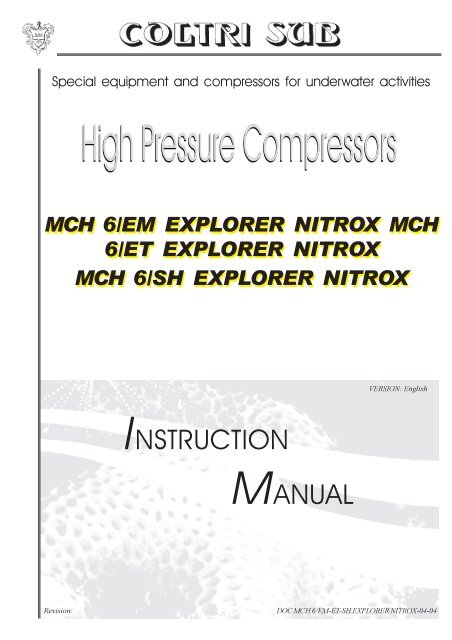
MCH 6 EM Explorer Nitrox - Submarine Manufacturing and Products ...
MCH 6 EM Explorer Nitrox - Submarine Manufacturing and Products ...
MCH 6 EM Explorer Nitrox - Submarine Manufacturing and Products ...

You also want an ePaper? Increase the reach of your titles
YUMPU automatically turns print PDFs into web optimized ePapers that Google loves.
Special equipment <strong>and</strong> compressors for underwater activities<br />
<strong>MCH</strong> 6/<strong>EM</strong> EXPLORER NITROX <strong>MCH</strong><br />
6/ET EXPLORER NITROX<br />
<strong>MCH</strong> 6/SH EXPLORER NITROX<br />
VERSION: English<br />
INSTRUCTION<br />
MANUAL<br />
Revision:<br />
DOC <strong>MCH</strong> 6/<strong>EM</strong>-ET-SH EXPLORER NITROX-04-04
USE IN BRIEF<br />
Use in brief ..................................................................................................................................... 7<br />
1<br />
GUARANTEE AND ASSISTANCE<br />
1.1 Garantee .............................................................................................................................. 9<br />
1.2 Assistance........................................................................................................................... 9<br />
2<br />
TECHNICAL DESCRIPTION<br />
2.1 Operating principle ............................................................................................................... 12<br />
2.2 Description of the pump unit .................................................................................................13<br />
2.2.1 Monobloc unit .............................................................................................................14<br />
2.2.2 Head unit .................................................................................................................... 16<br />
2.2.3 Safety valves ............................................................................................................... 16<br />
2.2.4 Lubrication unit ............................................................................................................ 17<br />
2.2.5 Pressure maintenance valve ........................................................................................ 17<br />
2.2.6 Cooling pipes .............................................................................................................. 17<br />
2.2.7 Filters.......................................................................................................................... 18<br />
2.2.8 Frame <strong>and</strong> sound-proofed casing................................................................................. 19<br />
2.3 Machine control ................................................................................................................... 19<br />
3 TECHNICAL CHARACTERISTICS<br />
3.1 Technical characteristics of the pump unit ............................................................................ 20<br />
3.1.1 Technical characteristics “<strong>MCH</strong>6” ................................................................................ 21<br />
3.1.2 Sizes <strong>and</strong> weights ....................................................................................................... 22<br />
3.2 Noise ................................................................................................................................... 23<br />
4<br />
PRECAUTIONS FOR USE AND MAINTENANCE<br />
4.1 Machine area diagrams ........................................................................................................ 25<br />
4.1.1 Safety devices ............................................................................................................. 26<br />
4.1.2 Residual risk areas ..................................................................................................... 28<br />
2<br />
Index
UNPACKING AND HANDLING THE MACHINE<br />
5<br />
5.1 Unpacking the machine........................................................................................................ 29<br />
5.2 Pack contents...................................................................................................................... 29<br />
5.3 H<strong>and</strong>ling the machine........................................................................................................... 30<br />
INSTALLATION<br />
6<br />
6.1 Positioning ........................................................................................................................... 31<br />
6.2 Connections ......................................................................................................................... 32<br />
6.2.1 Connecting the air intake extension............................................................................. 32<br />
6.2.2 Connecting the refill hoses .......................................................................................... 35<br />
6.2.3 Electrical connection for models <strong>MCH</strong> 6/<strong>EM</strong> <strong>and</strong> <strong>MCH</strong> 6/ET........................................ 35<br />
CONTROL PANEL<br />
7<br />
7.1 Control panel ....................................................................................................................... 37<br />
7.1.1 Wall-mounted control panel for models with electric power supply (optional) ...............38<br />
7.1.2 Controls on board the internal combustion engines ..................................................... 39<br />
7.2 Indication <strong>and</strong> control devices .............................................................................................. 40<br />
START AND STOP<br />
8<br />
8.1 Filling the machine ............................................................................................................... 41<br />
8.2 Checks ................................................................................................................................ 43<br />
8.2.1 Models with electric power supply ............................................................................... 43<br />
8.2.2 Models with petrol supply ............................................................................................ 45<br />
8.2.3 Calibrate analyzer ....................................................................................................... 49<br />
8.2.4 Stop ........................................................................................................................... 50<br />
USE<br />
9<br />
9.1 Preliminary operations ......................................................................................................... 53<br />
9.2 Refilling the cylinders ........................................................................................................... 55<br />
Index<br />
3
10<br />
PUTTING THE MACHINE OUT OF OPERATION<br />
AND DISMANTLING THE MACHIN<br />
10.1 Instructions for prolonged machine st<strong>and</strong>stills ...................................................................... 58<br />
10.2 Disposal of waste products ..................................................................................................61<br />
10.3 Dismantling the machine ...................................................................................................... 61<br />
11<br />
MAINTENANCE<br />
11.1 General notes ...................................................................................................................... 64<br />
11.2 Preventive maintenance ........................................................................................................ 64<br />
11.3 Changing the lubricant oil ..................................................................................................... 65<br />
11.4 Transmission belt ................................................................................................................. 66<br />
11.4.1 Checking the transmission belt.................................................................................. 66<br />
11.4.2 Disassembling the belt to be replaced ....................................................................... 67<br />
11.5 Air intake filter ...................................................................................................................... 68<br />
11.6 Active carbon filter <strong>and</strong> molecular sieve ................................................................................ 69<br />
11.7 Refill hose ............................................................................................................................ 70<br />
11.8 Intake <strong>and</strong> discharge valves .................................................................................................. 71<br />
11.9 Condensate discharge ......................................................................................................... 71<br />
11.10 Cylinders.............................................................................................................................. 71<br />
11.11 Internal combustion engines................................................................................................. 71<br />
11.11.1 Maintenance programme .......................................................................................... 72<br />
11.11.2 Oil change ............................................................................................................... 72<br />
11.11.3 Air filter .................................................................................................................... 73<br />
11.11.4 Sediment sump........................................................................................................ 74<br />
11.11.5 Spark plugs .............................................................................................................. 75<br />
11.11.6Minimum carburettor regulation ................................................................................ 77<br />
11.11.7Fuel filter ................................................................................................................... 77<br />
11.12 Check of safety devices ....................................................................................................... 78<br />
11.12.1 Check of the safety valve ......................................................................................... 79<br />
11.13 Maintenance operations ....................................................................................................... 79<br />
12<br />
TROUBLESHOOTING<br />
12.1 List of faults ......................................................................................................................... 81<br />
4<br />
Index
REGISTERS<br />
13<br />
13.1 Machine log book ................................................................................................................. 83<br />
MACHINE DIAGRAMS<br />
14<br />
14.1 NITROX compression diagram .............................................................................................. 84<br />
14.2 Compression diagram - only air ............................................................................................ 85<br />
14.2 Electricals diagrams ............................................................................................................ 63<br />
SPARE PARTS<br />
15<br />
15.1 Exploded view of the machine parts .................................................................................... 87<br />
Pumping unit ...................................................................................................................... 88<br />
<strong>MCH</strong> 6/<strong>EM</strong> EXPLORER NITROX <strong>and</strong> <strong>MCH</strong> 6/ET EXPLORER NITROX cooling plant frame ............ 90<br />
<strong>MCH</strong> 6/SH EXPLORER NITROX cooling plant frame ........................................................... 92<br />
Active carbon filter <strong>and</strong> condensate separator..................................................................... 94<br />
ANNEXES - MINI O2DII<br />
16<br />
16.1 Introduction ......................................................................................................................... 96<br />
16.2 Controls .............................................................................................................................. 97<br />
16.3 Air calibration ...................................................................................................................... 97<br />
16.4 Operation ............................................................................................................................ 98<br />
16.5 Accessories ........................................................................................................................ 98<br />
16.6 Troubleshooting ................................................................................................................... 99<br />
16.7 Maintenance ....................................................................................................................... 99<br />
16.8 Care of the Mini O2DII ....................................................................................................... 100<br />
16.9 Safety information for the Mini O2DII ................................................................................. 100<br />
16.10 Informaton on h<strong>and</strong>ling of the sensor ................................................................................. 101<br />
16.11 Details .............................................................................................................................. 101<br />
Index<br />
5
To make the manual easier to read, the following terms have been adopted:<br />
DANGER<br />
The term DANGER is used when failure to comply with the regulations or tampering with the<br />
parts could lead to serious injury or even death.<br />
CAUTION<br />
The term WARNING is used when failure to comply with the instructions could cause damage to the<br />
machine <strong>and</strong> other parts associated with the same or to the surrounding area.<br />
LABEL APPLIED TO THE COMPRESSORS<br />
To protect exposed persons or objects, a special booklet entitled “SAFETY REGULATIONS” is supplied<br />
with the machine <strong>and</strong> must be considered an integral part of the Compressor Instruction Manual.<br />
Editor’s note:this manual refers specifically to the “<strong>MCH</strong> 6 EXPLORER NITROX” series of refill stations<br />
which, as later explained, may be supplied in various arrangements although they all<br />
work on the same operating principle.<br />
For this reason, the illustrations given in the Instruction Manual should be considered<br />
only as indications insofar as they refer to just one version of refill station in the<br />
“<strong>MCH</strong> 6 EXPLORER NITROX” series.<br />
This manual is the property of AEROTECNICA COLTRI S.r.l. <strong>and</strong> any copying of the same, even partial, is<br />
prohibited.<br />
6<br />
Introduction
USE IN BRIEF<br />
The following information must be referred to <strong>and</strong> applied only when this manual <strong>and</strong> the<br />
“Safety regulations” manual have been read <strong>and</strong> their contents have been understood <strong>and</strong><br />
assimilated.<br />
VERSION WITH ELECTRIC ENGINE<br />
(<strong>MCH</strong> 6/<strong>EM</strong> EXPLORER NITROX <strong>and</strong> <strong>MCH</strong> 6/ET EXPLORER NITROX)<br />
- Check whether or not the area where the machine is installed has suitable ventilation<br />
(see chapter 6.1).<br />
- If the machine is installed in a place without the required characteristics above, connect the air<br />
intake extension (see chapter 6.2.1).<br />
- Connect the refill hoses to the machine (see chapter 6.2.2).<br />
- Connect the switchboard to the mains power supply (see chapter 6.2.3).<br />
- Check the level of the lubricating oil in the pump unit (see chapter 8.2). If the level is too low, turn off<br />
the machine <strong>and</strong> add or change the oil (see chapter 8.1).<br />
- Turn on the machine using the main switch (see chapter 7.1).<br />
- Check the direction of rotation of the motor. If the direction of rotation does not coincide with the one<br />
shown on the belt guard, turn off the machine <strong>and</strong> invert the two phases on the main power supply<br />
(see chapter 7.2).<br />
- Check the operation of the safety valve (see chapter 9.1).<br />
- Check for wear on the cylinders to be filled (see chapter 9.1).<br />
- Fit the hose attachment on the cylinder <strong>and</strong> check that the taps on the hose are open<br />
(see chapter 9.2).<br />
- Turn on the cylinder tap <strong>and</strong> start up the compressor (see chapter 9.2).<br />
- When the filling operation has been completed, the compressor is stopped automatically by the<br />
pressure switch, turn off the cylinder <strong>and</strong> the hose taps.<br />
- Press the pressure bleed button <strong>and</strong> disconnect the cylinder attachment (see chapter 9.2).<br />
Use in brief<br />
7
USE IN BRIEF<br />
The following information must be referred to <strong>and</strong> applied only when this manual <strong>and</strong> the<br />
“Safety regulations” manual have been read <strong>and</strong> their contents have been understood <strong>and</strong><br />
assimilated.<br />
VERSION WITH PETROL ENGINE (<strong>MCH</strong> 6/SH EXPLORER NITROX )<br />
- Check whether or not the area where the machine is installed has suitable ventilation<br />
(see chapter 6.1).<br />
- If the machine is installed in a place without the required characteristics above, connect the air<br />
intake extension (see chapter 6.2.1).<br />
- Connect the refill hoses to the machine (see chapter 6.2.2).<br />
- Check the level of the lubricating oil in the pump unit (see chapter 8.2). If the level is too low, turn off<br />
the machine <strong>and</strong> add or change the oil (see chapter 8.1).<br />
- Check the oil level of the internal combustion engine using the dipstick provided (see chapter 11.11.2).<br />
- Add fuel to the tank (unleaded petrol of the recommended type).<br />
- Check the operation of the safety valve (see chapter 9.1).<br />
- Check for wear on the cylinders to be filled (see chapter 9.1).<br />
- Fit the hose attachment on the cylinder <strong>and</strong> check that the taps on the hose are open<br />
(see chapter 9.2).<br />
- Turn on the cylinder tap <strong>and</strong> start up the compressor (see chapter 9.2).<br />
- When the filling operation has been completed, the compressor is stopped automatically by the<br />
pressure switch, turn off the cylinder <strong>and</strong> the hose taps.<br />
- Press the pressure bleed button <strong>and</strong> disconnect the cylinder attachment (see chapter 9.2).<br />
- Move the fuel lever to the “open” position (in an anti-clockwise direction).<br />
- Move the air lever to the “closed” position (in a clockwise direction).<br />
- Turn the accelerator lever slightly in an anti-clockwise direction.<br />
- Move the engine start switch to the “ON” position.<br />
- Pull the starter cord until a certain resistance is felt, then pull hard.<br />
STOPPING THE ENGINE<br />
In an emergency, simply move the engine switch to the “OFF” position.<br />
To stop the engine under normal circumstances:<br />
- turn the accelerator lever in an anti-clockwise direction as far as it will go;<br />
- move the engine switch to “OFF”;<br />
- move the fuel lever to “OFF” (in a clockwise direction).<br />
8<br />
Use in brief
GUARANTEE AND ASSISTANCE<br />
1<br />
Guarantee<br />
1.1<br />
AEROTECNICA COLTRI S.r.l. guarantees its compressors against any design or manufacturing<br />
defect or fault <strong>and</strong> against any fault in the materials for a period of 24 months from the delivery of the<br />
machine. The customer must inform AEROTECNICA COLTRI S.r.l. in writing of any fault <strong>and</strong>/or defect<br />
that may be found within eight days from its discovery by means of a registered letter with advice of<br />
receipt or telegramme, otherwise the guarantee will become null <strong>and</strong> void.<br />
The guarantee is only valid against faults or defects that may arise with the compressor used under<br />
proper operating conditions according to the instructions given in this manual <strong>and</strong> with the maintenance<br />
carried out at the intervals as provided for.<br />
The guarantee expressly excludes any faults arising as a result of improper use of the machine,<br />
of atmospheric agents <strong>and</strong> of damage due to transport; the guarantee does not cover the<br />
expendable materials <strong>and</strong> materials required for the periodic maintenance which are at the<br />
customer’s entire expense. The guarantee will, in any case, become automatically null <strong>and</strong> void<br />
if the compressor is tampered with or if it has been serviced by technicians who are not authorized<br />
to do so by AEROTECNICA COLTRI S.r.l.<br />
Any compressor that is acknowledged to be faulty due to defects in the design, manufacturing or<br />
materials used, will be repaired or replaced free of charge by AEROTECNICA COLTRI S.r.l. at its<br />
factory in San Martino della Battaglia (BRESCIA). The customer will be responsible for the costs of<br />
transport <strong>and</strong> carriage as well as for any spare parts <strong>and</strong> expendable materials.<br />
If it should be necessary for service to be carried out under the guarantee at the customer’s premises,<br />
the latter will be responsible for the travel <strong>and</strong> transfer costs for the staff sent out by<br />
AEROTECNICA COLTRI S.r.l.<br />
Taking delivery of the machine <strong>and</strong>/or of any faulty components or the transfers for the inspection of<br />
faults <strong>and</strong>/or defects as notified by the customer, will not, however, denote any implicit acknowledgement<br />
regarding the effectiveness of the guarantee.<br />
Repairs <strong>and</strong>/or replacements made by AEROTECNICA COLTRI S.r.l. during the guarantee period<br />
will not extend the duration of the same.<br />
Acknowledgment of the guarantee does not itself imply any liability for compensation on the part of<br />
AEROTECNICA COLTRI S.r.l.<br />
AEROTECNICA COLTRI S.r.l. does not assume any responsibility for injury to persons or damage to<br />
property or for any other direct or indirect damage (loss of production or missed profit, etc.) that may<br />
be attributable to faults or defects of the compressor, except for those cases in which a serious fault<br />
can be attributed to the company.<br />
Assistance<br />
1.2<br />
The AEROTECNICA COLTRI S.r.l. technicians are available for any kind of routine or additional<br />
maintenance work.<br />
The request for technical assistance must be sent to AEROTECNICA COLTRI S.r.l. at the following<br />
address:<br />
AEROTECNICA COLTRI S.r.l.<br />
Via Colli Storici, 177<br />
25010 San Martino della Battaglia (BRESCIA)<br />
Fax: 030 9910283<br />
e-mail: coltrisub@coltrisub.it<br />
Guarantee <strong>and</strong> assistance<br />
9
2<br />
TECHNICAL DESCRIPTION<br />
This chapter provides a technological description of the machine <strong>and</strong> its main components.<br />
2.1 Operating principle ..........................................................................................................12<br />
2.2 Description of the pump unit .......................................................................................... 13<br />
2.2.1 Monobloc unit .......................................................................................................... 14<br />
2.2.2 Head unit .................................................................................................................. 16<br />
2.2.3 Safety valves ........................................................................................................... 16<br />
2.2.4 Lubrication unit ....................................................................................................... 17<br />
2.2.5 Pressure maintenance valve .................................................................................. 17<br />
2.2.6 Cooling pipes .......................................................................................................... 17<br />
2.2.7 Filters ....................................................................................................................... 18<br />
2.2.8 Frame <strong>and</strong> sound-proofed casing.......................................................................... 19<br />
2.3 Machine control ................................................................................................................ 19<br />
10<br />
Technical description
The “<strong>MCH</strong> 6 EXPLORER NITROX” series of compressors can be supplied in versions that run on<br />
electric single or three-phase inputs or petrol fuel:<br />
- <strong>MCH</strong> 6/<strong>EM</strong> EXPLORER NITROX (Fig. 1)<br />
Electric single phase;<br />
(see specific manual for electric motor model).<br />
1<br />
- <strong>MCH</strong> 6/ET EXPLORER NITROX (Fig. 2) Electric<br />
three-phase;<br />
(see specific manual for electric motor model).<br />
2<br />
- <strong>MCH</strong> 6/SH EXPLORER NITROX (Fig. 3) Petrol<br />
(HONDA engine);<br />
(see specific manual for petrol motor model).<br />
3<br />
Technical description<br />
11
2.1 Operating principle<br />
CAUTION<br />
THE FILLING STATION PRODUCES RESPIRABLE AIR/NITROX.<br />
This system supplies to output percentages nitrox in oxygen of 24% to 40% for volume.<br />
This system supplies a breathable gas stream consisting of an elevated oxygen content relative to<br />
normal atmospheric content of approximately 21% O 2<br />
by volume. This technique employs gas separation<br />
technology utilizing a permeable membrane to separate certain gas molecules from other gas molecules<br />
allowing a controlled flow of output gasses of differing oxygen concentrations.<br />
This system produces DNAx <strong>Nitrox</strong> in oxygen concentrations of 24% to 40% at maximum pressures of<br />
3200 - 3700 PSI. A supply gas, in this case, “Grade-E” air, will be required. This supply gas is fed at low<br />
pressure (145-185 PSI) to the input port of the membrane. The gas stream is fed through a thermostatcontrolled<br />
heater. As the gas moves through this assembly, its temperature is raised to<br />
35° (110 degrees F). The purpose of this heater is to even out the variations in gas temperature <strong>and</strong><br />
produce a more linear performance curve. Once through the heater, the input gas is allowed to pass<br />
through the membrane. As the gas passes through the membrane, the gas volume applies pressure<br />
against the inside walls of the permeable fibers resulting in the migration across the wall of varying<br />
levels of the different constituents of air. Gas volumes of desired O 2<br />
concentrations are achieved in this<br />
manner. In this stage the normal oxygen content of the “Grade-E” air second the norms UNI EN 132,<br />
CGA-E <strong>and</strong> DIN 3188 (20.9%) is raised to output percentages upwards of 25% to 40%.<br />
A needle valve in the outlet stream of the waste gas (nitrogen) controls the relative O 2<br />
concentrations<br />
while input pressure regulation allows control of the output volume of the membrane. This outlet volume<br />
control is required to balance the input requirements of the high-pressure compressor. As the gas<br />
volume of desired oxygen concentration is produced it is contained <strong>and</strong> directed to the inlet port of the<br />
high-pressure compressor. An overpressure checkvalve is installed in the inlet fitting of the high-pressure<br />
compressor to protect the compressor from over pressurization of the first stage. Negative pressure<br />
protection is accomplished in the same manner by installing an under-pressure checkvalve in the ambient<br />
air intake side of the membrane output fitting.<br />
As the gas volume is subsequently compressed, it is alternately cooled <strong>and</strong> raised in pressure again<br />
until it reaches its final design output pressure. Final filtration <strong>and</strong> purification is accomplished at final<br />
compressor discharge.<br />
Product gas “DNAx” nitrox is available at desired oxygen concentrations (up to 40% O 2<br />
by volume) at<br />
maximum pressures of 3200 - 3700 PSI, for filling <strong>Nitrox</strong> Storage Bottles or SCUBA cylinders.<br />
Typical Specification for Air :<br />
O 2<br />
Percentage: ................................. 20-22 %<br />
CO 2<br />
: ................................................. 1000 PPM<br />
CO: .................................................. 10 PPM<br />
Hydrocarbons: ................................. 25 PPM<br />
Water: .............................................. 67 PPM<br />
Dew Point: ....................................... - 50° F<br />
Oil & Particles: ................................. 5 mg/m 3<br />
Odor: ............................................... Nothing<br />
12<br />
Technical description
Description of the pump unit 2.2<br />
The pumping unit has the task of producing compressed air at high pressure (200-300 bar) <strong>and</strong><br />
purifying it by means of the decantation <strong>and</strong> filtering systems until it reaches a level of purity equal to<br />
or higher than the limits set by the st<strong>and</strong>ards DIN 3188 - UNI EN 132 - CGA/E, or to increase the<br />
pressure of the gas inhaled (only inert - non-explosive gases).<br />
This unit consists of the following components (Fig. 4-5):<br />
Table 1<br />
N° Description N° Description<br />
1 Intake filter 11 Filter<br />
2 1 st stage head 13 Monobloc<br />
3 2 nd stage head 14 Filter-holding bracket<br />
4 3 rd stage head 15 Fan<br />
5 1 st stage head cover 16 Oil cap<br />
6 2 nd stage cylinder 17 Final condensate separator<br />
7 3 rd stage guiding cylinder 18 Condensate separator between stages<br />
8 Separator-holding bracket 19 Condensate discharge connection<br />
9 1 st -2 nd stage cooling pipe 21 Pipe-fastening bracket<br />
10 Final cooling pipe<br />
4 5<br />
Technical description<br />
13
2.2.1 Monobloc unit<br />
The gooseneck, the pistons <strong>and</strong> the cylinders<br />
also form a part of this unit.<br />
The monobloc (Fig. 6) is made of aluminium<br />
alloy, the two flanges with the ball <strong>and</strong> roller<br />
bearings that support the gooseneck are oiltight<br />
with the monobloc due to the O-Rings<br />
fitted.<br />
6<br />
The gooseneck <strong>and</strong> the connecting<br />
rods only turn on roller or ball<br />
bearings (Fig. 7).<br />
The three connecting rods are fitted<br />
on the gooseneck with a single<br />
crank angle.<br />
7<br />
The 1 st <strong>and</strong> 2 nd stage cylinder are made of cast<br />
iron (Fig. 8) <strong>and</strong> have traditional multiple<br />
compression rings.<br />
8<br />
14<br />
Technical description
The 3 rd stage is made of special steel with three<br />
sealing rings made of carbo graphite (Fig. 9).<br />
9<br />
The 4 th stage piston (Fig.10) is made with<br />
deaustinised steel, without piston rings coupled<br />
with the corresponding cylinder through a lapping<br />
process.<br />
10<br />
Technical description<br />
15
2.2.2<br />
Head unit (Fig. 11)<br />
The head unit includes the discharge <strong>and</strong> intake<br />
valves.<br />
The head of the 1 st stage is of a lamellar type <strong>and</strong><br />
includes both the intake <strong>and</strong> the discharge.<br />
The intake <strong>and</strong> discharge valves are located<br />
directly in their threaded seats of the heads of the<br />
2 nd <strong>and</strong> 3 rd stages.<br />
The intake valves can be removed using the<br />
special pin wrench (cod. SC000480), having first<br />
removed the heads.<br />
The discharge valves can be removed from the<br />
outside.<br />
See Chapter 11, “Maintenance”.<br />
11<br />
2.2.3<br />
Safety valves<br />
The purpose of the safety valves (Fig. 12) is to<br />
protect the machine (<strong>and</strong> the cylinders) from<br />
overpressure.<br />
The valve is pre-calibrated in the workshop at the<br />
pressure of 225 bar (3400 PSI) or 300 bar (4500<br />
PSI).<br />
CAUTION<br />
Under no circumstances may these valves be<br />
altered to increase the calibrated pressure.<br />
If these valves should come into operation, check<br />
the cause that has led to the maximum pressure<br />
<strong>and</strong> take steps according to the instructions given<br />
in paragraph 12.1.<br />
Any tampering with the safety valves causes<br />
serious damage <strong>and</strong> an immediate cancellation<br />
of the guarantee.<br />
12<br />
16<br />
Technical description
Lubricating unit<br />
2.2.4<br />
Lubrication is carried out by means of a tang<br />
screwed into the end part of the connecting rods<br />
of the 2 nd stage (Fig. 13).<br />
The 3 rd high pressure stage is lubricated by oil<br />
vapours.<br />
13<br />
Pressure maintenance valve<br />
2.2.5<br />
This valve is fitted after the final filter. Just a few seconds after the compressor has been started up,<br />
it keeps the pressure of the entire system at 100 ± 20 bar (see exploded view Chapter 14), for the<br />
purpose of eliminating as much water as possible from the air. It also acts as a non-return valve.<br />
Cooling pipes<br />
2.2.6<br />
The cooling pipes are made of stainless steel<br />
(Fig. 14).<br />
14<br />
Technical description<br />
17
2.2.7 Filters<br />
INTAKE FILTER (Fig. 15)<br />
15<br />
The suction filter is coupled directly to the lid of<br />
the 1 st stage head.<br />
The intake filter consists of a cylindrical aluminium<br />
casing provided with a screw cap that holds the<br />
filtering cartridge.<br />
A special attachment is provided on the filter for<br />
the connection of an extension (optional) which<br />
enables air to be taken from the outside when<br />
the compressor is installed in a place without ideal<br />
ventilation.<br />
For the compressor to operate properly, the filter<br />
maintenance must be carried out as provided for<br />
<strong>and</strong> at the intervals recommended (instructions<br />
in paragraph 11.6).<br />
ACTIVE CARBON AND MOLECULAR SIEVE FILTER (Fig. 16)<br />
The filter consists of an aluminium tube (B) that<br />
holds the filter cartridge (A).<br />
The shell of the cartridge contains the active<br />
carbon (C) <strong>and</strong> the molecular sieve (D) placed<br />
between felt disks.<br />
The condition of the cartridge is of fundamental<br />
importance for the quality of the air (see<br />
paragraph 11.7 for replacement instructions).<br />
16<br />
18<br />
Technical description
Frame<br />
2.2.8<br />
The compressor <strong>and</strong> the engine (electric or<br />
internal combustion) are fitted on a welded steel<br />
frame coated with epoxy resins (Fig. 17).<br />
The frame consists of a coated guard <strong>and</strong> is fitted<br />
with h<strong>and</strong>les to be able to move the refill station<br />
more easily.<br />
17<br />
The cooling fan <strong>and</strong> the pulley with corresponding<br />
belt are protected by the corresponding protection<br />
guards made of steel wire mesh.<br />
Machine control<br />
2.3<br />
The refill stations in the “<strong>MCH</strong> 6” series do not<br />
have an actual control panel as such.<br />
For the models with an electric engine, a cable<br />
is provided for connection to the purchaser’s<br />
mains electricity supply (this cable should<br />
guarantee that the installation complies with the<br />
st<strong>and</strong>ards in force concerning such matters in the<br />
country of installation).<br />
18<br />
The electric motors models (<strong>MCH</strong> 6/ET<br />
EXPLORER NITROX <strong>and</strong> <strong>MCH</strong> 6/<strong>EM</strong> EXPLORER<br />
NITROX) are provided with ON/OFF switch<br />
(Fig. 18 <strong>and</strong> 19).<br />
19<br />
For the models with an internal combustion<br />
engine, the operating controls are all on-board<br />
the engine <strong>and</strong> enable the refill station to be started<br />
up <strong>and</strong> also to regulate the speed according to<br />
requirements (Fig. 20). 20<br />
Technical description<br />
19
3<br />
TECHNICAL CHARACTERISTICS<br />
This chapter provides some technical information concerning the machine.<br />
3.1 Technical characteristics of the pump unit .................................................................... 20<br />
3.2 Technical characteristics “<strong>MCH</strong>6” ................................................................................... 21<br />
3.2.1 Sizes <strong>and</strong> weights .................................................................................................... 22<br />
3.2 Noise .................................................................................................................................. 23<br />
3.1 Technical characteristics of the pump unit<br />
The pump unit consists of:<br />
- four compression stages;<br />
- four cylinders;<br />
- forced air cooling by means of a large diameter fan;<br />
- splash lubrication with immersed tangs;<br />
- stainless steel cooling pipes.<br />
20 Technical characteristics
Caratteristiche tecniche “<strong>MCH</strong>6”<br />
3.2<br />
Table 1<br />
High pressure compressor:<br />
Maximum Block Output Pressure<br />
300 bar - 4700 psi<br />
Final System Discharge Pressure<br />
225 bar - 3200 psi<br />
Number of Stages 3<br />
Number of Cylinders 3<br />
Capacity<br />
ca230Lt/min.14m3/h5-8.0SCFM<br />
Lubricant<br />
Synthetic <strong>Nitrox</strong><br />
Condensate Drains<br />
Max. non-continuous peak pressure for NITROX<br />
Max. non-continuous peak pressure for AIR<br />
Cylinder diameter<br />
Speed of rotation<br />
Piston stroke<br />
Intermediate pressures<br />
Power motor<br />
Tension <strong>and</strong> frequency (three-phase)<br />
Membrane Operating Temperature Range<br />
Input Operating Pressure Range<br />
Input Gas Composition<br />
Output Gas Composition<br />
Output Gas Volume (Stabilized):<br />
Membrane Operating Temperature Range<br />
2 manual<br />
1 automatic<br />
225 o 330 bar - 3200 o 4700 psi<br />
95/38/14 mm<br />
1350 r.p.m.<br />
40 mm<br />
1 st stage: 5 bar/70 psig<br />
2 nd stage: 40 bar/570 psig<br />
3 rd stage: 225-330 bar/3200-4800 psig<br />
2x 5,5Kw-7,5HP<br />
400V - 50Hz<br />
440V - 60Hz<br />
230V - 50Hz<br />
230V - 60Hz<br />
38-46 °C - 100-115 Fahrenheit<br />
Air UNI EN 132 -<br />
DIN 3188 - CGA/E<br />
14 - 28 m3/h<br />
<strong>Nitrox</strong>: 26% - 40% - air<br />
@ 32% - 40% (5-10 SCFM ) - 9-18 m3/h<br />
max 200psi - 14 bar<br />
DA VERIFICARE ATTENDERE<br />
ITALIANO<br />
Technical characteristics<br />
21
3.2.1 Sizes <strong>and</strong> weights (Fig. 21÷23)<br />
<strong>MCH</strong> 6/ET EXPLORER NITROX<br />
21<br />
<strong>MCH</strong> 6/<strong>EM</strong> EXPLORER NITROX<br />
22<br />
<strong>MCH</strong> 6/SH EXPLORER NITROX<br />
23<br />
Table 2<br />
MODEL A (mm) B (mm) C (mm) Weight (Kg)<br />
<strong>MCH</strong> 6/ET EXPLORER NITROX 1295 406 558 63,5<br />
<strong>MCH</strong> 6/<strong>EM</strong> EXPLORER NITROX 1295 406 558 63,5<br />
<strong>MCH</strong> 6/SH EXPLORER NITROX 1295 406 558 63,5<br />
22<br />
Technical characteristics
Noise<br />
3.2<br />
The “<strong>MCH</strong> 6”series of compressors have been designed <strong>and</strong> built with the objective of reducing<br />
acoutsic pressure to a minimum.<br />
The reading of the machine noise level was taken<br />
from the “operator’s work place” (Fig. 24), the<br />
instrument (phonometer) has been positioned at<br />
a height of a 1,6 m from the floor <strong>and</strong> at one m<br />
distance from the compressor casing, thus<br />
obtaining the results detailed in table 3.<br />
24<br />
Table 3<br />
METHODS OF MEASUR<strong>EM</strong>ENT<br />
ISO 3746<br />
<strong>MCH</strong> 6/<strong>EM</strong><br />
EXPLORER NITROX<br />
<strong>MCH</strong> 6/ET<br />
EXPLORER NITROX<br />
<strong>MCH</strong> 6/SH<br />
EXPLORER NITROX<br />
Level of acoustic pressure at the operator’s work place dB(A) 83,0 dB(A) 83,0 dB(A) 83,0<br />
Level of acoustic power dB(A) dB(A) dB(A) 100,7<br />
Peak level - - -<br />
INSTRUMENTS<br />
Bruel & Kjacr sound level integrating meter<br />
Microphone for sound level meter<br />
Gauge<br />
Mod.2231 cl.1<br />
Mod.4155 cl.1<br />
Mod.4230 cl.2<br />
Whenever the machines are used for work in environments where the daily noise level to which the<br />
operators are exposed is higher than 80 dBA, the employer must take steps to apply all the<br />
measurements necessary to safeguard the operator’s health. In particular, the operators must, if<br />
necessary, use all the individual protection devices to protect themselves from the noise level.<br />
DA VERIFICARE<br />
ATTENDERE ITALIANO<br />
Technical characteristics<br />
23
4<br />
PRECAUTIONS FOR USE AND<br />
MAINTENANCE<br />
Refer to the specific “Safety Regulation Manual” which is supplied enclosed with this manual (<strong>and</strong><br />
which forms an integral part of the same).<br />
4.1 Machine area diagrams ..................................................................................................... 25<br />
4.1.1 Safety devices ............................................................................................................ 26<br />
4.1.2 Residual risk areas .................................................................................................... 28<br />
CAUTION<br />
THE COMPONENTS YOU WILL BE USING CONTAIN EL<strong>EM</strong>ENTS THAT MAY EXPOSE YOU TO<br />
BOTH LOW AND HIGH-PRESSURE GAS STREAMS. GAS, EVEN UNDER MODERATE<br />
PRESSURE, WILL CAUSE EXTR<strong>EM</strong>E BODILY HARM IF NOT TREATED WITH CARE.<br />
DO NOT ALLOW ANY GAS STREAM TO BE DIRECTED AT ANY PART OF THEBODY. ANY<br />
HIGH-PRESSURE HOSE END OR FITTING WILL CAUSE EXTR<strong>EM</strong>E HARM IF IT COMES LOOSE<br />
FROM ITS RESTRAINT (OR TERMINATION) AND STRIKES ANY BODY PART. USE<br />
APPROPRIATE CARE IN MAKING ALL CONNECTIONS.<br />
Cautionary Operational Note:<br />
this system contains automatic condensate drains. Use Auto Purge<br />
feature to test for proper operation. However, when compressor is<br />
in operation, open manual condensate drain bleeder valves at least<br />
once a day to ensure that the auto drain is working properly.<br />
Cautionary Operational Note:<br />
DO NOT USE ANY FORM OF MINERAL OIL IN ANY<br />
COMPRESSOR IN THIS SYST<strong>EM</strong>. Use only EZ 1000<br />
Compressor Lubricant.<br />
Cautionary Operational Note: DO NOT USE THIS SYST<strong>EM</strong> TO PRODUCE ABOVE 40% O 2<br />
CONCENTRATION.<br />
Cautionary Operational Note:<br />
THE NITROGEN EXITING FROM THE NEEDLE VALVE MUST<br />
BE VENTED OUTSIDE. SUFFOCATION AND DEATH CAN<br />
OCCUR IF NITROGEN IS ALLOWED TO COLLECT IN AN<br />
ENCLOSED SPACE.<br />
Cautionary Operational Note:<br />
when pumping nitrox, do not pump above 232 bar (3700psi).<br />
Cautionary Operational Note: temperature inside the cabinet should never exceed 46 °C<br />
(115 ° F). Do not operate at that temperature.<br />
24<br />
Precautions for use <strong>and</strong> maintenance
Machine area diagrams<br />
4.1<br />
The “<strong>MCH</strong> 6” series of compressors are machines that operate automatically <strong>and</strong> are run either<br />
electrically or by internal combustion.<br />
Therefore the term “operator” as repeatedly defined in this manual refers to the following professional<br />
figures:<br />
- PERSON IN CHARGE OF MAINTENANCE, this is the person entrusted with the h<strong>and</strong>ling,<br />
installation, start-up, regulation, cleaning, repair, changing of the tooling <strong>and</strong> maintenance of the<br />
machine.<br />
This person must be a qualified member of staff who has followed courses of specialization <strong>and</strong><br />
who has had experience with the h<strong>and</strong>ling, installation, start-up <strong>and</strong> maintenance of machines <strong>and</strong><br />
plants of a mechanical, electrical <strong>and</strong> pneumatic type.<br />
It is always advisable for the person in charge of maintenance to follow a training <strong>and</strong> specialization<br />
course on the machine given by the AEROTECNICA COLTRI S.r.l. technicians.<br />
- PERSON IN CHARGE OF OPERATION, this is the person responsible for operating the<br />
machine whose work must be limited only to filling the cylinders <strong>and</strong> the control operations.<br />
This person must be perfectly acquainted with all the machine instructions <strong>and</strong> operating methods<br />
as described in this manual <strong>and</strong> the regulation manual.<br />
It is absolutely prohibited for the person in charge<br />
of operation to carry out any tasks other than those<br />
described above or to work in areas other than<br />
those marked in figure 25.<br />
25<br />
Precautions for use <strong>and</strong> maintenance<br />
25
4.1.1 Safety devices<br />
The “<strong>MCH</strong> 6 EXPLORER NITROX”series of compressors for the various models (Fig. 27), are provided<br />
with a series of guards that are screwed into place <strong>and</strong> protection devices to ensure the safety of the<br />
operator that limit the operating field <strong>and</strong> guarantee a good machine performance.<br />
The figure shows the safety devices provided on the compressors <strong>and</strong> the information labels applied.<br />
<strong>MCH</strong> 6/<strong>EM</strong> EXPLORER NITROX<br />
<strong>MCH</strong> 6/ET EXPLORER NITROX<br />
<strong>MCH</strong> 6/SH EXPLORER NITROX<br />
27<br />
26<br />
Precautions for use <strong>and</strong> maintenance
Table 1<br />
POSITION SAFETY DEVICE DESCRIPTION INSPECTION<br />
Safety valves. Protect the third stage <strong>and</strong> the The safety valve must be checked at<br />
cylinders from being overfilled; it is each f illing operation; start up the<br />
calibrated during the inspection of the compressor w ith the cylinder valves<br />
1<br />
compressors.<br />
closed <strong>and</strong> the filling cock open.<br />
Check that the safety valve starts<br />
operating correctly w ith the pressure<br />
gauge, open the valves <strong>and</strong> proceed<br />
w ith the filling.<br />
2 Sound-proofed frame. Built of steel. Periodically check its integrity.<br />
3<br />
4<br />
Symbol of caution <strong>and</strong> w arning w ith a picture show ing that the instruction manual must be read (only for internal<br />
combustion engines).<br />
Manual condensate discharge taps. The condensate is a milky-w hite Open the discharge taps every 10-15<br />
emulsion formed of oil <strong>and</strong> w ater. minutes <strong>and</strong> make sure the<br />
The absorption of w ater by the filter condensate comes out visibly <strong>and</strong><br />
causes w ear on the filter itself <strong>and</strong> consistently.<br />
consequent contamination.<br />
5<br />
6<br />
7<br />
8<br />
9<br />
10<br />
11<br />
12<br />
13<br />
14<br />
15<br />
16<br />
17<br />
18<br />
19<br />
20<br />
21<br />
22<br />
23<br />
24<br />
25<br />
(see "Safety regulations"<br />
enclosed)<br />
(see chapter 11)<br />
Activated carbon filter <strong>and</strong> molecular<br />
sieve.<br />
The quality of the air depends to a The cartridge must be replaced<br />
great extent on the conditions of the before the air becomes foul smelling.<br />
filter <strong>and</strong> sieve.<br />
For the frequency of replacement,<br />
see the instructions in Chapter 11,<br />
"Maintenance"".<br />
Symbol indicating the direction for the opening/closing of the air or the fuel (only for internal combustion engines).<br />
Symbol indicating the direction of the accelerator lever to increase/reduce the speed (only for internal combustion<br />
engines).<br />
Pressure gauge show ing the operating pressure.<br />
Symbol of fire danger at high temperatures.<br />
Maximum operating pressure.<br />
Symbol w arning of the risk of crushing h<strong>and</strong>s.<br />
Danger of moving parts symbol.<br />
Danger of voltage present symbol.<br />
Removal of safety devices prohibited symbol.<br />
Work on moving parts prohibited symbol.<br />
Smoking prohibited symbol.<br />
Gloves compulsory picture diagram.<br />
Goggles compulsory picture diagram.<br />
Helmet compulsory picture diagram.<br />
Rating plate on the electric motor giving data concerning voltage, phases, frequency, breaking capacity.<br />
Warningsignpresenceofoxygen-DANGEROFEXPLOSION<br />
Machine plate show ing the CE mark.<br />
Hose area : danger of direct contact by the operator if breakage should occur during cylinder filling.<br />
Rating plate detailing the acoustic pressure (only for internal combustion engines).<br />
Rating plate detailing the sound pow er level (only for internal combustion engines).<br />
Warning to use the machine <strong>and</strong> carry out maintenance in accordance w ith the instruction manual.<br />
Warning to cut off the pow er supply before carrying out any maintenance w ork.<br />
Precautions for use <strong>and</strong> maintenance<br />
27
4.1.2 Residual risk areas<br />
In some areas of the machine there are some residual risks that could not be eliminated during the<br />
design phase or protected by guards due to the particular operation of “<strong>MCH</strong> 6 EXPLORER NITROX”<br />
(Fig. 28÷30) series of compressors. Each operator must be aware of the residual risks present on the<br />
machine in order to avoid possible accidents.<br />
28 29<br />
<strong>MCH</strong> 6/<strong>EM</strong>-ET EXPLORER NITROX<br />
30<br />
<strong>MCH</strong> 6/SH EXPLORER NITROX<br />
Table 2<br />
POSITION<br />
DESCRIPTION<br />
Danger of polluting the air produced ow ing to the possibility of mixing fumes or vapours from<br />
1<br />
the lubricating oil w ith the compressed air produced.<br />
Electrical danger. Use the machine w ith suitable protection from the electrical pow er supply<br />
2<br />
especially in the presence of w ater <strong>and</strong> humidity.<br />
Danger deriving from the noise emitted by the compressor if maintenance w ork is carried out<br />
3<br />
w ithout the safety guards.<br />
Pump unit area : danger from heat. For any maintenance operation (requiring the removal of<br />
4<br />
the safety guard) w ait about 30 minutes after turning off the engine.<br />
Transmission belt area: danger of crushing or dragging by the belts w hen maintenance w ork<br />
5<br />
is carried out w ithout the safety guards.<br />
Cooling fan area: danger of impact <strong>and</strong> abrasion if the cylinders are refilled w ithout the safety<br />
6<br />
guards.<br />
Engine area: dangers from heat; w hen the engine has stopped w ait for it to cool dow n before<br />
7<br />
touching the parts w ith the h<strong>and</strong>s.<br />
8 Tank area: danger of explosion, fire.<br />
Danger of direct contact by the operator in case of break up of the refill hose during bottles<br />
9<br />
refilling.<br />
28<br />
Precautions for use <strong>and</strong> maintenance
UNPACKING AND HANDLING THE MACHINE 5<br />
This chapter provides the instructions necessary for unpacking <strong>and</strong> h<strong>and</strong>ling the machine.<br />
5.1 Unpacking the machine .................................................................................................... 29<br />
5.2 Pack contents .................................................................................................................... 29<br />
5.3 H<strong>and</strong>ling the machine ....................................................................................................... 30<br />
Unpacking the machine<br />
5.1<br />
The machines in the “<strong>MCH</strong> 6 EXPLORER NITROX” series are delivered fully assembled, but with<br />
the hoses supplied separately.<br />
The compressors are packed in cardboard boxes fitted on europallets to make h<strong>and</strong>ling <strong>and</strong><br />
transportation easier.<br />
To unpack the boxes containing the machine,<br />
follow the instructions given on the outside of<br />
the boxes with great care (Fig. 31).<br />
31<br />
Pack contents<br />
5.2<br />
The st<strong>and</strong>ard equipment with which the machine is supplied is:<br />
- 2 refill hoses measuring 1200 mm with valve;<br />
- operating <strong>and</strong> maintenance booklet;<br />
- enclosure with the Instruction Manual (Safety regulations);<br />
- lubricating oil in cans (2 lt);<br />
- engine operating <strong>and</strong> maintenance booklet (only for the internal combustion models).<br />
Unpacking <strong>and</strong> h<strong>and</strong>ling the machine<br />
29
5.3 H<strong>and</strong>ling the machine<br />
Having removed the compressor from its pack as described in the previous paragraph, the machine<br />
can be moved to its place of installation.<br />
To carry out this operation, it is necessary to use<br />
a fork-lift truck or transpallet (of a suitable<br />
capacity), the forks of which must be positioned<br />
between the feet of the europallet on which the<br />
machine is placed (Fig. 32).<br />
32<br />
When the compressors in the “<strong>MCH</strong> 6<br />
EXPLORER NITROX” series are not fitted on<br />
europallets, they can easily be moved even by<br />
h<strong>and</strong> thanks to the h<strong>and</strong>les provided for this<br />
purpose on the frame (Fig. 33).<br />
CAUTION<br />
In this second case, the lifting operation must be<br />
carried out by at least 2 people at the same time.<br />
33<br />
30<br />
Unpacking <strong>and</strong> h<strong>and</strong>ling the machine
INSTALLATION<br />
6<br />
This chapter provides a description of the operations for installing the machine.<br />
The following instructions presume that the operator has already become familiar with the regulations<br />
given in Chapter 4, “Precautions for use <strong>and</strong> maintenance”.<br />
6.1 Positioning ......................................................................................................................... 31<br />
6.2 Connections ....................................................................................................................... 32<br />
6.2.1 Connecting the air intake extension......................................................................... 32<br />
6.2.2 Connecting the refill hoses ....................................................................................... 35<br />
6.2.3 Electrical connection for models <strong>MCH</strong> 6/<strong>EM</strong> <strong>and</strong> <strong>MCH</strong> 6/ET .................................. 35<br />
CAUTION<br />
Before proceeding with the installation operations described below, read Chapter 4, “Precautions for<br />
use <strong>and</strong> maintenance” carefully <strong>and</strong> proceed as directed.<br />
Positioning<br />
6.1<br />
1 Position the machine in the chosen area <strong>and</strong> check that it is on a level (the plane should not be at an<br />
angle of more than 5° to assure perfect lubrication). For the machine sizes, see paragraph 3.1.2<br />
“Sizes <strong>and</strong> weights”.<br />
WARNING<br />
The compressors used on board boats can be certified with inspections by R.I.Na (Italian Register of<br />
Shipping), to be requested as a special supply.<br />
2 Check that in the place chosen for installation there are suitable ventilation conditions:<br />
- a good change of air (several windows), no dust <strong>and</strong> no risks of explosion, corrosion or fire.<br />
3 Use in environments with a temperature of over 40 °C makes it necessary to use synthetic lubricating<br />
oil <strong>and</strong> air-conditioning must be provided for the environment.<br />
CAUTION<br />
The “<strong>MCH</strong> 6 EXPLORER NITROX” series of compressors with internal combustion engine, must be<br />
installed in the open air.<br />
Installation<br />
31
4 Position the machine at a minimum distance<br />
of 1 m. from the surrounding walls <strong>and</strong> at a<br />
distance of not less than 1.5 m. from the<br />
ceiling in order not to compromise the proper<br />
operation <strong>and</strong> cooling of the pump unit<br />
(Fig. 34).<br />
34<br />
5 The models with the internal combustion engine<br />
must be placed outside at a minimum distance<br />
of 1 m from buildings <strong>and</strong> machines (Fig. 35).<br />
35<br />
6 Make sure that the machine is in a well-lit area, so that each detail can be clearly made out (especially<br />
the writing on the plates).<br />
Add artificial lighting to the area if the natural lighting is not suffieint for the requirements mentioned.<br />
6.2 Connections<br />
6.2.1 Connecting the extension for the air intake<br />
For models run on electricity, if the machine should be placed in a location without the ventilation<br />
characteristics described in the previous paragraph, an extension must be installed to have an<br />
intake of air from outside or from a place with the ventilation characteristics described.<br />
32<br />
Installation
CAUTION<br />
Only use a flexible pipe provided with a steel spiral internal reinforcement to prevent bending <strong>and</strong> a<br />
consequent reduction in the cross section.<br />
1 Unscrew the filter fitting with a proper wrench<br />
(Fig.36).<br />
36<br />
2 Completely unscrew the filter from the head<br />
(Fig.37).<br />
37<br />
3 Screw the male fitting (1/2") to the head <strong>and</strong><br />
connect the hose (internal Ø 20 mm) (Fig.38).<br />
38<br />
Installation<br />
33
4 Fit the additional intake filter on the end of the<br />
extension pipe (Fig. 39).<br />
39<br />
5 Position the end of the extension on which the intake filter is fitted (air intake) in a ventilated place<br />
protected from atmospheric agents.<br />
6 Direct the air intake in a position “against the<br />
wind” (Fig. 40).<br />
40<br />
7 Make sure that there are no bends or breakages<br />
along the length of the pipe (Fig. 41).<br />
If the extension should have broken during the<br />
connection to the head, it must be replaced.<br />
CAUTION<br />
Make sure that the air intake is away from exhaust<br />
fumes given off by internal-combustion engines<br />
or harmful fumes.<br />
41<br />
34<br />
Installation
Connecting the refill hoses<br />
6.2.2<br />
1 Screw hose into the special attachment “A”<br />
(Fig. 42) without securing it too tightly (see<br />
point 3).<br />
42<br />
2 A torque wrench should be available to fasten the hose.<br />
3 Tighten the hose to the machine with a torque<br />
wrench setting of 15Nm (Fig. 43).<br />
43<br />
NOTE:<br />
- the hoses should be replaced every so often<br />
(every year or every 1000 hours) or when they<br />
show signs of being scratched. For this purpose,<br />
check the number of operating hours of the hoses<br />
that are to be disconnected (on the hour counter).<br />
- The minimum radius of curvature of each hose<br />
must not be less than 250 mm.<br />
Electrical connection for models <strong>MCH</strong> 6/<strong>EM</strong> <strong>and</strong> <strong>MCH</strong> 6/ET<br />
6.2.3<br />
The compressor is supplied with an electric cable<br />
<strong>and</strong> 16A plug (Fig. 44).<br />
44<br />
Installation<br />
35
CAUTION<br />
Before fitting the plug into the mains supply, check that the installation has been set up in accordance<br />
with the regulations in force in the country where the compressor has been installed.<br />
1 Also check that the details on the machine rating plate are compatible with the mains power supply,<br />
especially the nominal current <strong>and</strong> input voltage.<br />
2 The mains power supply should be provided with an effective grounding system. It is particularly<br />
important to check that the earth resistance value complies with the protection <strong>and</strong> operating<br />
requirements of the electrical installation of the compressor.<br />
CAUTION<br />
An effective machine earthing system is of fundamental importance for safety purposes.<br />
36<br />
Installation
CONTROL PANEL<br />
7<br />
This chapter provides a description of the functions carried out by the various devices fitted on the<br />
control panel.<br />
7.1 Control panel ..................................................................................................................... 37<br />
7.1.1 Wall-mounted control panel for models with electric power supply (optional) ..... 38<br />
7.1.2 Controls on board the internal combustion engines ............................................ 39<br />
7.2 Indication <strong>and</strong> control devices ........................................................................................ 40<br />
Control panel<br />
7.1<br />
The “<strong>MCH</strong> 6 EXPLORER NITROX” series of refill<br />
stations are not provided with an actual control<br />
panel as such.<br />
A control board housing the machine pushbuttons<br />
<strong>and</strong> control instruments is available on request<br />
(optional) for the models with electric power<br />
supply (Fig. 45) that can also be made by the<br />
purchaser, following the laws in force concerning<br />
such matters.<br />
45<br />
CAUTION<br />
This type of control panel has not been designed<br />
to be fitted on board the machine.<br />
The models with electric engine (<strong>MCH</strong> 6 /<strong>EM</strong><br />
EXPLORER NITROX <strong>and</strong> <strong>MCH</strong> 6/ET EXPLORER<br />
NITROX) are provided with an “ON/OFF” start<br />
switch fitted directly on the engine (Fig. 46-47).<br />
46<br />
For models with an internal combustion engine,<br />
the start controls are only those provided on board<br />
the engine supplied.<br />
Control panel<br />
47<br />
37
7.1.1<br />
Wall-mounted control panel for models with electric power supply<br />
(optional)<br />
As previously mentioned, a control board can be supplied that houses 3 operation pushbuttons <strong>and</strong><br />
the counter that memorizes the number of operating hours (Fig. 48).<br />
1ON – green button.<br />
It enables the compressor to be started up.<br />
The button has a light inside that comes on when<br />
it is pressed.<br />
(The general switch must be in the “ON”<br />
position).<br />
2 OFF – red button.<br />
It enables the compressor to be stopped.<br />
The button has a light inside that comes on when<br />
the power supply is connected.<br />
48<br />
3 MANUAL PURGE – yellow button.<br />
To drain the condensate manually.<br />
This function permits the pressure present inside the condensate separators <strong>and</strong> the filter to be<br />
discharged, draining off the condensate through the electromagnetically - controlled valves.<br />
This operation is normally carried out by the timer at regular intervals.<br />
4 HOUR COUNTER<br />
It enables the actual operating hours to be memorized in order to be able to carry out the maintenance<br />
work as provided for.<br />
5 PRESSURE SWITCH<br />
It indicates the maximum cylinder filling pressure <strong>and</strong> can be adjusted manually. If the set pressure is<br />
reached, the compressor is switched off.<br />
38<br />
Control panel
Controls on board the internal combustion engines 7.1.2<br />
Each refill station run by petrol or diesel fuel is<br />
provided with an operating <strong>and</strong> maintenance<br />
manual for the engine fitted (Fig. 49) which is<br />
compiled by the engine manufacturer.<br />
49<br />
These enclosures give all the information concerning the engine <strong>and</strong> its operation.<br />
Below is a brief description of the main controls on board the engine.<br />
PETROL ENGINES (Fig. 50)<br />
1 Accelerator control lever.<br />
2 Engine “ON/OFF” switch.<br />
3 Start h<strong>and</strong>le.<br />
4 Fuel lever.<br />
5 Air lever.<br />
50<br />
Control panel<br />
39
7.2 Indication <strong>and</strong> control devices<br />
The “<strong>MCH</strong> 6 EXPLORER NITROX” series of refill stations are fitted with some devices to control the<br />
discharge of condensation, the cleaner filter <strong>and</strong> the lubrication oil level (Fig.51).<br />
1 Pressure gauge<br />
It indicates the working pressure.<br />
DA VERIFICARE<br />
51<br />
2 Strainer filter<br />
The purpose of this device is to withhold the<br />
impurities present in the air before they enter<br />
the cylinders.<br />
3 Condensate discharge taps<br />
They enable the condensate that has<br />
accumulated during machine operation to be<br />
discharged by h<strong>and</strong>.<br />
The condensate is discharged automatically<br />
by the machine by means of electromagnetically-controlled<br />
valves.<br />
40<br />
Control panel
START AND STOP<br />
8<br />
This chapter describes the operations regarding the machine start up phase.<br />
The following instructions presume that the operator has already become familiar with the precautions<br />
given in Chapter 4 “Precautions for use <strong>and</strong> maintenance” <strong>and</strong> that the machine has been installed<br />
according to the instructions given in the previous chapter.<br />
8.1 Filling the machine ............................................................................................................ 41<br />
8.2 Checks ................................................................................................................................ 43<br />
8.2.1 Models with electric power supply ........................................................................... 43<br />
8.2.2 Models with petrol supply ........................................................................................ 45<br />
8.2.3 Calibrate analyzer ..................................................................................................... 49<br />
8.2.4 Stop ........................................................................................................................... 50<br />
Filling the machine<br />
8.1<br />
WARNING<br />
Before proceeding with the start up operations described below, read chapter 4, “Precautions for use<br />
<strong>and</strong> maintenance” very carefully <strong>and</strong> follow the advice given.<br />
Fill the lubricating oil sump of the pump unit when the machine is switched off.<br />
The machine is delivered without lubricating oil<br />
which is collected in the cans that can be found<br />
inside the machine packaging (Fig.52).<br />
52<br />
Start <strong>and</strong> stop<br />
41
The oil will have to be filled after removing the cap<br />
(Fig.53).<br />
The quantity of oil to be poured in is 1.5 lt. <strong>and</strong> the<br />
level should be checked with the machine turned<br />
off, bearing in mind that an excess amount of oil<br />
may cause infiltrations in the cylinders <strong>and</strong> a<br />
deposit on the valves. On the contrary, if the oil<br />
level is too low, the tang of the connecting rod is<br />
prevented from providing the correct lubrication<br />
with the possibility of causing a seizure of the<br />
cylinders.<br />
To check the amount of oil added, see the next<br />
paragraph.<br />
When the operation has been completed, screw<br />
the cap up again.<br />
53<br />
MODELS WITH INTERNAL CONBUSTION ENGINES<br />
For models run by internal combustion engines, the level of the engine oil must be checked.<br />
CAUTION<br />
If the engine is run with an insufficient level of oil, it may be irreparably damaged. Check the oil level on<br />
a flat surface with the engine off.<br />
Remove the oil cap <strong>and</strong> clean the dipstick<br />
(Fig. 54).<br />
Insert the dipstick in the oil refill hole without<br />
screwing it down.<br />
54<br />
Remove the dipstick <strong>and</strong> check the level (Fig. 55).<br />
55<br />
42<br />
Start <strong>and</strong> stop
If the oil level is low, top it up until the maximum level is shown on the dipstick. Do not exceed this level.<br />
Use oil of the recommended type.<br />
CAUTION<br />
The life of the engine may be reduced if non-detergent oil or oil for a two-stroke engine is used.<br />
Checks<br />
Models with electric power supply<br />
8.2<br />
8.2.1<br />
1 Turn on the manual condensate discharge taps<br />
(Fig. 56).<br />
56<br />
2 Open the discharge cock to avoid a start under<br />
effort (Fig. 57).<br />
57<br />
Start <strong>and</strong> stop<br />
43
58<br />
3 Accendere la macchina port<strong>and</strong>o l’interruttore generale<br />
in posizione “ON” (Fig. 58-59). Nel caso<br />
si disponga di quadro di com<strong>and</strong>o (opzionale)<br />
verificare l’avvenuta accensione tramite la lampada<br />
rossa del pulsante “OFF”.<br />
4 Far girare il compressore per 10 minuti circa,<br />
successivamente lasciarlo fermo per 20 minuti.<br />
59<br />
5 Check the level of the pump unit lubricating oil.<br />
The level has to be within the two reference marks<br />
on the dipstick (Fig. 60).<br />
If the level is too low, top the oil up following the<br />
instructions given in the previous paragraph.<br />
If the level is too high, discharge some of the oil<br />
as described in chapter 11.4 “Changing the<br />
lubricating oil”.<br />
To dispose of the oil, refer to chapter 10.2, “Disposal<br />
of waste”.<br />
60<br />
6 The operation to check the level of the lubricant must be carried out when the machine arrives <strong>and</strong> then<br />
before starting up the compressor. It must be remembered that if the level is too low or too high it may<br />
compromise the running of the compressor.<br />
7 In order to check the correct connection of the electrical phases, the engine should be turned on <strong>and</strong><br />
the direction of rotation checked.<br />
44<br />
Start <strong>and</strong> stop
If the direction of rotation does not correspond with<br />
that shown by the arrow located on the panel (or<br />
on the engine Fig. 61), the electricity supply must<br />
be cut off <strong>and</strong> two of the 3 phases must be inverted<br />
on the main input or on the motor’s terminal board.<br />
61<br />
CAUTION<br />
The yellow/green wire corresponds to the earthing.<br />
DO NOT disconnect or invert this wire. (Fig. 62).<br />
62<br />
Models with petrol supply<br />
8.2.2<br />
AIR FILTER<br />
CAUTION<br />
Never run the engine without the air filter. The<br />
engine would certainly be damaged.<br />
Clean the filtering elements (Fig. 63) of the air filter<br />
until they are quite clean <strong>and</strong> check that they are<br />
in good operating condition (see the instructions<br />
in chapter 11 entitled “Maintenance” in this<br />
manual).<br />
63<br />
Start <strong>and</strong> stop<br />
45
Having carried out the previously mentioned<br />
checks on the engine, open the cylinder refill cock<br />
(Fig. 64).<br />
64<br />
Open the discharge cock to avoid a start under<br />
effort (Fig. 65).<br />
65<br />
Start the compressor up following the instructions given below.<br />
Add fuel to the tank (unleaded petrol) (Fig. 66).<br />
66<br />
CAUTION<br />
- The fuels are highly inflammable <strong>and</strong> may explode.<br />
- Supply the engine with fuel in a well-ventilated place when still. Do not smoke <strong>and</strong> do not allow naked<br />
flames or sparks to get near the engine during refilling or in the area where the petrol is kept.<br />
- Do not fill the fuel tank right up. There must not be any fuel in the filling neck. After filling, check that<br />
the tank has been closed properly.<br />
- Take care not to spill any fuel during filling, otherwise it could catch fire. If petrol is spilt, wipe it all up<br />
before turning the engine on.<br />
- Avoid repeated or prolonged contact of petrol with the skin <strong>and</strong> do not breathe in the vapours.<br />
KEEP OUT OF CHILDREN’S REACH.<br />
46<br />
Start <strong>and</strong> stop
Move the fuel lever to the “OPEN” position (anticlockwise<br />
direction) (Fig. 67).<br />
67<br />
Move the air lever to the “CLOSE” position<br />
(clockwise direction) (Fig. 68).<br />
68<br />
Turn the accelerator lever slightly in an anticlockwise<br />
direction (Fig. 69).<br />
69<br />
Start <strong>and</strong> stop<br />
47
Turn the engine starter switch to the “ON” position<br />
(Fig. 70).<br />
70<br />
Pull the starter cord until a certain resistance is<br />
felt, then pull hard (Fig. 71).<br />
CAUTION<br />
Do not allow the cord h<strong>and</strong>le to violently go back<br />
<strong>and</strong> hit the motor. Reposition it in order to avoid<br />
damages at the start.<br />
71<br />
Move the accelerator control lever into position to<br />
obtain the required number of revs (Fig. 72).<br />
72<br />
Run the compressor for about 10 minutes then leave it at a st<strong>and</strong>still for 20 minutes.<br />
48<br />
Start <strong>and</strong> stop
Check the level of the pump unit lubricating oil.<br />
The level has to be within the two reference marks<br />
on the dipstick (Fig. 73).<br />
If the level is too low, top the oil up following the<br />
instructions given in the previous paragraph.<br />
If the level is too high, discharge some of the oil<br />
as described in chapter 11.4 “Changing the<br />
lubricating oil”.<br />
To dispose of the oil, refer to chapter 10.2,<br />
“Disposal of waste”.<br />
73<br />
The operation to check the level of the lubricant must be carried out when the machine arrives <strong>and</strong><br />
then before starting up the compressor. It must be remembered that if the level is too low or too high it<br />
may compromise the running of the compressor.<br />
Calibrate analyzer<br />
8.2.3<br />
Calibrate the analyzer to 20.9 as follow:<br />
please read analyzer manual for more specific instructions, especially if analyzer will be located in a<br />
hot <strong>and</strong>/or high humidity area.<br />
- Remove the fitting covering the sensor “a”<br />
(Fig. 74);<br />
- remove the fitting covering the sensor “b”<br />
(Fig. 74).<br />
74<br />
- Expose the sensor to ambient air for approximately (15) seconds.<br />
Start <strong>and</strong> stop<br />
49
- Adjust the meter until the reading “c” stabilizes<br />
to 20.9% (Fig. 75).<br />
- Re-connect the sensor fitting to the analyzer.<br />
CAUTION<br />
75<br />
Never connect an O 2<br />
analyzer directly to a high<br />
pressure air/nitrox source.<br />
8.2.4 Stop<br />
<strong>EM</strong>ERGENCY STOP<br />
The machine is equipped with an emergency system that provides to automatically lock it in the<br />
following cases:<br />
- there is a temporary power supply cut;<br />
- the electric motor thermal breaker trips due to overcharge.<br />
Furthermore, in case bottles are too much filled, the free discharge safety valve trips, while the compressor<br />
remains operating.<br />
CAUTION<br />
Furthermore, after an emergency stop, before starting it again, make sure that the cause of the emergency<br />
has been removed.<br />
STOP AT SHIFT END<br />
To stop the compressores with electricity supply (<strong>MCH</strong> 6/<strong>EM</strong> e <strong>MCH</strong> 6/ET) just push the stop pushbutton<br />
on the machine control panel <strong>and</strong> then set the main switch to “OFF” (or zero) (Fig.76-77);<br />
76 77<br />
50<br />
Start <strong>and</strong> stop
78<br />
then release the condensate using the proper valves<br />
(Fig.78-79).<br />
79<br />
Disconnect the plug from the line socket.<br />
For compressor supplied with fuel (<strong>MCH</strong> 6/SH) you have to:<br />
- turn the accelerator lever in an anti-clockwise<br />
direction as far as it will go (Fig. 78);<br />
80<br />
Start <strong>and</strong> stop<br />
51
- move the engine switch to “OFF” (Fig. 81);<br />
81<br />
- move the fuel lever to “CLOSE” or “S” according<br />
to the model (in a clockwise direction) (Fig. 82);<br />
82<br />
- discharge the condensate using the proper cock<br />
(Fig.83).<br />
83<br />
CAUTION<br />
If the machine stopover is long (example over 5 days) it is suitable to empty the fuel tank.<br />
Keep to the instructions detailed in “chapter 10” of this manual.<br />
52<br />
Start <strong>and</strong> stop
USE 9<br />
This chapter describes the operations required for refilling the cylinders.<br />
The following instructions presume that the operator has already become familiar with the precautions<br />
given in Chapter 4 “Precautions for use <strong>and</strong> maintenance” <strong>and</strong> that the machine has been started up<br />
according to the instructions given in the previous chapter.<br />
9.1 Preliminary operations ....................................................................................................... 53<br />
9.2 Refilling the cylinders ........................................................................................................ 55<br />
WARNING<br />
Before proceeding to use the machine as described below, read chapter 4, “Precautions for use <strong>and</strong><br />
maintenance” very carefully <strong>and</strong> follow the advice given.<br />
Preliminary operations<br />
9.1<br />
1 Check that the safety valve is operating properly by starting up the compressor with the end taps<br />
turned off so that the pressure in the circuit rises quickly <strong>and</strong> the valve comes into operation at the set<br />
pressure.<br />
The valve is pre-calibrated in the factory at a pressure of 225 bar or 330 bar.<br />
WARNING<br />
Under no circumstances may the calibration pressure of these valves be increased. Any tampering<br />
with the safety valves may cause serious damage to the machine or to persons <strong>and</strong> a cancellation of<br />
the guarantee.<br />
2 Check the condition of the cylinders to be filled.<br />
Also refer to the instructions supplied with the cylinders, compiled by the cylinder manufacturers.<br />
DANGER<br />
If the cylinders should show evident signs of internal <strong>and</strong>/or external corrosion, it is not advisable to<br />
proceed with the filling operation, even if they comply with inspection requirements.<br />
CAUTION<br />
Only use inspected cylinders provided with the relative approval. The cylinder operating <strong>and</strong> filling pressure<br />
values are given on the cylinders themselves. It is prohibited to exceed this refill pressure value.<br />
Use<br />
53
After refilling, the cylinders must not be emptied<br />
completely, even during winter storage, to prevent<br />
damp air from getting in (Fig. 84).<br />
84<br />
3 Check the condition of the hoses <strong>and</strong> the relative connectors.<br />
CAUTION<br />
Refill hoses have to be periodically replaced (every year, or every 1000 hours) or when they are scratched.<br />
Check the refill hose operating hours you want to disconnect (on the hours counter). The minimum<br />
radius of curvature of the refill hose shall not be lower than 250 mm.<br />
CONDENSATE DISCHARGE<br />
Place a container under the two condensate sniffle<br />
valves <strong>and</strong> then proceed with the manual discharge<br />
by turning on the repsective taps (Fig. 85-86).<br />
This operation should also be carried out during<br />
the cylinder refill operations, every 15/20 minutes<br />
only on the models without an automatic condensate<br />
discharge feature.<br />
85<br />
86<br />
54 Use
Refilling the cylinders<br />
9.2<br />
During this operation, the operator’s position is that shown in chapter 3.2 “Noise”.<br />
CAUTION<br />
During the refilling of the cylinders it is compulsory for staff who are not involved with the task to keep a<br />
distance of at least three metres. Furthermore, it is not permitted to disconnect the hoses from the<br />
connectors or from the refill tap while the machine is under pressure.<br />
WARNING<br />
During the cylinder refill phase, it is advisable to immerse the cylinders in cold water in order to reduce<br />
the drop in pressure when the cylinders cool down.<br />
The attachments are disponible: INT - DIN 200 <strong>and</strong><br />
DIN 300 (Fig. 87).<br />
87<br />
1 Fit hose attachment “1” to the cylinder valves<br />
<strong>and</strong> turn on tap “2” (Fig. 88).<br />
88<br />
2 Turn on the cylinder tap (Fig. 89).<br />
89<br />
Use<br />
55
3 Start up the compressor (see the instructions in chapter 8 “Start-up <strong>and</strong> stopping”) checking that the<br />
discharge cock of the separator is open.<br />
Wait a minute before closing this cock in order to allow the heating <strong>and</strong> the exit of the residual<br />
condensate.<br />
4 After having closed the condensate discharge, make the pressure rise until the final safety valve is<br />
operated, checking its operation. Refill the bottle until the bottle maximum operating pressure is<br />
reached.<br />
5 Turn off the cylinder tap <strong>and</strong> that of the hoses<br />
(Fig. 90).<br />
90<br />
6 Press the pressure bleed button on the refill tap<br />
(Fig. 91).<br />
91<br />
7 Check the pressure shown om the manometer<br />
is zero (Fig. 92).<br />
92<br />
56 Uso
The nitrox percentage can now be read at 0 2<br />
analyzer on the compressor panel.<br />
The analyzer labeled “Membrane Output” analyzes<br />
the permeate gas at the membrane output port<br />
(Fig. 93).<br />
93<br />
Disconnect the cylinder attachment.<br />
DANGER<br />
If an emergency should arise during the refilling of the cylinder, stop the compressor by pressing the<br />
“OFF” button or use the general knife switch.<br />
The machine is, in any case, provided with an emergency system that automatically blocks it when:<br />
1) the pressure set is reached;<br />
2) there is a temporary cut in the power supply (models with electric power supply);<br />
3) the heat release of the electric motor trips due to an overload (models with electric power supply).<br />
After an emergency stop <strong>and</strong> before proceeding with a subsequent operation, it is necessary to check<br />
that the cause of the emergency has been eliminated.<br />
Uso<br />
57
10<br />
PUTTING THE MACHINE OUT OF OPERATION<br />
AND DISMANTLING THE MACHINE<br />
This chapter provides instructions to be followed for long machine st<strong>and</strong>stills or for the dismantling of<br />
the same.<br />
10.1 Instructions for prolonged machine st<strong>and</strong>stills ................................................................ 58<br />
10.2 Disposal of waste products ................................................................................................ 61<br />
10.3 Dismantling the machine ................................................................................................... 61<br />
CAUTION<br />
Before carrying out any procedure on the machine, read Chapter 4, “Precautions for use <strong>and</strong> maintenance”<br />
with care.<br />
10.1 Instructions for prolonged machine st<strong>and</strong>stills<br />
If the compressor is not to be used for prolonged periods, remove the active carbon cartridge from the<br />
strainer filter.<br />
Run the compressor idle for a few minutes to drain off any residue condensate. Stop the compressor,<br />
remove the intake filter, start up the compressor again spraying a few drops of oil into the intake hole so<br />
that a light film of lubricant is sucked in <strong>and</strong> penetrates the internal parts of the compressor.<br />
Stop the compressor <strong>and</strong> refit the intake air filter. Clean the external parts <strong>and</strong> try to remove any saline<br />
humidity <strong>and</strong> oily deposits. Protect the compressor from dust <strong>and</strong> water by storing it in a clean, dry<br />
place.<br />
CAUTION<br />
DEPRESSURIZE THE UNIT.<br />
Turn the machine off using the general switch (position “0”) <strong>and</strong> remove the power plug. Carry out a<br />
general cleaning operation on the machine <strong>and</strong> all its components.<br />
MODELS WITH INTERNAL COMBUSTION ENGINES<br />
The “<strong>MCH</strong> 6/SH EXPLORER NITROX” series of compressors run (by petrol engines), require additional<br />
precautions due mainly to the presence of the fuel, especially if the compressor has to be moved from<br />
its place of use.<br />
In these cases, apart from the operations to be carried out on the pump unit, it is also necessary to take<br />
the following steps.<br />
CAUTION<br />
When the compressor is transported, close the fuel cock on the engine <strong>and</strong> keep the refill station in a<br />
vertical position at all times to avoid spilling any fuel. Risk of fire or explosion.<br />
58 Putting the machine out of operation<br />
<strong>and</strong> dismantling the machine
The place where the refill station is to be stored must be a dry, clean <strong>and</strong> covered location.<br />
CAUTION<br />
The fuels are highly inflammable <strong>and</strong> may explode. Keep flames <strong>and</strong> objects producing sparks at a<br />
distance. Do not smoke in the surrounding area.<br />
PETROL ENGINES<br />
a) With the fuel cock closed, remove <strong>and</strong> empty<br />
the sump of all sediment (Fig. 94).<br />
94<br />
b) Open the fuel cock <strong>and</strong> discharge the fuel from<br />
the tank into a suitable container (Fig. 95).<br />
95<br />
c) Replace the sediment sump <strong>and</strong> secure it<br />
tightly. Discharge the fuel by unscrewing the<br />
discharge screw (Fig. 96). Discharge the fuel<br />
from the carburettor into a suitable container.<br />
96<br />
Putting the machine out of operation<br />
<strong>and</strong> dismantling the machine<br />
59
d) Change the engine oil following the instructions given in chapter 11 “Maintenance”.<br />
Remove the spark plug (Fig. 97) <strong>and</strong> pour a spoon<br />
of clean motor oil into the cylinder.<br />
97<br />
Allow the engine to turn a few times to distribute<br />
the oil <strong>and</strong> then replace the spark plug.<br />
Blow the pull start cord (Fig. 98) until resistance is<br />
felt.<br />
98<br />
Continue to pull until the notch in the pulley lines<br />
up with the hole in the pull start (see the illustration<br />
in figure 99). At this point, the suction <strong>and</strong> discharge<br />
valves are closed <strong>and</strong> this helps to protect the<br />
engine from internal corrosion.<br />
99<br />
60<br />
Putting the machine out of operation<br />
<strong>and</strong> dismantling the machine
Disposal of waste products<br />
10.2<br />
When using the compressor, special waste products are produced. It must be remembered that waste<br />
from industrial processes, agricultural, artisan <strong>and</strong> commercial activities <strong>and</strong> service industries cannot<br />
be disposed of together with normal urban waste either because of their quality or quantity.<br />
Old or obsolete machinery is also to be considered as special waste.<br />
Special care must be taken with the disposal of worn active carbon filters which, being a waste product<br />
that cannot be disposed of together with normal urban waste, must be dealt with in compliance with the<br />
laws in force in the country where the compressor is installed.<br />
It is important to remember that the loading <strong>and</strong> discharge of waste oil, special waste products <strong>and</strong> toxic<br />
or harmful waste products deriving from industrial or artisan processes must be registered. The collection<br />
of waste oils <strong>and</strong> special toxic or harmful waste products must be carried out by specially authorized<br />
companies. The disposal of waste oils in particular must be carried out in accordance with the regulations<br />
in force in the user’s country.<br />
Dismantling the machine<br />
10.3<br />
The operations required for stripping <strong>and</strong> demolishing the machine must be carried out by<br />
qualified staff.<br />
To dismantle the machine, follow the regulations imposed by the laws in force in the user’s country.<br />
Before demolishing the machine, an inspection must be requested by the competent authority with the<br />
issuing of a relative report.<br />
CAUTION<br />
DEPRESSURIZE THE UNIT.<br />
Stop the motor <strong>and</strong> disconnect the machine from the power supply.<br />
Remove any interfacing that there may be between the compressor <strong>and</strong> other machines, checking<br />
carefully that any interfacing between other machines that are still in use remain operative.<br />
Empty the tanks containing the lubricating oil or fuel (models with internal combustion engines).<br />
The oil or fuel must be stored in accordance with the provisions of the law.<br />
For models run by petrol engines (<strong>MCH</strong> 6/SH<br />
EXPLORER NITROX):<br />
- open the fuel cock <strong>and</strong> discharge the fuel from<br />
the tank into a suitable container (Fig. 100).<br />
100<br />
Putting the machine out of operation<br />
<strong>and</strong> dismantling the machine<br />
61
- Discharge the carburettor by unscrewing the<br />
discharge screw <strong>and</strong> using a suitable container<br />
(Fig. 101).<br />
101<br />
- Discharge the engine oil.<br />
Proceed with the disassembly of the individual machine components grouping them together according<br />
to their composition. The machine consists mainly of parts made of steel, stainless steel, cast iron,<br />
aluminium <strong>and</strong> plastic material.<br />
Finally, proceed with the disposal of the parts according to the laws in force in the user’s country.<br />
During all the phases of demolition, comply carefully with the safety warnings given in this<br />
manual.<br />
62<br />
Putting the machine out of operation<br />
<strong>and</strong> dismantling the machine
MAINTENANCE 11<br />
This chapter includes instructions concerning the preventive, routine <strong>and</strong> additional maintenance<br />
operations. In the specifications for the preventive maintenance operations for the various devices<br />
indication is also given of the frequency of such procedures. Before consulting the chapter, read Chapter<br />
4 “Precautions for use <strong>and</strong> maintenance” with care.<br />
11.1 General notes ..................................................................................................................... 64<br />
11.2 Preventive maintenance ..................................................................................................... 64<br />
11.3 Changing the lubricant oil ................................................................................................. 65<br />
11.4 Transmission belt ............................................................................................................... 66<br />
11.4.1 Checking the transmission belt .............................................................................. 66<br />
11.4.2 Disassembling the belt to be replaced ................................................................... 67<br />
11.5 Air intake filter ................................................................................................................... 68<br />
11.6 Active carbon filter <strong>and</strong> molecular sieve .......................................................................... 69<br />
11.7 Refill hose ........................................................................................................................... 70<br />
11.8 Intake <strong>and</strong> discharge valves .............................................................................................. 71<br />
11.9 Condensate discharge ....................................................................................................... 71<br />
11.10 Cylinders ............................................................................................................................ 71<br />
11.11 Internal combustion engines ............................................................................................. 71<br />
11.11.1 Maintenance programme ...................................................................................... 72<br />
11.11.2 Oil change .............................................................................................................. 72<br />
11.11.3 Air filter .................................................................................................................. 73<br />
11.11.4 Sediment sump ...................................................................................................... 74<br />
11.11.5 Spark plugs ............................................................................................................ 75<br />
11.11.6 Minimum carburettor regulation.......................................................................... 77<br />
11.11.7 Fuel filter ................................................................................................................ 77<br />
11.12 Check of safety devices ..................................................................................................... 78<br />
11.12.1 Check of the safety valve ...................................................................................... 79<br />
11.13 Maintenance operations .................................................................................................... 79<br />
WARNING<br />
All the routine <strong>and</strong> additional maintenance operations must be carried out with the machine at a st<strong>and</strong>still<br />
(the compressor at a st<strong>and</strong>still) <strong>and</strong> with the power supply disconnected. The residue pressure in the<br />
machine (pump circuit) must be eliminated. Any operation carried out on the machine must only be<br />
undertaken having read <strong>and</strong> carefully applied the regulations listed in Chapter 4 “Precautions for use <strong>and</strong><br />
maintenance”.<br />
DANGER<br />
It is extremely dangerous, <strong>and</strong> therefore absolutely forbidden to cut or weld, by using flames<br />
or electrically, pipes or containers that contains or have contained inflammable liquids.<br />
In case of doubts, refrain from this operation, or however previously wash with non flammable<br />
solvents (during cleaning operation wear a protective mask); it is also forbidden to cut or<br />
weld near points that, due to their position, could lead to fire risks.<br />
For all maintenance <strong>and</strong> lubrication operations concerning the internal combustion engine,<br />
strictly comply with all the instructions detailed in the enclosed manual.<br />
Maintenance<br />
63
11.1<br />
General notes<br />
To keep the machine in good working condition, it must be cleaned very thoroughly. Having been designed<br />
<strong>and</strong> built according to the most advanced technological criteria, this type of refill station requires very<br />
limited preventive <strong>and</strong> routine maintenance operations. However, it is essential to follow the indications<br />
given in this chapter very carefully <strong>and</strong> to follow the intervals between operations as suggested. During<br />
the guarantee period no responsibility is taken for any damage or operating faults due to a failure to<br />
comply with the regulations in force. The following paragraph enables all the routine <strong>and</strong> additional<br />
maintenance operations carried out on the machine to be recorded. This paragraph should be filled in<br />
carefully <strong>and</strong> any operations carried out to solve problems should also be reported.<br />
11.2<br />
Preventive maintenance<br />
Table 2<br />
INTERVALLI<br />
DA VERIFICARE<br />
ATTENDRE ITALIANO<br />
Sostituzione cartuccia a carbone attivo,<br />
vedi par. 11.7<br />
Controllo livello olio compressore<br />
1 gg 15 min 30 m in 25 h 50 h 125 h 250 h 500 h 1000 h 5000 h<br />
o<br />
o<br />
Prima sostituzione olio compressore<br />
o<br />
Sostituzione olio compressore<br />
o<br />
Cartuccia filtro d'aspirazione<br />
o o<br />
Valvola di sicurezza finale, funzionamento<br />
o<br />
Valvola di carica, funzionamento e tenuta<br />
o<br />
Allineamento dell'ago del compressore con<br />
lo O acompressore depressurizzato<br />
o<br />
Serraggio tubi di raffreddamento<br />
o<br />
Serraggio tubi di connessione<br />
o<br />
Tensione ed usura cinghia<br />
o o<br />
Sostituzione fruste<br />
o<br />
Valvole d'aspirazione e scarico 2° stadio e<br />
3° stadio o<br />
Separatore finale, pulizia interna<br />
Serraggio di tutte le viti<br />
Pulizia generale<br />
Sostituzione contenitore esterno filtro<br />
depuratore<br />
Sostituzione testa 1° stadio<br />
Funzionamento interruttori di sfiato ad alta<br />
pressione<br />
Scarico condensa nel compressore<br />
aprendo leggermente sia la valvola di sfogo<br />
che lo scarico manuale del serbatoio<br />
Ispezionare il filtro per controllare il<br />
funzionamento del galleggiante interno dello<br />
scarico. La presenza di accumulo di<br />
umidità indica funzionamento scorretto del<br />
galleggiante. Sostituire su richiesta.<br />
Sostituzione olio sintetico NITROX<br />
o<br />
o<br />
o<br />
o<br />
o<br />
o<br />
o<br />
o<br />
o<br />
o = sostituire<br />
o = eseguire controllo, pulizia<br />
64 Maintenance
Changing the lubricant oil<br />
11.3<br />
The quantity of oil for the lubrication of the pump unit must be checked every 25 hours.<br />
To carry out this operation, see chapter 8 “Start <strong>and</strong> stop”.<br />
The oil must be changed every 250 operating hours or yearly.<br />
When changing the oil, it must be remembered that a mixture of different oils cannot be used.<br />
The oil must have the following characteristics:<br />
Table 2<br />
Sump capacity<br />
cu.cm.<br />
litres/gallons<br />
1500<br />
1.5/0.476<br />
Recommended oil<br />
Viscosity of the oil<br />
summer<br />
winter<br />
AEROTECNICACOLTRI SPECIAL SYNTHETIC<br />
OIL<br />
NITROX EZ 1000<br />
above +10 °C (50 °F) SAE 20 W/40<br />
from +10 °C a -15 °C (50° a 5 °F) SAE 10 W<br />
below -15 °C (5 °F) SAE 5 W<br />
Maximum tilt of the<br />
compressor with the oil level<br />
at maximum<br />
degrees ~ 5<br />
To change the oil, proceed as follows:<br />
1 use a basin with a minimum capacity of 1.5 lt.<br />
capacity under the oil discharge tap (Fig. 99).<br />
102<br />
2 Unscrew the hexagonal closing cap located in front of the oil discharge <strong>and</strong> discharge all the oil in the<br />
sump by slightly sloping the compressor of some degrees.<br />
3 Replace the hexagonal closing cap.<br />
4 Carry out the filling operations as described in chapter 8 “Start <strong>and</strong> stop”.<br />
WARNING<br />
To dispose of waste oils follow the instructions given in chapter 10.2 “Disposal of waste products” with<br />
great care.<br />
Maintenance<br />
65
11.4<br />
Trasmission belt<br />
11.4.1<br />
Checking the transmission belt<br />
The drive belt control involves measuring the flex herself.<br />
This operation must be carried out every 50 machine<br />
operating hours as described below:<br />
1 remove the protective cover as shown on figures<br />
103 by unscrewing the fixing screws.<br />
103<br />
2 By exerting a pressure of at least 5 Kg, check<br />
that the belt does not flex by more than 5 mm.<br />
compared to its original position (Fig. 104).<br />
104<br />
If this distance should exceed 5 mm., intervene by<br />
loosening the motor fastening screws (for both<br />
electric <strong>and</strong> fuel models) (Fig. 105), move the motor<br />
away from the compressor by a few millimetres by<br />
sliding it along the slots.<br />
Tighten the motor fastening screws.<br />
3 Carry out the measurement procedure again <strong>and</strong><br />
if necessary, repeat the operations until a<br />
maximum distance of 5 mm. is reached.<br />
105<br />
4 Replace the covers securing the appropriate<br />
screws tightly (see point 1).<br />
66<br />
Maintenance
Disassembling the belt to be replaced 11.4.2<br />
Periodically replace the driving belt that is worn out.<br />
In any case this operation has to be carried out every 1000 compressor operating hours.<br />
To replace the belt:<br />
1 remove the protection guards by unscrewing the<br />
securing screws (Fig. 106).<br />
106<br />
2 Loosen the engine securing screws (Fig 107)<br />
<strong>and</strong> approach it to the pumping unit making it<br />
slide along slots.<br />
107<br />
3 Remove the worn out belt from pulleys <strong>and</strong> replace the belt housing it in the pulleys races.<br />
4 Remove the engine <strong>and</strong> strongly lock with the two screws.<br />
5 Check the belt tightening following the instructions detailed in the paragraph 11.4.1 “Checking the<br />
transmission belt”.<br />
6 Reassemble the protection guard.<br />
Maintenance<br />
67
11.5 Air intake filter<br />
The intake filter must be checked to make sure it is in good order every 25 operating hours.<br />
The filter is cleaned by blowing air inside the cartridge when it has been removed.<br />
Replace the cartridge turning it by 60° compared to its initial position.<br />
The filter must be replaced every 125 operating hours with the following procedure:<br />
1 Unscrew the nut with a proper wrench (Fig. 108).<br />
108<br />
2 Press cap lightly <strong>and</strong> turn it in an anti-clockwise<br />
direction (Fig. 109).<br />
109<br />
3 Remove the filter <strong>and</strong> replace it with a new one<br />
(Fig. 110).<br />
To order a new spare filter, refer to chapter 14<br />
“Spare parts”.<br />
110<br />
68<br />
Maintenance
Active carbon filter <strong>and</strong> molecular sieve<br />
11.6<br />
The cartridges must be replaced before the air becomes foul-smelling.<br />
The quality of the air depends to a large extent on the condition of the filtering cartridge. For this reason,<br />
it is important to comply with the intervals as specified.<br />
The frequency of replacement has been calculated for use of the compressor with intake air at a temperature<br />
of 20 °C (68 °F), see table 4. If the temperatures differ, apply the coefficients given in the following<br />
table 3 to the duration of the filter:<br />
Table 3<br />
°C °F<br />
Moltiplicative<br />
coefficients<br />
50 122 0.20<br />
Table 4<br />
MODEL<br />
40 104 0.34<br />
30 86 0.57<br />
20 68 1<br />
10 50 1.85<br />
5 41 2.60<br />
0 32 3.80<br />
N° OF 10 LITRE CYLINDERS TO BE<br />
REFILLED<br />
VOLUME OF<br />
FILTERED AIR<br />
DURATION OF<br />
THE FILTER<br />
200 bar 300 bar m3 ore<br />
DA VERIFICARE<br />
<strong>MCH</strong> 6/<strong>EM</strong> 150 100 300 50<br />
<strong>MCH</strong> 6/ET 150 100 300 50<br />
<strong>MCH</strong> 6/SH 150 100 300 50<br />
Check the sealing O-Rings <strong>and</strong> replace them if they are damaged. Leave the cartridge in the filter when<br />
the compressor is not in use. Maintain a pressure of 40-70 bar inside the filter to prevent outside<br />
dampness from getting in.<br />
To replace the active carbon filter, proceed as follows:<br />
- unscrew the external cap using a lever between<br />
the screws “A” (Fig. 111);<br />
111<br />
Maintenance<br />
69
- remove the exhausted cartridge <strong>and</strong> fit in the<br />
new one (Fig.112);<br />
112<br />
- unscrew the used cartridge from the internal cap 113<br />
(Fig. 113) <strong>and</strong> then screw in the new one;<br />
- screw up the internal cap having lubricated or replaced the sealing O-Rings if they are worn <strong>and</strong> having<br />
lubricated the threads of the external cap using silicone grease.<br />
CAUTION<br />
The used active carbon filter cannot be disposed of together with urban waste. To dispose of the active<br />
carbon filter, follow the instructions given in chapter 10.2, “Disposal of waste products” with great care.<br />
11.7 Refill hose<br />
The refill hose must be in good condition especially in the area of the connections.<br />
The plastic sheath that covers the hose must not show any signs of abrasion otherwise if any humidity<br />
infilatrates, it could corrode the steel plait <strong>and</strong> reduce its resistance. The hose must be replaced<br />
periodically (annually) <strong>and</strong>/or when it shows signs of wear. Failure to comply with this regulation could<br />
cause serious danger to the operators. Make sure that the minimum radius of curvature of the hose is<br />
not less than 250 mm.<br />
To replace the refill hose:<br />
1 unscrew the refill hose from the fitting positioned<br />
on the active carbon filter (Fig.114).<br />
114<br />
2 With a dynamometric wrench (Fig.115) screw<br />
the new refill hose to the same fitting (torque<br />
wrench 15 Nm).<br />
70<br />
115<br />
Maintenance
Intake <strong>and</strong> discharge valves<br />
11.8<br />
The valves can be removed for maintenance. The seats must be cleaned carefully using petrol <strong>and</strong> soft<br />
brass or nylon brushes. Avoid using steel brushes or screwdrivers. The interval between maintenance<br />
operations is 125 working hours. If any parts are damaged or worn, they must be replaced.<br />
NOTE:<br />
the valve replacement procedure must be carried out at the work bench by specialized technicians who<br />
have specific equipment for the stripping operation.<br />
In any case, it is preferable to contact AEROTECNICA COLTRI S.r.l. who will supply the necessary<br />
technical assistance.<br />
Condensate discharge<br />
11.9<br />
Condensate = water + oil = emulsion.<br />
The colour of this emulsion has to be milky white, possible brown stains are acceptable.<br />
In case of dark brown dense emulsion carry out the compressor maintenance. The condensate has to<br />
be discharged every 10-15 minutes working.<br />
Cylinders<br />
11.10<br />
After removing the cylinders, it is necessary to<br />
check, when they are replaced, that the piston at<br />
the maximum point <strong>and</strong> the upper edge of the<br />
cylinder are on the same level (Fig. 116).<br />
Adjust any differences that there may be by making<br />
the base of the cylinder thicker using gaskets.<br />
116<br />
Internal combustion engines<br />
11.11<br />
The compressors are supplied with an instruction manual compiled by the engine manufacturer. In case<br />
of doubt or for further information, refer to the specific engine manual.<br />
CAUTION<br />
Carry out all the operations described below either with the engine turned off or cold.<br />
The intervals at which maintenance has to be carried out are shown in table 5 (in the next page).<br />
Maintenance<br />
71
11.11.1 Maintenance programme<br />
Table 5<br />
DA VERIFICARE<br />
INTERVAL FOR PERIODIC SERVICING<br />
To be carried out at the intervals or after<br />
the number of operating hours shown,<br />
whichever occurs first.<br />
Engine oil<br />
Air filter<br />
UNIT<br />
OPERATION<br />
Check level<br />
o<br />
Change<br />
o o<br />
Check<br />
o<br />
Clean<br />
o(1) Replacement<br />
Sediment sump Clean<br />
o<br />
Spark plung Check-clean<br />
o<br />
Spark arrester<br />
(optional)<br />
Clean<br />
At each use<br />
o<br />
First mounth<br />
or 20 hours<br />
Every 3<br />
mounths or<br />
50 hours<br />
Every 6<br />
mounths or<br />
100 hours<br />
Everyyear<br />
or 300<br />
hours<br />
Valve clearance Check-adjustment<br />
o(2)<br />
Fuel tank <strong>and</strong> filter Clean o Replacement o(2)<br />
Fuel pipes<br />
Cheack (<strong>and</strong> replace<br />
if necessary)<br />
Every two year (2)<br />
NOTE:<br />
1) service more frequently in dusty areas.<br />
2) These parts must be serviced by technical staff authorized by the manufacturer.<br />
11.11.2 Oil change<br />
To ensure that all the oil is discharged, empty it out when the engine is hot.<br />
Remove the oil top up cap <strong>and</strong> the oil discharge<br />
cap to discharge the oil (Fig. 117).<br />
117<br />
72<br />
Maintenance
Screw up the oil discharge cap again <strong>and</strong> secure it tightly.<br />
Top up with the type of oil recommended by the<br />
manufacturer <strong>and</strong> check (Fig. 118).<br />
Screw the oil top up cap.<br />
118<br />
DANGER<br />
If the engine oil comes into constant contact with the skin, it can cause skin cancer. Although this is a<br />
very remote possibility except for those who h<strong>and</strong>le engine oil every day, it is still advisable to wash<br />
h<strong>and</strong>s well with soap <strong>and</strong> water as soon as possible after the work has been done.<br />
NOTE:<br />
the used engine oil removed must be disposed of according to the national laws in force concerning<br />
such matters. We advise placing it in a sealed container <strong>and</strong> taking it to a service station for recycling.<br />
CAUTION<br />
The oil must be disposed of carefully <strong>and</strong> not into the environment (e.g. into wells, into the ground, etc.).<br />
Air filter<br />
11.11.3<br />
If the air filter is dirty, it reduces the flow of air to the carburettor. To prevent damaging the carburettor,<br />
service the air filter regularly. It should be serviced even more frequently if the engine is used in very<br />
dusty areas.<br />
CAUTION<br />
Never clean the air filter with petrol or very inflammable solvents, otherwise it could lead to explosions or<br />
fires.<br />
WARNING<br />
Never turn the engine on without the air filter as this would certainly damage it.<br />
Maintenance<br />
73
1 Remove the butterfly nut <strong>and</strong> the air filter cover<br />
(Fig.119). Remove the filter parts <strong>and</strong> separate<br />
them. Check the parts carefully to ensure they<br />
are not perforated or damaged. If they are, replace<br />
them.<br />
119<br />
2 Foam part (Fig. 120): wash the part in a<br />
cleansing solution for domestic use <strong>and</strong> hot water<br />
<strong>and</strong> dry well, or wash it in a solvent that is either<br />
not or only slightly inflammable. Then leave it to<br />
dry well.<br />
Soak the part in clean engine oil <strong>and</strong> squeeze it<br />
to get out all the excess oil.<br />
NOTE:<br />
if too much oil is left in the filter, the engine smokes<br />
in a strange way as soon as it is started up.<br />
120<br />
11.11.4 Sediment sump<br />
CAUTION<br />
- The fuel is highly inflammable <strong>and</strong> may even explode. Do not smoke in the surrounding area <strong>and</strong> do<br />
not allow naked flames or sparks near the engine.<br />
- Once the sediment sump has been fitted, check that there are no leaks <strong>and</strong> that the whole area is free<br />
of any spilt fuel before starting the engine.<br />
74<br />
Maintenance
Move the fuel valve to “CLOSE” (Fig. 121).<br />
121<br />
Remove the sediment sump <strong>and</strong> the “O” ring<br />
(Fig. 122) then wash them in solvent that is either<br />
non-inflammable or only slightly inflammable. Leave<br />
them to dry well <strong>and</strong> then replace them. Open the<br />
fuel cock <strong>and</strong> check that it does not leak.<br />
122<br />
Spark plugs<br />
11.11.5<br />
WARNING<br />
Never use a spark plug with an unsuitable thermal range. In order for the engine to perform well, the<br />
spark plug must be clean <strong>and</strong> the electrodes must be at the right distance.<br />
1 Remove the cap from the spark plug <strong>and</strong> use a<br />
spark plug key of the right size to remove the<br />
spark plug (Fig. 123).<br />
123<br />
Maintenance<br />
75
CAUTION<br />
If the engine has been running, the silencer will be very hot. Take care not to get burnt.<br />
2 Inspect the spark plug to check that it is not worn <strong>and</strong> that the insulator is not chipped or damaged.<br />
If this is the case, the spark plug must be replaced. Finally clean the spark plug with a steel brush.<br />
3 Measure the distance between the spark plug<br />
electrodes using a thickness gauge, <strong>and</strong> correct<br />
it if necessary by bending the upper electrode.<br />
The distance must be: 0,70 - 0,80 mm<br />
(Fig. 124).<br />
124<br />
4 Check that the spark plug washer is in good condition. Screw in the spark plug by h<strong>and</strong> to avoid<br />
damaging the thread.<br />
5 Once the spark plug rests on the base, tighten it<br />
with a key for spark plugs so that it squeezes<br />
the washer (Fig. 125).<br />
125<br />
NOTE:<br />
when a new spark plug is fitted, tighten it by 1/2 a turn once it has been positioned so that it squeezes<br />
the washer. When a used spark plug is fitted again, tighten it by 1/8 – 1/4 of a turn until it has been<br />
positioned so that it squeezes the washer.<br />
WARNING<br />
The spark plug must always be tightly secured. If the spark plug is not tightened sufficiently, it may<br />
overheat <strong>and</strong> damage the engine.<br />
76<br />
Maintenance
Minimum carburettor regulation<br />
11.11.6<br />
Start up the engine <strong>and</strong> allow it to reach normal operating temperature.<br />
Use the accelerator setscrew (Fig. 126) with the<br />
engine running at a minimum to achieve the<br />
st<strong>and</strong>ard minimum speed that is 1400÷150 r.p.m.<br />
126<br />
Fuel filter<br />
11.11.7<br />
The fuel filter must be cleaned according to the intervals described (see Maintenance table, pg. 72), a<br />
regular operating performance from the engine depends on this.<br />
To carry out this operation, proceed as follows:<br />
- unscrew the securing screws positioned under<br />
the fuel cock (closed position, clockwise lever)<br />
<strong>and</strong> remove the filter (Fig.127).<br />
127<br />
Maintenance<br />
77
- Have a container suitable for holding the fuel nearby, of a sufficient capacity to contain the quantity of<br />
fuel;<br />
- empty the fuel tank by opening the fuel cock<br />
(open position, counter-clockwise lever)<br />
(Fig.128).<br />
128<br />
- Wash the filter with diesel <strong>and</strong> blow compressed air into it (if necessary replace it).<br />
- Replace the filter, screw up the fuel cock <strong>and</strong> finally screw up the discharge cap once again.<br />
11.12 Check of safety devices<br />
Periodically check, at least every month, <strong>and</strong> after each maintenance operation, the perfect operating<br />
condition of the machine safety devices. Refer to their list <strong>and</strong> position, chapter 4 “Precautions for use<br />
<strong>and</strong> maintenance”.<br />
Check that all the devices are tightly fit in their position.<br />
CAUTION<br />
Check, with the machine energized, the efficiency of safety devices.<br />
Check that momentarily cutting the power supply or switching off the fuel engine, during the machine<br />
operation, the machine immediately enters an emergency condition.<br />
Check that after an emergency the machine cannot be started until it is reset.<br />
CAUTION<br />
Check the emergencies of the internal combustion engine in the enclosed manual.<br />
78<br />
Maintenance
Check of the safety valve<br />
11.12.1<br />
The final safety valve protects the bottles from an excessive filling; it is calibrated when the compressor<br />
is tested.<br />
The safety valve has to be checked every refill; after having mounted the bottle fitting, start the compressor<br />
with the bottle cocks closed. Check the correct operation of the safety valve with the manometer, open<br />
the cocks <strong>and</strong> refill.<br />
DANGER<br />
In case of anomalies concerning the failure of the safety valve contact the technical assistance<br />
of AEROTECNICA COLTRI srl.<br />
Maintenance operations<br />
11.13<br />
Use the following pages to note the routine <strong>and</strong> additional maintenance operations carried out on the<br />
machine.<br />
If the maintenance programme is filled in accurately, it will be easier for the technician to intervene if<br />
assistance is required.<br />
Date: ..................................................................................................................................................<br />
Operation carried out: .........................................................................................................................<br />
Maintenance<br />
79
Date: ..................................................................................................................................................<br />
Operation carried out: .........................................................................................................................<br />
80<br />
Maintenance
TROUBLESHOOTING<br />
12<br />
This chapter describes the faults that may arise during machine operation.<br />
For each fault, the cause <strong>and</strong> the solution to be adopted are specified.<br />
12.1 List of faults ........................................................................................................................ 81<br />
List of faults<br />
12.1<br />
Table 1 <strong>and</strong> 2 below lists all the faults that may arise during operation <strong>and</strong> the relative solution.<br />
Table 1<br />
MODEL WITH ELECTRIC ENGINE<br />
PROBL<strong>EM</strong> CAUSE SOLUTION<br />
The electric motor does not start. A phase is missing.<br />
Check the fuses.<br />
The safety valve discharges.<br />
The speed of rotation <strong>and</strong><br />
capacity are reduced.<br />
The valve is not working.<br />
The motor power is insufficient.<br />
The belt slips.<br />
The valves are not working.<br />
The 3 rd stage piston is worn.<br />
The connections are loose or the<br />
The capacity is reduced without a<br />
gaskets leak.<br />
reduction in the speed of rotation.<br />
The intake filter is blocked.<br />
Smell of oil in the air.<br />
The compressor overheats.<br />
The intake extension is bent.<br />
The piston or compression rings<br />
ar worn.<br />
The filter cartridge is worn.<br />
The compression rings are worn.<br />
Wrong direction of rotation.<br />
The cooling pipes are dirty.<br />
The valves are not completely<br />
closed (causing an overload of<br />
another stage).<br />
Perform maintenence operations<br />
or replace the valve.<br />
Check the motor <strong>and</strong> the power<br />
line.<br />
Tighten the belt.<br />
Contact the technical assistance<br />
service.<br />
Contact the technical assistance<br />
service.<br />
Check the leaks with water <strong>and</strong><br />
soap <strong>and</strong> eliminate them.<br />
Replace it.<br />
Straighten it, use a semi-rigid<br />
pipe.<br />
Contact the technical assistance<br />
service.<br />
Replace it.<br />
Contact the technical assistance<br />
service.<br />
Check the direction of rotation by<br />
inverting the two phases in the<br />
plug.<br />
Contact the technical assistance<br />
service.<br />
Contact the technical assistance<br />
service.<br />
DA VERIFICARE<br />
Troubleshooting<br />
81
Table 2<br />
MODELS WITH AN INTERNAL COMBUSTION ENGINE<br />
DA VERIFICARE<br />
PROBL<strong>EM</strong> CAUSA SOLUTION<br />
When the pulley starting is<br />
used, the engine does not start.<br />
The engine switch is on OFF.<br />
The oil in the engine is below the<br />
minimum level.<br />
The fuel cock is closed.<br />
There is no fuel.<br />
The fuel does not reach the<br />
carburettor.<br />
The spark plug does bot produce<br />
any sparks.<br />
Move the switch to ON.<br />
Top the oil up to the level.<br />
Open the cock.<br />
Add fuel.<br />
Check by loosening the carburettor<br />
discharge screw with the fuel cock<br />
open.<br />
Clean the spark plug.<br />
Replace the spark plug.<br />
82<br />
Troubleshooting
REGISTERS<br />
13<br />
This chapter deals with the compressor accompanying books that we advise to keep available near<br />
the compressor itself.<br />
13.1 Machine log book .............................................................................................................. 83<br />
Machine log book 13.1<br />
It is obligatory to display a machine log book (register), which contains refill gas registration <strong>and</strong> the<br />
following list of information.<br />
The machine log book should NOT be made up of loose pages <strong>and</strong> must be durable.<br />
It must contain at least the following information:<br />
- date;<br />
- tank matriculation number;<br />
- check on oxygen (O 2<br />
) content by qualified company <strong>and</strong> signature;<br />
- operator check for oxygen content (O ) <strong>and</strong> signature;<br />
2<br />
- “mod” Form filled out by h<strong>and</strong> by the operator (in depth explanation of operation);<br />
- company that certificates the nitrox <strong>and</strong> file number.<br />
Registers<br />
83
14<br />
MACHINE DIAGRAMS<br />
This chapter provides the plans <strong>and</strong> diagrams of the systems installed on the machine.<br />
14.1 NITROX compression diagram ......................................................................................... 84<br />
14.2 Compression diagram - only air ........................................................................................ 85<br />
14.3 Electricals diagrams........................................................................................................... 86<br />
14.1<br />
NITROX compression diagram<br />
NUOVO SCH<strong>EM</strong>A<br />
84 Machine diagrams
Compression diagram - only air 14.2<br />
NUOVO SCH<strong>EM</strong>A<br />
Machine diagrams<br />
85
14.3<br />
Electricals diagrams<br />
NUOVO SCH<strong>EM</strong>A ELETTRICO<br />
86<br />
Machine diagrams
SPARE PARTS<br />
15<br />
15.1 Exploded view of the machine parts .............................................................................. 87<br />
Pumping unit .................................................................................................................. 88<br />
<strong>MCH</strong> 6/<strong>EM</strong> EXPLORER NITROX <strong>and</strong> <strong>MCH</strong> 6/ET EXPLORER NITROX cooling plant frame ... 90<br />
<strong>MCH</strong> 6/SH EXPLORER NITROX cooling plant frame .................................................... 92<br />
Active carbon filter <strong>and</strong> condensate separator ............................................................. 94<br />
Exploded view of the machine parts<br />
15.1<br />
Spare parts<br />
87
88<br />
Pumping unit<br />
Spare parts<br />
60<br />
42A<br />
49<br />
42B<br />
51<br />
50<br />
41<br />
88<br />
86<br />
85<br />
87<br />
39<br />
38<br />
45<br />
44<br />
43<br />
46<br />
48<br />
48<br />
47<br />
12<br />
89<br />
01<br />
37<br />
06<br />
02<br />
06<br />
08<br />
09<br />
71<br />
61<br />
65<br />
72<br />
62<br />
70<br />
62<br />
63<br />
64<br />
67<br />
66<br />
68<br />
06<br />
07<br />
05<br />
04<br />
77<br />
03<br />
94<br />
79<br />
80 80<br />
78<br />
83<br />
84<br />
82<br />
81<br />
74<br />
95<br />
24<br />
25<br />
22<br />
23<br />
28<br />
27<br />
28<br />
26<br />
21<br />
39<br />
38<br />
73<br />
29<br />
75<br />
55<br />
52<br />
76<br />
101
Pumping unit<br />
POSIZ. CODICE DESCRIZIONE<br />
01 6-00-008 FLANGIA PICCOLA<br />
02 OR-2250 O-RING 2250 NBR 70<br />
03 6-00-001 MONOBLOCCO<br />
04 6-00-009 FLANGIA GRANDE<br />
05 OR-2300 O-RING 2300 NBR 70<br />
06 6-00-011 CUSCINETTO -6302- 42x13x15<br />
06 6-01-006 CUSCINETTO BIELLA SCE 188<br />
07 6-00-003 COLLO D'OCA<br />
08 6-00-002 DISTANZIALE<br />
09 6-00-005 CONTRAPPESO<br />
12 6-00-004 PARAOLIO 15x35x7<br />
21 6-01-008 TESTA 1° STADIO<br />
22 6-01-009 GUARNIZIONE TESTATA 1° STADIO<br />
23 6-01-001 CILINDRO 1° STADIO<br />
24 OR-2325 O-RING 2325 NBR 70 (82,28x1,78)<br />
25 6-01-005 BIELLA 1° STADIO<br />
26 6-01-003 PISTONE DIAM. 78 COMP. SEGMENTI<br />
27 6-01-007 SPINOTTO PIST. 1° STADIO 36x12<br />
28 SEEGERJ12 SEEGERJ12<br />
29 6-01-015 COPERCHIO TESTATA 1° STADIO<br />
37 6-00-031 DISTANZIALE<br />
38 RACC1014 RACC. DIAM. 10 1/4 C3xS10-1/4<br />
39 6-01-019 TUBO 1° STADIO DIAM. 10 (D)<br />
41 6-02-006 TESTA 2° STADIO<br />
42/A 6-02-004 GUARNIZIONE RAME VALVOLA 2° STADIO<br />
42/B 6-02-007 GUARNIZIONE RAME VALVOLA 2° STADIO<br />
43 6-02-001 CILINDRO 2° STADIO<br />
44 OR-40x2 O-RING 40x2 NBR 70<br />
45 6-02-003 PISTONE DIAM. 38 COMP. SEGMENTI<br />
46 6-02-005 BIELLA 2° STADIO<br />
47 6-02-002 SPINOTTO 31,5x12<br />
48 SEEGERJ12 SEEGERJ12<br />
49 6-02-008 CORPO VALVOLA 2° STADIO<br />
50 6-02-010 MOLLA VALVOLA 2° 3° STADIO<br />
51 6-02-009 DISCO VALVOLA 2° 3° STADIO<br />
52 6-02-011 RACCORDO CILINDRO 2° STADIO<br />
55 6-01-021 STAFFA AD "L"<br />
60 VITE0660 VITE T.C.E. ZINC. 6x60 DIN 912<br />
61 6-03-008 TESTA 3° STADIO<br />
62 6-03-009 GUARNIZ. RAME VALVOLA 3° STADIO<br />
63 6-03-001 CILINDRO 3° STADIO<br />
64 OR-2093 O-RING 2093 NBR 70<br />
65 VITE0655 VITE T.C.E. ZINC. 6x55 DIN 912<br />
66 6-03-003 PISTONE DIAM. 19<br />
67 6-03-005 BIELLA 3° STADIO<br />
68 6-03-006 SPINOTTO 17x7<br />
70 6-01-010 CORPO VALVOLA 3° STADIO<br />
71 6-02-010 MOLLA VALVOLA 2° 3° STADIO<br />
72 6-02-009 DISCO VALVOLA 2° 3° STADIO<br />
73 VITE0680 VITE T.C.E. ZINC. 6x80 DIN912<br />
74 6-04-003 CILINDRO 4° STADIO<br />
75 6-01-025 GUARNIZIONE COPERCHIO TESTATA<br />
76 OR-2106 O-RING 2106 NBR 70<br />
77 6-04-005 BIELLA 4° STADIO<br />
78 6-04-004 PISTONE DIAM. 9,5<br />
79 6-04-006 SPINOTTO 22x7<br />
80 SEEGERJ12 SEEGERJ12<br />
81 6-04-007 TESTA 4° STADIO<br />
82 6-04-008 GUARNIZ. RAME TESTA 4° STADIO<br />
83 6-02-009 DISCO VALVOLA 2° 3° STADIO<br />
Spare parts<br />
89
<strong>MCH</strong> 6/<strong>EM</strong> EXPLORER NITROX <strong>and</strong> <strong>MCH</strong> 6/ET EXPLORER NITROX<br />
cooling plant frame<br />
90<br />
Spare parts
<strong>MCH</strong> 6/<strong>EM</strong> EXPLORER NITROX <strong>and</strong> <strong>MCH</strong> 6/ET EXPLORER NITROX<br />
cooling plant frame<br />
NUOVA DISTINTA<br />
Spare parts<br />
91
<strong>MCH</strong> 6/SH EXPLORER NITROX cooling plant frame<br />
92<br />
Spare parts
<strong>MCH</strong> 6/SH EXPLORER NITROX cooling plant frame<br />
NUOVA DISTINTA<br />
Spare parts<br />
93
Active carbon filter <strong>and</strong> condensate separator<br />
18<br />
03<br />
20B<br />
20A<br />
01<br />
02<br />
03<br />
08<br />
08<br />
04<br />
10<br />
11<br />
H<br />
I<br />
06<br />
05<br />
B<br />
A<br />
D<br />
E<br />
C<br />
12<br />
23<br />
G<br />
F<br />
22<br />
12<br />
13<br />
15<br />
03<br />
16<br />
17<br />
12<br />
07<br />
15<br />
26<br />
21<br />
27<br />
03<br />
14<br />
O<br />
P<br />
24<br />
25<br />
L<br />
M<br />
N<br />
94<br />
Spare parts
Active carbon filter <strong>and</strong> condensate separator<br />
POSIZ. CODICE DESCRIZIONE<br />
01 6-05-001A MANIMETRO<br />
02 6-05-002 TAPPO SUPERIORE SEPARATORE<br />
03 OR-136-4112 O-RING<br />
04 6-05-015 GUARNIZIONE PRIMO STADIO<br />
A: CORPO ANTERIORE REGOLAZIONE<br />
B: MOLLA<br />
C: CORPO INTERNO<br />
D: O-RING<br />
E: CORPO CENTRALE<br />
F: SEDE TENUTA NYLON<br />
G: MOLLA<br />
H: RACCORDO<br />
I: O-RING<br />
05 6-05-005 SEPARATORE DI CONDENSA<br />
06 06-1890 RACCORDO 6 1/8 90°<br />
07 6-05-007 TUBO DIAMETRO 6 AD "L"<br />
08 6-05-008 STAFFA PORTASEPARATORE<br />
09 VITE0630 VITE A BRUGOLA<br />
10 RON61 RONDELLA<br />
11 DA0062 DADO<br />
12 RACC0618 RACCORDO 6 1/8<br />
13 6-05-013 TUBO DIAMETRO 6 AD "S"<br />
14 6-05-014 TAPPO INFERIORE FILTRO<br />
15 6-05-004 RUBINETTO SCARICO CONDENSA<br />
16 6-05-016 DIFFUSORE SEPARATORE<br />
17 6-05-017 TAPPO INFERIORE SEPARATORE<br />
18 6-05-018 TAPPO SUPERIORE FILTRO<br />
20A SC000340 CARTUCCIA FILTRO A CARBONE<br />
20B<br />
CARTUCCIA FILTRO A CARBONE<br />
21 6-05-021 FILTRO<br />
23 SC000460 FRUSTA 1,20 MT<br />
24 6-05-024 ATTACCO DIN 200 BAR<br />
O: GHIERA<br />
P: RACCORDO<br />
25 6-05-025 ATTACCO A STAFFA INT<br />
L: VITONE<br />
M: STAFFA<br />
N: POMELLO<br />
26 6-05-026 STAFFA PORTAFILTRO<br />
27 6-05-027 MOLLA FILTRO<br />
Spare parts<br />
95
16<br />
ANNEXES - MINI O2DII<br />
16.1 Introduction ..................................................................................................................... 96<br />
16.2 Controls ........................................................................................................................... 97<br />
16.3 Air calibration ................................................................................................................. 97<br />
16.4 Operation ......................................................................................................................... 98<br />
16.5 Accessories ..................................................................................................................... 98<br />
16.6 Troubleshooting .............................................................................................................. 99<br />
16.7 Maintenance .................................................................................................................... 99<br />
16.8 Care of the Mini O2DII ..................................................................................................... 100<br />
16.9 Safety information for the Mini O2DII ............................................................................ 100<br />
16.10 Informaton on h<strong>and</strong>ling of the sensor ............................................................................ 101<br />
16.11 Details .............................................................................................................................. 101<br />
16.1 Introduction<br />
The Mini O2DII oxygen analyser has been designed to measure oxygen levels from between 0.1 <strong>and</strong><br />
100%.<br />
The analyser is used to check levels of oxygen present in cylinders or monitoring a gas mixing control<br />
panel, but should never be used for both operations at the same time.<br />
If the analyser is used to measure the level of oxygen coming out of a mixing panel, a second Mini<br />
O2DII should be used to check the cylinders.<br />
The Mini O2DII has a large display <strong>and</strong> works thanks to an oxygen electrochemical sensor with an<br />
internal temperature compensated for at least two years.<br />
Energy is supplied by a 9V, 4000 hour battery that enables operation for three years before it has to be<br />
changed.<br />
The Mini O2DII, an autonomous unit, water <strong>and</strong> shock resistant, has been designed specifically for<br />
underwater sector – sport (NITROX), commercial <strong>and</strong> military – where hostile environmental conditions<br />
are the norm <strong>and</strong> not the exception.<br />
The Mini O2DII is supplied ready to use. A seal is fixed to the front of the sensor to protect it, this<br />
should be removed before use.<br />
Check the machine for any damage <strong>and</strong> check that the seal on the sensor is intact.<br />
Contact the supplier in the event of damage to the machine or if the seal has been broken or not in the<br />
correct place.<br />
CAUTION<br />
Read these instructions before using the analyser!<br />
96<br />
Annexes - Mini O2DII
Controls<br />
16.2<br />
The analyser has an in-built on/off switch which is at the side or on the front of the machine. Move the<br />
switch upwards or downwards to switch the machine on <strong>and</strong> move it to the central position to switch it<br />
off. When the unit is switched on, the screen of the analyser will show an oxygen value but the machine<br />
should not be used until after calibration (see section 3.0). The flat battery signal is a symbol in the<br />
form of a battery that appears in the corner of the screen. If it appears, change the battery before using<br />
the instrument (see section 7.0 Maintenance). At the front of the machine there is an impermeable<br />
calibration h<strong>and</strong>le. Turn it fully from left to right <strong>and</strong> then fully to the left, the reading should increase <strong>and</strong><br />
then decrease. (If the reading does not change, see section 7.0 Maintenance).<br />
CAUTION<br />
DO NOT use when the FLAT BATTERY symbol appears!<br />
OXYGEN ANALYSER MINI O2DII<br />
Air calibration<br />
16.3<br />
Before using the machine it is essential to carry out the air calibration each time. The instructions are<br />
as follows:<br />
- make sure that the sensor seal <strong>and</strong> any other flow adapter has been removed <strong>and</strong> that the reading on<br />
the screen has stabilised.<br />
- Expose the analyser to clean air for two minutes <strong>and</strong> regulate the calibration h<strong>and</strong>le until the screen<br />
shows 20.9 (if not possible, refer to paragraph 3.4 or to the Maintenance section).<br />
- Normal calibration is sometimes not possible at very high altitudes. In this case check the real<br />
pressure in BARS <strong>and</strong> multiply by the percentage of atmospheric oxygen (20.9%). Therefore, set the<br />
reading during calibration to the level calculated (equal to the percentage of oxygen at the surface).<br />
When measuring the level of oxygen in the sample, divide the reading by the same atmospheric<br />
pressure value to obtain the real percentage of oxygen present in the sample.<br />
- For example: At an atmospheric pressure of 0.8 BAR corresponds to a percentage of oxygen at the<br />
surface of 20.9% x 0.8 = 16.7% O 2<br />
. If the sample reading is 32.0%, this value should be divided by<br />
0.8 to obtain the real percentage of oxygen, 32.0/0.8 = 40.0% O 2<br />
real percentage.<br />
The analyser is now ready to measure oxygen.<br />
CAUTION<br />
The analyser is sensitive to partial oxygen pressure. Calibration must always be carried out at<br />
the same atmospheric pressure as the oxygen measurement.<br />
Annexes - Mini O2DII<br />
97
16.4 Operation<br />
The analox Mini O2DII is supplied with a single DII adapter that enables the analyser to be connected<br />
directly to the outlet of the nitrox tank.<br />
Make sure that the sensor seal has been removed.<br />
Connect the DII adapter to the analyser pushing the adapter onto the turret of the sensor.<br />
The O-ring on the sensor makes fastening easy.<br />
Hold the DII adapter, turned towards you, firmly against the cylinder outlet.<br />
Slowly open the cylinder valve until gas can be heard hissing through the flow adapter.<br />
CAUTION<br />
Open the cylinder valve VERY CAREFULLY<br />
Close the cylinder valve after fifteen seconds when the Mini O2DII shows a stabilised reading.<br />
If in doubt, carefully repeat the process <strong>and</strong> make sure the flow of gas is gentle.<br />
A couple of seconds after the gas flow has stopped, the reading will begin to change to the surrounding<br />
level of air of 20.9% O 2<br />
, the reading should therefore be taken when the gas flow is open.<br />
CAUTION<br />
Do not pressurise the sensor as the readings will be inexact.<br />
16.5 Accessories<br />
Transport / Storage<br />
The box supplied contains the MiniO2 DII, adapter <strong>and</strong> paper for correcting humidity.<br />
98<br />
Annexes - Mini O2DII
Troubleshooting<br />
16.6<br />
SYMPTOM REASON SOLUTION<br />
Batterysymbol. Flat battery. Change the battery.<br />
Empty screen.<br />
Zero reading.<br />
Irregular reading.<br />
Reading does not change when the<br />
calibration h<strong>and</strong>le is turned.<br />
Switched off.<br />
Bad connection.<br />
Sensor not inserted.<br />
Expired sensor.<br />
Pressure on the sensor.<br />
Radio transmission.<br />
Old or faulty sensor.<br />
Condensation on sensor.<br />
Faulty connections.<br />
Sensor broken.<br />
Switch on.<br />
Check screen connection.<br />
Check battery connection.<br />
Check connection.<br />
Check sensor.<br />
Check flow.<br />
Move the machine away.<br />
Replace sensor.<br />
Dry the face of the sensor.<br />
Check connections.<br />
Replace sensor.<br />
Sections of the screen are missing. Faulty screen. Return to vendor.<br />
Impossible to calibrate.<br />
Varied Reading.<br />
Faulty sensor.<br />
Sensor not in the air.<br />
High altitude.<br />
Rapid temperature changes.<br />
Replace sensor.<br />
Check the flow adpter.<br />
Calculate percentage equivalent to<br />
20.9 x bar.<br />
Do not move the analyser from one<br />
temperature to the next immediately<br />
before use.<br />
Maintenance<br />
16.7<br />
Replacing the battery:<br />
a) unscrew the 4 screws that are in each corner of the apparatus <strong>and</strong> lift the cover carefully.<br />
b) Slid the battery from the spring support <strong>and</strong> disconnect the electrical wire.<br />
c) Connect the electric wire to the new battery <strong>and</strong> slide the battery behind the spring support.<br />
d) Replace the cover carefully <strong>and</strong> replace the screws making sure that the sensor is well connected.<br />
e) Make sure that the wires are not trapped.<br />
Replacing the sensor:<br />
a) serial number for replacing the sensor: 9100-9212-5A<br />
b) Remove the 4 screws that are in each corner of the machine <strong>and</strong> lift the cover carefully.<br />
c) Take out the flow adapter if installed <strong>and</strong> slide the sensor out of the cover.<br />
d) Disconnect the online connections from the sensor.<br />
e) Destroy the old sensor according to local regulations in force regarding materials containing lead<br />
<strong>and</strong> potassium hydroxide solutions.<br />
f) Take the new sensor out of its bag <strong>and</strong> check for any leakage. Connect it to the online sensor<br />
connections <strong>and</strong> slide it through the cover.<br />
g) Replace the cover carefully <strong>and</strong> replace the screws making sure that the sensor is well connected.<br />
Make sure that the wires are not trapped.<br />
Annexes - Mini O2DII<br />
99
16.8 Care of the Mini O2DII<br />
Even though the Mini O2DII has been designed to be water resistant, avoid immersion in liquids <strong>and</strong> do<br />
not leave outside without protection.<br />
The Mini O2DII has been built to withst<strong>and</strong> minimal blows or falls but being a precision oxygen<br />
analyser it should be taken care of to guarantee correct long term efficiency.<br />
Use a damp cloth to clean the Mini O2DII.<br />
Protect the Mini O2DII from direct sunlight for long periods <strong>and</strong> do not expose it to extreme<br />
temperatures both high <strong>and</strong> low.<br />
The Mini O2DII sensor is an electrochemical mechanism containing a corrosive electrolyte.<br />
Always check that it is not leaking <strong>and</strong> avoid contact with parts of the body or clothes.<br />
In the event of contact with the electrolyte, wash the effected part abundantly with water – see Safety<br />
Instructions.<br />
ANALOX 9212<br />
OXIGEN SENSOR<br />
CAUTION<br />
If you notice a slimy or burning sensation in your fingers or<br />
other parts of the body after having worked on the sensor,<br />
wash abundantly with water. If the burning sensation<br />
persists, call a doctor!<br />
16.9 Safety information for the Mini O2DII<br />
Flat batteries should be destroyed according to the local regulations in force.<br />
Used sensors or those that leak or are damaged in another way, should be destroyed safely according<br />
to the local regulations in force.<br />
The sensor contains KOH, a potassium hydroxide solution, a dangerous substance, which can cause<br />
the following effects:<br />
CAUTION<br />
SKIN:<br />
INGESTION:<br />
EYES:<br />
potassium hydroxide is corrosive – contact with the skin can cause a<br />
chemical burn.<br />
can cause injury or be fatal if ingested.<br />
contact with the eyes can cause permanent loss of sight.<br />
FIRST AID PROCEDURE:<br />
SKIN:<br />
INGESTION:<br />
EYES:<br />
wash the affected part abundantly with water <strong>and</strong> take off contaminated<br />
clothing. If burning persists, call a doctor.<br />
drink large quantities of fresh water. Do not induce vomiting. Call a doctor.<br />
wash abundantly with water for at least 15 minutes <strong>and</strong> call a doctor immediately.<br />
100<br />
Annexes - Mini O2DII
Information on h<strong>and</strong>ling of the sensor<br />
16.10<br />
MiniO2DII oxygen sensors are usually supplied in sealed bags.<br />
Before opening the bag make sure that there is no leakage from the sensor.<br />
The sensors are also sealed <strong>and</strong> in normal circumstances are not dangerous to health.<br />
Nevertheless, if there has been a leakage of potassium hydroxide from the electrolyte, use rubber<br />
gloves <strong>and</strong> wear protective glasses for use with chemicals when h<strong>and</strong>ling or cleaning it.<br />
Rinse contaminated surfaces with water.<br />
Details<br />
16.11<br />
Interval<br />
Precision<br />
Definition<br />
Reaction time<br />
0. 1 – 100.0% Oxygen.<br />
+/- 1% of the reading.<br />
0.1% Oxygen.<br />
90% in less than 15 seconds.<br />
Type of sensor Analox 9212-5.<br />
Sensor life<br />
Battery<br />
Battery life<br />
Operating temperature<br />
Storage temperature<br />
Pressure<br />
More than 36 months in air24 months<br />
guarantee in air.<br />
Alkaline 9V (PP3).<br />
4000 hours. Up to 36 months of continuous use.<br />
From -5° a 50 °C.<br />
From -5° a 50 °C.<br />
Sensitive to partial oxygen pressure.<br />
Annexes - Mini O2DII<br />
101
AEROTECNICA COLTRI S.r.l.<br />
Sede legale: Via Rio Ponale, 7 - 25010 Rivoltella di Desenzano D/Garda - BRESCIA - ITALY<br />
Stabilimento: Via Colli Storici, 177 - 25010 San Martino della Battaglia - BRESCIA - ITALY<br />
Tel. 030 9910297 - 030 9910301 - Fax 030 9910283<br />
e-mail: coltrisub@coltrisub.it Internet: http://www.coltrisub.it