Design of Optimal PID Controller for Inverted Pendulum Using ... - ijimt
Design of Optimal PID Controller for Inverted Pendulum Using ... - ijimt
Design of Optimal PID Controller for Inverted Pendulum Using ... - ijimt

You also want an ePaper? Increase the reach of your titles
YUMPU automatically turns print PDFs into web optimized ePapers that Google loves.
International Journal <strong>of</strong> Innovation, Management and Technology, Vol. 3, No. 4, August 2012<br />
<strong>Design</strong> <strong>of</strong> <strong>Optimal</strong> <strong>PID</strong> <strong>Controller</strong> <strong>for</strong> <strong>Inverted</strong> <strong>Pendulum</strong><br />
<strong>Using</strong> Genetic Algorithm<br />
MahbubehMoghaddas, Mohamad RezaDastranj, Nemat Changizi, and Narges Khoori<br />
<br />
Abstract—one <strong>of</strong> the most important problems today is<br />
robotics and itscontrol, due to the vast Application <strong>of</strong> inverted<br />
pendulum in robots. In this paper, we have tried to optimally<br />
<strong>PID</strong> <strong>Controller</strong> inverted pendulum using Genetic Algorithm by<br />
nonlinear equations. The results <strong>of</strong> this simulation have been<br />
mentioned in the conclusion. It seems that the results be<br />
acceptable results.<br />
Index Terms-Nonlinear, optimal, classical <strong>PID</strong> controller,<br />
genetic algorithm.<br />
I. INTRODUCTION<br />
There are variety methods <strong>for</strong> DC motors control that are<br />
presented since now. The presented methods <strong>for</strong> DC motors<br />
control are divided generally in three groups. Classic<br />
methods such as <strong>PID</strong>, PI controllers [1, 2].Modern methods<br />
(adaptation-optimum) [3, 4, 5]. Artificial methods such as<br />
neural networks and fuzzy [6, 7].theory are the presented<br />
methods <strong>for</strong> DC motors speed control.<br />
The design method in linear control comprise based on<br />
main application the wide span ' <strong>of</strong> frequency, linear<br />
controller has a weak application, because it can't<br />
compensate the nonlinear system effect completely.<br />
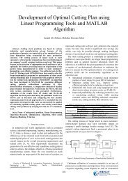
II. MODELING AN INVERTED PENDULUM<br />
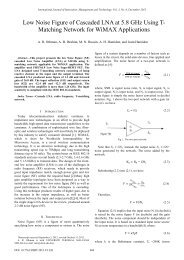
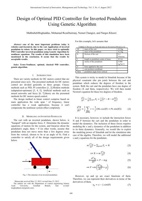
The cart with an inverted pendulum, shown below, is<br />
"bumped" with an impulse <strong>for</strong>ce, F. Determine the dynamic<br />
equations <strong>of</strong> motion <strong>for</strong> the system, and linearize about the<br />
pendulum's angle, theta = 0 (in other words, assume that<br />
pendulum does not move more than a few degrees away<br />
from the vertical, chosen to be at an angle <strong>of</strong> 0). Find a<br />
controller to satisfy all <strong>of</strong> the design requirements given<br />
below.<br />
For this example, let's assume that<br />
TABLE I: PHYSICAL PARAMETERS OF INVERTED PENDULUM<br />
M mass <strong>of</strong> the cart 0.5 kg<br />
m mass <strong>of</strong> the pendulum 0.2 kg<br />
b friction <strong>of</strong> the cart 0.1<br />
N/m/sec<br />
l length to pendulum center <strong>of</strong> mass 0.3 m<br />
I inertia <strong>of</strong> the pendulum 0.006<br />
kg*m^2<br />
F <strong>for</strong>ce applied to the cart<br />
x cart position coordinate<br />
theta pendulum angle from vertical<br />
This system is tricky to model in Simulink because <strong>of</strong> the<br />
physical constraint (the pin joint) between the cart and<br />
pendulum which reduces the degrees <strong>of</strong> freedom in the<br />
system. Both the cart and the pendulum have one degree <strong>of</strong><br />
freedom (X and theta, respectively). We will then model<br />
Newton's equation <strong>for</strong> these two degrees <strong>of</strong> freedom.<br />
<br />
∑<br />
<br />
<br />
<br />
<br />
<br />
1 1 <br />
<br />
<br />
(1)<br />
(2)<br />
It is necessary, however, to include the interaction <strong>for</strong>ces<br />
N and P between the cart and the pendulum in order to<br />
model the dynamics. The inclusion <strong>of</strong> these <strong>for</strong>ces requires<br />
modeling the x and y dynamics <strong>of</strong> the pendulum in addition<br />
to its theta dynamics. Generally, we would like to exploit<br />
the modeling power <strong>of</strong> Simulink and let the simulation take<br />
care <strong>of</strong> the algebra. There<strong>for</strong>e, we will model the additional<br />
x and y equations <strong>for</strong> the pendulum.<br />
<br />
∑ <br />
3<br />
<br />
<br />
4<br />
<br />
5<br />
<br />
6<br />
Fig. 1.The structure <strong>of</strong> an inverted pendulum.<br />
Manuscript received May 12, 2012; revised June 15, 2012.<br />
The authors are with the Department <strong>of</strong> control engineering Islamic<br />
Azad University, Gonabad Branch, Iran (e-mail:<br />
moghaddasm.m@gmail.com).<br />
However, xp and yp are exact functions <strong>of</strong> theta.<br />
There<strong>for</strong>e, we can represent their derivatives in terms <strong>of</strong> the<br />
derivatives <strong>of</strong> theta.<br />
<br />
(7)<br />
440
International Journal <strong>of</strong> Innovation, Management and Technology, Vol. 3, No. 4, August 2012<br />
<br />
<br />
<br />
<br />
<br />
<br />
<br />
<br />
<br />
<br />
<br />
<br />
<br />
<br />
<br />
<br />
<br />
<br />
<br />
<br />
<br />
<br />
<br />
8<br />
9<br />
10<br />
11<br />
12<br />
These expressions can then be substituted into the<br />
expressions <strong>for</strong> N and P. Rather than continuing with<br />
algebra here, we will simply represent these equations in<br />
Simulink.<br />
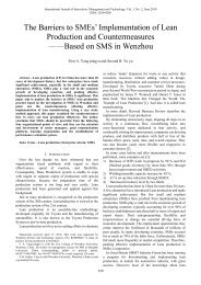
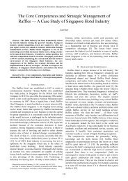
Simulink can work directly with nonlinear equations, so it<br />
is unnecessary to linearize these equations.<br />
combined with pc possibility and the next generation comes<br />
in to being.<br />
By considering that during the past phases <strong>of</strong> gene it may<br />
cause noise,in fact, this phase is a Random noise which<br />
causes a small pc possibility <strong>for</strong> every bit.<br />
For GA,in every problem,a fitness function must be<br />
defined. F functions can be described as follows:<br />
F = OverShoot + Ess (13)<br />
F = A ∗ OverShoot + B ∗ Ess (14)<br />
F = e A∗OverShoot +B∗Ess (15)<br />
In this problem, the aim is to minimize every function <strong>of</strong><br />
F .As GA Has the ability to be maximized, hence, fitness<br />
function is defined as below.<br />
Fitnes = K − F (16)<br />
Fitnes = 1 F<br />
(17)<br />
If the fitness function is selected from an equation (16)<br />
constant parameter k must be regulated in a wayThat causes<br />
no harm to the problem. If k is a small number, fitness will<br />
be negative and <strong>for</strong> the capital k, the fitness <strong>of</strong> all the<br />
individuals in the society will be approximated .In this paper,<br />
some equations have been used.<br />
Fig. 2.The block diagram <strong>of</strong> an inverted pendulum.<br />
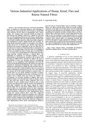
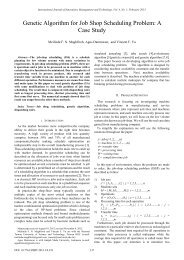
III. GENETIC ALGORITHM<br />
In this algorithm, first <strong>of</strong> all, we create some random<br />
populations. Every individual (gene) In GA is considered in<br />
the <strong>for</strong>m <strong>of</strong> binary strings then, fitness <strong>for</strong> every individual<br />
is chosen with regard to its fitness.<br />
For creating the next generation, three stages is the<br />
selection phase, which consists <strong>of</strong> different phases,<br />
including ranking, proportional and… The second phase is<br />
the combination phase. In this phase, the two parents are<br />
Fig. 3.Chart <strong>of</strong> genetic algorithm.<br />
0.35<br />
0.12<br />
0.3<br />
0.1<br />
0.25<br />
0.08<br />
Angle(rad)<br />
0.2<br />
0.15<br />
0.1<br />
Angle(rad)<br />
0.06<br />
0.04<br />
0.05<br />
0.02<br />
0<br />
0<br />
-0.05<br />
0 1 2 3 4 5 6 7 8 9 10<br />
Time(s)<br />
-0.02<br />
0 1 2 3 4 5 6 7 8 9 10<br />
Time(s)<br />
0.12<br />
0.7<br />
0.1<br />
0.6<br />
0.08<br />
0.5<br />
Angle(rad)<br />
0.06<br />
0.04<br />
Angle(rad)<br />
0.4<br />
0.3<br />
0.2<br />
0.02<br />
0.1<br />
0<br />
0<br />
-0.02<br />
0 1 2 3 4 5 6 7 8 9 10<br />
Time(s)<br />
-0.1<br />
0 1 2 3 4 5 6 7 8 9 10<br />
Time(s)<br />
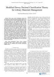
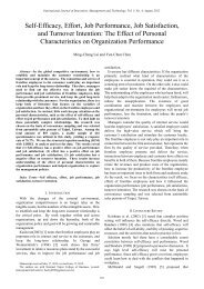
Fig. 4. results <strong>of</strong> system by Populations size=50 ; binary strings =16bit<br />
441
Angle(rad)<br />
Angle(Rad)<br />
Angle(Rad)<br />
Angle(Rad)<br />
International Journal <strong>of</strong> Innovation, Management and Technology, Vol. 3, No. 4, August 2012<br />
0.35<br />
0.1<br />
0.3<br />
0.08<br />
0.25<br />
0.06<br />
0.2<br />
0.04<br />
0.15<br />
0.02<br />
0.1<br />
0.05<br />
0<br />
0<br />
-0.02<br />
-0.05<br />
-0.04<br />
0 1 2 3 4 5 6 7<br />
Time(secend)<br />
-0.1<br />
0 1 2 3 4 5 6 7<br />
Time(Second)<br />
0.6<br />
0.5<br />
0.4<br />
0.8<br />
0.7<br />
0.6<br />
0.5<br />
0.3<br />
0.2<br />
0.4<br />
0.3<br />
0.2<br />
0.1<br />
0<br />
-0.1<br />
0.1<br />
0<br />
-0.1<br />
-0.2<br />
0 1 2 3 4 5 6 7<br />
0 1 2 3 4 5 6 7<br />
Time(Second)<br />
Time(Second)<br />
Fig. 5. Results <strong>of</strong> system by populations size=25; binary strings =8bit.<br />
Parameter<br />
TABLE II: TUNING PARAMETER<br />
Value<br />
Lower bound [Kp Ki Kd] [0 0 0]<br />
Upper bound [Kp Ki Kd] [100 100 100]<br />
Stopping criteria (Iterations) 100<br />
Population Size 50 and 25<br />
Crossover Fraction 0.8<br />
Mutation Fraction 0.01<br />
binary strings<br />
IV. CONCLUSION<br />
16bit and 8 bit<br />
Parameters adjustment at different problems takes more<br />
time up by hard mathematical calculating. At this paper was<br />
tried one simple application from Genetic algorithm<br />
considered by controlengineeringproblem. We can find the<br />
optimal answer with Genetic algorithm .This answer should<br />
be careful and simple rarely acceptable.<br />
REFERENCES<br />
[1] J. Nuo and W. Hui, “Nonlinear control <strong>of</strong> an invertedpendulum<br />
system based on slinding mode method,” ACTA Analysis<br />
Functionalisapplicata, vol. 9, no. 3, pp.234-237, 2008.<br />
[2] O. T. Altinoz and A. E. Yilmaz, “Gerhard Wilhelm Weber Chaos<br />
Particle Swarm Optimized <strong>PID</strong> <strong>Controller</strong> <strong>for</strong> the <strong>Inverted</strong> <strong>Pendulum</strong><br />
System,” presented at 2nd International Conference on Engineering<br />
ptimization September 6-9, 2010, Lisbon, Portugal.<br />
[3] W. Wang, “Adaptive fuzzy sliding mode control <strong>for</strong> inverted<br />
pendulum,” in Proceedings <strong>of</strong> the Second Symposium International<br />
Computer Science and Computational Technology(ISCSCT ’09)<br />
uangshan, P. R. China, 26-28, Dec. pp. 231-234, 2009.<br />
[4] V. Sukontanakarn and M. Parnichkun, “ Real-Time optimal control<br />
<strong>for</strong> rotary inverted pendulum, ”American Journal <strong>of</strong> Applied Science,<br />
vol. 6, no. 6, pp. 1106-1115, 2009.<br />
[5] A. Bogdanov, “<strong>Optimal</strong> control <strong>of</strong> a double inverted pendulum on a<br />
cart technical report,” CSE-04-006 December 2004.<br />
[6] T. Sugie and K. Fujimoto, “<strong>Controller</strong> design <strong>for</strong> an inverted<br />
pendulum based on approximate linearization,” Int. J. <strong>of</strong> Robust and<br />
Nonlinear Control, vol. 8, no 7, pp. 585-597, 1998.<br />
[7] S-Ichihorikawa and M. Yamaguchi, Takeshi Fuzzy Control <strong>for</strong><br />
<strong>Inverted</strong> <strong>Pendulum</strong> <strong>Using</strong> Fuzzy Neural Networks, January 10, 1995.<br />
[8] I. H. Zadeh and S. Mobayen, “ PSO-based controller <strong>for</strong> balancing<br />
rotary inverted pendulum, ” J. AppliedSci., vol. 16, pp. 2907-2912<br />
2008.<br />
[9] J. Lam, “Control <strong>of</strong> an inverted pendulum,” University <strong>of</strong> Cali<strong>for</strong>nia,<br />
Santa Barbara, 10 June 2004 Yasar Beceriklia, B. KorayCelikb Fuzzy<br />
control <strong>of</strong> inverted pendulum and concept <strong>of</strong> stability using Java<br />
application Mathematical and Computer Modelling vol. 46, pp. 24–37,<br />
2006.<br />
Mahbubeh Moghaddas received the MS degree in<br />
control engineering from the control department, Islamic<br />
Azad University <strong>of</strong> Gonabad, Iran, in 2009 and 2011,<br />
respectively. His research interests focus on fuzzy<br />
systems and Genetic Algorithm<br />
Mohamad Reza Dastranj received the MS degree in<br />
control engineering from the control department,<br />
Islamic Azad University <strong>of</strong> Gonabad,Iran, in 2009 and<br />
2011, respectively. His research interests focus on<br />
fuzzy systems and Genetic Algorithm<br />
N. Changizi was born on 19/01/1987-Amol, Iran. I<br />
received the M.S degree in control engineering from<br />
Islamic Azad University, Gonabad Branch, Iran in<br />
2011. From 2009 to 2011, he was the teacher <strong>of</strong><br />
department <strong>of</strong> electrical engineering in IAUG, Iran.<br />
He is member <strong>of</strong> young researcher club IAU in<br />
Iran.his current research interests include design <strong>of</strong><br />
fuzzy logic controller as well as design <strong>of</strong> currentmode<br />
and mixed signal circuits and systems. He has<br />
also dealt with applications <strong>of</strong> genetic algorithm and<br />
sliding mode control.<br />
Nargeskhori received the MS degree in control engineering from the<br />
control department, Islamic Azad University <strong>of</strong> Gonabad, Iran, in 2009 and<br />
2011, respectively. His research interests focus on fuzzy systems and<br />
Genetic Algorithm<br />
442