Implementation of GB Interface using Internet Protocol
Implementation of GB Interface using Internet Protocol
Implementation of GB Interface using Internet Protocol

Create successful ePaper yourself
Turn your PDF publications into a flip-book with our unique Google optimized e-Paper software.
2nd National Conference on Information and Communication Technology (NCICT) 2011<br />
Proceedings published in International Journal <strong>of</strong> Computer Applications® (IJCA)<br />
<strong>Implementation</strong> <strong>of</strong> <strong>GB</strong> <strong>Interface</strong> <strong>using</strong> <strong>Internet</strong><br />
<strong>Protocol</strong><br />
Kshipra Chowdhary<br />
VIT, Pune<br />
666-Upper Indiranagar,<br />
Bibewadi, Pune-37<br />
ABSTRACT<br />
The GSM technology has lower data rate around 9.6kbps. Also<br />
it proves expensive for bursty traffic utilization. Therefore to<br />
enhance the data capacity <strong>of</strong> GSM and mitigate some <strong>of</strong> its<br />
limitations, mobile technology <strong>using</strong> general packet radio<br />
service (GPRS) has been developed. GPRS adds packetswitched<br />
capabilities to existing GSM and TDMA networks.<br />
The circuit-switched technology has a long and successful<br />
history but it is inefficient for short data transactions and<br />
always-on service. The packet switched technology has grown<br />
in importance with the rise <strong>of</strong> the <strong>Internet</strong> and <strong>Internet</strong> protocol<br />
(IP). The Gb interface carries the GPRS traffic and signalling<br />
between the GSM radio network (BSS) and the GPRS network.<br />
Frame Relay based network services is used for this interface.<br />
However because <strong>of</strong> congestion problem and the lower<br />
throughput, this interface has been implemented <strong>using</strong> internet<br />
protocol called as the Gb over IP. This paper discusses the basic<br />
architecture <strong>of</strong> GPRS, pooling concept and the implementation<br />
<strong>of</strong> the Gb interface <strong>using</strong> internet protocol. After implementation<br />
the data rate increases to few mbps. This can be achieved<br />
through increased capacity utilization,network-level redundancy,<br />
efficient mobility and simplified O&M.<br />
Keywords<br />
GPRS, IP, Gb over IP.<br />
1. INTRODUCTION<br />
In early 2000, only a small portion <strong>of</strong> GSM subscribers used<br />
data services because existing GSM systems do not support easy<br />
access, high data rate and attractive prices. GSM operators must<br />
<strong>of</strong>fer better services to stimulate the demand. The solution is<br />
General Packet Radio Service (GPRS). GPRS reuses the<br />
existing GSM infrastructure to provide end-to-end packetswitched<br />
services. GPRS standardization was initiated by<br />
ETSI/SMG in 1994. The main set <strong>of</strong> GPRS specifications was<br />
approved by SMG #25 in 1997, and was complete in 1999.<br />
GPRS products were developed in 1999, and service<br />
deployment has been in progress. GPRS core network has also<br />
been developed with IS-136 TDMA systems, and is anticipated<br />
to evolve as the core network for the third generation mobile<br />
systems.<br />
The Gb interface connects the BSS and the SGSN. It allows<br />
for the exchange <strong>of</strong> signalling information and user data. Many<br />
users are multiplexed on the same physical resource. Resources<br />
are allocated to the user only during activity periods; after these<br />
periods, resources are immediately released and reallocated to<br />
other users. This is in contrast to the GSM „A‟ interface where<br />
one user has the sole use <strong>of</strong> a dedicated physical resource during<br />
the lifetime <strong>of</strong> a call. No dedicated physical resources are<br />
Indraneil Deshmukh<br />
VIT, Pune<br />
666-Upper Indiranagar,<br />
Bibewadi, Pune-37<br />
Sangeeta Kurundhkar<br />
VIT, Pune<br />
666-Upper Indiranagar,<br />
Bibewadi, Pune-37<br />
required to be allocated for signalling purposes. Signalling and<br />
user data are sent in the same transmission plane.<br />
It is a system and method in a General Packet Radio Service<br />
(GPRS) network for automatically configuring Network Service<br />
Entity Identifiers (NSEIs) in a Base Station System (BSS) and<br />
Serving GPRS Support Node (SGSN) when the BSS is<br />
reconfigured.<br />
The Gb interface between the BSS and the SGSN is modified<br />
to operate <strong>using</strong> the <strong>Internet</strong> <strong>Protocol</strong> (IP), and the BSS and the<br />
SGSN are configured to run on IP. Whenever a new Network<br />
Service Entity (NSE) is added to an existing BSS, or a new BSS<br />
is added to the network, the BSS automatically sends a modified<br />
Network Service (NS′)-Reset message to the SGSN requesting<br />
an NSEI. The SGSN dynamically allocates a free NSEI from a<br />
pool <strong>of</strong> NSEIs and sends it to the BSS. When an NSE is<br />
removed from the BSS, the BSS automatically sends a modified<br />
NS′-Reset message to the SGSN to free an NSEI. The SGSN deallocates<br />
the NSEI, and returns the NSEI to the pool <strong>of</strong> free<br />
NSEIs. All related entries for Base Station System GPRS<br />
<strong>Protocol</strong> (BSSGP) Virtual Circuit Identifiers (BVCIs) under the<br />
de-allocated NSEI are also removed by the SGSN.<br />
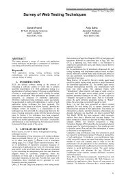
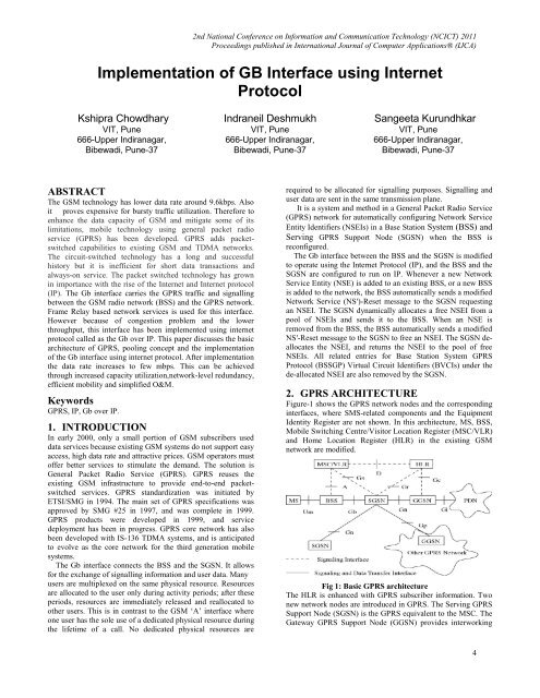
2. GPRS ARCHITECTURE<br />
Figure-1 shows the GPRS network nodes and the corresponding<br />
interfaces, where SMS-related components and the Equipment<br />
Identity Register are not shown. In this architecture, MS, BSS,<br />
Mobile Switching Centre/Visitor Location Register (MSC/VLR)<br />
and Home Location Register (HLR) in the existing GSM<br />
network are modified.<br />
Fig 1: Basic GPRS architecture<br />
The HLR is enhanced with GPRS subscriber information. Two<br />
new network nodes are introduced in GPRS. The Serving GPRS<br />
Support Node (SGSN) is the GPRS equivalent to the MSC. The<br />
Gateway GPRS Support Node (GGSN) provides interworking<br />
4
with external packet-switched networks, and is connected with<br />
SGSNs via an IP-based GPRS backbone network. The MS and<br />
the BSS communicates through the Um interface. The BSS and<br />
the SGSN are connected by the Gb interface with Frame Relay.<br />
Within the same GPRS network, SGSNs/GGSNs are connected<br />
through the Gn <strong>Interface</strong>. When SGSN and GGSN are in<br />
different GPRS networks, they are interconnected via the Gp<br />
interface. The GGSN connects to the external networks through<br />
the Gi interface. The MSC/VLR communicates with the BSS<br />
<strong>using</strong> the existing GSM A interface, and with the SGSN <strong>using</strong><br />
the Gs interface. The HLR connects to SGSN with the Gr<br />
interface and to GGSN with Gc interfaces. Both Gr and Gc<br />
follow GSM Mobile Application Part (MAP) protocol defined in<br />
GSM 09.02 [4]. The HLR and the VLR are connected through<br />
the existing GSM D interface. <strong>Interface</strong>s A, Gs, Gr, GC, and D<br />
are used for signalling without involving user data transmission<br />
in GPRS. Note that the A interface is used for both signalling<br />
and voice transmission in GSM. <strong>Interface</strong>s Um, Gb, Gn, Gp and<br />
Gi are used for both signalling and transmission in GPRS.<br />
2.1 GPRS in BSS<br />
GPRS uses the radio interface efficiently in two ways. Firstly, it<br />
enables a fast method for reserving radio channels. Secondly,<br />
the benefit <strong>of</strong> GPRS is the sharing <strong>of</strong> resources with circuit<br />
switched connections. GPRS packets can be transmitted in the<br />
free periods between circuit switched calls. Furthermore, GPRS<br />
provides immediate connectivity and high throughput. The main<br />
functions <strong>of</strong> the BSC with GPRS are to:<br />
� manage GPRS-specific radio network configuration<br />
� control access to GPRS radio resources<br />
� share radio resources between GPRS and circuit<br />
switched use<br />
� handle signalling between the MS, BTS and Serving<br />
GPRS Support Node<br />
2.2 Pooling Concept<br />
[Reference no: 1/287 01-F<strong>GB</strong> 101 256 Uen Rev A 2006-08-<br />
23]<br />
Traditionally in GPRS-based packet data networks, each<br />
SGSN is wholly responsible for its own service area. If the<br />
SGSN becomes unavailable for any reason, subscribers in the<br />
service area no longer have access to packet data services.<br />
SGSN Pool – which is standardized for GSM and WCDMA<br />
networks in 3GPP R5 –addresses this issue by introducing a<br />
more flexible and resource-efficient architecture with built-in<br />
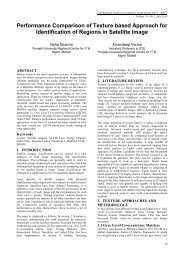
network redundancy. With SGSN Pool, all the SGSNs in the<br />
network work together and the capacity load between them is<br />
distributed by the BSCs and RNCs. All BSCs and RNCs serving<br />
GSM and WCDMA radio access networks are connected to all<br />
SGSNs in the pool, as shown in Fig-2 below. If any SGSN<br />
become unavailable, any attached mobile devices will be<br />
automatically rerouted to another SGSN in the pool.<br />
2nd National Conference on Information and Communication Technology (NCICT) 2011<br />
Proceedings published in International Journal <strong>of</strong> Computer Applications® (IJCA)<br />
Fig 2: SGSN Pool overview<br />
3. <strong>GB</strong> OVER IP<br />
3.1 Technical Field <strong>of</strong> the Invention<br />
This invention relates to telecommunication systems and, more<br />
particularly, to a system and method in a General Packet Radio<br />
Service (GPRS) network for <strong>using</strong> a Gb interface, which has<br />
been modified to operate <strong>using</strong> the <strong>Internet</strong> <strong>Protocol</strong> (IP), to<br />
automatically configure Network Service Entity Identifiers<br />
(NSEIs) in a Base Station System (BSS) and a Serving GPRS<br />
Support Node (SGSN)<br />
3.2 Description <strong>of</strong> related art<br />
� The Gb interface is an interface in the GPRS<br />
network between the SGSN and the BSS based<br />
on the connection-oriented Frame Relay protocol.<br />
The protocol stack currently comprises an L1<br />
physical layer (related to Frame Relay), a<br />
Network Service (NS) layer, and a Base Station<br />
System GPRS <strong>Protocol</strong> (BSSGP) layer. The NS<br />
layer is divided into two sub-layers. The upper<br />
NS sub-layer is called the Network Service<br />
Control (NSC), and is like the glue with the<br />
BSSGP layer above. The lower NS sub-layer is<br />
called SubNetwork Service (SNS), and is like the<br />
glue with the underlying Frame Relay structure.<br />
� solution is to encapsulate the Frame Relay<br />
information in IP packets sent between the two<br />
nodes. Also, there are existing networks <strong>using</strong> the<br />
Gb interface over Frame Relay, and any new<br />
interface needs to be backward compatible to<br />
support these Frame Relay networks. Therefore,<br />
the new interface must have a protocol stack that<br />
supports both Frame Relay and IP.<br />
� It would be advantageous to have an interface<br />
between the BSS and the SGSN that is based on<br />
the IP protocol. There is a larger pool <strong>of</strong> products<br />
available for IP than for Frame Relay, and the use<br />
<strong>of</strong> IP allows the use <strong>of</strong> several different layer 1<br />
and layer 2 technologies (e.g., Frame Relay,<br />
Ethernet, fiber optics, etc.). In essence, the Gb<br />
interface would become carrier-independent and<br />
much more flexible in terms <strong>of</strong> routing. It would<br />
also be easier to maintain.<br />
� Basing the interface on IP would provide<br />
additional flexibility and features that exist in IP<br />
but not in Frame Relay. For example, an<br />
5
automatic configuration method would enable<br />
BSS components to be changed, or new BSSs to<br />
be added to the network while automatically<br />
configuring the SGSN to handle the new network<br />
configuration. In the existing Frame Relay-based<br />
Gb interface, information is carried between the<br />
nodes <strong>using</strong> virtual circuits. These connections<br />
must be established manually.<br />
� The SGSN must know in advance which fictional<br />
entity is going to be on the other side <strong>of</strong> each<br />
virtual circuit, so when there is a change to the<br />
BSS, a technician must physically go to the<br />
SGSN and enter the same data that was set up in<br />
the BSS. For example, identifying numbers are<br />
assigned to each functional entity, and the<br />
technician must manually deconflict these<br />
numbers by making sure that the numbers that he<br />
assigns in the BSS are not already assigned in the<br />
SGSN to other entities.<br />
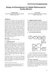
3.3 Transmission plane on <strong>GB</strong> interface.<br />
Transmission over the Gb interface was based on frame relay.<br />
Point-to-point (PTP) physical lines or an intermediate frame<br />
relay network were used to connect the SGSN and the BSS.<br />
Fig 3: Transmission plane on Gb interface<br />
3.3.1 NS Layer<br />
The NS layer provides a frame-based, multiplexed link layer<br />
transport mechanism across the Gb interface that relies on the<br />
frame relay protocol. The NS layer has been split into two<br />
sublayers, subnetwork service (SNS) and network service<br />
control (NSC) in order to make one sublayer independent <strong>of</strong> the<br />
intermediate transmission network. SNS is based on frame relay<br />
but NSC is independent <strong>of</strong> the transmission network. Later, it<br />
will be possible to change the transmission network (e.g., with<br />
an IP network) without changing the NSC sublayer.<br />
Peer-to-peer communication across the Gb interface between the<br />
two remote NS entities in the BSS and the SGSN is performed<br />
over virtual connections. The NS layer is responsible for the<br />
management <strong>of</strong> the virtual connections between the BSS and the<br />
SGSN (verification <strong>of</strong> the availability <strong>of</strong> the virtual connections,<br />
initialization, and restoring <strong>of</strong> a virtual connection). It provides<br />
information on the status and the availability <strong>of</strong> the virtual<br />
connections to the BSSGP layer. It ensures the distribution <strong>of</strong><br />
upper-layer PDUs between the different possible virtual<br />
connections (load-sharing function). SNS provides access to<br />
the intermediate transmission network (i.e., the frame relay<br />
network). NSC is responsible for upper-layer data (BSSGP<br />
2nd National Conference on Information and Communication Technology (NCICT) 2011<br />
Proceedings published in International Journal <strong>of</strong> Computer Applications® (IJCA)<br />
PDUs) transmission, load sharing, and virtual connection<br />
management.<br />
3.3.2 BSSGP Principle<br />
The BSSGP layer ensures the transmission <strong>of</strong> upper-layer data<br />
(LLC PDUs) from the BSS to the SGSN or from the SGSN to<br />
the BSS. It ensures the transmission <strong>of</strong> GMM signalling and NM<br />
signalling.The peer-to-peer communication across the Gb<br />
interface between the two remote BSSGP entities in the BSS and<br />
the SGSN is performed over virtual connections. There is one<br />
virtual connection per cell at BSSGP layer. Each virtual<br />
connection can be supported by several layer 2 links between the<br />
SGSN and the BSS. The BSSGP layer is responsible for the<br />
management <strong>of</strong> the virtual connections between the SGSN and<br />
the BSS (verification <strong>of</strong> the availability <strong>of</strong> the virtual<br />
connections, initialization and restoring <strong>of</strong> a virtual connection).<br />
The BSSGP layer also ensures the data flow control between the<br />
SGSN and the BSS. There is a one-to-one relationship between<br />
the BSSGP in the SGSN and in the BSS. That means if one<br />
SGSN handles several BSSs, the SGSN must have one BSSGP<br />
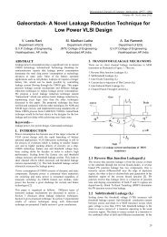
protocol machine for each BSS. Figure-4 shows the position <strong>of</strong><br />
the BSSGP layer within the BSS and the SGSN.<br />
Fig 4: Position <strong>of</strong> the BSSGP layer within the BSS and<br />
SGSN<br />
4. CONCLUSION<br />
� The present invention uses a Gb-over-IP interface<br />
(Gb′) between the SGSN and the BSS to implement an<br />
automatic “plug and play” configuration methodology.<br />
The Gb′ interface implements a protocol stack in the<br />
SGSN and the BSS that includes a User Datagram<br />
<strong>Protocol</strong> (UDP) layer over an IP layer. Data packets<br />
are then transmitted between the BSS and the SGSN<br />
over a connectionless IP network. The data packets<br />
carry information between functional entities in the<br />
SGSN and functional entities in the BSS.<br />
� The protocol stack includes a Base Station System<br />
GPRS <strong>Protocol</strong> (BSSGP) protocol layer that provides<br />
radio-related, Quality-<strong>of</strong>-Service (QoS), and routing<br />
information that is required to transmit user data<br />
between the BSS and the SGSN. The stack also<br />
includes a modified Network Services (NS′) layer<br />
which is divided into an upper NS′ Network Service<br />
Control (NS′-NSC) sub-layer and a lower NS′-Sub-<br />
Network Service (NS′-SNS) sub-layer. The NS′-NSC<br />
sub-layer maps to the BSSGP layer and manages<br />
functional entities therein. The NS′-SNS sub-layer<br />
6
maps to the UDP and IP layers and provides access to<br />
the IP network. A single UDP port is reserved to make<br />
the NS′ layer and the BSSGP layer act as an<br />
application over the IP stack.<br />
� The system and method <strong>of</strong> the present invention<br />
automatically configures Network Service Entity<br />
Identifiers (NSEIs) in the BSS and the SGSN when<br />
the BSS is reconfigured. The BSS utilizes the Gbover-IP<br />
interface to automatically send a request for an<br />
NSEI from the BSS to the SGSN whenever a new<br />
Network Service Entity (NSE) is added to an existing<br />
BSS. Whenever a new BSS is added to the network,<br />
the new BSS automatically sends a request for an<br />
NSEI to the SGSN. The SGSN then allocates a free<br />
NSEI, and sends the allocated NSEI from the SGSN to<br />
the BSS. The allocated NSEI is recorded in the BSS<br />
and the SGSN. The NSEI may be dynamically<br />
allocated from a pool <strong>of</strong> free NSEIs in the SGSN.<br />
� The system and method <strong>of</strong> the present invention also<br />
automatically de-allocates NSEIs when an NSE is<br />
removed from the BSS. In this aspect, the BSS<br />
automatically sends a request from the BSS to the<br />
SGSN to free an NSEI whenever an NSE is removed<br />
from the BSS. The SGSN de-allocates the NSEI, and<br />
returns the NSEI to the pool <strong>of</strong> free NSEIs.<br />
One <strong>of</strong> the key trends in mobile communications today is<br />
the rapid growth in the number <strong>of</strong> data users. At the same time, a<br />
host <strong>of</strong> new data-oriented services are being introduced that<br />
require real-time performance, including IP Telephony. These<br />
trends highlight the need to improve data network efficiency to<br />
ensure right service quality and superior user experience. The<br />
quality <strong>of</strong> user experience is defined not only by the applications<br />
available, but also by network factors such as availability and<br />
resource utilization. Thus the implementation <strong>of</strong> the Gb link<br />
between the BSS and SGSN in the GPRS network <strong>using</strong> IP<br />
helps mobile operators to meet these changing demands. This<br />
can be achieved through increased capacity utilization, networklevel<br />
redundancy, efficient mobility and simplified O&M. The<br />
results are improved customer satisfaction, and lower churn,<br />
twinned with better pr<strong>of</strong>itability through lower capital and<br />
operational expenditure.<br />
2nd National Conference on Information and Communication Technology (NCICT) 2011<br />
Proceedings published in International Journal <strong>of</strong> Computer Applications® (IJCA)<br />
4.2 Future Scope<br />
GPRS Phase 2 development includes the following features:<br />
� IP and X.25 interfaces to packet data network.<br />
� Static and dynamic IP address allocation.<br />
� Anonymous access.<br />
� Security i.e. authentification and ciphering<br />
5. ACKNOWLEDGEMENT<br />
Our special thanks to Mr K.Bhattacharjee <strong>of</strong> Nokia Siemens<br />
Networks for his valuable guidance and support in the<br />
development <strong>of</strong> this template<br />
6. REFERENCES<br />
[1] General Packet Radio Service(GPRS),Mobile Station<br />
Serving Support Node (SGSK): Subnetwork Dependent<br />
Convergeit <strong>Protocol</strong> (SNDCP) (Release 1599)<br />
[2] Digital cellular telecommunications system (Phase 2+);<br />
General Packet Radio Service (GPRS); Overall description<br />
<strong>of</strong> the GPRS radio interface; Stage 2 (3GPP TS 03.64<br />
version 8.9.0 Release 1999).<br />
[3] Halonen T, Melero J., Romero J, GSM, GPRS 8c EDGE<br />
Performance: Evolution towards 3G UMTS, John Wiley &<br />
Sons, 2002<br />
[4] “IP Mobility Support,” C. Perkin, IETF, RFC 2002,<br />
October 1996.<br />
[5] TCP/IP Illustrated, Vol. 1,The <strong>Protocol</strong>s, W.<br />
RichardStevens,Addison-Wesley Longman, Reading,<br />
Massachusetts, 1999<br />
[6] <strong>Internet</strong> <strong>Protocol</strong>,” Jon Postel, RFC791, September 1981<br />
[7] Gb over IP by Ericsson AB 2006 Public 1/287 01-F<strong>GB</strong> 101<br />
256 Uen Rev A 2006-08-23<br />
7