GRC Eng. N.C. GAS SOLENOID VALVES WITH ... - UK Metering
GRC Eng. N.C. GAS SOLENOID VALVES WITH ... - UK Metering
GRC Eng. N.C. GAS SOLENOID VALVES WITH ... - UK Metering

Create successful ePaper yourself
Turn your PDF publications into a flip-book with our unique Google optimized e-Paper software.
G 921 - <strong>GRC</strong>... <strong>Eng</strong>. 07.06.04 MZ<br />
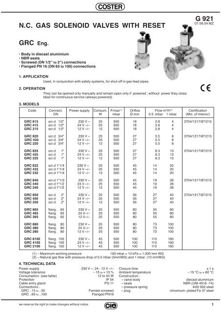
N.C. <strong>GAS</strong> <strong>SOLENOID</strong> <strong>VALVES</strong> <strong>WITH</strong> RESET<br />
G 921<br />
07.06.04 MZ<br />
<strong>GRC</strong> <strong>Eng</strong>.<br />
• Body in diecast aluminium<br />
• NBR seals<br />
• Screwed (DN 1/2” to 2”) connections<br />
• Flanged PN 16 (DN 65 to 100) connections<br />
1. APPLICATION<br />
Used, in conjunction with safety systems, for shut-off in gas feed pipes.<br />
2. OPERATION<br />
They can be opened only manually and remain open only if powered ; without power they close.<br />
Ideal for continuous service (always powered).<br />
3. MODELS<br />
Code Connect. Power supply Consum. P.max (1) Orifice Flow m 3 /h (2) Certification<br />
DN W mbar Ø mm 0.5 mbar 1 mbar (Min. of Interior)<br />
<strong>GRC</strong> 815 scr.d 1/2" 230 V ~ 25 500 18 2.8 4 3704/1217/87/215<br />
<strong>GRC</strong> 415 scr.d 1/2" 24 V ~/– 25 500 18 2.8 4<br />
<strong>GRC</strong> 215 scr.d 1/2" 12 V ~/– 12 500 18 2.8 4<br />
<strong>GRC</strong> 820 scr.d 3/4" 230 V ~ 25 500 27 5.5 8 3704/1217/87/215<br />
<strong>GRC</strong> 420 scr.d 3/4" 24 V ~/– 25 500 27 5.5 8<br />
<strong>GRC</strong> 220 scr.d 3/4" 12 V ~/– 12 500 27 5.5 8<br />
<strong>GRC</strong> 825 scr.d 1" 230 V ~ 25 500 27 8.3 13 3704/1217/87/215<br />
<strong>GRC</strong> 425 scr.d 1" 24 V ~/– 25 500 27 8.3 13<br />
<strong>GRC</strong> 225 scr.d 1" 12 V ~/– 12 500 27 8.3 13<br />
<strong>GRC</strong> 832 scr.d 1"1/4 230 V ~ 25 500 45 14 20<br />
<strong>GRC</strong> 432 scr.d 1"1/4 24 V ~/– 25 500 45 14 20<br />
<strong>GRC</strong> 232 scr.d 1"1/4 12 V ~/– 12 500 45 14 20<br />
<strong>GRC</strong> 840 scr.d 1"1/2 230 V ~ 25 500 45 19 28 3704/1217/87/215<br />
<strong>GRC</strong> 440 scr.d 1"1/2 24 V ~/– 25 500 45 19 28<br />
<strong>GRC</strong> 240 scr.d 1"1/2 12 V ~/– 12 500 45 19 28<br />
<strong>GRC</strong> 850 scr.d 2" 230 V ~ 25 500 56 27 40 3704/1217/87/215<br />
<strong>GRC</strong> 450 scr.d 2" 24 V ~/– 25 500 56 27 40<br />
<strong>GRC</strong> 250 scr.d 2" 12 V ~/– 12 500 56 27 40<br />
<strong>GRC</strong> 865 flang. 65 230 V ~ 25 500 80 55 80<br />
<strong>GRC</strong> 465 flang. 65 24 V~/– 25 500 80 55 80<br />
<strong>GRC</strong> 265 flang. 65 12 V~/– 25 500 80 55 80<br />
<strong>GRC</strong> 880 flang. 80 230 V ~ 25 500 80 73 100<br />
<strong>GRC</strong> 480 flang. 80 24 V~/– 25 500 80 73 100<br />
<strong>GRC</strong> 280 flang. 80 12 V ~/– 25 500 80 73 100<br />
<strong>GRC</strong> 8100 flang. 100 230 V ~ 45 500 100 110 160<br />
<strong>GRC</strong> 4100 flang. 100 24 V ~/– 45 500 100 110 160<br />
<strong>GRC</strong> 2100 flang. 100 12 V ~/– 45 500 100 110 160<br />
(1) – Maximum working pressure 100 mbar = 10 kPa = 1,000 mm WG<br />
(2) – Natural gas flow with pressure drop of 0.5 mbar (5mmWG) and 1 mbar (10 mmWG)<br />
4. TECHNICAL DATA<br />
Power supply 230 V ~, 24 - 12 V ~/–<br />
Voltage tolerance – 15 to + 10 %<br />
Consumption (see table)<br />
12 to 45 W<br />
Protection IP 54<br />
Cable entry gland PG 11<br />
Connections :<br />
<strong>GRC</strong> ..15 to ..50<br />
Female screwed<br />
<strong>GRC</strong> ..65 to ..100<br />
Flanged PN16<br />
Closure time<br />
≤ 1 s<br />
Ambient temperature – 15 °C to + 60 °C<br />
Construction :<br />
– valve body diecast aluminium<br />
– seals NBR (UNI 4916 -74)<br />
– pressure spring AISI 302 steel<br />
– plug chromium- plated Fe 37 steel<br />
we reserve the right to make changes without notice<br />
1
G 921 - <strong>GRC</strong>...<strong>Eng</strong>. 07.06.04 MZ<br />
5. INSTALLATION<br />
• It is preferable to position the valve downstream of the gas meter and outside the area traversed by the gas pipework.<br />
• If positioned in the open air it must be protected from rain.<br />
• Ensure that in the pipework there are no residues from soldering or from tapping or threading.<br />
• Check the alignment of the pipework connections and ensure that they are not subject to vibrations.<br />
• Pay attention to the flow direction marked on the valve body.<br />
• Valve can be installed in any position except that with the coil facing downwards.<br />
• Leave sufficient space for any future removal of the coil and around the valve itself for the circulation of air.<br />
• Avoid absolutely using the coil as a lever; instead use appropriate tools on the seating of the valve body.<br />
• On completion of the installation check the seals.<br />
• Power the coil and pull up the reset knob to open the valve.<br />
6. PRESSURE DROP<br />
7. OVERALL DIMENSIONS<br />
<strong>GRC</strong><br />
..15 to ..50<br />
<strong>GRC</strong><br />
..65 to ..100<br />
Type d A B C D E G H Wt<br />
DN mm mm mm mm mm mm mm kg<br />
..15 1/2" 77 22 83 164 18 – – 1.1<br />
..20 3/4" 96 22 83 180 25 – – 1.5<br />
..25 1" 96 22 83 180 25 – – 1.5<br />
..32 1"1/4 153 22 83 220 35 – – 2.4<br />
..40 1"1/2 153 22 83 220 35 – – 2.4<br />
..50 2" 156 22 83 230 39 – – 2.7<br />
..65 65 305 22 83 340 90 4 x18 145 7.6<br />
..80 80 305 22 83 340 90 8 x18 160 7.6<br />
..100 100 350 40 110 405 130 8 x18 180 17.0<br />
8. ELECTRICAL CONNECTIONS & MAINTENANCE<br />
The twin-wire power cable must be connected to the two poles of the rectifier terminal block housed in the union.<br />
On the junction box of the valves <strong>GRC</strong> 4100 (24 V) and <strong>GRC</strong> 2100 (12 V) there are two inputs marked with the<br />
simbols "L, N" and "+, –" :<br />
– with alternating current connect to input "L, N" ,<br />
– with direct current connect to terminals "+, –" , according to polarity.<br />
To remove the coil, first switch off the power and turn off the gas then unscrew the reset knob and the round knurled<br />
nut on top of the coil housing.<br />
In many cases the coils damaged by excessive voltages have only one or more rectifier diodes burnt out; if the<br />
resistance at the heads of the winding is 3,250 Ω, replace only the rectifier.<br />
WARNING : during normal operation of the gas valve the surface temperature of the coil can reach 70 °C, careful consideration<br />
must be taken when selecting suitable supply cables and the positioning of the valve in relation<br />
to surrounding materials.<br />
COSTER<br />
CONTROLLI<br />
TEMPERATURA<br />
ENERGIA<br />
COSTER TECNOLOGIE ELETTRONICHE S.p.A.<br />
Sede Legale: 25048 Edolo (BS) - Via Gen. Treboldi, 190<br />
Head Office & Sales<br />
Via San G.B. De La Salle, 4/a<br />
20132 - Milan<br />
Reg. Off. Central & Southern<br />
Via S. Longanesi, 14<br />
00146 - Roma<br />
Orders and Shipping<br />
Via Gen. Treboldi, 190/192<br />
25048 - Edolo (BS)<br />
E-mail: info@coster.info<br />
Tel. +39 022722121<br />
Fax +39 022593645<br />
Tel. +39 065573330<br />
Fax +39 065566517<br />
Tel. +39 0364773200<br />
Tel. +39 0364773202<br />
Fax +39 0364770016<br />
Web: www.coster.info<br />
RZ 15.02.02 Rev. : MZ 07.06.04<br />
ISO 9001:2000<br />
THE INTERNATIONAL CERTIFICATION NETWORK<br />
Registration Number: IT - 34674<br />
CSQ - Certificate N. 9115.COEE<br />
®<br />
D 33084<br />
2<br />
we reserve the right to make changes without notice