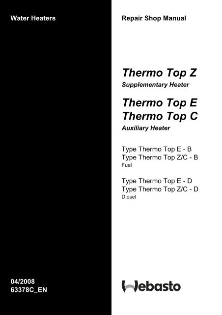
Thermo Top Z Thermo Top E Thermo Top C - Seatronic
Thermo Top Z Thermo Top E Thermo Top C - Seatronic
Thermo Top Z Thermo Top E Thermo Top C - Seatronic

You also want an ePaper? Increase the reach of your titles
YUMPU automatically turns print PDFs into web optimized ePapers that Google loves.
Water Heaters<br />
Repair Shop Manual<br />
<strong>Thermo</strong> <strong>Top</strong> Z<br />
Supplementary Heater<br />
<strong>Thermo</strong> <strong>Top</strong> E<br />
<strong>Thermo</strong> <strong>Top</strong> C<br />
Auxiliary Heater<br />
Type <strong>Thermo</strong> <strong>Top</strong> E - B<br />
Type <strong>Thermo</strong> <strong>Top</strong> Z/C - B<br />
Fuel<br />
Type <strong>Thermo</strong> <strong>Top</strong> E - D<br />
Type <strong>Thermo</strong> <strong>Top</strong> Z/C - D<br />
Diesel<br />
04/2008<br />
63378C_EN
List of Contents<br />
1 Introduction<br />
1.1 Scope and Purpose ............................................................................................................................... 101<br />
1.2 Meaning of Warnings, Cautions, and Notes .......................................................................................... 101<br />
1.3 Additional Documentation to be used .................................................................................................... 101<br />
1.4 Safety Information and Regulations....................................................................................................... 101<br />
1.4.1 Legal Provisions for Installation................................................................................................... 101<br />
1.4.2 General Safety Notes .................................................................................................................. 102<br />
1.5 Corrections and Improvements.............................................................................................................. 102<br />
2 General Description<br />
2.1 Combustion Air Fan Assembly .............................................................................................................. 202<br />
2.1.1 Combustion Air Fan..................................................................................................................... 202<br />
2.2 Burner Housing...................................................................................................................................... 202<br />
2.3 Burner Insert .......................................................................................................................................... 202<br />
2.4 Control Unit / Heat Exchanger ............................................................................................................... 203<br />
2.4.1 Control Unit.................................................................................................................................. 203<br />
2.4.2 Temperature Sensor.................................................................................................................... 203<br />
2.4.3 Overheat Protection..................................................................................................................... 203<br />
2.4.4 Heat Exchanger........................................................................................................................... 203<br />
2.5 Circulation Pump (<strong>Thermo</strong> <strong>Top</strong> E and C only)....................................................................................... 203<br />
2.6 Dosing Pump ......................................................................................................................................... 203<br />
3 Functional Description<br />
3.1 Functional Description <strong>Thermo</strong> <strong>Top</strong> Z (Supplementary Heater) ............................................................ 301<br />
3.1.1 Switch On / Starting..................................................................................................................... 301<br />
3.1.2 Heating Operation ....................................................................................................................... 301<br />
3.1.3 Switch Off / Deactivation ............................................................................................................. 301<br />
3.2 Functional Description <strong>Thermo</strong> <strong>Top</strong> E and C (Auxiliary Heater)............................................................ 302<br />
3.2.1 Switch On .................................................................................................................................... 302<br />
3.2.2 Heating Operation ....................................................................................................................... 302<br />
3.2.3 Switch Off .................................................................................................................................... 302<br />
3.2.4 Auxiliary Heater in Supplementary Heater Function.................................................................... 303<br />
4 Technical Data<br />
4.1 <strong>Thermo</strong> <strong>Top</strong> E........................................................................................................................................ 401<br />
4.2 <strong>Thermo</strong> <strong>Top</strong> Z/C (Heating Flow 5.0 kW)................................................................................................ 402<br />
4.3 <strong>Thermo</strong> <strong>Top</strong> Z/C (Heating Flow 5.2 kW)................................................................................................ 403
5 Troubleshooting<br />
5.1 General Fault Symptoms ...................................................................................................................... 501<br />
5.2 Error Messages during Functional Test with Diagnosis Tester <strong>Thermo</strong> Test ....................................... 502<br />
5.3 Malfunctions.......................................................................................................................................... 503<br />
5.3.1 Error Lockout by Malfunction of Heater ...................................................................................... 503<br />
5.3.2 Error Lockout due to Low or High Voltage.................................................................................. 503<br />
5.3.3 Error Lockout Reset.................................................................................................................... 503<br />
6 Functional Checkouts<br />
6.1 General ................................................................................................................................................. 601<br />
6.2 Functional Tests in the Vehicle............................................................................................................. 601<br />
6.2.1 Heating Operational Test (<strong>Thermo</strong> <strong>Top</strong> E and C)....................................................................... 601<br />
6.2.2 Timer Functional Test (<strong>Thermo</strong> <strong>Top</strong> E and C)............................................................................ 602<br />
6.2.3 Telestart T60 Functional Test (<strong>Thermo</strong> <strong>Top</strong> C) .......................................................................... 602<br />
6.2.4 Telestart T70 Functional Test (<strong>Thermo</strong> <strong>Top</strong> C and E)................................................................ 602<br />
6.2.5 Functional Test with Diagnosis Tester <strong>Thermo</strong> Test .................................................................. 603<br />
6.2.6 CO 2 Setting ................................................................................................................................ 604<br />
6.3 Repair Shop Level Testing.................................................................................................................... 604<br />
6.3.1 Components Testing................................................................................................................... 604<br />
7 Circuit Diagrams<br />
7.1 General .................................................................................................................................................. 701<br />
8 Servicing<br />
8.1 General ................................................................................................................................................. 801<br />
8.2 Work on the Heater............................................................................................................................... 801<br />
8.3 Work on the Vehicle.............................................................................................................................. 801<br />
8.4 Heater Test Run.................................................................................................................................... 801<br />
8.5 Servicing ............................................................................................................................................... 801<br />
8.6 Visual Inspections and Installation Regulations.................................................................................... 801<br />
8.6.1 Connection to Vehicle Cooling System....................................................................................... 801<br />
8.6.2 Connection to Vehicle Fuel System............................................................................................ 803<br />
8.6.3 Air Intake Muffler......................................................................................................................... 805<br />
8.6.4 Exhaust Line............................................................................................................................... 805<br />
8.7 Removal and Installation....................................................................................................................... 806<br />
8.7.1 Heater, Removal and Installation................................................................................................ 806<br />
8.7.2 Timer, Removal and Installation ................................................................................................. 806<br />
8.8 Initial Operation..................................................................................................................................... 806
9 Repair<br />
9.1 General .................................................................................................................................................. 901<br />
9.1.1 Work on Components after Disassembly .................................................................................... 901<br />
9.2 Disassembly and Assembly................................................................................................................... 902<br />
9.2.1 Circulation Pump, Replacement (<strong>Thermo</strong> <strong>Top</strong> E and C) ............................................................. 902<br />
9.2.2 Combustion Air Fan, Replacement.............................................................................................. 903<br />
9.2.3 Burner Insert with Glow Plug / Flame Sensor, Replacement ...................................................... 905<br />
9.2.4 Control Unit / Heat Exchanger with Burner Housing, Replacement ............................................ 905<br />
10 Packaging, Storage and Shipping<br />
10.1 General ................................................................................................................................................ 1001
List of Figures<br />
<strong>Thermo</strong> E and <strong>Top</strong> Z/C<br />
List of Figures<br />
501 Fault Symptoms ......................................................................................................................................... 501<br />
502 Error Messages.......................................................................................................................................... 502<br />
701 Control Unit Connector Pin Assignment (<strong>Thermo</strong> <strong>Top</strong> E and C) ............................................................... 701<br />
702 Automatic Switching Circuit for <strong>Thermo</strong> <strong>Top</strong> E and Z/C, 12 V Timer and Telestart T60............................ 702<br />
703 Automatic Switching Circuit for <strong>Thermo</strong> <strong>Top</strong> E and Z/C, 12 V Timer......................................................... 703<br />
704 Automatic Switching Circuit for <strong>Thermo</strong> <strong>Top</strong> Z, 12 V ................................................................................. 704<br />
801 "Inline Integration" in the Engine Water Cooling Circuit............................................................................. 801<br />
802 Example for Heater Installation in Passenger Vehicle ............................................................................... 802<br />
803 Fuel Supply ................................................................................................................................................ 802<br />
804 Webasto Fuel Tap...................................................................................................................................... 803<br />
805 Pipe/Hose Connection ............................................................................................................................... 804<br />
806 Dosing Pump, Installation Position ............................................................................................................ 804<br />
807 Air Intake Muffler, Installation Position....................................................................................................... 805<br />
808 Exhaust Pipe Outlet, Installation Position .................................................................................................. 805<br />
809 Timer, Removal and Installation ................................................................................................................ 806<br />
901 Replacement of Circulation Pump (<strong>Thermo</strong> <strong>Top</strong> E and C) ........................................................................ 902<br />
902 Heater Disassembly................................................................................................................................... 904<br />
IV
<strong>Thermo</strong> <strong>Top</strong> E and Z/C 1 Introduction<br />
1 Introduction<br />
1.1 Scope and Purpose<br />
This repair shop manual is intended to support<br />
familiarised personnel in the repair of the water heaters<br />
<strong>Thermo</strong> <strong>Top</strong> E, <strong>Thermo</strong> <strong>Top</strong> Z and <strong>Thermo</strong> <strong>Top</strong> C of the<br />
fuel and Diesel types.<br />
As their appearance is identical or similar, the heaters are<br />
marked by type on their identification plate with "Benzin"<br />
(fuel) or "Diesel". The heaters may only be operated with<br />
the specified type of Diesel (or with fuel oil EL) and the<br />
appropriate type of electrical installation.<br />
Heaters which have Diesel or fuel specified on their<br />
identification plate must not be operated with PME<br />
(vegetable methyl ester).<br />
<strong>Thermo</strong> <strong>Top</strong> E and C are variants of <strong>Thermo</strong> <strong>Top</strong> Z with a<br />
circulation pump.<br />
1.2 Meaning of Warnings, Cautions,<br />
and Notes<br />
WARNINGS, CAUTIONS, and NOTES in this manual<br />
have the following meaning:<br />
WARNING<br />
This heading is used to highlight that non-compliance with<br />
instructions or procedures may cause injuries or lethal<br />
accidents to personnel.<br />
CAUTION<br />
This heading is used to highlight that non-compliance with<br />
instructions or procedures may cause damage to<br />
equipment.<br />
NOTE<br />
This heading is used to highlight and draw specific<br />
attention to information.<br />
1.3 Additional Documentation to be<br />
used<br />
This workshop manual contains all information and<br />
procedures necessary for the repair of water heaters<br />
<strong>Thermo</strong> <strong>Top</strong> E, <strong>Thermo</strong> <strong>Top</strong> Z and <strong>Thermo</strong> <strong>Top</strong> C.<br />
The use of additional documentation is normally not<br />
necessary.<br />
Operating instructions/installation instructions and the<br />
vehicle specific installation proposal may be used as<br />
complementary information as necessary.<br />
1.4 Safety Information and Regulations<br />
The general safety regulations for the prevention of<br />
accidents and the relevant operating safety instructions<br />
have to be observed at all times.<br />
"General Safety Regulations" beyond the scope of these<br />
regulations are detailed in the following.<br />
The specific safety regulations applicable to this manual<br />
are highlighted in the individual chapters by Warnings,<br />
Cautions, and Notes.<br />
1.4.1 Legal Provisions for Installation<br />
Within the scope of the StVZO (Road Licensing<br />
Regulations of the Federal Republic of Germany) "Design<br />
General Approvals" laid down by the Federal Office for<br />
Motor Traffic exist for the Water Heaters <strong>Thermo</strong> <strong>Top</strong> with<br />
the following official marks of conformity:<br />
~ S316 for Heater <strong>Thermo</strong> <strong>Top</strong> E-B (fuel type)<br />
~ S317 for Heater <strong>Thermo</strong> <strong>Top</strong> E-D (Diesel type)<br />
~ S292 for Heater <strong>Thermo</strong> <strong>Top</strong> Z/C-B (fuel type)<br />
and<br />
~ S289 for Heater <strong>Thermo</strong> <strong>Top</strong> Z/C-D (Diesel type).<br />
Installation of the heater is to be performed in accordance<br />
with the installation instructions and must be checked in<br />
case of<br />
a) the vehicle type inspection in accordance with<br />
§20StVZO<br />
b) the individual inspection in accordance with<br />
§ 21 StVZO or<br />
c) the examination in accordance with § 19 StVZO<br />
performed by an officially authorised expert or<br />
examiner for road traffic, a vehicle inspector or a<br />
public servant as per section 4 of Annex VIIIb to the<br />
StVZO.<br />
In the event of c) the installation must be certified on the<br />
acceptance certificate included in the copy of the “General<br />
Operating License” giving details about<br />
– manufacturer<br />
– type of vehicle and<br />
– vehicle identification number.<br />
This validates the “Design General Approval”. The<br />
acceptance certificate must be kept with the vehicle.<br />
The obligation to apply for a new "Operating License"<br />
(with expertise) after heater installation does not<br />
exist, if the installation meets entirely the<br />
requirements of an installation instruction, for which<br />
a special supplement exists for the "Design General<br />
Approval". The "Design General Approval" and the<br />
"Operating License" documentation are to be kept<br />
with the vehicle.<br />
The heaters are cleared for heating the vehicle engine<br />
and the vehicle cabin. When using the heaters in vehicles<br />
not subject to the Road Licensing Regulations (StVZO)<br />
(e.g. ships), the applicable partially regional regulations<br />
1
1 Introduction <strong>Thermo</strong> <strong>Top</strong> E and Z/C<br />
must be observed. The use of the heater in "vehicles for<br />
the transportation of dangerous goods" (ADR) is not<br />
permitted.<br />
The examination is performed by presentation of the<br />
manufacturer’s operating/installation instructions.<br />
The year of first operation must be durably marked by<br />
the installer on the heater identification label by removing<br />
the numerals of the years not applicable.<br />
The heater must not be installed in the passenger or driver<br />
compartments of vehicles.<br />
The heater may only be installed in vehicles or<br />
independent heating systems with a minimum coolant<br />
capacity of 4 litres.<br />
When checking the cooling water level proceed in<br />
accordance with the vehicle manufacturer's instructions.<br />
The water in the heating circuit of the heater must contain<br />
at least 10 % of a quality brand anti-freeze.<br />
Extracting combustion air from the vehicle interior is<br />
prohibited.<br />
The exhaust line outlet is to point downwards or to the<br />
side, or in case of exhaust venting below the vehicle floor,<br />
to be located at the nearest possible location of the<br />
vehicle's or cockpit side or rear end.<br />
Exhaust lines must be routed so that exhaust fumes are<br />
unlikely to penetrate into the vehicle's interior. The<br />
function of any part of the vehicle essential for operation<br />
must not be impaired. Accumulations of condensate in the<br />
exhaust line must be directly drained. A drain hole may be<br />
provided as required.<br />
The openings of the combustion air inlet and the exhaust<br />
outlet must not allow a ball of 16 mm in diameter to be<br />
inserted.<br />
Electrical lines and switching gear of the heater must be<br />
located in the vehicle so that their proper function cannot<br />
be impaired under normal operating conditions.<br />
For the routing of fuel lines and the installation of<br />
additional fuel tanks §§ 45 and 46 of the StVZO are to be<br />
adhered to. The most important regulations are:<br />
• fuel lines are to be designed in such a way that they<br />
remain unaffected by torsional stresses in the vehicle,<br />
engine movement, and the like. They must be<br />
protected against mechanical damage. Fuel-carrying<br />
parts are to be protected against excessive heat and<br />
are to be arranged so that any dripping or evaporating<br />
fuel can neither accumulate nor be ignited by hot<br />
components or electrical equipment.<br />
• the heater mode of operation – at least "on" or "off" –<br />
must be clearly visible.<br />
1.4.2 General Safety Notes<br />
At filling stations and fuel depots the heater must be<br />
switched off as there is a potential danger of explosion.<br />
Due to the danger of poisoning and suffocation the heater<br />
must not be operated, not even with timer or under remote<br />
radio control (Telestart), in enclosed areas such as<br />
garages or workshops not equipped with an exhaust<br />
venting facility.<br />
In the vicinity of the heater a temperature of 120° C<br />
(storage temperature) must not be exceeded under any<br />
circumstances (e.g. during body paint work). Excessive<br />
temperatures may cause permanent damage to the<br />
electronics.<br />
All fuel lines must have leak-proof connections, must<br />
show no damage and must be checked in regular intervals<br />
(at least to the same schedule as the vehicle itself).<br />
Should damage or leakage be detected, it is not permitted<br />
to continue heater operation until the damage has been<br />
rectified by an authorized Webasto repair shop.<br />
NOTE<br />
Make heater inoperative by removing fuse. The fuel lines<br />
(Mecanyl hoses) must not come into direct contact with<br />
exhaust pipe and must be thermally insulated to prevent<br />
fires.<br />
Non-compliance with the installation instructions will void<br />
the Webasto warranty. The same applies for unskilled<br />
repairs or repairs not using original spare parts. This will<br />
also void the general marks of conformity of the heater<br />
and thus the vehicle’s permit of operation.<br />
Before first operation make sure to read the heater<br />
operating instructions.<br />
1.5 Corrections and Improvements<br />
Deficiencies, improvements, or proposals for correction of<br />
this workshop manual are to be mailed to:<br />
Webasto <strong>Thermo</strong>systeme GmbH<br />
Abt. Technische Dokumentation<br />
D-82131 Stockdorf<br />
Telefon: 089/85794-542<br />
Telefax: 089/85794-757<br />
• the heater must not be located in rooms<br />
accommodating persons.<br />
2
<strong>Thermo</strong> <strong>Top</strong> E and Z/C 2 General Description<br />
2 General Description<br />
The water heater <strong>Thermo</strong> <strong>Top</strong> Z (supplementary heater)<br />
is intended to compensate for the shortage in heat<br />
generated by engines optimised for low fuel consumption.<br />
The water heater <strong>Thermo</strong> <strong>Top</strong> E and C (auxiliary heater)<br />
is used to:<br />
• heat the vehicle cabin,<br />
• defrost the vehicle windscreens,<br />
• preheat water-cooled vehicle engines.<br />
The heater <strong>Thermo</strong> <strong>Top</strong> Z may be converted into an<br />
auxiliary heater using a retrofit kit.<br />
The heater designed to the evaporator principle operates<br />
intermittently controlled by the temperature sensor.<br />
In order to minimise the battery's workload the heater<br />
switches from full-load operation to part-load operation<br />
after reaching a water temperature of 72° C.<br />
In this mode of operation the heater operates with<br />
extremely low noise and particularly low power and fuel<br />
consumption.<br />
The heater consists of the combustion air fan assembly,<br />
the control unit/heat exchanger, the burner insert and the<br />
combustion chamber. The <strong>Thermo</strong> <strong>Top</strong> E and C heater<br />
has an additional circulation pump.<br />
Control unit/<br />
heat exchanger<br />
Control unit/<br />
heat exchanger<br />
Combustion air fan assembly<br />
Combustion air fan assembly<br />
Combustion chamber<br />
Combustion chamber<br />
Circulation pump<br />
<strong>Thermo</strong> <strong>Top</strong> Z<br />
<strong>Thermo</strong> <strong>Top</strong> E and C<br />
1
2 General Description <strong>Thermo</strong> <strong>Top</strong> E and Z/C<br />
2.1 Combustion Air Fan Assembly<br />
The combustion air fan assembly includes the<br />
combustion air fan<br />
combustion air line inlet<br />
fuel supply inlet.<br />
The heater <strong>Thermo</strong> <strong>Top</strong> E and Z has the circulation pump<br />
mounted on the combustion air fan assembly.<br />
2.1.1 Combustion Air Fan<br />
The combustion air fan delivers the air required for<br />
combustion from the combustion air inlet to the burner<br />
insert.<br />
Coolant<br />
inlet<br />
Exhaust outlet<br />
Coolant<br />
outlet<br />
Burner Housing<br />
2.3 Burner Insert<br />
Inside the burner insert fuel is distributed across the<br />
combustion pipe fuel cross section. Combustion of the<br />
fuel/air mixture takes place within the combustion pipe to<br />
heat the heat exchanger.<br />
Combustion Air Fan Assembly<br />
2.2 Burner Housing<br />
The glow plug/flame sensor located in the burner insert<br />
ignites the fuel/air mixture during start of the heater. After<br />
start the glow plug / flame sensor operates in the flame<br />
sensor function. The glow plug / flame sensor designed as<br />
an electrical resistor is located in the burner insert<br />
opposite the flame side.<br />
The burner housing includes the<br />
coolant inlet<br />
coolant outlet<br />
exhaust outlet.<br />
The burner housing accommodates the burner insert and<br />
is combined with the control unit / heat exchanger to an<br />
assembly.<br />
Burner Insert<br />
2
<strong>Thermo</strong> <strong>Top</strong> E and Z/C 2 General Description<br />
2.4 Control Unit / Heat Exchanger<br />
The control unit / heat exchanger includes the<br />
control unit<br />
temperature sensor<br />
overheat protection<br />
heat exchanger<br />
connector terminal.<br />
CAUTION<br />
The control unit / heat exchanger and the burner housing<br />
represent an assembly and must not be disassembled.<br />
2.4.4 Heat Exchanger<br />
The heat exchanger transfers the heat generated by<br />
combustion to the coolant circuit.<br />
2.5 Circulation Pump<br />
(<strong>Thermo</strong> <strong>Top</strong> E and C only)<br />
The circulation pump ensures circulation of the coolant<br />
within the vehicle and heater coolant circuit. The pump is<br />
activated by the control unit and is in continuous<br />
operation.<br />
Connector Terminal<br />
Control Unit<br />
Heat Exchanger<br />
Circulation Pump<br />
2.6 Dosing Pump<br />
2.4.1 Control Unit<br />
The control unit is the central unit and ensures control and<br />
monitoring of combustion operation.<br />
The dosing pump is a combined delivery, dosing and<br />
shut-off system for the fuel supply of the heater out of the<br />
vehicle fuel tank.<br />
The control unit is ventilated by means of a ventilation<br />
hose routed from the combustion air collector<br />
compartment of the burner.<br />
2.4.2 Temperature Sensor<br />
The temperature sensor senses the coolant temperature<br />
in the heat exchanger of the heater as an electrical<br />
resistance. This signal is routed to the control unit for<br />
processing.<br />
Dosing Pump DP 2 for Fuel operated Heaters<br />
2.4.3 Overheat Protection<br />
Overheat protection, controlled by a temperature resistor,<br />
protects the heater against undue operating temperatures.<br />
Overheat protection responds at a water temperature in<br />
excess of 105° C and switches the heater off.<br />
Dosing Pump DP 30.2 for Diesel operated Heaters<br />
3
2 General Description <strong>Thermo</strong> <strong>Top</strong> E and Z/C<br />
Page free for notes<br />
4
<strong>Thermo</strong> <strong>Top</strong> E and Z/C 3 Functional Description<br />
3 Functional Description<br />
3.1 Functional Description <strong>Thermo</strong> <strong>Top</strong> Z<br />
(Supplementary Heater)<br />
3.1.1 Switch On / Starting<br />
Fuel<br />
When starting the vehicle engine the heater goes in<br />
standby. With a water circuit temperature below 60° C and<br />
an outside temperature below 5° C (option with outside<br />
temperature sensor) the starting sequence commences.<br />
The glow plug and the combustion air fan are activated.<br />
After 30 seconds the fuel dosing pump starts operation<br />
and combustion air fan operation is suspended for<br />
3 seconds. Subsequently the combustion air fan speed is<br />
increased in a ramp within 57 seconds to nearly full load<br />
operation.<br />
After reaching full load fuel delivery within this period the<br />
glow plug is deactivated and the combustion air fan<br />
operation increased to full load.<br />
During the subsequent 45 seconds as well as in normal<br />
operation the glow plug functions as flame sensor to<br />
monitor the flame condition.<br />
After all these events the automatically controlled heating<br />
operation starts. In case of a no flame condition or a<br />
flameout, a restart is automatically initiated. If the no flame<br />
condition persists, fuel delivery is stopped and the heaters<br />
enters an error lockout with a run-down of the combustion<br />
air fan.<br />
Diesel<br />
When starting the vehicle engine the heater goes in<br />
standby. With a water circuit temperature below 60° C and<br />
an outside temperature below 5° C (option with outside<br />
temperature sensor) the starting sequence commences.<br />
The glow plug and the combustion air fan are activated.<br />
After 30 seconds the fuel dosing pump starts operation<br />
and combustion air fan operation is suspended for<br />
3 seconds. Subsequently the combustion air fan speed is<br />
increased in two ramps within 56 seconds to nearly full<br />
load operation. After a stabilisation phase (constant<br />
speed) of 15 seconds the combustion air fan speed is<br />
again increased in a ramp within 50 seconds to nearly full<br />
load.<br />
After reaching full load fuel delivery the glow plug is<br />
deactivated and the combustion air fan operation<br />
increased to full load.<br />
During the subsequent 45 seconds as well as in normal<br />
operation the glow plug functions as flame sensor to<br />
monitor the flame condition.<br />
After all these events the automatically controlled heating<br />
operation starts. In case of a no flame condition or a<br />
flameout, a restart is automatically initiated. If the no flame<br />
condition persists, fuel delivery is stopped and the heater<br />
enters an error lockout with a run-down of the combustion<br />
air fan.<br />
A flameout during normal combustion operation causes<br />
an automatic restart.<br />
3.1.2 Heating Operation<br />
Fuel<br />
When the temperature rises to reach 72° C the heater<br />
switches to the energy saving part load operation. A rise<br />
in temperature up to 76.5° C causes the heater to enter a<br />
control idle period. This also happens when exceeding a<br />
total heating operating time of 76 minutes.<br />
After cool-down of the coolant to 71° C the heater<br />
resumes part load operation. Another rise in temperature<br />
to 76.5° C causes the heater to enter again the control idle<br />
period. A drop in the coolant temperature during part load<br />
operation due to an increased demand in heat will cause<br />
the heater to switch to full load operation at 56° C.<br />
Diesel<br />
Heating operation for the Diesel type heater is identical in<br />
the sequence of events. Should the coolant temperature<br />
drop during the control idle period to but not below 71° C<br />
within 900 seconds, a subsequent drop in the coolant<br />
temperature below 71° C causes the heater to perform a<br />
regular starting sequence into full load operation.<br />
A drop in the coolant temperature during part load<br />
operation due to an increased demand in heat will cause<br />
the heater to switch to full load operation at 65° C.<br />
3.1.3 Switch Off / Deactivation<br />
When turning the engine off the heater is deactivated.<br />
Combustion stops and run-down commences. The<br />
combustion air fan first continues operation to cool the<br />
heater down (run-down) to be automatically switched off<br />
afterwards.<br />
NOTE<br />
The run-down time and the combustion air fan speed<br />
depend on the heater operating condition at the time of<br />
deactivation.<br />
Run-down time is for:<br />
Fuel<br />
168 seconds when deactivated in full load operation and<br />
157 seconds when deactivated in part load operation.<br />
Diesel<br />
175 seconds when deactivated in full load operation and<br />
100 seconds when deactivated in part load operation.<br />
Dependent on the software variant implemented in the<br />
control unit there might be deviations from those run-down<br />
periods.<br />
1
3 Functional Description <strong>Thermo</strong> <strong>Top</strong> E and Z/C<br />
3.2 Functional Description<br />
<strong>Thermo</strong> <strong>Top</strong> E and C (Auxiliary Heater)<br />
3.2.1 Switch On<br />
Fuel<br />
When operating the "instant heat" switch button the timer<br />
display shows or when operating the switch on the<br />
Telestart transmitter the operating indicator light on the<br />
transmitter flashes. This puts the heater in standly.<br />
The glow plug, the combustion air fan and the circulation<br />
pump are activated. After 30 seconds the fuel dosing<br />
pump starts operation and combustion air fan operation is<br />
suspended for 3 seconds.<br />
Subsequently the combustion air fan speed is increased<br />
in a ramp within 57 seconds to nearly full load operation.<br />
After reaching full load fuel delivery within this period the<br />
glow plug is deactivated and the combustion air fan<br />
operation increased to full load.<br />
During the subsequent 45 seconds as well as in normal<br />
operation the glow plug functions as flame sensor to<br />
monitor the flame condition.<br />
After all these events the automatically controlled heating<br />
operation starts. In case of a no flame condition or a<br />
flameout, a restart is automatically initiated. If the no flame<br />
condition persists, fuel delivery is stopped and the heater<br />
enters an error lockout with a run-down of the combustion<br />
air fan.<br />
Diesel<br />
When operating the "instant heat" switch button the timer<br />
display shows or when operating the switch on the<br />
Telestart transmitter the operating indicator light on the<br />
transmitter flashes. This puts the heater in standby.<br />
The glow plug, the combustion air fan and the circulation<br />
pump are activated. After 30 seconds the fuel dosing<br />
pump starts operation and combustion air fan operation is<br />
suspended for 3 seconds.<br />
Subsequently the combustion air fan speed is increased<br />
in two ramps within 56 seconds to nearly full load<br />
operation. After a stabilisation phase (constant speed) of<br />
15 seconds the combustion air fan speed is again<br />
increased in a ramp within 50 seconds to nearly full load.<br />
After reaching full load fuel delivery the glow plug is<br />
deactivated and the combustion air fan operation<br />
increased to full load.<br />
During the subsequent 45 seconds as well as in normal<br />
operation the glow plug functions as flame sensor to<br />
monitor the flame condition.<br />
After all these events the automatically controlled heating<br />
operation starts. In case of a no flame condition or a<br />
flameout, a restart is automatically initiated. If the no flame<br />
condition persists, fuel delivery is stopped and the heater<br />
enters an error lockout with a run-down of the combustion<br />
air fan.<br />
A flameout during normal combustion operation causes<br />
an automatic restart.<br />
3.2.2 Heating Operation<br />
Fuel<br />
When the temperature rises to reach 72° C the heater<br />
switches to the energy saving part load operation. A rise<br />
in temperature up to 76.5° C causes the heater to enter a<br />
control idle period. This also happens when exceeding a<br />
total heating operating time of 76 minutes.<br />
The circulation pump, the vehicle's own heating air fan,<br />
and the operation indicator light remain on during control<br />
idle.<br />
After cool-down of the coolant to 71° C the heater<br />
resumes part load operation. Another rise in temperature<br />
to 76.5° C causes the heater to enter again the control idle<br />
period. A drop in the coolant temperature during part load<br />
operation due to an increased demand in heat will cause<br />
the heater to switch to full load operation at 56° C.<br />
Diesel<br />
Heating operation for the Diesel type heater is identical in<br />
the sequence of events. Should the coolant temperature<br />
however not drop within 900 seconds during the control<br />
idle period to below 71° C, a subsequent drop in the<br />
coolant temperature below 71° C causes the heater to<br />
perform a regular starting sequence into full load<br />
operation.<br />
3.2.3 Switch Off<br />
When turning the heater off by pushing the "instant heat"<br />
switch button ( in indicator panel extinguishes) or<br />
when operating the switch on the Telestart (flashing<br />
indicator on hand-held transmitter extinguishes) the<br />
vehicle heating air fan stops.<br />
Combustion terminates and run-down commences. The<br />
circulation pump and the combustion air fan first continue<br />
operation to cool the heater down (run-down) to be<br />
automatically switched off afterwards.<br />
NOTE<br />
The run-down time and the combustion air fan speed<br />
depend on the heater operating condition at the time of<br />
deactivation.<br />
Run-down time is for:<br />
Fuel<br />
168 seconds when deactivated in full load operation and<br />
157 seconds when deactivated in part load operation.<br />
Diesel<br />
175 seconds when deactivated in full load operation and<br />
100 seconds when deactivated in part load operation.<br />
Dependent on the software variant implemented in the<br />
control unit there might be deviations from those run-down<br />
periods.<br />
2
<strong>Thermo</strong> <strong>Top</strong> E and Z/C 3 Functional Description<br />
3.2.4 Auxiliary Heater in Supplementary Heater<br />
Function<br />
3.2.4.1 Switch On<br />
When starting the engine the heater goes in standby<br />
(see 3.1.1).<br />
With the temperature of the water circuit below 60° C and<br />
the outside temperature below 5° C (option with external<br />
temperature sensor) the starting procedure is initiated.<br />
NOTE<br />
When operating in the supplementary heater function<br />
there will be no automatic trigger of the circulation pump<br />
and the vehicle's heating air fan.<br />
3.2.4.2 Switch Off<br />
Turning the engine off deactivates the heater.<br />
Combustion is terminated and run-down commences.<br />
The combustion air fan however continues operation to<br />
cool the heater down (run-down) to be automatically<br />
switched off afterwards (see 3.1.3).<br />
3
3 Functional Description <strong>Thermo</strong> <strong>Top</strong> E and Z/C<br />
Page free for notes<br />
4
<strong>Thermo</strong> <strong>Top</strong> E and Z/C 4 Technical Data<br />
4 Technical Data<br />
4.1 <strong>Thermo</strong> <strong>Top</strong> E<br />
Where no threshold values are specified technical data in<br />
the table are understood to include standard tolerances<br />
for heater units of ± 10 % at an ambient temperature of<br />
+20°C.<br />
All electrical components are selected for a nominal<br />
voltage of 12 Volts.<br />
Propellant for <strong>Thermo</strong> <strong>Top</strong> E (Fuel):<br />
The proper fuel is the fuel specified by the vehicle<br />
manufacturer.<br />
Propellant for <strong>Thermo</strong> <strong>Top</strong> E (Diesel):<br />
The proper Diesel fuel is the one specified by the vehicle<br />
manufacturer. When switching to low temperature<br />
propellants the heater must be operated for at least<br />
15 minutes to prime the fuel pipe and pump with the new<br />
type of fuel.<br />
A persistent influence by additives is not known.<br />
Heater Operation <strong>Thermo</strong> <strong>Top</strong> E - B <strong>Thermo</strong> <strong>Top</strong> E - D <strong>Thermo</strong> <strong>Top</strong> E - D<br />
Mark of conformity ~ S316 ~ S317<br />
Type<br />
Water heater with evaporator burner<br />
Heating flow<br />
Full load<br />
Part load<br />
4.0 kW<br />
2.5 kW<br />
Fuel Fuel Diesel Diesel/PME*<br />
Fuel consumption<br />
Full load<br />
Part load<br />
0.54 l/h<br />
0.34 l/h<br />
Nominal voltage<br />
12 V<br />
Operating voltage range<br />
10.5 ... 15 V<br />
Nominal power consumption without<br />
circulation pump (without vehicle air fan)<br />
Full load<br />
Part load<br />
22 W<br />
18 W<br />
Permissible ambient temperature:<br />
Heater:<br />
– operation<br />
– storage<br />
–40° C ... + 60° C<br />
–40° C ... +120° C<br />
Dosing pump: – operation<br />
–40° C ... + 20° C<br />
Permissible operating overpressure<br />
0.4 ... 2.5 bar<br />
(heat carrier)<br />
Heat exchanger capacity<br />
0.15 l<br />
Minimum coolout circuit capacity<br />
3.00 l<br />
Minimum volume flow for the heater<br />
250 l/h<br />
CO 2 in exhaust (permissible functional range)<br />
8 ... 12 Vol.-%<br />
Dimensions of heater length 214 mm<br />
width 106 mm<br />
height 168 mm<br />
Weight<br />
2.9 kg<br />
0.47 l/h<br />
0.30 l/h<br />
–20° C ... + 60° C<br />
–40° C ... +120° C<br />
–20° C*... + 20° C<br />
Circulation pump 4847<br />
Volume flow against 0.1 bar<br />
900 l/h<br />
Nominal voltage<br />
12 V<br />
Operating voltage range<br />
10.5 ... 15 V<br />
Nominal power consumption<br />
14 W<br />
Dimensions of circulation pump length 95 mm<br />
width 61 mm<br />
height 61 mm<br />
Weight<br />
0.3 kg<br />
*) Operation only permitted with mixture Diesel/PME with PME quantity < 50 %.<br />
1
4 Technical Data <strong>Thermo</strong> <strong>Top</strong> E and Z/C<br />
4.2 <strong>Thermo</strong> <strong>Top</strong> Z/C<br />
(Heating Flow 5.0 kW)<br />
Where no threshold values are specified technical data in<br />
the table are understood to include standard tolerances<br />
for heater units of ± 10 % at an ambient temperature of<br />
+20°C.<br />
All electrical components are selected for a nominal<br />
voltage of 12 Volts.<br />
Propellant for <strong>Thermo</strong> <strong>Top</strong> Z/C (Fuel):<br />
The proper fuel is the fuel specified by the vehicle<br />
manufacturer<br />
Propellant for <strong>Thermo</strong> <strong>Top</strong> Z/C (Diesel):<br />
The proper Diesel fuel is the one specified by the vehicle<br />
manufacturer. When switching to low temperature<br />
propellants the heater must be operated for at least<br />
15 minutes to prime the fuel pipe and pump with the new<br />
type of fuel.<br />
A persistent influence by additives is not known.<br />
Heater<br />
Operation<br />
<strong>Thermo</strong> <strong>Top</strong><br />
Z/C - B<br />
<strong>Thermo</strong> <strong>Top</strong><br />
Z/C - D<br />
<strong>Thermo</strong> <strong>Top</strong><br />
Z/C - D<br />
Mark of conformity ~ S292 ~ S289<br />
Type<br />
Water heater with evaporator burner<br />
Heating flow<br />
Full load<br />
Part load<br />
5.0 kW<br />
2.5 kW<br />
Fuel Fuel Diesel Diesel/PME*<br />
Fuel consumption<br />
Full load<br />
Part load<br />
0.67 l/h<br />
0.34 l/h<br />
Nominal voltage<br />
12 V<br />
Operating voltage range<br />
10.5 ... 15 V<br />
Nominal power consumption without<br />
circulation pump (without vehicle air fan)<br />
Full load<br />
Part load<br />
26 W<br />
18 W<br />
Permissible ambient temperature:<br />
Heater:<br />
– operation<br />
– storage<br />
–40° C ... + 60° C<br />
–40° C ... +120° C<br />
Dosing pump: – operation<br />
–40° C ... + 20° C<br />
Permissible operating overpressure<br />
0.4 ... 2.5 bar<br />
(heat carrier)<br />
Heat exchanger capacity<br />
0.15 l<br />
Minimum coolout circuit capacity<br />
4.00 l<br />
Minimum volume flow for the heater<br />
250 l/h<br />
CO 2 in exhaust (permissible functional range)<br />
8 ... 12 Vol.-%<br />
Dimensions of heater length 214 mm<br />
width 106 mm<br />
height 168 mm<br />
Weight<br />
2.9 kg<br />
0.59 l/h<br />
0.30 l/h<br />
–20° C ... + 60° C<br />
–40° C ... +120° C<br />
–20° C*... + 20° C<br />
Circulation pump 4847<br />
Volume flow against 0.1 bar<br />
900 l/h<br />
Nominal voltage<br />
12 V<br />
Operating voltage range<br />
10.5 ... 15 V<br />
Nominal power consumption<br />
14 W<br />
Dimensions of circulation pump length 95 mm<br />
width 61 mm<br />
height 61 mm<br />
Weight<br />
0.3 kg<br />
*) If viscosity of PME permits due to its natural condition.<br />
2
<strong>Thermo</strong> <strong>Top</strong> E and Z/C 4 Technical Data<br />
4.3 <strong>Thermo</strong> <strong>Top</strong> Z/C<br />
(Heating Flow 5.2 kW)<br />
Where no threshold values are specified technical data in<br />
the table are understood to include standard tolerances<br />
for heater units of ± 10 % at an ambient temperature of<br />
+20°C.<br />
All electrical components are selected for a nominal<br />
voltage of 12 Volts.<br />
Propellant for <strong>Thermo</strong> <strong>Top</strong> Z/C (Fuel):<br />
The proper fuel is the fuel specified by the vehicle<br />
manufacturer<br />
Propellant for <strong>Thermo</strong> <strong>Top</strong> Z/C (Diesel):<br />
The proper Diesel fuel is the one specified by the vehicle<br />
manufacturer. When switching to low temperature<br />
propellants the heater must be operated for at least<br />
15 minutes to prime the fuel pipe and pump with the new<br />
type of fuel.<br />
A persistent influence by additives is not known.<br />
Heater<br />
Operation<br />
<strong>Thermo</strong> <strong>Top</strong><br />
Z/C - B<br />
<strong>Thermo</strong> <strong>Top</strong><br />
Z/C - D<br />
<strong>Thermo</strong> <strong>Top</strong><br />
Z/C - D<br />
Mark of conformity ~ S292 ~ S289<br />
Type<br />
Water heater with evaporator burner<br />
Heating flow<br />
Full load<br />
Part load<br />
5.2 kW<br />
2.5 kW<br />
Fuel Fuel Diesel Diesel/PME*<br />
Fuel consumption<br />
Full load<br />
Part load<br />
0.70 l/h<br />
0.34 l/h<br />
Nominal voltage<br />
12 V<br />
Operating voltage range<br />
10.5 ... 15 V<br />
Nominal power consumption without<br />
circulation pump (without vehicle air fan)<br />
Full load<br />
Part load<br />
28 W<br />
18 W<br />
Permissible ambient temperature:<br />
Heater:<br />
– operation<br />
– storage<br />
–40° C ... + 60° C<br />
–40° C ... +120° C<br />
Dosing pump: – operation<br />
–40° C ... + 20° C<br />
Permissible operating overpressure<br />
0.4 ... 2.5 bar<br />
(heat carrier)<br />
Heat exchanger capacity<br />
0.15 l<br />
Minimum coolout circuit capacity<br />
4.00 l<br />
Minimum volume flow for the heater<br />
250 l/h<br />
CO 2 in exhaust (permissible functional range)<br />
8 ... 12 Vol.-%<br />
Dimensions of heater length 214 mm<br />
width 106 mm<br />
height 168 mm<br />
Weight<br />
2.9 kg<br />
0.61 l/h<br />
0.30 l/h<br />
–20° C ... + 60° C<br />
–40° C ... +120° C<br />
–20° C*... + 20° C<br />
Circulation pump 4847<br />
Volume flow against 0.1 bar<br />
900 l/h<br />
Nominal voltage<br />
12 V<br />
Operating voltage range<br />
10.5 ... 15 V<br />
Nominal power consumption<br />
14 W<br />
Dimensions of circulation pump length 95 mm<br />
width 61 mm<br />
height 61 mm<br />
Weight<br />
0.3 kg<br />
*) If viscosity of PME permits due to its natural condition.<br />
3
4 Technical Data <strong>Thermo</strong> <strong>Top</strong> E and Z/C<br />
Page free for notes<br />
4
<strong>Thermo</strong> <strong>Top</strong> E and Z/C 5 Troubleshooting<br />
5 Troubleshooting<br />
5.1 General Fault Symptoms<br />
The following table (Fig. 501) lists possible fault<br />
symptoms of general nature for heaters in installed<br />
condition.<br />
CAUTION<br />
Troubleshooting requires profound knowledge about<br />
components and their theory of operation and may only be<br />
performed by trained personnel.<br />
In case of doubt functional interrelations may be derived<br />
from Sections 2 and 3.<br />
CAUTION<br />
Troubleshooting is normally limited to the isolation of<br />
defective components and provides information on<br />
defective wiring and connections.<br />
The following possible causes for trouble have not been<br />
taken into consideration and must always be excluded as<br />
a possible cause for malfunctions:<br />
corrosion on connectors<br />
loose contacts on connectors<br />
wrong crimping on connectors<br />
corrosion on wiring and fuses<br />
corrosion on battery terminals<br />
After any fault correction a functional checkout in the<br />
vehicle has to be performed (see 6.2).<br />
Smell of fuel<br />
Symptom<br />
Heater does not achieve full load operation<br />
Continuous white smoke during combustion operation<br />
Heater cannot be switched off<br />
Loss of coolant (dripping);<br />
heater develops smoke during combustion operation;<br />
smell of exhaust fumes extremely sweet<br />
Loss of fuel (dripping)<br />
Remedy<br />
Check heater system integration in vehicle's fuel system.<br />
Check fuel lines for leakage, kinks or obstructions. If o.k.<br />
there is a heater internal leak. Remove heater and<br />
perform troubleshooting on repair shop level.<br />
Remove heater and perform troubleshooting on repair<br />
shop level.<br />
Remove heater and perform troubleshooting on repair<br />
shop level.<br />
Perform functional test of Timer (see 6.2.2) or of<br />
Telestart device (see 6.2.3). Replace or repair defective<br />
component.<br />
Inspect coolant hoses for leakage, kinks, loose hose<br />
clamps, etc.<br />
If o.k. there is a heater internal leak.<br />
Remove heater and perform troubleshooting on repair<br />
shop level.<br />
Check heater system integration in vehicle's fuel system.<br />
Check fuel line connections for leakage. If o.k. there is a<br />
heater internal leak.<br />
Remove heater and perform troubleshooting on repair<br />
shop level.<br />
Fig. 501 Fault Symptoms<br />
1
5 Troubleshooting <strong>Thermo</strong> <strong>Top</strong> E and Z/C<br />
5.2 Error Messages during<br />
Functional Test with Diagnosis Tester<br />
<strong>Thermo</strong> Test<br />
NOTE<br />
The following table (Fig. 502) lists possible error<br />
messages during the functional test with the diagnosis<br />
tester and their probable cause.<br />
Error Message<br />
Probable Cause<br />
Control unit defective<br />
Flame-out 1<br />
Flame-out 2<br />
• Faulty electronics<br />
• EOL programming error<br />
Flame-out during operation and no flame-up after a new attempt to start<br />
• Wrong integration in fuel system (e.g. fuel supply confused with return)<br />
• Fuel tapping dependent on fuel level<br />
• Pressure in fuel system too low<br />
• Check valve in fuel system<br />
• Leak in fuel line connections<br />
• Degassing fuel lines (routed in environment too hot)<br />
• Installation orientation of dosing pump<br />
• Combustion air intake not as specified<br />
• Exhaust system not as specified<br />
• Burner defective<br />
Several flame-outs during operation<br />
Voltage too high<br />
Voltage too low<br />
Flame before combustion<br />
operation (not applicable for<br />
<strong>Thermo</strong> <strong>Top</strong> Z)<br />
• Wrong integration in fuel system (e.g. fuel supply confused with return)<br />
• Fuel tapping dependent on fuel level<br />
• Pressure in fuel system too low<br />
• Check valve in fuel system<br />
• Leak in fuel line connections<br />
• Degassing fuel lines (routed in environment too hot)<br />
• Installation orientation of dosing pump<br />
• Combustion air intake not as specified<br />
• Exhaust system not as specified<br />
• Burner defective<br />
• Vehicle battery charger probably defective<br />
• Battery discharged or defective<br />
• High transition resistance in the power supply lines (plus and minus)<br />
• Glow plug / flame sensor defective<br />
Overheating<br />
• Coolant level too low<br />
• Heater has not been bled<br />
• No circulation<br />
Dosing pump short circuit • Ground short in power supply line to dosing pump<br />
Dosing pump open circuit • Open line to dosing pump<br />
• Short circuit to plus of power supply<br />
Burner motor short circuit <strong>Thermo</strong> <strong>Top</strong> Z:<br />
• Switched line short circuit to plus of power supply<br />
• Overload or short circuit of burner motor<br />
Burner motor open circuit<br />
<strong>Thermo</strong> <strong>Top</strong> E und C:<br />
• Ground short in power supply line to burner motor<br />
• Open line to burner motor<br />
• Short circuit to plus of power supply<br />
Fig. 502 Error Messages (Sheet 1 of 2)<br />
2
<strong>Thermo</strong> <strong>Top</strong> E and Z/C 5 Troubleshooting<br />
Glow plug short circuit <strong>Thermo</strong> <strong>Top</strong> Z:<br />
• Switched line short circuit to plus of power supply<br />
• Overload or short circuit of glow plug<br />
Glow plug open circuit<br />
<strong>Thermo</strong> <strong>Top</strong> E und C:<br />
• Ground short in power supply line to glow plug<br />
Open line to glow plug / flame sensor<br />
• Short circuit to plus of power supply<br />
• Rise in coolant temperature within 9 min after start is < 3 K (<strong>Thermo</strong> <strong>Top</strong> C only)<br />
Water pump short circuit <strong>Thermo</strong> <strong>Top</strong> Z:<br />
• Switched line short circuit to plus of power supply<br />
• Overload or short circuit of circulation pump<br />
Water pump open circuit<br />
Fan short circuit<br />
<strong>Thermo</strong> <strong>Top</strong> E und C:<br />
• Ground short in power supply line to circulation pump<br />
• Overload<br />
• Open line to circulation pump<br />
• Short circuit to plus of power supply<br />
• Line to fan relay shorted against ground<br />
• Overload of output to fan trigger ( I > 500 mA)<br />
Fig. 502 Error Messages (Sheet 2 of 2)<br />
5.3 Malfunctions<br />
5.3.1 Error Lockout by Malfunction of Heater<br />
In case of a "no flame-up" condition fuel is delivered for a<br />
maximum of 180 seconds.<br />
In the event of overheating (temperature limiter responds)<br />
fuel delivery is stopped immediately.<br />
5.3.3 Error Lockout Reset<br />
NOTE<br />
Before attempting an error lockout reset check fuse F1 in<br />
Webasto flat fuse holder. A 15 A fuse must be replaced<br />
with a 20 A fuse.<br />
If the heater nevertheless fails to switch on, reset error<br />
lockout according to 5.3.3.4.<br />
F1<br />
In all cases of malfunction (except for a defect on the<br />
combustion air fan) there will be an error lockout with a<br />
subsequent run-down. Dependent on the software variant<br />
implemented there might be deviations from the run-down<br />
times specified.<br />
NOTE<br />
An error lockout due to overheating does not display an<br />
indication.<br />
5.3.2 Error Lockout due to Low or High Voltage<br />
A low voltage level of 9.8 ± 0.3 V (measured at the wiring<br />
harness input) over a period of 20 seconds will cause an<br />
error lockout with a run-down of 120 seconds.<br />
A high voltage level of 15.5 ± 0.5 V (measured at the<br />
heater) over a period of more than 6 seconds will also<br />
cause an error lockout with a run-down of 120 seconds.<br />
5.3.3.1 Error Lockout Reset <strong>Thermo</strong> <strong>Top</strong> E and C with<br />
"Timer"<br />
Eliminate cause of trouble.<br />
Switch off heater using the instant heat switch on the timer<br />
and switch on again. If heater fails to switch on, perform<br />
error lockout reset according to 5.3.3.4.<br />
An error lockout due to overheating does not have an<br />
indication.<br />
The fuse is not blown in case of overheating.<br />
The error lockout may be cleared by disconnection of the<br />
power supply of the control unit.<br />
Perform error lockout reset according to 5.3.3.4.<br />
3
B<br />
Z<br />
T<br />
480D FW<br />
5 Troubleshooting <strong>Thermo</strong> <strong>Top</strong> E and Z/C<br />
5.3.3.2 Error Lockout Reset <strong>Thermo</strong> <strong>Top</strong> E and C with<br />
"Telestart"<br />
Eliminate cause of trouble.<br />
Switch off heater using the instant heat switch on the timer<br />
or the Telestart hand transmitter and switch on again.<br />
If heater fails to switch on, perform error lockout reset<br />
according to 5.3.3.4.<br />
An error lockout due to overheating does not have an<br />
indication.<br />
The fuse is not blown in case of overheating.<br />
The error lockout may be cleared by disconnection of the<br />
power supply of the control unit.<br />
Perform error lockout reset according to 5.3.3.4.<br />
5.3.3.3 Error Lockout Reset <strong>Thermo</strong> <strong>Top</strong> Z<br />
In case of a malfunction the control unit enters an error<br />
lockout.<br />
The error lockout may only be cleared by disconnection of<br />
the power supply of the control unit (e.g. by removing fuse<br />
F1 (20 A) for at least 30 seconds).<br />
NOTE<br />
The fuse must be removed within 30 seconds<br />
– after starting the engine<br />
– after application of 12 Volts to connector X14,<br />
contact 3<br />
If the supplementary heater nevertheless fails to start,<br />
perform error lockout reset according to 5.3.3.4.<br />
5.3.3.4 Error Lockout Reset after Overheating or after<br />
Three Error Lockouts<br />
ON<br />
G108 T<br />
wait for<br />
approx.<br />
3 sec.<br />
or<br />
ON<br />
SET<br />
wait for<br />
approx.<br />
3 sec.<br />
wait for<br />
approx.<br />
3 sec.<br />
25 20 1<br />
A A A<br />
25 20 1<br />
A A A<br />
25 20 1<br />
A A A<br />
25 20 1<br />
A A A<br />
Power supply<br />
disconnect by<br />
removal of 20 A fuse<br />
(yellow) in heater<br />
wiring harness<br />
Re-installation of<br />
fuse<br />
Momentarily press ON switch left on<br />
transmitter or press button on timer<br />
Power supply<br />
disconnect by<br />
removal of 20 A fuse<br />
(yellow) in heater<br />
wiring harness<br />
Re-installation of<br />
fuse.<br />
This switches the<br />
heater on.<br />
4
<strong>Thermo</strong> <strong>Top</strong> E and Z/C 6 Functional Checkouts<br />
6 Functional Checkouts<br />
6.1 General<br />
This section describes the tests on the heater and its<br />
components in installed and removed condition as well as<br />
the test of the Timer and the Telestart T60/T70 to prove<br />
serviceability.<br />
WARNING<br />
The heater must not be operated in enclosed areas like<br />
garages or workshops not provided with exhaust<br />
ventilation facilities.<br />
6.2 Functional Tests in the Vehicle<br />
6.2.1 Heating Operational Test<br />
(<strong>Thermo</strong> <strong>Top</strong> E and C)<br />
NOTE<br />
Heating efficiency depends on several factors: for<br />
assessment use outside temperature, type of vehicle,<br />
engine temperature or type of heater integration in the<br />
vehicle's cooling system, the quantity of the coolant to be<br />
heated and the time passed since heater start.<br />
NOTE<br />
Take the time of the following functions with a stop watch<br />
or any other suitable means.<br />
6. Switch heater off using Timer or Telestart.<br />
• Switch off causes a run-down of approx.<br />
110 seconds out of part load operatimon or of<br />
175 seconds out of full load. Verification by<br />
stoppage of exhaust emissions and audible<br />
continuation of circulation pump operation.<br />
• After run-down the heater will be completely<br />
deactivated (with ignition off).<br />
1. Ensure that fan switch is set to the lowest stage or the<br />
stage recommended in the operating instructions.<br />
2. Ensure that the air intake is free from foreign matter<br />
(snow, leaves etc.) and that the pollen or dust filters<br />
(if applicable) are unobstructed.<br />
3. Ensure that that the vehicle coolant circuit and fuel<br />
system have been thoroughly bled in accordance with<br />
manufacturer's instructions.<br />
NOTE<br />
Take the time of the following functions with a stop<br />
watch or any other suitable means. The exact times for<br />
the heaters, Diesel and fuel version, are described in<br />
Section 3.<br />
4. Switch heater on using Timer or Telestart.<br />
• Activation of heater causes circulation pump and<br />
combustion air fan to operate. Operating noise is<br />
audible. Vehicle heating air fan operates after<br />
coolant has reached a temperature of 30° C.<br />
• After approx. 130 seconds the heater starts to<br />
operate which can be verified by exhaust<br />
emissions from the exhaust muffler or exhaust<br />
pipe.<br />
5. Allow heater to continue operation. Check heating<br />
efficiency at air exit of vehicle heating air fan.<br />
601
6 Functional Checkouts <strong>Thermo</strong> <strong>Top</strong> E and Z/C<br />
6.2.2 Timer Functional Test<br />
(<strong>Thermo</strong> <strong>Top</strong> E and C)<br />
6.2.2.1 Voltage Check<br />
1. Remove cover using a small screw driver.<br />
2. Loosen screw.<br />
3. Disconnect plug from clock.<br />
4. Measure voltage between "+" and "-" (see figure).<br />
Voltage indicated is according to voltage of vehicle<br />
battery, approx. 12 V.<br />
NOTE<br />
In case no voltage is indicated check or replace fuse<br />
F2 and/or timer wiring.<br />
6.2.2.2 Switch On Signal Test<br />
1. Operate "ON" button and check voltage between<br />
"–" and "OUT". Voltage is approx. 7 V with the timer<br />
connected to the control unit or 12 V with the output<br />
not connected.<br />
2. Operate "ON" button again and check voltage<br />
between "–" and "OUT". Voltage is 0 V.<br />
6.2.3 Telestart T60 Functional Test<br />
(<strong>Thermo</strong> <strong>Top</strong> C)<br />
6.2.3.1 Transmitter Check<br />
1. Operate switch on transmitter. Ensure operating<br />
indicator light (green or red LED) flashes. If LED is not<br />
flashing, batteries are too cold or too weak.<br />
2. Using switch on transmitter switch Telestart off.<br />
Connection to contact<br />
+15 remains open<br />
6.2.4 Telestart T70 Functional Test<br />
(<strong>Thermo</strong> <strong>Top</strong> C and E)<br />
brown<br />
black<br />
6.2.4.1 Batteries Check<br />
red<br />
1. Operate ON or OFF switch.<br />
Batteries LED Actions<br />
SET<br />
serviceable<br />
illuminates<br />
after 1 second<br />
for approx.<br />
0.5 seconds<br />
OUT +15<br />
weak<br />
flashes in<br />
orange after<br />
1 second for<br />
3 seconds<br />
– warm up<br />
batteries<br />
to above 0° C<br />
– replace<br />
batteries as<br />
soon as<br />
possible<br />
+ –<br />
descharged<br />
illuminates in<br />
orange after<br />
1 second for<br />
5 seconds<br />
– warm up<br />
batteries<br />
to above 0° C<br />
– replace<br />
batteries<br />
602
<strong>Thermo</strong> <strong>Top</strong> E and Z/C 6 Functional Checkouts<br />
6.2.5 Functional Test with Diagnosis Tester<br />
<strong>Thermo</strong> Test<br />
NOTE<br />
• For operation of diagnosis tester refer to operating<br />
instructions.<br />
• If error messages are displayed during functional<br />
testing, perform troubleshooting according to<br />
Section 5.<br />
CAUTION<br />
When connecting diagnosis tester the heater must be in<br />
switched off condition.<br />
1. Connect screw coupling of adapter wiring harness to<br />
diagnosis tester.<br />
2. Connect plug (yellow wire) to diagnosis connector in<br />
vehicle (connector with yellow wire).<br />
3. Connect red battery terminal clamp to battery plus and<br />
black battery terminal clamp to battery minus of<br />
vehicle.<br />
NOTE<br />
After connection of diagnosis tester the following text is<br />
indicated alternately:<br />
Diagnostic Adapter<br />
SW-Version X.XX<br />
W e b a s t o<br />
<strong>Thermo</strong>systeme<br />
By pressing any key the equipment select menu is called<br />
up.<br />
Working Step<br />
Press any key<br />
By pressing left key select heater and<br />
language<br />
Acknowledge <strong>Thermo</strong> <strong>Top</strong> E or Z/C selection<br />
by pressing "OK" key<br />
By pressing left key select desired function<br />
Acknowledge selected function with "OK" key<br />
Selection "Read error"<br />
NOTE<br />
Record error!<br />
Selection "Delete error"<br />
Selection "Components test"<br />
Selection "Automatic test"<br />
Indication<br />
Equipment selection<br />
• <strong>Thermo</strong> <strong>Top</strong><br />
• <strong>Thermo</strong> <strong>Top</strong> E<br />
• <strong>Thermo</strong> <strong>Top</strong> Z/C<br />
• Language<br />
Main menu<br />
• Read error<br />
• Delete error<br />
• Components test<br />
• Automatic test<br />
• CO 2 setting<br />
• Equipment selection<br />
Dependent on selected function<br />
Error indication:<br />
• maximum of 3 errors or no error<br />
• return<br />
• Error deleted<br />
• return<br />
• Dosing pump on<br />
• Burner motor on<br />
• Glow plug / flame sensor on<br />
• Circulation pump on<br />
• Fan relay on<br />
• Cancel<br />
• Indication of component triggered<br />
or<br />
• Indication of an error<br />
Result<br />
Heater<br />
Dosing pump cycles<br />
Burner motor runs<br />
Glow plug / flame sensor on<br />
Circulation pump runs<br />
Fan runs<br />
Components are triggered as<br />
indicated<br />
4. Select main menu "Equipment selection" and<br />
disconnect diagnosis tester from battery and from<br />
diagnosis connector.<br />
603
6 Functional Checkouts <strong>Thermo</strong> <strong>Top</strong> E and Z/C<br />
6.2.6 CO 2 Setting<br />
NOTE<br />
The CO 2 setting is performed with the diagnosis tester<br />
<strong>Thermo</strong> Test. For operation of diagnosis tester refer to<br />
operating instructions.<br />
CAUTION<br />
For starting heater diagnostic line must be disconnected.<br />
Connection of diagnosis tester with heater on and<br />
operating at full load (approx. 5 min after switch on).<br />
Change of CO 2 value in increments by pressing OK key.<br />
For settings refer to the following table:<br />
Nominal contents of CO 2 in exhaust at full load operation [Vol.-%]<br />
Air temperature [°C]<br />
Geographic altitude<br />
–20 0 20<br />
above sea level [m]<br />
Fuel Diesel Fuel Diesel Fuel Diesel<br />
1500 10.2 11.3 10.4 11.5 10.6 11.7<br />
1000 9.6 10.6 9.7 10.8 9.9 11.0<br />
500 9.0 9.9 9.1 10.1 9.3 10.3<br />
250 8.7 9.6 8.8 9.8 9.0 10.0<br />
0 8.4 9.3 8.6 9.5 8.8 9.7<br />
1. Switch on heater and allow to operate for approx.<br />
5min.<br />
2. Connect screw coupling of adapter wiring harness to<br />
diagnosis tester.<br />
3. Connect plug (yellow wire) to diagnosis connector in<br />
vehicle (connector with yellow wire).<br />
4. Connect red battery terminal clamp to battery plus and<br />
black battery terminal clamp to battery minus of<br />
vehicle.<br />
5. Switch on exhaust meter.<br />
NOTE<br />
After connection of diagnosis tester the following text is<br />
indicated alternately:<br />
9. Select submenu "Decrease CO 2 " or "Increase CO 2 ".<br />
By pressing OK key repeatedly CO 2 value changes in<br />
increments. The cursor remains positioned on the<br />
selected function.<br />
NOTE<br />
By selection of "Initial value" and pressing of the OK key,<br />
the CO 2 value stored automatically during start of the CO 2<br />
setting may be restored.<br />
By selection of "Store/return" and pressing of the OK key,<br />
the last setting becomes the default and the main menu is<br />
called up.<br />
10. Select main menu item "Equipment selection" and<br />
disconnect diagnosis tester from battery and from<br />
diagnosis connection.<br />
11. Switch off heater.<br />
By pressing any key the equipment select menu is<br />
called up.<br />
6. Press any key.<br />
Diagnostic Adapter<br />
SW-Version X.XX<br />
W e b a s t o<br />
<strong>Thermo</strong>systeme<br />
6.3 Repair Shop Level Testing<br />
6.3.1 Components Testing<br />
6.3.1.1 Glow Plug / Flame Sensor Resistance Check<br />
When testing the glow plug / flame sensor with a digital<br />
multimeter, the following readings should be obtained:<br />
Resistance at 24 ± 6 °C:<br />
Test current:<br />
0.245 ... 0.325 Ω<br />
< 5 mA<br />
7. Select heater.<br />
8. In main menu select “CO 2 setting”.<br />
604
<strong>Thermo</strong> <strong>Top</strong> E and Z/C 7 Circuit Diagrams<br />
7 Circuit Diagrams<br />
7.1 General<br />
The connector pin assignment of control unit<br />
<strong>Thermo</strong> <strong>Top</strong> E and Z/C is shown in Fig. 701.<br />
The circuit diagrams (Fig. 702 and 703) show the<br />
electrical circuit of the heater in combination with Timer<br />
and Telestart T60.<br />
The circuit diagram (Fig. 704) shows the electrical circuit<br />
of <strong>Thermo</strong> <strong>Top</strong> Z.<br />
FG<br />
2<br />
DP<br />
3<br />
UP BL GS/FW<br />
12V+<br />
2<br />
1<br />
2 2<br />
1 1<br />
1<br />
2<br />
1<br />
2<br />
4 5 6<br />
1 2 3<br />
X1<br />
X5<br />
X4<br />
X3<br />
X2<br />
Clock<br />
Diagnosis<br />
1<br />
1<br />
2<br />
3<br />
outside air temperature<br />
summer/winter switch<br />
not used<br />
BL<br />
DP<br />
FG<br />
GS/FW<br />
UP<br />
combustion air fan<br />
dosing pump<br />
vehicle air fan<br />
glow plug / flame sensor<br />
circulation pump<br />
Fig. 701 Control Unit Connector Pin Assignment (<strong>Thermo</strong> <strong>Top</strong> E and C)<br />
1
7 Circuit Diagrams <strong>Thermo</strong> <strong>Top</strong> E and Z/C<br />
ϑ<br />
ϑ<br />
4<br />
Item Nomenclature Remark<br />
A1 Heater <strong>Thermo</strong> <strong>Top</strong> E or Z/C<br />
A2 Control unit<br />
A3 Connector box<br />
A4 Telestart receiver T60<br />
B2 Temperature sensor<br />
E Glow plug / flame sensor<br />
F1 Fuse 15 A Flat fuse SAE J 1284<br />
F2 Fuse 1 A Flat fuse SAE J 1284<br />
F3 Fuse 25 A Flat fuse SAE J 1284<br />
H1 LED (in item P) operating indicator light<br />
K3 Relay (in item A3) vehicle air fan<br />
M1 Motor combustion air fan<br />
M2 Motor circulation pump<br />
M3 Motor vehicle air fan<br />
P Timer, digital for timer operation<br />
S1 Switch for vehicle air fan depending on vehicle S1 or S2<br />
S2 Switch for vehicle air fan depending on vehicle S1 or S2<br />
S5 Switch summer/winter switch<br />
X1 Connection, 6-pole<br />
X2 Connection, 2-pole water repellant<br />
X3 Connection, 2-pole water repellant<br />
X4 Connection, 2-pole water repellant<br />
X5 Connection, 2-pole water repellant<br />
X6 Connection, 2-pole water repellant<br />
X8 Connection, 2-pole HF, coaxial<br />
X9 Connection, 4-pole<br />
Y1 Dosing pump<br />
bl<br />
br<br />
ge<br />
gn<br />
gr<br />
or<br />
rt<br />
sw<br />
vi<br />
ws<br />
Wire Gauges<br />
< 7.5 m 7.5 - 15 m<br />
0,5 mm 2 0,75 mm 2<br />
0,75 mm 2 1,5 mm 2<br />
1,5 mm 2 2,5 mm 2<br />
2,5 mm 2 4,0 mm 2<br />
4,0 mm 2 6,0 mm 2<br />
Wire Colours<br />
blue<br />
brown<br />
yellow<br />
green<br />
grey<br />
orange<br />
red<br />
black<br />
violet<br />
white<br />
Legend for circuit diagrams<br />
1 Diagnosis<br />
2 Outside air temperature<br />
3 Vehicle heating air fan fuse<br />
provided in vehicle<br />
4 Option<br />
Fig. 702 Automatic Switching Circuit for <strong>Thermo</strong> <strong>Top</strong> E and Z/C, 12 V Timer and Telestart T60<br />
2
<strong>Thermo</strong> <strong>Top</strong> E and Z/C 7 Circuit Diagrams<br />
(75) 15<br />
30<br />
61<br />
rt<br />
A3<br />
3<br />
X9<br />
1<br />
ϑ<br />
2<br />
F1<br />
F2<br />
rt<br />
rt<br />
+<br />
sw<br />
X1<br />
1<br />
ge<br />
2<br />
sw<br />
3<br />
A2<br />
K3<br />
br<br />
br<br />
br<br />
F3<br />
rt<br />
86 87<br />
85<br />
rt<br />
87a<br />
30<br />
sw<br />
+15<br />
H1<br />
-<br />
OUT<br />
P<br />
X9<br />
I max. = 0,5 A<br />
gn/ws<br />
bl<br />
X2<br />
5<br />
4<br />
6<br />
1<br />
2<br />
X6<br />
X5<br />
X4<br />
X3<br />
X2<br />
X1<br />
1 2<br />
1<br />
2<br />
1<br />
2<br />
1<br />
2<br />
1<br />
2<br />
1<br />
2 4<br />
3 5<br />
6<br />
A B C<br />
S1<br />
M3<br />
M<br />
Lüften<br />
Heizen<br />
Y1<br />
br<br />
1 2<br />
E<br />
X3<br />
1 2 1 2<br />
X4<br />
M<br />
M1<br />
X5<br />
M<br />
M2<br />
ϑ<br />
B2<br />
br<br />
br<br />
S2<br />
S5<br />
4<br />
A1<br />
31<br />
br<br />
Item Nomenclature Remark<br />
A1 Heater <strong>Thermo</strong> <strong>Top</strong> E or Z/C<br />
A2 Control unit<br />
A3 Connector box<br />
B2 Temperature sensor<br />
E Glow plug / flame sensor<br />
F1 Fuse 20 A Flat fuse SAE J 1284<br />
F2 Fuse 1 A Flat fuse SAE J 1284<br />
F3 Fuse 25 A Flat fuse SAE J 1284<br />
H1 LED (in item P) operating indicator light<br />
K3 Relay (in item A3) vehicle air fan<br />
M1 Motor combustion air fan<br />
M2 Motor circulation pump<br />
M3 Motor vehicle air fan<br />
P Timer, digital for timer operation<br />
S1 Switch for vehicle air fan depending on vehicle S1 or S2<br />
S2 Switch for vehicle air fan depending on vehicle S1 or S2<br />
S5 Switch summer/winter switch<br />
X1 Connection, 6-pole<br />
X2 Connection, 2-pole water repellant<br />
X3 Connection, 2-pole water repellant<br />
X4 Connection, 2-pole water repellant<br />
X5 Connection, 2-pole water repellant<br />
X6 Connection, 2-pole water repellant<br />
X9 Connection, 4-pole<br />
Y1 Dosing pump<br />
bl<br />
br<br />
ge<br />
gn<br />
gr<br />
or<br />
rt<br />
sw<br />
vi<br />
ws<br />
Wire Gauges<br />
< 7.5 m 7.5 - 15 m<br />
0,5 mm 2 0,75 mm 2<br />
0,75 mm 2 1,5 mm 2<br />
1,5 mm 2 2,5 mm 2<br />
2,5 mm 2 4,0 mm 2<br />
4,0 mm 2 6,0 mm 2<br />
Wire Colours<br />
blue<br />
brown<br />
yellow<br />
green<br />
grey<br />
orange<br />
red<br />
black<br />
violet<br />
white<br />
Legend for circuit diagrams<br />
1 Diagnosis<br />
2 Outside air temperature<br />
Fig. 703 Automatic Switching Circuit for <strong>Thermo</strong> <strong>Top</strong> E and Z/C, 12 V Timer<br />
3 Vehicle heating air fan fuse<br />
provided in vehicle<br />
4 Option<br />
3
7 Circuit Diagrams <strong>Thermo</strong> <strong>Top</strong> E and Z/C<br />
ϑ<br />
1 2<br />
ϑ<br />
ϑ<br />
Item Nomenclature Remark<br />
A1 Heater <strong>Thermo</strong> <strong>Top</strong> Z<br />
A2 Control unit<br />
B2 Temperature sensor<br />
E Glow plug / flame sensor<br />
F1 Fuse 20 A Flat fuse SAE J 1284<br />
M1 Motor combustion air fan<br />
X13 Connection 2-pole<br />
X14 Connection 6-pole water repellant<br />
X15 Connection 2-pole water repellant<br />
X16 Connection 2-pole water repellant<br />
X17 Connection 2-pole water repellant<br />
X18 Connection 2-pole water repellant<br />
X19 Connection 2-pole water repellant<br />
Y1 Dosing pump<br />
bl<br />
br<br />
ge<br />
gn<br />
gr<br />
or<br />
rt<br />
sw<br />
vi<br />
ws<br />
Wire Gauges<br />
< 7.5 m 7.5 - 15 m<br />
0,5 mm 2 0,75 mm 2<br />
0,75 mm 2 1,5 mm 2<br />
1,5 mm 2 2,5 mm 2<br />
2,5 mm 2 4,0 mm 2<br />
4,0 mm 2 6,0 mm 2<br />
Wire Colours<br />
blue<br />
brown<br />
yellow<br />
green<br />
grey<br />
orange<br />
red<br />
black<br />
violet<br />
white<br />
Legend for circuit diagrams<br />
1 Diagnosis<br />
2 Outside air temperature<br />
Fig. 704 Automatic Switching Circuit for <strong>Thermo</strong> <strong>Top</strong> Z, 12 V<br />
4
<strong>Thermo</strong> <strong>Top</strong> E and Z/C 8 Servicing<br />
8 Servicing<br />
8.1 General<br />
This section describes the servicing procedures allowed<br />
on the heater when installed.<br />
WARNING<br />
There is a potential danger of skin burns as the heater and<br />
its components may be very hot.<br />
8.2 Work on the Heater<br />
For any type of work on the heater the main power supply<br />
cable is to be disconnected from the vehicle battery. As<br />
long as the heater is in operation or in run-down the<br />
battery main power supply must not be disconnected to<br />
prevent the heater from overheating by response of the<br />
overheat protection. When performing long time repairs<br />
on the heater its removal is compulsory. After repairs on<br />
the heating circuit it must be replenished with a mixture of<br />
coolant and water to manufacturer's instructions followed<br />
by careful bleeding of the circuit. Repairs requiring a<br />
change of location the relevant installation instructions<br />
and the vehicle specific heater installation proposal have<br />
to be observed.<br />
8.3 Work on the Vehicle<br />
CAUTION<br />
In the vicinity of the heater a temperature of 120° C must<br />
under no circumstances be exceeded (e.g. during paint<br />
work on the vehicle).<br />
• inspect fuel lines and fuel filter for leakage.<br />
• inspect coolant circuit and circulation pump<br />
(<strong>Thermo</strong> <strong>Top</strong> E and C only) for leakage.<br />
• inspect hoses for cracks.<br />
• replace fuel filter, if installed.<br />
8.6 Visual Inspections and Installation<br />
Regulations<br />
8.6.1 Connection to Vehicle Cooling System<br />
The installation location of the heater should be as low as<br />
possible to ensure self-venting of the heater and circulation<br />
pump. This applies in particular to the circulation pump<br />
(<strong>Thermo</strong> <strong>Top</strong> E and C only), which is not self-sucking.<br />
The circulation pump may be installed in the location<br />
provided on the heater or remote from the heater<br />
integrated in the coolant circuit. The correct direction of<br />
flow through the heater must be observed (coolant outlet<br />
on top, coolant inlet on bottom), otherwise malfunctions<br />
may result.<br />
The heater is to be connected to the vehicle cooling<br />
system according to Fig. 801 or 802. The amount of<br />
coolant used in the circuit must be at least 4 litres.<br />
The heater integration into the cooling circuit must be<br />
upstream of the vehicle's own heat exchanger.<br />
4<br />
3<br />
*<br />
1<br />
6<br />
5<br />
WEBASTO<br />
8.4 Heater Test Run<br />
2<br />
Engine Motor<br />
Normal heating water circuit<br />
normaler Heizwasserkreislauf<br />
Heating water<br />
Heizwasserkreislauf<br />
circuit when operating<br />
bei Betrieb<br />
with Webasto der Webasto auxiliary heater Standheizung<br />
The heater must not be operated, not even with the timer,<br />
in enclosed areas like garages or workshops not provided<br />
with exhaust ventilation facilities.<br />
1 Engine 1 Motor with mit water Wasserpumpe pump<br />
2 Radiator 2 Kühler<br />
3 Radiator 3 Kühlerthermostat<br />
4 Compensation 4 Ausgleichsbehälter vessel<br />
5 5 Heater Heizgerät<br />
6 6 Circulation Umwälzpumpe pump (Option)<br />
7 (option) WT mit Gebläse<br />
7 Heat exchanger with fan<br />
7<br />
8.5 Servicing<br />
To ensure functional reliability of the heater the following<br />
servicing must be performed in regular intervals:<br />
Fig. 801<br />
"Inline Integration" in the Engine Water Cooling Circuit<br />
• clean air heater exterior (prevent the ingress of water).<br />
• examine electrical connections for corrosion of<br />
contacts and for security.<br />
• inspect combustion air and exhaust ducting for<br />
damage and obstructions.<br />
1
8 Servicing <strong>Thermo</strong> <strong>Top</strong> E and Z/C<br />
The coolant hoses supplied by Webasto must be installed,<br />
other hoses must meet at least the DIN 73411<br />
requirement. The hoses are to be routed upwards as far<br />
as possible and without kinks to ensure proper venting.<br />
Hose connections must be protected against slippage<br />
using hose clamps.<br />
NOTE<br />
The installation of the hose clamps of the heater must be<br />
between the bead and the heater.<br />
The hose clamps must be torque tightened to 2.0 + 0.5 Nm.<br />
Prior to the heater's first operation or after renewal of the<br />
coolant the cooling system must be carefully bled. The<br />
heater and the lines must be installed to ensure static<br />
venting.<br />
Insufficient venting may cause overheating during heater<br />
operation.<br />
1 Radiator<br />
2 Coolant thermostat<br />
3 Water pump (of vehicle engine)<br />
4 Vehicle engine with standard outfit<br />
5 Water heater<br />
6 Battery<br />
7 Fuse holder<br />
8 Control unit (in heater)<br />
9 Relay (for vehicle air fan)<br />
10 Control valve of vehicle heating system<br />
11 Heat exchanger of vehicle heating system<br />
12 Air fan of vehicle heating system<br />
13 Switch for air fan of vehicle heating system<br />
14 Fuse box in vehicle<br />
15 Timer<br />
16 Fuel tapping<br />
17 Air intake muffler<br />
18 Exhaust muffler<br />
19 Circulation pump (only applicable for supplementary<br />
heating)*<br />
20 Fuel dosing pump<br />
* part of modification kit<br />
Fig. 802 Example for Heater Installation in Passenger Vehicle<br />
HG<br />
max. 3 m<br />
l 1 + I 2 ≤ 7 m<br />
l 1 ≤ 1.2 m<br />
l 2 ≤ 5.8 m<br />
l 2<br />
i ø 2 mm<br />
HG<br />
i ø 2 mm<br />
l 2<br />
i ø 2 mm<br />
i ø 2 mm<br />
l 1<br />
l 1<br />
H<br />
S<br />
Fig. 803 Fuel Supply<br />
2
<strong>Thermo</strong> <strong>Top</strong> E and Z/C 8 Servicing<br />
8.6.2 Connection to Vehicle Fuel System<br />
In vehicles with carburettor or fuel injection including a<br />
return line the heater fuel system integration must be<br />
according to Fig. 802.<br />
Carburettor engines without return line must have the<br />
heater integrated in the fuel system's fuel supply line<br />
between fuel tank and vehicle fuel pump.<br />
NOTE<br />
A fuel supply line can normally be identified by the<br />
installation of a fuel filter. If the degassing vessel is<br />
included in the vehicle fuel system installation, the fuel tap<br />
must be located upstream of the degassing vessel.<br />
The following table lists the pressures permitted at the fuel<br />
tapping location.<br />
Permitted fuel feed<br />
height (H) m<br />
at max. permissible<br />
overpressure (bar) in fuel line<br />
0.00 –0.20<br />
1.00 –0.11<br />
Permitted suction<br />
height S (m)<br />
at max. permissible negative<br />
pressure (bar) in fuel tank<br />
0.00 – 0.10<br />
0.50 – 0.06<br />
1.00 – 0.02<br />
Fuel tappings from the supply or return line may only use<br />
the special Webasto fuel tap.<br />
The fuel tap is to be mounted so that air or gas bubbles<br />
may escape towards the fuel tank.<br />
Air or gas bubbles may build up in the vehicle fuel line<br />
in case the carburettor or the fuel pump is leaking or if<br />
ambient temperatures exceed the fuel evaporation<br />
temperature.<br />
The fuel tap should not be located near the engine, as gas<br />
bubbles may build up due to the heat radiated by the<br />
engine resulting in malfunctions of combustion operation.<br />
When installing the heater in vehicles with fuel injection<br />
system, the fuel pump location, internal or external of the<br />
fuel tank, must be investigated.<br />
With a fuel pump located inside the fuel tank, fuel may be<br />
tapped only from the return line, ensuring that the return<br />
line is routed almost all the way down to the fuel tank floor.<br />
Otherwise the return line may be lengthened.<br />
NOTE<br />
If the fuel return line is provided with a check valve, a<br />
bypass must be provided.<br />
With a fuel pump located outside of the fuel tank the fuel<br />
tap may be located between tank and fuel pump.<br />
8.6.2.1 Fuel Lines<br />
Fuel lines may only be steel, copper, or plastic lines made<br />
of unhardened, light and temperature stabilised PA 11 or<br />
PA 12 (e.g. Mecanyl RWTL) according to DIN 73378.<br />
As in most cases a permanently rising fuel line routing<br />
cannot be ensured, the inner diameter must not exceed a<br />
certain value. Starting from an inside diameter of 4 mm,<br />
air or gas bubbles accumulate resulting in malfunctions<br />
should the lines be descending or having sags. The<br />
diameters specified in Fig. 803 ensure no disturbing<br />
formation of bubbles.<br />
A descending line routing from the dosing pump to the<br />
heater should be avoided.<br />
Loose fuel lines must be secured in order to avoid<br />
sagging. The installation must ensure protection against<br />
stone impacts and undue temperatures (exhaust line).<br />
NOTE<br />
Hose clamps must be torque tightened to 1.0 + 0.4 Nm.<br />
Fig. 804 Webasto Fuel Tap<br />
3
8 Servicing <strong>Thermo</strong> <strong>Top</strong> E and Z/C<br />
correct<br />
hose clamp<br />
Preferred<br />
wrong<br />
bubble<br />
bubble<br />
Dosing Pump DP2 – Fuel –<br />
Fig. 805 Pipe/Hose Connection<br />
8.6.2.2 Dosing Pump<br />
The dosing pump is a combined delivery, dosing and<br />
shut-off system and is subject to certain installation<br />
criteria (Fig. 803 and 806).<br />
Concerning the installation location of the dosing pump it<br />
must be ensured that the maximum pressure at the<br />
tapping location is below the permissible value (see table<br />
of 8.6.2.).<br />
It is advantageous to mount the dosing pump in a cool<br />
location. The ambient temperature must never exceed<br />
+ 20° C during operation.<br />
Dosing pump and fuel lines must not be installed in<br />
locations exposed to heat radiated by hot vehicle<br />
components. A heat shield is to be provided as necessary.<br />
The preferred installation location is near the tank.<br />
The dosing pump is to be attached with an anti-vibration<br />
mount. The installation position is limited according to<br />
Fig. 806 to ensure sufficient self-venting capability.<br />
Fig. 806 Dosing Pump, Installation Position<br />
8.6.2.3 Combustion Air Supply<br />
A combustion air intake line is required.<br />
0°<br />
Dosing Pump DP30 – Diesel –<br />
The combustion air intake location must be protected<br />
against splash water.<br />
The combustion air line may routed in several bends (total<br />
of 270°, smallest bending radius 50 mm). The maximum<br />
line length without air intake muffler is 1000 mm.<br />
NOTE<br />
When using the air intake muffler the maximum air line<br />
length is 400 mm.<br />
The combustion air must under no circumstances be<br />
taken in from rooms accommodating persons. If the<br />
heater is contained in an installation box, a vent hole of at<br />
least 3 cm 2 is required.<br />
Should the temperature within the installation box exceed<br />
the permitted ambient temperature of the heater, the vent<br />
hole must be enlarged after consulting Webasto.<br />
The combustion air intake must be located so that<br />
clogging by contamination is not to be expected. The<br />
intake must not point in the direction of forward motion.<br />
When installing the heater in the vicinity of the vehicle fuel<br />
tank in a common installation compartment, the<br />
4
<strong>Thermo</strong> <strong>Top</strong> E and Z/C 8 Servicing<br />
combustion air must be taken in from and the exhaust<br />
vented to the exterior. The line feedthroughs must be<br />
sealed against splash water.<br />
8.6.3 Air Intake Muffler<br />
The permitted installation position of the air intake muffler<br />
is between 0° and 90° pointing downwards.<br />
Fig. 807 Air Intake Muffler, Installation Position<br />
8.6.3.1 General Remarks for Installation<br />
0-90° 0-90°<br />
8.6.4 Exhaust Line<br />
The exhaust line (inner diameter 22 mm) may be routed<br />
in several bends (total of 270°, smallest bending radius<br />
50 mm). The minimum line length is 500 mm, the<br />
maximum length is 1000 mm.<br />
The exhaust muffler is to be mounted near the heater,<br />
however at least 200 mm away from the heater.<br />
The exhaust muffler must not be installed near the<br />
combustion air intake.<br />
Heater operation without exhaust muffler is not permitted.<br />
NOTE<br />
Accumulations of condensate in the exhaust line must be<br />
directly drained. A condensate drain hole (3 mm Ø) may<br />
be provided as required.<br />
The exhaust line outlet must not point in the direction of<br />
forward motion (Fig. 808)<br />
Rigid pipes of unalloyed steel with a minimum wall<br />
thickness of 1.0 mm or flexible hoses of alloyed steel only<br />
may be used as exhaust ducts.<br />
Plug air intake hose with its slotted end (approx. 18 mm)<br />
onto air intake connecting pipe of heater and fasten with<br />
hose clamp.<br />
Screw air intake muffler all the way into unslotted end of<br />
combustion air intake hose (additional fastening with hose<br />
clamp not required).<br />
CAUTION<br />
Ensure sufficient distance to exhaust system.<br />
Dependent on installation area fasten air intake muffler<br />
with retaining clip or with cable ties in suitable location.<br />
Exhaust flow direction<br />
nearly vertical 90° ± 10°<br />
10°<br />
10°<br />
Fig. 808 Exhaust Pipe Outlet, Installation Position<br />
5
8 Servicing <strong>Thermo</strong> <strong>Top</strong> E and Z/C<br />
8.7 Removal and Installation<br />
CAUTION<br />
In the heater installed condition only the circulation pump<br />
removal and installation is permitted should accessibility<br />
allow for such action (see 9.2.1).<br />
8.7.1 Heater, Removal and Installation<br />
8.7.1.1 Removal<br />
1. Disconnect heater power supply by removing 20 A flat<br />
fuse (yellow) from Webasto fuse holder.<br />
8.7.2 Timer, Removal and Installation<br />
Timer removal and installation is to be performed in<br />
accordance with Fig. 809. For initial installation use drilling<br />
stencil. The electrical connection is shown in Section 7.<br />
CAUTION<br />
During installation do not exert pressure on display.<br />
NOTE<br />
Only the timer shown in Fig. 809 may be used in<br />
combination with the heater.<br />
2. Disconnect electrical connections from heater.<br />
Disconnect antenna cable to Telestart receiver T60 at<br />
screw type locking connector.<br />
3. Open radiator cap for depressurisation, then close<br />
cap.<br />
NOTE<br />
Collect coolant escaping in a vessel or prevent coolant<br />
from escaping by using squeezing tongs.<br />
4. Loosen hose clamps and disconnect coolant hoses<br />
from heater.<br />
5. Loosen heater from its mount.<br />
6. Loosen hose clamps, disconnect fuel line and close<br />
with suitable plug or any other means.<br />
8.7.1.2 Installation<br />
1. Locate heater for installation.<br />
2. Connect fuel line to heater and secure with hose<br />
clamp.<br />
3. Connect coolant hoses and secure with spring band<br />
steel clamps.<br />
4. Restore all electrical connections at connector<br />
terminal.<br />
5. Connect antenna cable to Telestart T60 receiver as<br />
required.<br />
6. Re-install 20 A flat fuse (yellow) in fuse holder.<br />
7. Bleed coolant circuit.<br />
8. Bleed fuel system as required.<br />
Fig. 809 Timer, Removal and Installation<br />
8.8 Initial Operation<br />
After heater installation the coolant circuit as well as the<br />
fuel supply system must be carefully bled observing the<br />
relevant manufacturer's instructions.<br />
During the heater test run inspect all coolant and fuel<br />
connections for leakage and security. Should the heater<br />
during operation enter an error lockout condition, perform<br />
troubleshooting (see Section 5).<br />
6
<strong>Thermo</strong> <strong>Top</strong> E and Z/C 9 Repair<br />
9 Repair<br />
9.1 General<br />
This section describes the repairs that may be performed<br />
on the heaters <strong>Thermo</strong> <strong>Top</strong> Z and <strong>Thermo</strong> <strong>Top</strong> E and C<br />
when removed. Any further disassembly will void the<br />
warranty. After repairs a functional test must be<br />
performed.<br />
9.1.1 Work on Components after Disassembly<br />
CAUTION<br />
All gaskets located between disassembled components<br />
must always be discarded and replaced.<br />
9.1.1.1 Cleaning<br />
• All components disassembled must be cleaned.<br />
• Sealing compound on components must be carefully<br />
and completely removed using suitable means.<br />
9.1.1.2 Visual Inspection<br />
• Inspect all components for damages (cracks,<br />
deformation, wear, etc.) and replace as required.<br />
• Inspect connectors and wiring for corrosion, loose<br />
contacts, wrong crimping, etc. and repair as required.<br />
• Inspect connector terminal for corrosion and contacts<br />
for security.<br />
1
9 Repair <strong>Thermo</strong> <strong>Top</strong> E and Z/C<br />
9.2 Disassembly and Assembly<br />
9.2.1 Circulation Pump, Replacement<br />
(<strong>Thermo</strong> <strong>Top</strong> E and C)<br />
9.2.1.1 Removal<br />
1. Remove cover (4, Fig. 901) and disconnect electrical<br />
connector of circulation pump.<br />
2. Loosen spring band steel clamp (5, Fig. 901).<br />
3. Remove screw (7) and clamp (2).<br />
4. Withdraw circulation pump (6) and remove spring<br />
band steel clamp (5).<br />
9.2.1.2 Installation<br />
1. Slide spring band steel clamp (5, Fig. 901) onto hose<br />
end.<br />
2. Position collar (1) on circulation pump (6) as required.<br />
3. Locate circulation pump (6) for installation and secure<br />
with clamp (2) and screw (7) on combustion air fan (3).<br />
4. Position spring band steel clamp (5).<br />
5. Torque screw (7) with 3.5 ± 0.3 Nm.<br />
6. Connect circulation pump electrical connection and fit<br />
cover (4).<br />
5. Withdraw collar (1) as required.<br />
6. Perform procedures on components after<br />
disassembly (refer to 9.1.1).<br />
NOTE<br />
Circulation pump may also be<br />
mounted remotely in vehicle.<br />
3<br />
4<br />
1<br />
2<br />
7<br />
1<br />
5<br />
1<br />
Torque 3.5 Nm<br />
6<br />
1 Collar<br />
2 Clamp<br />
3 Combustion air fan<br />
4 Cover<br />
5 Spring band steel clamp<br />
6 Circulation pump<br />
7 Screw<br />
Fig. 901 Replacement of Circulation Pump (<strong>Thermo</strong> <strong>Top</strong> E and C)<br />
2
<strong>Thermo</strong> <strong>Top</strong> E and Z/C 9 Repair<br />
9.2.2 Combustion Air Fan, Replacement<br />
CAUTION<br />
In case of <strong>Thermo</strong> <strong>Top</strong> E and C the circulation pump must<br />
be removed first (see 9.2.1.1).<br />
9.2.2.1 Removal<br />
4. Plug on electrical connections of combustion air fan.<br />
5. Install circulation pump as required (see 9.2.1.2).<br />
6. Plug on cover (6) and engage.<br />
7. Perform CO 2 setting (see 6.2.6).<br />
1. Carefully lever off cover (6, Fig. 902).<br />
2. Disconnect electrical connector of combustion air fan.<br />
3. Remove screws (11).<br />
4. Withdraw combustion air fan (1) from burner housing<br />
(5) and fuel pipe (9).<br />
5. Remove gasket (2) and discard.<br />
6. Perform procedures on components after<br />
disassembly (refer to 9.1.1).<br />
9.2.2.2 Installation<br />
CAUTION<br />
For the sealing between combustion air fain and burner<br />
housing two gaskets (2, Fig. 902) are available or<br />
contained in the spares kit. One paper gasket and one<br />
rubber gasket with beads on one side to be used as<br />
follows:<br />
NOTE<br />
A new combustion air fan has a groove for the gasket in<br />
the mounting flange fan to burner housing.<br />
Combustion air fan new –<br />
Control unit / heat exchanger with burner housing<br />
new = rubber gasket<br />
Combustion air fan old –<br />
Control unit / heat exchanger with burner housing<br />
old = paper gasket<br />
Combustion air fan old –<br />
Control unit / heat exchanger with burner housing<br />
new = paper gasket<br />
Combustion air fan new –<br />
Control unit / heat exchanger with burner housing<br />
old = rubber gasket<br />
1. Position new gasket (2) on burner housing (3).<br />
2. Slide combustion air fan (1) onto fuel pipe (9) to bring<br />
fan into installation position.<br />
3. Secure combustion air fan (1) with screws (11).<br />
Torque tighten screws to 4 ± 0.4 Nm.<br />
3
9 Repair <strong>Thermo</strong> <strong>Top</strong> E and Z/C<br />
2<br />
2<br />
2<br />
3<br />
3<br />
1<br />
10 1<br />
9<br />
8<br />
11<br />
1<br />
1<br />
2<br />
Torque 4 Nm<br />
Paper gasket<br />
6<br />
3<br />
Rubber gasket<br />
7<br />
5<br />
4<br />
1 Combustion air fan<br />
2 Gasket<br />
3 Burner insert<br />
4 Gasket<br />
5 Burner housing<br />
6 Cover<br />
7 Control unit / heat exchanger<br />
8 Glow plug / flame sensor<br />
9 Fuel pipe<br />
10 Screw (4)<br />
11 Screw (4)<br />
Fig. 902 Heater Disassembly<br />
4
<strong>Thermo</strong> <strong>Top</strong> E and Z/C 9 Repair<br />
9.2.3 Burner Insert with Glow Plug /<br />
Flame Sensor, Replacement<br />
CAUTION<br />
In case of <strong>Thermo</strong> <strong>Top</strong> E and C the circulation pump must<br />
be removed first (see 9.2.1.1).<br />
9.2.3.1 Removal<br />
1. Remove combustion air fan (see 9.2.2.1).<br />
2. Push grommet of cable of glow plug / flame sensor<br />
(8, Fig. 902) out of burner housing (5).<br />
3. Remove screws (10).<br />
4. Withdraw burner insert (3) with glow plug / flame<br />
sensor (8) from burner housing (5).<br />
5. Remove gasket (4) and discard.<br />
6. Perform procedures on components after<br />
disassembly (refer to 9.1.1).<br />
9.2.3.2 Installation<br />
1. Position new gasket (4) on burner housing (5).<br />
2. Position burner insert (3) for assembly and secure<br />
with screws (10). Torque tighten screws to<br />
4 ± 0.4 Nm.<br />
3. Press grommet of glow plug / flame sensor cable into<br />
burner housing (5).<br />
4. Install combustion air fan (see 9.2.2.2).<br />
5. Install circulation pump as required (see 9.2.1.2).<br />
9.2.4 Control Unit / Heat Exchanger with Burner<br />
Housing, Replacement<br />
CAUTION<br />
In case of <strong>Thermo</strong> <strong>Top</strong> E and C the circulation pump must<br />
be removed first (see 9.2.1.1).<br />
9.2.4.1 Removal<br />
1. Remove combustion air fan (see 9.2.2.1).<br />
2. Push grommet of cable of glow plug / flame sensor<br />
(8, Fig. 902) out of burner housing (5).<br />
3. Remove screws (10).<br />
4. Withdraw burner insert (3) with glow plug / flame<br />
sensor (8) from burner housing (5) and remove.<br />
5. Remove gasket (4) and discard.<br />
6. Perform procedures on components after<br />
disassembly (refer to 9.1.1).<br />
9.2.4.2 Installation<br />
1. Position new gasket (4, Fig. 902) on burner housing<br />
(5).<br />
2. Position burner insert (3) for assembly and secure<br />
with screws (10). Torque tighten screws to<br />
4 ± 0.4 Nm.<br />
3. Press grommet of glow plug / flame sensor cable into<br />
burner housing (5).<br />
4. Install combustion air fan (see 9.2.2.2).<br />
5. Install circulation pump as required (see 9.2.1.2).<br />
5
9 Repair <strong>Thermo</strong> <strong>Top</strong> E and Z/C<br />
Page free for notes<br />
6
<strong>Thermo</strong> <strong>Top</strong> E and Z/C 10 Packaging, Storage and Shipping<br />
10 Packaging, Storage and<br />
Shipping<br />
10.1 General<br />
The heater or its components shipped to Webasto<br />
<strong>Thermo</strong>systeme GmbH for testing or repair must be<br />
cleaned and packaged so that they are protected against<br />
damage during handling, shipping and storage.<br />
CAUTION<br />
When shipping a complete heater assembly it must be<br />
drained completely.<br />
No fuel is allowed to escape from a packaging or during<br />
shipping.<br />
Dummy plugs must be fitted to the fuel and coolant<br />
connector pipes.<br />
1
10 Packaging, Storage and Shipping <strong>Thermo</strong> <strong>Top</strong> E and Z/C<br />
Page free for notes<br />
2
Webasto AG<br />
Kraillinger Strasse 5<br />
82131 Stockdorf<br />
GERMANY<br />
http://dealers.webasto.com<br />
http://www.webasto.com<br />
Subject to modification<br />
© 2008 All Rights Reserved<br />
IDENT.-NR. 63378C