UNIVERSAL BYPASS MODULE - Meijer
UNIVERSAL BYPASS MODULE - Meijer
UNIVERSAL BYPASS MODULE - Meijer

Create successful ePaper yourself
Turn your PDF publications into a flip-book with our unique Google optimized e-Paper software.
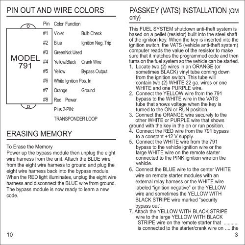
PIN OUT AND WIRE COLORS<br />
Pin<br />
Color Function<br />
PASSKEY (VATS) INSTALLATION (GM<br />
only)<br />
#1<br />
#2<br />
Violet<br />
Blue<br />
Bulb Check<br />
Ignition Neg. Trip<br />
This FUEL SYSTEM shutdown anti-theft system is<br />
based on a pellet (resistor) built into the steel shaft<br />
of the ignition key. When the key is inserted into the<br />
ignition switch, the VATS (vehicle anti-theft system)<br />
#3 GreenNot Used<br />
computer reads the value of the resistor to make<br />
sure that it matches the programmed code and then<br />
MODEL<br />
#4 Yellow/Black Crank Wire<br />
turns on the fuel system so the vehicle can be started.<br />
791<br />
1. Locate two (2) wires in an ORANGE (or<br />
#5 Yellow Bypass Output<br />
sometimes BLACK) vinyl tube coming down<br />
#6 White Ignition Pos. In<br />
from the ignition switch. This tube will<br />
contain two (2) WHITE 22 ga. wires or one<br />
#7 Orange Ground<br />
WHITE and one PURPLE wire.<br />
2. Connect the YELLOW wire from the 791<br />
#8 Red Power<br />
bypass to the WHITE wire in the VATS<br />
tube that shows voltage when the key is<br />
Plus 2-PIN:<br />
TRANSPONDER LOOP<br />
turned to the ON or RUN position.<br />
3. Connect the ORANGE wire securely to the<br />
other WHITE or PURPLE wire that shows<br />
ground with the key in the on or run position.<br />
ERASING MEMORY<br />
4. Connect the RED wire from the 791 bypass<br />
to a constant +12 V supply.<br />
5. Connect the WHITE wire from the 791<br />
To Erase the Memory<br />
Power up the bypass module then unplug the eight<br />
bypass to the vehicle ignition wire or the<br />
large WHITE wire on the remote starter<br />
wire harness from the unit. Attach the BLUE wire<br />
connected to the PINK ignition wire on the<br />
from the eight wire harness to ground and plug the vehicle.<br />
eight wire harness back into the bypass module. 6. Connect the BLUE wire to the center WHITE<br />
When the RED light illuminates, unplug the eight wire wire on remote starter modules with an<br />
harness and disconnect the BLUE wire from ground. external relay harness or the WHITE wire<br />
The bypass module is now ready to learn a new<br />
labeled “ignition negative” or the YELLOW<br />
code.<br />
wire and sometimes the YELLOW WITH<br />
BLACK STRIPE wire marked “security<br />
bypass out”.<br />
7. Attach the YELLOW WITH BLACK STRIPE<br />
wire to the large YELLOW WITH BLACK<br />
STRIPE wire on the remote starter that ...........<br />
is connected to the starter/crank wire on .....the<br />
10 3