UNIVERSAL BYPASS MODULE - Meijer
UNIVERSAL BYPASS MODULE - Meijer
UNIVERSAL BYPASS MODULE - Meijer

You also want an ePaper? Increase the reach of your titles
YUMPU automatically turns print PDFs into web optimized ePapers that Google loves.
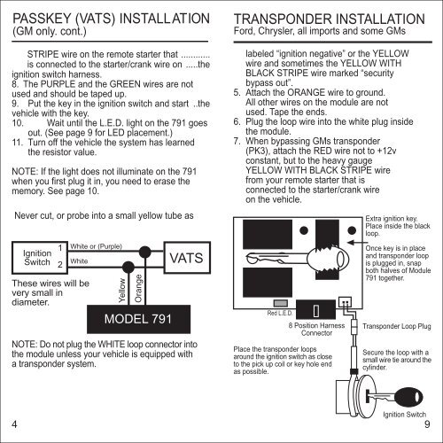
PASSKEY (VATS) INSTALLATION<br />
(GM only. cont.)<br />
STRIPE wire on the remote starter that ............<br />
is connected to the starter/crank wire on .....the<br />
ignition switch harness.<br />
8. The PURPLE and the GREEN wires are not<br />
used and should be taped up.<br />
9. Put the key in the ignition switch and start ..the<br />
vehicle with the key.<br />
10. Wait until the L.E.D. light on the 791 goes<br />
out. (See page 9 for LED placement.)<br />
11. Turn off the vehicle the system has learned<br />
the resistor value.<br />
NOTE: If the light does not illuminate on the 791<br />
when you first plug it in, you need to erase the<br />
memory. See page 10.<br />
Never cut, or probe into a small yellow tube as<br />
Ignition<br />
Switch<br />
1<br />
These wires will be<br />
very small in<br />
diameter.<br />
White or (Purple)<br />
White<br />
VATS<br />
2<br />
Yellow<br />
Orange<br />
MODEL 791<br />
NOTE: Do not plug the WHITE loop connector into<br />
the module unless your vehicle is equipped with<br />
a transponder system.<br />
TRANSPONDER INSTALLATION<br />
Ford, Chrysler, all imports and some GMs<br />
labeled “ignition negative” or the YELLOW<br />
wire and sometimes the YELLOW WITH<br />
BLACK STRIPE wire marked “security<br />
bypass out”.<br />
5. Attach the ORANGE wire to ground.<br />
All other wires on the module are not<br />
used. Tape the ends.<br />
6. Plug the loop wire into the white plug inside<br />
the module.<br />
7. When bypassing GMs transponder<br />
(PK3), attach the RED wire not to +12v<br />
constant, but to the heavy gauge<br />
YELLOW WITH BLACK STRIPE wire<br />
from your remote starter that is<br />
connected to the starter/crank wire<br />
on the vehicle.<br />
Red L.E.D.<br />
8 Position Harness<br />
Connector<br />
Place the transponder loops<br />
around the ignition switch as close<br />
to the pick up coil or key hole end<br />
as possible.<br />
Extra ignition key.<br />
Place inside the black<br />
loop.<br />
Once key is in place<br />
and transponder loop<br />
is plugged in, snap<br />
both halves of Module<br />
791 together.<br />
Transponder Loop Plug<br />
Secure the loop with a<br />
small wire tie around the<br />
cylinder.<br />
Ignition Switch<br />
4 9