PROCOM A/S New Products 2010 - Nkt-rf.ru
PROCOM A/S New Products 2010 - Nkt-rf.ru
PROCOM A/S New Products 2010 - Nkt-rf.ru

You also want an ePaper? Increase the reach of your titles
YUMPU automatically turns print PDFs into web optimized ePapers that Google loves.
<strong>PROCOM</strong> A/S<br />
<strong>New</strong> <strong>Products</strong> <strong>2010</strong><br />
<strong>PROCOM</strong> A/S · Tel. + 45 48 27 84 84 · info@procom.dk · www.procom.dk
<strong>New</strong> <strong>Products</strong> <strong>2010</strong><br />
Base Station & Marine Antennas<br />
CXL 70-5SL/...<br />
CXL 2-5SL/...<br />
CXL 470-870<br />
PCPI xHCP-DP/TETRA<br />
PCPI DCS<br />
PCPI PCS<br />
PCPI DECT<br />
PCPI UMTS<br />
PCPI WIFI<br />
CXL 5700-6<br />
CXL 5200-6LW<br />
YA 2100<br />
Mobile Antennas<br />
FF 4/2/TETRA/FM/GPS-BBMU<br />
GPS-C 4/2/TETRA-S BBMU/...<br />
GPS-C 4/2/TETRA-FM-S BBMU/...<br />
DFSA 4/TETRA-BZ BBMU1<br />
DFSA 4/TETRA-BZ BBMU2<br />
GPS-C TETRA-I<br />
MU 800/900/1800/2100/2600-LX<br />
MU 800/900/1800/2100/2600-MMS<br />
MU 901/1801-LX-SP<br />
Portable Antennas<br />
EFD 345<br />
Filters<br />
BPF 2/3-HX-150<br />
DPF 70/6-XL...<br />
DPBP 70/3333-TETRA-N<br />
BPF 70/33-TETRA-N, BPF 70/33-TETRA-7/16<br />
PRO-DIPX 1000/1550-... HP<br />
DIPX 1000/1550-DC-H/DCK<br />
Combiners<br />
PRO-PHY150-5<br />
PRO-PHY450-3/380-400/SWR<br />
PRO-PHY450-4/380-400/SWR<br />
Combiner components<br />
PRO-DIR 112-200-10 dB<br />
PRO-DIR 112-200-20 dB<br />
RPD 145-470/800-1000-10-N<br />
PRO-IS-130-S1, PRO-IS-130-D1<br />
PRO-IS-380-S1, PRO-IS-380-D1<br />
PRO-PDI-4-TETRA-FME-J<br />
PRO-DIR 0.45-0.8G-10 dB<br />
Multicouplers<br />
MRPS800-2G-FME<br />
MRPS2-GPS-...<br />
PRO-RPS-2-GPS-N<br />
PRO-RPS-4-GPS-N<br />
PRO-RPS-8-GPS-N<br />
<strong>PROCOM</strong> A/S · Tel. + 45 48 27 84 84 · info@procom.dk · www.procom.dk
CXL 70-5SL/...<br />
Sturdy, 5 dBd, Omnidirectional Base Station Antenna for the<br />
TETRA Bands<br />
DESCRIPTION<br />
CXL 70-5SL/… is a 5 dBd, vertically polarized, omnidirectional base<br />
station antenna for the TETRA bands.<br />
The antenna has a bandwidth of 20 MHz.<br />
The antenna is provided with our type "SL" (Slim Line) mast mount,<br />
a multipurpose mounting tube made of non-corrosive aluminium. The<br />
accompanying clamp set and fittings are made of hot-galvanized<br />
steel.<br />
The antenna can be mounted on mast tubes of 33 to 70 mm in outer<br />
diameter.<br />
The antenna element is sealed in a high-quality, conical<br />
glass fibre tube with low wind-load, ensuring undisturbed<br />
pe<strong>rf</strong>ormance in all climates.<br />
To substantially reduce noise caused by atmospherical discharges, all<br />
metal parts in the antenna are DC-grounded. Consequently, the<br />
antenna shows a DC-short across the coaxial cable.<br />
CXL 70-5SL/… is a vibration-proof, slim-line, corrosion-resistant,<br />
modern style base station antenna.<br />
ORDERING DESIGNATIONS<br />
TYPE PRODUCT NO. FREQUENCY<br />
CXL 70-5SL/l 100000326 380 - 400 MHz<br />
CXL 70-5SL/h 100000327 410 - 430 MHz<br />
SPECIFICATIONS<br />
ELECTRICAL<br />
MODEL<br />
ANTENNA TYPE<br />
FREQUENCY<br />
IMPEDANCE<br />
RADIATION<br />
POLARIZATION<br />
GAIN<br />
HALF POWER BEAMWIDTH 15°<br />
BANDWIDTH<br />
CXL 70-5SL/...<br />
High-gain collinear<br />
380 - 400 MHz and 410 - 430 MHz<br />
Nom. 50 Ω<br />
Omnidirectional<br />
Vertical<br />
7 dBi 5 dBd<br />
20 MHz<br />
SWR ≤ 1.6<br />
MAX. POWER<br />
ANTISTATIC<br />
PROTECTION<br />
MECHANICAL<br />
TEMP. RANGE<br />
CONNECTOR<br />
250 W<br />
All metal parts DC-grounded<br />
(Connector shows a DC-short)<br />
-30°C → +70°C<br />
N-female<br />
WIND SURFACE 0.21 m²<br />
WIND LOAD<br />
COLOUR<br />
MATERIALS<br />
TOTAL HEIGHT<br />
WEIGHT<br />
MOUNTING<br />
274 N @ 160 km/h<br />
Marine white<br />
Radome: Polyurethane-coated glass fibre<br />
Procom clamp set: Hot-galvanized steel<br />
Approx. 3.2 m<br />
Approx. 6 kg<br />
On 33 - 70 mm dia. mast tube
TYPICAL GAIN AND SWR CURVES<br />
TYPICAL RADIATION PATTERN (E-PLANE)<br />
SWR<br />
¯ ¯ ¯<br />
Gain dBd<br />
¯¯¯¯¯¯¯¯<br />
f. MHz<br />
TYPICAL RADIATION PATTERN (H-PLANE)<br />
Procom Clamp Set<br />
PLEASE NOTE<br />
When using the CXL 70-5SL/… at windy locations where wind speeds of<br />
more than 150 km/h can be expected, the<br />
antenna must be mounted on the side of the mast and the top section<br />
of the glass fibre tube stabilized with a bracket.<br />
<strong>PROCOM</strong> A/S reserve the right to amend<br />
specifications without prior notice.<br />
18/01/2011
CXL 2-5SL/...<br />
Sturdy, 5 dBd Gain, Base Station Antenna for the 160 MHz<br />
Band<br />
DESCRIPTION<br />
CXL 2-5SL/… is a 5 dBd, vertically polarized, omnidirectional base<br />
station antenna.<br />
The antenna has a bandwidth of 8 MHz. Please specify centre<br />
frequency or duplex TX and RX when ordering.<br />
The antenna is provided with our type "SL" (Slim Line) mast mount,<br />
which is a multipurpose mounting tube made of non-corrosive<br />
aluminium. The accompanying clamp set and fittings are made of hot<br />
galvanized steel.<br />
The antenna can be mounted on mast tubes of 33 to 70 mm in outer<br />
diameter.<br />
In designing this antenna, special emphasis has been laid on<br />
obtaining a large bandwidth both in relation to SWR and gain. The<br />
phasing of the radiating elements is carefully adjusted to yield<br />
maximum gain in the horizontal plane, with the level of the side<br />
lobes reduced to a minimum.<br />
The antenna element is sealed in a high-quality, conical glass fibre<br />
tube with low wind-load, which will ensure pe<strong>rf</strong>ormance undisturbed<br />
in all climates.<br />
To substantially reduce noise caused by atmospherical discharges, all<br />
metal parts in the antenna are DC-grounded. Consequently, the<br />
antenna shows a DC-short across the coaxial cable.<br />
CXL 2-5SL/… is a vibration-proof, lightweight, slim-line, corrosionresistant,<br />
modern style base station antenna.<br />
ORDERING DESIGNATIONS<br />
TYPE<br />
PRODUCT NO.<br />
CXL 2-5SL/... 100000325<br />
SPECIFICATIONS<br />
ELECTRICAL<br />
MODEL<br />
ANTENNA TYPE<br />
FREQUENCY<br />
IMPEDANCE<br />
RADIATION<br />
POLARISATION<br />
GAIN<br />
HALF POWER BEAMWIDTH 18°<br />
BANDWIDTH<br />
CXL 2-5SL/...<br />
High-gain colinear<br />
8 MHz wide frequency segments within the<br />
144 - 175 MHz range.<br />
Please specify centre frequency or duplex<br />
TX and RX<br />
Nom. 50 Ω<br />
Omnidirectional<br />
Vertical<br />
7 dBi 5 dBd<br />
8 MHz<br />
SWR ≤ 1.6<br />
MAX. POWER<br />
ANTISTATIC PROTECTION<br />
MECHANICAL<br />
TEMP. RANGE<br />
CONNECTOR<br />
500 W<br />
All metal parts DC-grounded<br />
(connector shows a DC-short)<br />
-30°C → +70°C<br />
N-female<br />
WIND SURFACE 0.374 m²<br />
WIND LOAD<br />
COLOUR<br />
MATERIALS<br />
TOTAL HEIGHT<br />
WEIGHT<br />
MOUNTING<br />
473 N @ 160 km/h<br />
Marine white<br />
Radome : Polyurethane coated glass fibre<br />
Procom Clamp Set: Hot galvanized steel<br />
Approx. 6.2 m (Dep. on frequency)<br />
Approx. 10 kg<br />
On 33 - 70 mm mast tube<br />
TYPICAL GAIN AND SWR CURVES<br />
SWR<br />
¯ ¯ ¯<br />
Gain dBd<br />
¯¯¯¯¯¯¯¯<br />
f. MHz
Procom Clamp Set<br />
TYPICAL RADIATION PATTERN (E-PLANE)<br />
PLEASE NOTE<br />
When using the CXL 2-5SL/… at windy locations where wind speeds of<br />
more than 150 km/h can be expected, the antenna must be mounted on<br />
the side of the mast and the top section of the glass fibre tube stabilized<br />
with a bracket.<br />
TYPICAL RADIATION PATTERN (H-PLANE)<br />
<strong>PROCOM</strong> A/S reserve the right to amend<br />
specifications without prior notice.<br />
17/03/<strong>2010</strong>
CXL 470-870<br />
0 dBd Broad-Banded Base Station and Marine Antenna for the<br />
470 - 870 MHz<br />
DESCRIPTION<br />
Vertically polarised, omnidirectional base station and marine antenna.<br />
Approximately 0 dBd gain.<br />
Simple mounting using the 1” revolving nut system.<br />
Wide variety of accessory mounting brackets available.<br />
Large bandwidth (470 - 870 MHz) with respect to both SWR and<br />
gain.<br />
The antenna element is sealed in a high-quality, conical glass fibre<br />
tube.<br />
The CXL 470-870 is a vibration-proof, lightweight, slim-line, corrosion<br />
resistant, modern style base station and marine antenna.<br />
The CXL 470-870 is designed specially for both digital and analog<br />
communication systems.<br />
SPECIFICATIONS<br />
ELECTRICAL<br />
MODEL CXL 470-870<br />
ANTENNA TYPE<br />
FREQUENCY<br />
IMPEDANCE<br />
POLARISATION<br />
GAIN<br />
BAND WIDTH<br />
Coaxial, colinear antenna, broad-banded<br />
470 - 870 MHz<br />
Nom. 50 Ω<br />
Vertical<br />
SWR ≤ 2.0<br />
MAX. POWER<br />
MECHANICAL<br />
TEMP. RANGE<br />
CONNECTOR<br />
2 dBi 0 dBd ± 3 dB<br />
≥ 400 MHz<br />
100 W<br />
-30° C → +70° C<br />
N-female<br />
WIND SURFACE Approx. 0.013 m²<br />
WIND LOAD<br />
COLOUR<br />
MATERIALS<br />
TOTAL HEIGHT<br />
DIA. AT TOP END<br />
DIA. AT BOTTOM END<br />
WEIGHT<br />
MOUNTING<br />
Approx. 20 N @ 160 km/h<br />
Marine white<br />
Shroud: Polyurethane coated<br />
glass fibre<br />
Mounting bracket: Chromed brass<br />
Approx. 600 mm<br />
22.5 mm<br />
23 mm<br />
Approx. 350 g<br />
On 1” RG (G1”-11) threaded water pipe or<br />
on optional mounting brackets (see below)
<strong>PROCOM</strong> A/S reserve the right to amend<br />
specifications without prior notice.<br />
03/04/2009
PCPI xHCP-DP/TETRA<br />
Indoor Left or Right Hand Circular Polarized Patch Antennas for<br />
mounting on Wall or Ceiling<br />
DESCRIPTION<br />
Low profile antenna for the 380 - 430 MHz band.<br />
PCPI xHCP-DP/TETRA is a Left or Right Hand Circular Polarized<br />
patch antenna for indoor use.<br />
Circular polarization is chosen to avoid out-of-phase signals.<br />
Reduces flutter considerably.<br />
Specially designed for closed rooms.<br />
Covers approx. 50 MHz with a radiation of approx. 7 dBic.<br />
The antennas are carefully sealed with a discrete cover.<br />
The connector is placed at one side to enable mounting close to a<br />
wall or a ceiling.<br />
Including mounting bracket.<br />
SPECIFICATIONS<br />
ELETRICAL<br />
MODEL<br />
ANTENNA TYPE<br />
FREQUENCY<br />
IMPEDANCE<br />
POLARIZATION<br />
GAIN<br />
PCPI xHCP-DP/TETRA<br />
Left or right hand circular polarized<br />
patch antenna<br />
380 - 430 MHz<br />
Nom. 50 Ω<br />
Circular<br />
Approx. 7 dBic<br />
BANDWIDTH ≥ 50 MHz @ SWR ≤ 2<br />
HALF POWER BEAMWIDTH<br />
SWR<br />
MAX. POWER<br />
MECHANICAL<br />
CONNECTOR<br />
COLOUR<br />
MATERIALS<br />
SIZE (L x W)<br />
HEIGHT<br />
WEIGHT<br />
MOUNTING<br />
Approx. 80° (H- and E-plane)<br />
≤ 1.2 f.res.<br />
100 W<br />
N-female<br />
Marine white<br />
Cover: PS (white)<br />
Chassis: Aluminium<br />
Approx. 340x340 mm<br />
Approx. 60 mm<br />
Approx. 3.5 kg<br />
For mounting on wall or ceiling<br />
ø5 mm (3 holes) (see mounting details)<br />
ORDERING DESIGNATIONS<br />
TYPE NO.<br />
PRODUCT NO.<br />
PCPI RHCP-DP/TETRA 100000331<br />
PCPI LHCP-DP/TETRA 100000341
TYPICAL GAIN AND SWR CURVES<br />
TYPICAL RADIATION PATTERN (E-PLANE)<br />
SWR<br />
¯ ¯ ¯<br />
Gain dBic<br />
¯¯¯¯¯¯¯¯<br />
f. MHz<br />
MOUNTING DETAILS<br />
Mounting plate 200 x 200 mm.<br />
Antenna including cover 340 x 340 mm.<br />
This curve shows the radiation patterns in the<br />
vertical plane.<br />
TYPICAL RADIATION PATTERN (H-PLANE)<br />
This curve shows the radiation patterns in the<br />
horizontal plane (horizontal coverage).<br />
<strong>PROCOM</strong> A/S reserve the right to amend<br />
specifications without prior notice.<br />
12/03/<strong>2010</strong>
PCPI DCS<br />
Indoor Right Hand Circular Polarised Patch Antenna for<br />
mounting on Wall or Ceiling<br />
DESCRIPTION<br />
Low profile antenna for the 1710 - 1880 MHz band.<br />
PCPI DCS is a Right Hand Circular Polarised patch antenna for<br />
indoor use.<br />
Circular polarisation is chosen to avoid out-of-phase signals.<br />
Specially designed for closed rooms.<br />
Covers the DCS frequency range 1710 - 1880 MHz with a radiation of<br />
approx. 5 dBic 3 dBd.<br />
Full size 2 λ circular patch antenna.<br />
The antenna is carefully sealed with a discreet white cover.<br />
The connector is placed at one side to enable mounting close to a<br />
wall or a ceiling.<br />
SPECIFICATIONS<br />
ELECTRICAL<br />
MODEL<br />
ANTENNA TYPE<br />
FREQUENCY<br />
IMPEDANCE<br />
POLARISATION<br />
GAIN<br />
HALF-POWER BEAMWIDTH<br />
SWR<br />
MAX. POWER<br />
MECHANICAL<br />
CONNECTOR<br />
COLOUR<br />
MATERIALS<br />
SIZE (L x W)<br />
HEIGHT<br />
WEIGHT<br />
MOUNTING<br />
PCPI DCS<br />
Right Hand Circular Polarised<br />
patch antenna<br />
1710 - 1880 MHz<br />
Nom. 50 Ω<br />
Circular<br />
Approx. 5 dBic 3 dBd ±2 dB<br />
Approx. 70° (H- and E-plane)<br />
≤ 1.5 f.res.<br />
50 W<br />
N-female<br />
Marine white<br />
Cover: PS<br />
Chassis: Aluminium<br />
Approx. 104 x 104 mm<br />
Approx. 40 mm<br />
Approx. 0.2 kg<br />
For mounting on wall or ceiling<br />
ø4.5 x 10 mm (4 holes)<br />
MOUNTING DETAILS
This curve shows the radiation patterns in<br />
the vertical plane.<br />
This curve shows the radiation patterns<br />
in the horizontal plane (horizontal coverage).<br />
<strong>PROCOM</strong> A/S reserve the right to amend<br />
specifications without prior notice.<br />
02/03/2009
PCPI PCS<br />
Indoor Right Hand Circular Polarised Patch Antenna for<br />
mounting on Wall or Ceiling<br />
DESCRIPTION<br />
Low profile antenna for the 1850 - 1990 MHz band.<br />
PCPI PCS is a Right Hand Circular Polarised patch antenna for indoor<br />
use.<br />
Circular polarisation is chosen to avoid out-of-phase signals.<br />
Specially designed for closed rooms.<br />
Covers the PCS frequency range 1850 - 1990 MHz with a radiation of<br />
approx. 5 dBic 3 dBd.<br />
Full size 2 λ circular patch antenna.<br />
The antenna is carefully sealed with a discreet white cover.<br />
The connector is placed at one side to enable mounting close to a<br />
wall or a ceiling.<br />
SPECIFICATIONS<br />
ELECTRICAL<br />
MODEL<br />
ANTENNA TYPE<br />
FREQUENCY<br />
IMPEDANCE<br />
POLARISATION<br />
GAIN<br />
HALF-POWER BEAMWIDTH<br />
SWR<br />
MAX. POWER<br />
MECHANICAL<br />
CONNECTOR<br />
COLOUR<br />
MATERIALS<br />
SIZE (L x W)<br />
HEIGHT<br />
WEIGHT<br />
MOUNTING<br />
PCPI PCS<br />
Right Hand Circular Polarised<br />
patch antenna<br />
1850 - 1990 MHz<br />
Nom. 50 Ω<br />
Circular<br />
Approx. 5 dBic 3 dBd ±2 dB<br />
Approx. 70° (H- and E-plane)<br />
≤ 1.5 f.res.<br />
50 W<br />
N-female<br />
Marine white<br />
Cover: PS<br />
Chassis: Aluminium<br />
Approx. 104 x 104 mm<br />
Approx. 40 mm<br />
Approx. 0.2 kg<br />
For mounting on wall or ceiling<br />
ø4.5 x 10 mm (4 holes)<br />
MOUNTING DETAILS
This curve shows the radiation patterns in<br />
the vertical plane.<br />
This curve shows the radiation patterns<br />
in the horizontal plane (horizontal coverage).<br />
<strong>PROCOM</strong> A/S reserve the right to amend<br />
specifications without prior notice.<br />
02/03/2009
PCPI DECT<br />
Indoor Right Hand Circular Polarised Patch Antenna for<br />
mounting on Wall or Ceiling<br />
DESCRIPTION<br />
Low profile antenna for the 1880 - 1900 MHz band.<br />
PCPI DECT is a Right Hand Circular Polarised patch antenna for<br />
indoor use.<br />
Circular polarisation is chosen to avoid out-of-phase signals.<br />
Specially designed for closed rooms.<br />
Covers the Dect frequency range 1880 - 1900 MHz with a radiation<br />
of approx. 5 dBic 3 dBd.<br />
Full size 2 λ circular patch antenna.<br />
The antenna is carefully sealed with a discreet white cover.<br />
The connector is placed at one side to enable mounting close to a<br />
wall or a ceiling.<br />
SPECIFICATIONS<br />
ELECTRICAL<br />
MODEL<br />
ANTENNA TYPE<br />
FREQUENCY<br />
IMPEDANCE<br />
POLARISATION<br />
GAIN<br />
HALF-POWER BEAMWIDTH<br />
SWR<br />
MAX. POWER<br />
MECHANICAL<br />
CONNECTOR<br />
COLOUR<br />
MATERIALS<br />
SIZE (L x W)<br />
HEIGHT<br />
WEIGHT<br />
MOUNTING<br />
PCPI DECT<br />
Right Hand Circular Polarised<br />
patch antenna<br />
1880 - 1900 MHz<br />
Nom. 50 Ω<br />
Circular<br />
Approx. 5 dBic 3 dBd ±2 dB<br />
Approx. 70° (H- and E-plane)<br />
≤ 1.5 f.res.<br />
50 W<br />
N-female<br />
Marine white<br />
Cover: PS<br />
Chassis: Aluminium<br />
Approx. 104 x 104 mm<br />
Approx. 40 mm<br />
Approx. 0.2 kg<br />
For mounting on wall or ceiling<br />
ø4.5 x 10 mm (4 holes)<br />
MOUNTING DETAILS
This curve shows the radiation patterns in<br />
the vertical plane.<br />
This curve shows the radiation patterns<br />
in the horizontal plane (horizontal coverage).<br />
<strong>PROCOM</strong> A/S reserve the right to amend<br />
specifications without prior notice.<br />
02/03/2009
PCPI UMTS<br />
Indoor Right Hand Circular Polarised Patch Antenna for<br />
mounting on Wall or Ceiling<br />
DESCRIPTION<br />
Low profile antenna for the 1910 - 2200 MHz band.<br />
PCPI UMTS is a Right Hand Circular Polarised patch antenna for<br />
indoor use.<br />
Circular polarisation is chosen to avoid out-of-phase signals.<br />
Specially designed for closed rooms.<br />
Covers the UMTS frequency range 1910 - 2200 MHz with a radiation<br />
of approx. 5 dBic 3 dBd.<br />
Full size 2 λ circular patch antenna.<br />
The antenna is carefully sealed with a discreet white cover.<br />
The connector is placed at one side to enable mounting close to a<br />
wall or a ceiling.<br />
SPECIFICATIONS<br />
ELECTRICAL<br />
MODEL<br />
ANTENNA TYPE<br />
FREQUENCY<br />
IMPEDANCE<br />
POLARISATION<br />
GAIN<br />
HALF-POWER BEAMWIDTH<br />
SWR<br />
MAX. POWER<br />
MECHANICAL<br />
CONNECTOR<br />
COLOUR<br />
MATERIALS<br />
SIZE (L x W)<br />
HEIGHT<br />
WEIGHT<br />
MOUNTING<br />
PCPI UMTS<br />
Right Hand Circular Polarised<br />
patch antenna<br />
1910 - 2200 MHz<br />
Nom. 50 Ω<br />
Circular<br />
Approx. 5 dBic 3 dBd ±2 dB<br />
Approx. 70° (H- and E-plane)<br />
≤ 1.5 f.res.<br />
50 W<br />
N-female<br />
Marine white<br />
Cover: PS<br />
Chassis: Aluminium<br />
Approx. 104x104 mm<br />
Approx. 40 mm<br />
Approx. 0.2 kg<br />
For mounting on wall or ceiling<br />
ø4.5x10 mm (4 holes)<br />
MOUNTING DETAILS
This curve shows the radiation patterns in<br />
the vertical plane.<br />
This curve shows the radiation patterns<br />
in the horizontal plane (horizontal coverage).<br />
<strong>PROCOM</strong> A/S reserve the right to amend<br />
specifications without prior notice.<br />
02/03/2009
PCPI WIFI<br />
Indoor Right Hand Circular Polarized Patch Antenna for<br />
mounting on Wall or Ceiling<br />
DESCRIPTION<br />
Low profile antenna for the 2400 - 2500 MHz band.<br />
PCPI WIFI is a Right Hand Circular Polarized patch antenna for<br />
indoor use.<br />
Circular polarization is chosen to avoid out-of-phase signals.<br />
Specially designed for closed rooms.<br />
The antenna is carefully sealed with a discrete white cover.<br />
The connector is placed at one side to enable mounting close to a<br />
wall or a ceiling.<br />
SPECIFICATIONS<br />
ELECTRICAL<br />
MODEL<br />
ANTENNA TYPE<br />
FREQUENCY<br />
IMPEDANCE<br />
POLARIZATION<br />
GAIN<br />
HALF-POWER BEAMWIDTH<br />
SWR ≤ 2<br />
MAX. POWER<br />
MECHANICAL<br />
CONNECTOR<br />
COLOUR<br />
MATERIALS<br />
SIZE (L x W)<br />
HEIGHT<br />
WEIGHT<br />
MOUNTING<br />
PCPI WIFI<br />
Right Hand Circular Polarized<br />
patch antenna<br />
WIFI: 2400 - 2500 MHz<br />
Nom. 50 Ω<br />
Circular<br />
Approx. 5 dBic 3 dBd ±2 dB<br />
Approx. 70° (H- and E-plane)<br />
50 W<br />
N-female<br />
Marine white<br />
Cover: PS<br />
Chassis: Aluminium<br />
Approx. 104 x 104 mm<br />
Approx. 40 mm<br />
Approx. 0.2 kg<br />
For mounting on wall or ceiling<br />
ø4.5 x 10 mm (4 holes)<br />
MOUNTING DETAILS<br />
(Dimensions excl. cover)<br />
ORDERING DESIGNATIONS<br />
TYPE<br />
PRODUCT NO.<br />
PCPI WIFI 100000363<br />
TYPICAL GAIN AND SWR CURVES<br />
SWR _ _ _ ______ Gain dBd<br />
f. MHz
TYPICAL RADIATION PATTEN (E-PLANE)<br />
This curve shows the radiation patterns in<br />
the vertical plane.<br />
TYPICAL RADIATION PATTEN (H-PLANE)<br />
This curve shows the radiation patterns<br />
in the horizontal plane (horizontal coverage).<br />
<strong>PROCOM</strong> A/S reserve the right to amend<br />
specifications without prior notice.<br />
19/08/<strong>2010</strong>
CXL 5700-6<br />
6 dBd Omnidirectional Base Station and Marine Antenna for<br />
the 5700 MHz Band<br />
ORDERING DESIGNATIONS<br />
TYPE<br />
PRODUCT NO.<br />
CXL 5700-6 100000291<br />
DESCRIPTION<br />
Vertically polarized, omnidirectional base station and marine antenna.<br />
Approximately 6 dBd gain.<br />
Wide variety of accessory mounting brackets available.<br />
Highly suitable for duplex operation with large spacing between the<br />
TX and the RX frequencies.<br />
The antenna element is sealed in a high-quality, conical glass fibre<br />
tube.<br />
The CXL 5700-6 is a vibration-proof, lightweight, slim-line, corrosion<br />
resistant, modern style base station and marine antenna.<br />
SPECIFICATIONS<br />
ELECTRICAL<br />
MODEL CXL 5700-6<br />
ANTENNA TYPE<br />
FREQUENCY<br />
IMPEDANCE<br />
POLARIZATION<br />
GAIN<br />
Coaxial, colinear antenna, broad-banded<br />
with 3 - 5° electrical downtilt<br />
5450 - 5750 MHz<br />
Nom. 50 Ω<br />
Vertical<br />
8 dBi 6 dBd<br />
BANDWIDTH ≥ 300 MHz @ SWR ≤ 2.0<br />
SWR ≤ 2.0<br />
MAX. POWER<br />
ANTISTATIC PROTECTION<br />
MECHANICAL<br />
TEMP. RANGE<br />
CONNECTOR<br />
100 W<br />
All metal parts DC-grounded<br />
(Connector shows a DC-short)<br />
-30°C → +70°C<br />
N-female<br />
WIND SURFACE Approx. 0.007 m²<br />
WIND LOAD<br />
COLOUR<br />
MATERIALS<br />
TOTAL HEIGHT<br />
DIA. AT TOP END<br />
DIA. AT BOTTOM END<br />
WEIGHT<br />
MOUNTING<br />
Approx. 10 N @ 160 km/h<br />
Marine white<br />
Shroud: Polyurethane-coated glass fibre<br />
Mounting bracket: Chromed brass<br />
Approx. 378 mm<br />
13 mm<br />
16 mm<br />
Approx. 200 g<br />
On 1” RG (G1”-11) threaded water pipe or<br />
on optional mounting brackets<br />
TYPICAL GAIN AND SWR CURVES<br />
SWR<br />
¯ ¯ ¯ ¯<br />
Gain dBd<br />
¯¯¯¯¯¯¯¯¯
ACCESSORIES<br />
(to be ordered separately)<br />
TYPICAL RADIATION PATTERN (E-PLANE)<br />
TYPICAL RADIATION PATTERN (H-PLANE)<br />
<strong>PROCOM</strong> A/S reserve the right to amend<br />
specifications without prior notice.<br />
09/03/<strong>2010</strong>
CXL 5200-6LW<br />
6 dBd Omnidirectional Base Station and Marine Antenna for<br />
the 5200 MHz Band<br />
ORDERING DESIGNATIONS<br />
TYPE<br />
PRODUCT NO.<br />
CXL 5200-6LW 100000296<br />
DESCRIPTION<br />
Vertically polarized, omnidirectional base station and marine antenna.<br />
Approximately 6 dBd gain.<br />
Highly suitable for duplex operation with large spacing between the<br />
TX and the RX frequencies.<br />
The antenna element is sealed in a high-quality, conical glass fibre<br />
tube.<br />
All metal parts in the antenna are DC-grounded to reduce the noise<br />
caused by atmospherical discharge. Consequently, the antenna<br />
shows a DC-short across the coaxial cable.<br />
The CXL 5200-6LW is a vibration-proof, lightweight, slim-line,<br />
corrosion resistant, modern style base station and marine antenna.<br />
SPECIFICATIONS<br />
ELECTRICAL<br />
MODEL<br />
ANTENNA TYPE<br />
FREQUENCY<br />
IMPEDANCE<br />
POLARIZATION<br />
GAIN<br />
CXL 5200-6LW<br />
Coaxial, colinear antenna, broad-banded<br />
5150 - 5250 MHz<br />
Nom. 50 Ω<br />
Vertical<br />
8 dBi 6 dBd<br />
BANDWIDTH ≥ 100 MHz @ SWR ≤ 1.5<br />
SWR ≤ 1.5<br />
MAX. POWER<br />
ANTISTATIC PROTECTION<br />
MECHANICAL<br />
TEMP. RANGE<br />
CONNECTOR<br />
35 W<br />
All metal parts DC-grounded<br />
(Connector shows a DC-short)<br />
-30°C → +70°C<br />
N-female<br />
WIND SURFACE Approx. 0.009 m²<br />
WIND LOAD<br />
COLOUR<br />
MATERIALS<br />
TOTAL HEIGHT<br />
DIA. AT TOP END<br />
DIA. AT BOTTOM END<br />
WEIGHT<br />
MOUNTING<br />
Approx. 12 N @ 160 km/h<br />
Marine white<br />
Shroud: Polyurethane-coated glass fibre<br />
Mounting bracket: Chromed brass<br />
Approx. 530 mm<br />
13 mm<br />
16 mm<br />
Approx. 520 g<br />
On 16 to 54 mm dia. mast tube
MULTI-PURPOSE MOUNTING BRACKET<br />
TYPICAL RADIATION PATTERN (E-PLANE)<br />
TYPICAL RADIATION PATTERN (H-PLANE)<br />
TYPICAL GAIN AND SWR CURVE<br />
SWR<br />
¯ ¯ ¯ ¯<br />
Gain dBd<br />
¯¯¯¯¯¯¯¯<br />
<strong>PROCOM</strong> A/S reserve the right to amend<br />
specifications without prior notice.<br />
25/03/<strong>2010</strong><br />
f. MHz
YA 2100<br />
Low-Cost Directional Antenna for Networks in the 2100 MHz<br />
Band<br />
DESCRIPTION<br />
Low-cost and low-weight directional antenna.<br />
Approx. 10 dBi gain.<br />
“Built-in” mounting bracket.<br />
Supplied with fittings and bolts for mounting on 30 - 50 mm diameter<br />
mast tube.<br />
TYPICAL SWR AND GAIN CURVES<br />
SWR<br />
¯ ¯ ¯<br />
Gain dBi<br />
¯¯¯¯¯¯¯<br />
f. MHz<br />
With the YA 2100 you will experience a significant improvement of the<br />
quality of your communication on the 2100 MHz networks.<br />
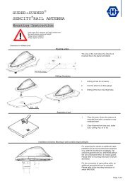
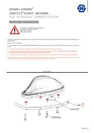
INSTALLATION STEPS<br />
Mount the antenna on a 30-50 mm diameter mast tube using the<br />
accompanying fittings and bolts (see illustration on the other page).<br />
The antenna is to be oriented as indicated on the connection box of<br />
the antenna.<br />
ORDERING DESIGNATIONS<br />
TYPE<br />
PRODUCT NO.<br />
YA 2100 130001553<br />
SPECIFICATIONS<br />
ELECTRICAL<br />
MODEL YA 2100<br />
ANTENNA TYPE<br />
FREQUENCY<br />
IMPEDANCE<br />
POLARIZATION<br />
GAIN<br />
FRONT-TO-BACK-RATIO<br />
HALF-POWER BEAMWIDTH<br />
BANDWIDTH<br />
9-element Yagi-antenna<br />
2000 – 2200 MHz<br />
Nom. 50 Ω<br />
Linear<br />
(vertical or horizontal dep. on orientation)<br />
10 dBi 8 dBd<br />
≥ 10 dB<br />
Approx. 50° (H-plane)<br />
200 MHz<br />
SWR ≤ 1.8<br />
MAX. POWER<br />
MECHANICAL<br />
MATERIALS<br />
COLOUR<br />
TOTAL LENGTH<br />
MAX. ELEMENT HEIGHT<br />
WEIGHT<br />
CONNECTORS<br />
MOUNTING<br />
25 W<br />
Antenna: Gold aludine, Aluminium<br />
Fittings: Stainless steel<br />
Aludine “gold”<br />
570 mm<br />
100 mm<br />
400 g (incl. bolts)<br />
FME-connector<br />
(cable to be ordered separately)<br />
On 30 – 50 mm dia. mast tube<br />
Direct the antenna towards the nearest base station for the 2100<br />
MHz network in question. The correct direction may be determined<br />
using the field strength indicator telephone:<br />
Mount the antenna on your mast.<br />
Rotate the antenna (in the horizontal plane) while observing the field<br />
strength indicator.<br />
Choose the direction in which the highest field strength level is<br />
observed and fasten the antenna.
TYPICAL RADIATION PATTERN (E-PLANE)<br />
TYPICAL RADIATION PATTERN (H-PLANE)<br />
<strong>PROCOM</strong> A/S reserve the right to amend<br />
specifications without prior notice.<br />
16/03/<strong>2010</strong>
FF 4/2/TETRA/FM/GPS-BBMU<br />
Disguise Antenna for Ford Focus<br />
DESCRIPTION<br />
ORDERING DESIGNATIONS<br />
TYPE<br />
PRODUCT NO.<br />
FF 4/2/TETRA/FM/GPS-BBMU 132000107<br />
4-Band mobile antenna with 4 m, 2 m, 70 cm and FM bands.<br />
GPS-antenna for fixed installations.<br />
External antenna whip mounted on the FORD GPS mount.<br />
Full hemispherical coverage.<br />
Built-in high-gain, low-noise amplifier.<br />
Right-Hand Circular Polarization (RHCP).<br />
DC supply via RF-connector.<br />
Polyethylene-covered flexible whip.<br />
Easily removable whip for car wash.<br />
Matching unit (BBMU) included.<br />
SPECIFICATIONS FOR WHIP<br />
ELECTRICAL<br />
MODEL<br />
ANTENNA TYPE<br />
FREQUENCY<br />
FF 4/2/TETRA/FM/GPS-BBMU<br />
Colinear mobile whip antenna<br />
4 m: 74.2 - 87.5 MHz<br />
2 m: 167.5 - 174 MHz<br />
70 cm: 380 - 400 MHz<br />
FM band: 93 - 108 MHz (Limited in 88 - 93 MHz)<br />
SWR 74.2 - 77.7 and 84 - 87.5 MHz: < 2.5<br />
167.5 - 169.5 and 172 - 174 MHz: < 2.0<br />
380 - 400 MHz: < 2.0<br />
IMPEDANCE<br />
POLARIZATION<br />
GAIN<br />
MAX. POWER<br />
MECHANICAL<br />
MATERIALS<br />
COLOUR<br />
HEIGHT<br />
WEIGHT<br />
MOUNTING<br />
Nom. 50 Ω<br />
Vertical<br />
4 m: Approx. -10/-15 dB<br />
2 m: Approx. -10/-15 dB<br />
70 cm: Approx. -5/-10 dB (acc. to EIA RS-329-1)<br />
25 W<br />
Glass fibre whip with copper wire winding,<br />
polyethylene-covered.<br />
Black-chromed brass<br />
Black<br />
660 mm<br />
102 g<br />
On standard FORD GPS mount<br />
<strong>PROCOM</strong> A/S reserve the right to amend<br />
specifications without prior notice.<br />
03/01/2011
GPS-C 4/2/TETRA-S BBMU/...<br />
Colinear Mobile Antenna for the 4m, 2m and TETRA Bands<br />
DESCRIPTION<br />
GPS-antenna for fixed installations.<br />
External antenna whip mounted on the GPS-Combi mount.<br />
Full hemispherical coverage.<br />
Built-in high-gain, low-noise amplifier.<br />
Right-Hand Circular Polarization (RHCP).<br />
5 V supply voltage (3 V respectively 12 V available on request).<br />
DC supply via RF-connector.<br />
Polyethylene-covered flexible whip.<br />
Easily removable whip for car wash.<br />
Matching unit (BBMU) included.<br />
SPECIFICATIONS FOR WHIP<br />
ELECTRICAL<br />
MODEL<br />
ANTENNA TYPE<br />
FREQUENCY<br />
GPS-C 4/2/TETRA-S BBMU/...<br />
Colinear mobile whip antenna<br />
4 m: 74.2 - 87.5 MHz<br />
2 m: 167.5 - 174 MHz<br />
70 cm: 380 - 400 MHz<br />
SWR 74.2 - 77.7 and 84 - 87.5 MHz: ≤ 2.5<br />
167.5 - 169.5 and 172 - 174 MHz: ≤ 2.0<br />
380 - 400 MHz: ≤ 2.0<br />
IMPEDANCE<br />
POLARIZATION<br />
GAIN<br />
MAX. POWER<br />
MECHANICAL<br />
MATERIALS<br />
COLOUR<br />
HEIGHT<br />
WEIGHT<br />
MOUNTING<br />
Nom. 50 Ω<br />
Vertical<br />
4 m: ca. -2 dB<br />
2 m: ca. -4 dB<br />
70 cm: ca. 2 dB (acc. to EIA RS-329-1)<br />
25 W<br />
Whip: Glass fibre whip with copper wire winding,<br />
polyethylene-covered<br />
Black-chromed brass<br />
Spring: Black-chromed stainless steel<br />
Black<br />
670 mm<br />
60 g<br />
On the GPS-Combi mount<br />
ORDERING DESIGNATIONS<br />
TYPE PRODUCT NO. ROOF THICKNESS<br />
GPS-C 4/2/TETRA-S BBMU 132 000 084 Max. 2.0 mm<br />
GPS-C 4/2/TETRA-S BBMU/7mm 132 000 096 3.5 - 7.5 mm<br />
SPECIFICATIONS FOR GPS-COMBI MOUNT<br />
ELECTRICAL General specifications<br />
MODEL<br />
ANTENNA TYPE<br />
FREQUENCY<br />
IMPEDANCE<br />
POLARIZATION<br />
COVERAGE<br />
GAIN<br />
CROSS-POLARIZATION<br />
ATT.<br />
Built-in amplifier<br />
GAIN<br />
NOISE FIGURE<br />
P 1 dB<br />
SELECTIVITY<br />
GPS-COMBI MOUNT<br />
Active patch antenna<br />
1575 MHz<br />
Nom. 50 Ω<br />
SWR (output) ≤ 2.0<br />
SUPPLY VOLTAGE<br />
CURRENT<br />
CONSUMPTION<br />
Circular right-hand<br />
Hemispherical<br />
28 dBic in axial direction (typ.)<br />
> 10 dB (typ.)<br />
> 30 dB (typ.)<br />
< 1 dB (typ.)<br />
Approx. +7 dBm<br />
> 45 dB down at ± 45 MHz<br />
5 ± 0.5 VDC (3 V resp. 12 V on request)<br />
Approx. 25 mA<br />
MECHANICAL (only for the GPS-part)<br />
MATERIALS<br />
ANTENNA COLOUR<br />
TEMP. RANGE<br />
Cu-nite brass. Stainless steel<br />
Reinforced thermoplastic<br />
Black<br />
-35° C →+75° C<br />
CONNECTOR FME (male for GPS) +<br />
FME (female for mobile antenna)<br />
RECOMMENDED<br />
INSTALL. TORQUE<br />
DIMENSIONS (H x L)<br />
ROOF THICKNESS<br />
WEIGHT<br />
MOUNTING<br />
4 ± 0.5 Nm<br />
Approx. 30 x 89 mm<br />
Max. 2.0 mm or<br />
3.5 - 7.5 mm<br />
Approx. 114 g<br />
ø18 mm dia. hole (For roof thickness 2.5 mm<br />
mounting hole should be ø18.5 mm dia.)<br />
For roof thickness 3.5 mm up to 7.5 mm<br />
mounting hole should be ø19 mm dia.<br />
Tools for mounting included
MOUNTING INSTRUCTIONS<br />
TYPICAL RESPONSE CURVES<br />
Do not use sealer on <strong>ru</strong>bber gasket or other places.<br />
CABLE MOUNTING<br />
<strong>PROCOM</strong> A/S reserve the right to amend<br />
specifications without prior notice.<br />
30/06/<strong>2010</strong>
GPS-C 4/2/TETRA-FM-S<br />
BBMU/...<br />
Colinear Mobile Antenna for the 4m, 2m, FM and TETRA<br />
Bands<br />
DESCRIPTION<br />
GPS-antenna for fixed installations.<br />
External antenna whip mounted on the GPS-Combi mount.<br />
Full hemispherical coverage.<br />
Built-in high-gain, low-noise amplifier.<br />
Right-Hand Circular Polarization (RHCP).<br />
5 V supply voltage (3 V respectively 12 V available on request).<br />
DC supply via RF-connector.<br />
Polyethylene-covered flexible whip.<br />
Easily removable whip for car wash.<br />
Matching unit (BBMU) included.<br />
SPECIFICATIONS FOR WHIP<br />
ELECTRICAL<br />
MODEL<br />
ANTENNA TYPE<br />
FREQUENCY<br />
GPS-C 4/2/TETRA-FM-S BBMU/...<br />
Colinear mobile whip antenna<br />
4 m: 74.2 - 87.5 MHz<br />
2 m: 167.5 - 174 MHz<br />
70 cm: 380 - 400 MHz<br />
FM band: 88 - 108 MHz<br />
SWR 74.2 - 77.7 and 84 - 87.5 MHz: < 2.5<br />
167.5 - 169.5 and 172 - 174 MHz: < 2.0<br />
380 - 400 MHz: < 2.0<br />
IMPEDANCE<br />
POLARIZATION<br />
GAIN<br />
MAX. POWER<br />
MECHANICAL<br />
MATERIALS<br />
COLOUR<br />
HEIGHT<br />
WEIGHT<br />
MOUNTING<br />
Nom. 50 Ω<br />
Vertical<br />
4 m: ca. -3 dB<br />
2 m: ca. -4 dB<br />
70 cm: ca. 2 dB (acc. to EIA RS-329-1)<br />
25 W<br />
Whip: Glass fibre whip with copper wire winding,<br />
polyethylene-covered. Black-chromed brass<br />
Spring: Black-chromed stainless steel<br />
Black<br />
670 mm<br />
60 g<br />
On the GPS-Combi mount<br />
ORDERING DESIGNATIONS<br />
TYPE PRODUCT NO. ROOF THICKNESS<br />
GPS-C 4/2/TETRA-FM-S BBMU 132 000 090 Max. 2.0 mm<br />
GPS-C 4/2/TETRA-FM-S BBMU/7mm 132 000 110 3.5 - 7.5 mm<br />
SPECIFICATIONS FOR GPS-COMBI MOUNT<br />
ELECTRICAL General specifications<br />
MODEL<br />
ANTENNA TYPE<br />
FREQUENCY<br />
IMPEDANCE<br />
POLARIZATION<br />
COVERAGE<br />
GAIN<br />
CROSS-POLARIZATION<br />
ATT.<br />
Built-in amplifier<br />
GAIN<br />
NOISE FIGURE<br />
P 1 dB<br />
SELECTIVITY<br />
GPS-COMBI MOUNT<br />
Active patch antenna<br />
1575 MHz<br />
Nom. 50 Ω<br />
SWR (output) ≤ 2.0<br />
SUPPLY VOLTAGE<br />
CURRENT CONSUMPTION<br />
Circular right-hand<br />
Hemispherical<br />
28 dBic in axial direction (typ.)<br />
> 10 dB (typ.)<br />
> 30 dB (typ.)<br />
< 1 dB (typ.)<br />
MECHANICAL (only for the GPS-part)<br />
MATERIALS<br />
ANTENNA COLOUR<br />
TEMP. RANGE<br />
Approx. +7 dBm<br />
> 45 dB down at ± 45 MHz<br />
5 ± 0.5 VDC (3 V resp. 12 V on request)<br />
Approx. 25 mA<br />
Cu-nite brass. Stainless steel<br />
Reinforced thermoplastic<br />
Black<br />
-35° C →+75° C<br />
CONNECTOR FME (male for GPS) +<br />
FME (female for mobile antenna)<br />
RECOMMENDED<br />
INSTALL. TORQUE<br />
DIMENSIONS (H x L)<br />
ROOF THICKNESS<br />
WEIGHT<br />
MOUNTING<br />
4 ± 0.5 Nm<br />
Approx. 30 x 89 mm<br />
Max. 2.0 mm or<br />
3.5 - 7.5 mm<br />
Approx. 114 g<br />
ø18 mm dia. hole (For roof thickness 2.5 mm<br />
mounting hole should be ø18.5 mm dia.)<br />
For roof thickness 3.5 mm up to 7.5 mm<br />
mounting hole should be ø19 mm dia.<br />
Tools for mounting included
MOUNTING INSTRUCTIONS<br />
TYPICAL RESPONSE CURVES<br />
Do not use sealer on <strong>ru</strong>bber gasket or other places.<br />
CABLE MOUNTING<br />
<strong>PROCOM</strong> A/S reserve the right to amend<br />
specifications without prior notice.<br />
30/06/<strong>2010</strong><br />
PLEASE NOTE:<br />
The cable between the GPS-C Mount and BBMU box must not be extended.
DFSA 4/TETRA-BZ BBMU1<br />
Dual-frequency shortened Mobile Antenna for the 4 m and<br />
TETRA Bands<br />
ORDERING DESIGNATIONS<br />
TYPE<br />
PRODUCT NO.<br />
DFSA 4/TETRA-BZ BBMU1 130 001 586<br />
DESCRIPTION<br />
External antenna whip mounted on the BZ-mount.<br />
Stainless steel BZ-mount with ball-joint and wing screw<br />
whip-fastening system.<br />
Polyethylene-covered flexible whip.<br />
Dual-frequency mobile antenna for the 4 m and TETRA bands.<br />
Easily removable whip for car wash.<br />
BZP0.1-mount permanently attached 100 mm cable terminated with<br />
FME-connector.<br />
Matching unit (BBMU) with TNC female output connector included.<br />
SPECIFICATIONS<br />
ELECTRICAL<br />
MODEL<br />
ANTENNA TYPE<br />
FREQUENCY<br />
IMPEDANCE<br />
POLARIZATION<br />
GAIN<br />
SWR<br />
MAX. POWER<br />
MECHANICAL<br />
MATERIALS<br />
RECOMMENDED<br />
INSTALLATION<br />
TORQUE<br />
COLOUR<br />
HEIGHT<br />
WEIGHT<br />
DIMENSIONS<br />
MOUNTING<br />
ROOF<br />
THICKNESS<br />
DFSA 4/TETRA-BZ BBMU1<br />
Dual-frequency shortened mobile antenna<br />
4 m: 73 - 80 MHz<br />
TETRA: 380 - 410 MHz<br />
Nom. 50 Ω<br />
Vertical<br />
4 m: approx. -6 dB ±2 dB<br />
TETRA: approx. 1 dB<br />
(acc. to EIA RS-329-1)<br />
≤ 1.9 in both bands<br />
25 W<br />
Whip:<br />
Glass fibre whip with copper wire winding, polyethylenecovered<br />
Black-chromed brass<br />
Mount:<br />
Black-chromed brass<br />
Weather- and shockproof plastics<br />
Stainless steel<br />
7.5 ± 1 Nm<br />
Black<br />
Approx. 670 mm<br />
Approx. 150 g<br />
Antenna: approx. 670 mm<br />
Connecting cable: 100 mm RG 58 with FME-conn.<br />
Matching unit: 50 x 50 x 20 mm<br />
ø21 mm dia. hole<br />
(For roof thicknesses 2 mm up to 7.5 mm<br />
mounting hole should be ø22 mm dia.)<br />
Max. 2.0 mm<br />
(Models up to 7.5 mm on request)<br />
BZP0.1-MOUNT WITH 0.1 m FME RG 58
INSTALLATION<br />
This antenna is supplied with type BZ-mount. The whip is fastened to<br />
the mount by means of our standard ball-joint and wing screw system.<br />
The adjustable ball-joint ensures that the whip can always be mounted<br />
in a vertical position independent of the angle of the installation spot.<br />
The BZ-mount is particularly well suited for mounting on car roofs<br />
because of its ability to be installed exclusively with access from the<br />
outside. The BZ-mount for roof thicknesses from 2 mm to<br />
7.5 mm must be mounted from the inside. However, the antenna can be<br />
installed anywhere on the car as the BZ-mount is equally well suited for<br />
mounting on e.g. t<strong>ru</strong>nk or wing.<br />
1. INSTALLATION DIMENSIONS<br />
PLEASE NOTE<br />
As standard the antenna is provided with wing screw. However, the<br />
wing screw may be replaced by the less obt<strong>ru</strong>sive hat screw (with key),<br />
which also gives an improved protection against theft. To order the<br />
antenna with hat screw, please add a “K” to the antenna designation.<br />
<strong>PROCOM</strong> A/S reserve the right to amend<br />
specifications without prior notice.<br />
30/07/<strong>2010</strong><br />
2. INSTALLATION STEPS
DFSA 4/TETRA-BZ BBMU2<br />
Dual-frequency shortened Mobile Antenna for the 4 m and<br />
TETRA Bands<br />
DESCRIPTION<br />
External antenna whip mounted on the BZ-mount.<br />
Stainless steel BZ-mount with ball-joint and wing screw<br />
whip-fastening system.<br />
Polyethylene-covered flexible whip.<br />
Dual-frequency mobile antenna for the 4 m and TETRA bands.<br />
Easily removable whip for car wash.<br />
BZP0.1-mount permanently attached 100 mm cable terminated with<br />
FME-connector.<br />
Matching unit (BBMU) with 2 TNC female output connectors included.<br />
Separate outputs for the 4 m and TETRA bands<br />
ORDERING DESIGNATIONS<br />
TYPE<br />
PRODUCT NO.<br />
DFSA 4/TETRA-BZ BBMU2 130 001 587<br />
SPECIFICATIONS<br />
ELECTRICAL<br />
MODEL<br />
ANTENNA TYPE<br />
FREQUENCY<br />
IMPEDANCE<br />
POLARIZATION<br />
GAIN<br />
SWR<br />
MAX. POWER<br />
MECHANICAL<br />
MATERIALS<br />
RECOMMENDED<br />
INSTALLATION<br />
TORQUE<br />
COLOUR<br />
HEIGHT<br />
WEIGHT<br />
DIMENSIONS<br />
MOUNTING<br />
ROOF<br />
THICKNESS<br />
DFSA 4/TETRA-BZ BBMU2<br />
Dual-frequency shortened mobile antenna<br />
4 m: 73 - 80 MHz<br />
TETRA: 380 - 410 MHz<br />
Nom. 50 Ω<br />
Vertical<br />
4 m: approx. -6 dB ±2 dB<br />
TETRA: approx. 1 dB<br />
(acc. to EIA RS-329-1)<br />
≤ 1.9 in both bands<br />
25 W<br />
Whip:<br />
Glass fibre whip with copper wire winding, polyethylenecovered<br />
Black-chromed brass<br />
Mount:<br />
Black-chromed brass<br />
Weather- and shockproof plastics<br />
Stainless steel<br />
7.5 ± 1 Nm<br />
Black<br />
Approx. 670 mm<br />
Approx. 150 g<br />
Antenna: approx. 670 mm<br />
Connecting cable: 100 mm RG 58 with FME-conn.<br />
Matching unit: 50 x 50 x 20 mm<br />
ø21 mm dia. hole<br />
(For roof thicknesses 2 mm up to 7.5 mm<br />
mounting hole should be ø22 mm dia.)<br />
Max. 2.0 mm<br />
(Models up to 7.5 mm on request)<br />
BZP0.1-MOUNT WITH 0.1 m FME RG 58
INSTALLATION<br />
This antenna is supplied with type BZ-mount. The whip is fastened to<br />
the mount by means of our standard ball-joint and wing screw system.<br />
The adjustable ball-joint ensures that the whip can always be mounted<br />
in a vertical position independent of the angle of the installation spot.<br />
The BZ-mount is particularly well suited for mounting on car roofs<br />
because of its ability to be installed exclusively with access from the<br />
outside. The BZ-mount for roof thicknesses from 2 mm to<br />
7.5 mm must be mounted from the inside. However, the antenna can be<br />
installed anywhere on the car as the BZ-mount is equally well suited for<br />
mounting on e.g. t<strong>ru</strong>nk or wing.<br />
1. INSTALLATION DIMENSIONS<br />
PLEASE NOTE<br />
As standard the antenna is provided with wing screw. However, the<br />
wing screw may be replaced by the less obt<strong>ru</strong>sive hat screw (with key),<br />
which also gives an improved protection against theft. To order the<br />
antenna with hat screw, please add a “K” to the antenna designation.<br />
<strong>PROCOM</strong> A/S reserve the right to amend<br />
specifications without prior notice.<br />
02/08/<strong>2010</strong><br />
2. INSTALLATION STEPS
GPS-C TETRA-I<br />
GPS Antenna with a 1/2 λ Groundplane Independent Whip with<br />
Shock Spring for the TETRA Band<br />
DESCRIPTION<br />
GPS-antenna for fixed installations.<br />
Special mount for roof thickness 3.5-7.5 mm.<br />
Groundplane independent 1/2 λ antenna for mounting on<br />
nonconductive su<strong>rf</strong>aces.<br />
Built-in high gain, low noise amplifier for GPS.<br />
DC supply via RF-connector.<br />
Black-chromed, conical stainless steel whip.<br />
SPECIFICATIONS FOR WHIP<br />
ELECTRICAL<br />
MODEL<br />
ANTENNA TYPE<br />
FREQUENCY<br />
IMPEDANCE<br />
POLARIZATION<br />
GAIN<br />
GPS-C TETRA-I<br />
1/2 λ mobile antenna<br />
380 – 400 MHz<br />
Nom. 50 Ω<br />
Vertical<br />
2 dB (acc. to EIA RS-329-1)<br />
BANDWITH ≥ 20 MHz @ SWR 2.5<br />
MECHANICAL<br />
MATERIALS<br />
COLOUR<br />
HEIGHT<br />
WEIGHT<br />
MOUNTING<br />
Whip:<br />
Black-chromed, conical stainless steel<br />
Black-chromed brass<br />
Spring:<br />
Black-chromed stainless steel<br />
Black<br />
Approx. 350 mm<br />
Approx. 50 g<br />
On the GPS-Combi mount<br />
SPECIFICATIONS FOR GPS-COMBI MOUNT<br />
ELECTRICAL General specifications<br />
ORDERING DESIGNATIONS<br />
TYPE<br />
PRODUCT NO.<br />
GPS-C TETRA-I 132000100<br />
MODEL<br />
ANTENNA TYPE<br />
FREQUENCY<br />
IMPEDANCE<br />
POLARIZATION<br />
COVERAGE<br />
GAIN<br />
CROSS-POLARIZATION<br />
ATT.<br />
BUILT-IN AMPLIFIER<br />
GAIN<br />
NOISE FIGURE<br />
P 1dB<br />
SELECTIVITY<br />
GPS-COMBI MOUNT<br />
Active patch antenna<br />
1575 MHz<br />
Nom. 50 Ω<br />
SWR (output) ≤ 2.0<br />
SUPPLY VOLTAGE<br />
POWER<br />
CONSUMPTION<br />
Circular right-hand<br />
Hemispherical<br />
28 dBic in axial direction (typ.)<br />
> 10 dB (typ.)<br />
> 30 dB (typ.)<br />
< 1 dB (typ.)<br />
MECHANICAL (only for the GPS-part)<br />
MATERIALS<br />
ANTENNA COLOUR<br />
TEMP. RANGE<br />
Approx. +7 dBm<br />
> 45 dB down at ± 45 MHz<br />
5 ± 0.5 VDC (3 V resp. 12 V on request)<br />
Approx. 25 mA<br />
Cu-nite brass<br />
Stainless steel<br />
Reinforced thermoplastic<br />
Black<br />
-35° C →+75° C<br />
CONNECTOR FME (male for GPS) +<br />
(FME (female for mobile antenna))<br />
FME (male) on output of BBMU filter<br />
RECOMMENDED<br />
INSTALL. TORQUE<br />
DIMENSIONS(H x L)<br />
ROOF THICKNESS<br />
WEIGHT<br />
MOUNTING<br />
4 ± 0.5 Nm<br />
Approx. 30 x 89 mm<br />
3.5 - 7.5 mm<br />
Approx. 114 g<br />
ø19 mm dia. hole<br />
Tools for mounting included
MOUNTING INSTRUCTIONS<br />
TYPICAL RESPONSE CURVE<br />
TYPICAL RADIATION PATTERN<br />
CABLE MOUNTING<br />
Do not use sealer on <strong>ru</strong>bbergasket or other places.
TUNING<br />
SWR 3000 Analyzer with built-in signal generator and<br />
graphic display range of measurement 30-2700 MHz.<br />
Tune the SWR in on the desired centre frequency<br />
and suitable spacing (for instance 30 MHz).<br />
Adjust C1 till the SWR curve emerges on the<br />
display. Adjust C2 till the best possible SWR<br />
minimum is reached on the required frequency.<br />
Fine-tune the SWR minimum and the bandwidth<br />
step by step by means of C1 and C2.<br />
<strong>PROCOM</strong> A/S reserve the right to amend<br />
specifications without prior notice.<br />
16/02/<strong>2010</strong>
MU<br />
800/900/1800/2100/2600-LX<br />
Multi-frequency Mobile Antenna for the 800 MHz, 900 MHz,<br />
1800 MHz, 2100 MHz and 2600 MHz Bands<br />
DESCRIPTION<br />
Multi-frequency antenna – multi bands – one antenna!<br />
Stainless steel LX-mount.<br />
Especially suited for roof mounting.<br />
Provided with FME-connection (supplied without cable).<br />
Flexible section in mount for adjustment of whip (tiltable 15° by<br />
hand).<br />
Installation with access from the outside only (requiring an 18 mm<br />
dia. hole).<br />
ORDERING DESIGNATIONS<br />
TYPE<br />
PRODUCT NO.<br />
MU 800/900/1800/2100/2600-LX 130 001 567<br />
SPECIFICATIONS<br />
ELECTRICAL<br />
MODEL<br />
ANTENNA TYPE<br />
FREQUENCY<br />
IMPEDANCE<br />
POLARIZATION<br />
GAIN<br />
MU 800/900/1800/2100/2600-LX<br />
Multi-frequency mobile antenna<br />
790 - 862 MHz<br />
880 - 960 MHz (EGSM/NMT-900)<br />
1710 - 1880 MHz (DCS-1800/PCN)<br />
1900 – 2200 MHz (UMTS) and<br />
2500 - 2690 MHz<br />
Nom. 50 Ω<br />
Vertical<br />
Approx. 0 dB on all bands (acc. to EIA RS-329-1)<br />
BANDWIDTH 800 MHz: > 50 MHz @ SWR ≤ 2.0<br />
900 MHz: > 40 MHz @ SWR ≤ 1.5<br />
1800 MHz: Approx. 200 MHz @ SWR ≤ 2.0 (typ.)<br />
1900 – 2200 MHz @ SWR ≤ 2.0 (typ.) and<br />
2600 MHz: > 200 MHz @ SWR ≤ 2.5 (typ.)<br />
SWR ≤ 2.5<br />
MAX. POWER<br />
MECHANICAL<br />
MATERIALS<br />
RECOMMENDED<br />
INSTALLATION<br />
TORQUE<br />
CABLE<br />
COLOUR<br />
HEIGHT<br />
WEIGHT<br />
MOUNTING<br />
15 W<br />
Whip:<br />
Black cover POM<br />
Black-chromed brass<br />
Mount:<br />
Stainless steel<br />
Brass<br />
Weather- and shockproof plastics<br />
3.5 Nm max.<br />
FME-cable to be ordered separately<br />
Black<br />
93 mm<br />
Approx. 33 g<br />
18 mm dia. hole
INSTALLATION<br />
The LX-mount is especially suited for roof-mounting. It is recommended<br />
to mount the antenna at the centre of the roof to ensure the best<br />
omnidirectional coverage. Mounting can take place in an 18 mm dia.<br />
hole with access from the outside only. When cleaning the car in carwashing<br />
machines, the whip should be removed – a 9 mm fork spanner<br />
can be used. After wash, the whip is refitted and tightened lightly with<br />
the spanner.The mount is equipped with a bendable section (±15°) to<br />
make it possible to adjust the antenna to an upright position.<br />
1. INSTALLATION DIMENSIONS:<br />
<strong>PROCOM</strong> A/S reserve the right to amend<br />
specifications without prior notice.<br />
21/12/<strong>2010</strong><br />
2. INSTALLATION STEPS:<br />
Do not use sealer on <strong>ru</strong>bber gasket or other places.<br />
PLEASE NOTE: When tightening the revolving nut (see picture 4),<br />
special care must betaken to keep the spanner in the correct position.<br />
3. TUNING:<br />
The antenna is delivered factory-tuned and requires no further tuning.
MU<br />
800/900/1800/2100/2600-<br />
MMS<br />
Multi-frequency Mobile Antenna for the 800 MHz, 900 MHz,<br />
1800 MHz, 2100 MHz and 2600 MHz Bands<br />
DESCRIPTION<br />
Multi-frequency antenna – multi bands – one antenna!<br />
Stainless steel MMS-mount.<br />
Low profile magnetic mount.<br />
Provided with FME-connection (supplied without cable).<br />
ORDERING DESIGNATIONS<br />
TYPE<br />
PRODUCT NO.<br />
MU 800/900/1800/2100/2600-MMS 130001561<br />
SPECIFICATIONS<br />
ELECTRICAL<br />
MODEL<br />
ANTENNA TYPE<br />
FREQUENCY<br />
IMPEDANCE<br />
POLARIZATION<br />
GAIN<br />
MU 800/900/1800/2100/2600-MMS<br />
Multi-frequency mobile antenna<br />
790 - 862 MHz<br />
880 - 960 MHz (EGSM/NMT-900)<br />
1710 - 1880 MHz (DCS-1800/PCN)<br />
1900 – 2200 MHz (UMTS) and<br />
2500 - 2690 MHz<br />
Nom. 50 Ω<br />
Vertical<br />
Approx. 0 dB on all bands (acc. to EIA RS-329-1)<br />
BANDWIDTH 800 MHz: > 50 MHz @ SWR ≤ 2.0<br />
900 MHz: > 40 MHz @ SWR ≤ 1.5<br />
1800 MHz: Approx. 200 MHz @ SWR ≤ 2.0 (typ.)<br />
1900 – 2200 MHz @ SWR ≤ 2.0 (typ.) and<br />
2600 MHz: > 200 MHz @ SWR ≤ 2.5 (typ.)<br />
SWR ≤ 3.0<br />
MAX. POWER<br />
MECHANICAL<br />
MATERIALS<br />
CABLE<br />
COLOUR<br />
HEIGHT<br />
WEIGHT<br />
MOUNTING<br />
MAX. CAR SPEED<br />
15 W<br />
Whip:<br />
Black cover POM<br />
Black-chromed brass<br />
Mount:<br />
Stainless steel<br />
Brass<br />
Weather- and shockproof plastics<br />
FME-cable to be ordered separately<br />
Black<br />
115 mm<br />
Approx. 300 g<br />
Centre of vehicle roof for best omnidirectional coverage<br />
180 km/h
INSTALLATION<br />
The MU 800/900/1800/2100/2600-MMS should be mounted at the<br />
centre of the vehicle roof to ensure best omnidirectional coverage. The<br />
MiniMag (MMS) magnetic mount is especially suited for temporary<br />
antenna installations where it is not desirable to drill a hole in the<br />
vehicle. The magnetic mount can advantageously serve several vehicles<br />
by shifting it from one vehicle to another. The MiniMag (MMS) is<br />
provided with a thoroughly magnetized permanent ring magnet<br />
positioned in a carefully shaped magnetic circuit which yields an<br />
extraordinarily high attaching effect and makes this mount stand for<br />
very high values of bending moment and mechanical shock.<br />
A silicone layer applied to the contact su<strong>rf</strong>ace protects the car roof and<br />
ensures maximum friction.<br />
1. INSTALLATION DIMENSIONS:<br />
<strong>PROCOM</strong> A/S reserve the right to amend<br />
specifications without prior notice.<br />
21/12/<strong>2010</strong><br />
2. TUNING:<br />
The antenna is delivered factory-tuned and requires no further tuning.<br />
PLEASE NOTE:<br />
For safety reasons:<br />
When using the MU 800/900/1800/2100/2600-MMS, car speed must not<br />
exceed 180 km/h.
MU 901/1801-LX-SP<br />
Dual-frequency Mobile Antenna for the 900 MHz and 1800<br />
MHz Bands<br />
DESCRIPTION<br />
Dual-frequency antenna – two bands – one antenna!<br />
Covering both EGSM/NMT-900 and DCS-1800/PCN.<br />
For direct use with:<br />
– an EGSM/DCS-1800/PCN mobile phone (single or dual-band)<br />
or<br />
– an EGSM and a DCS-1800/PCN mobile phone (requires diplexer,<br />
type DIPX 1000/1550).<br />
Stainless steel LX-mount.<br />
Especially suited for roof-mounting.<br />
Provided with FME-connection (supplied without cable).<br />
Installation with access from the outside only (requiring an 18 mm<br />
dia. hole).<br />
ORDERING DESIGNATIONS<br />
TYPE<br />
PRODUCT NO.<br />
MU 901/1801-LX-SP 130001343<br />
SPECIFICATIONS<br />
ELECTRICAL<br />
MODEL<br />
ANTENNA TYPE<br />
FREQUENCY<br />
IMPEDANCE<br />
POLARIZATION<br />
GAIN<br />
MU 901/1801-LX-SP<br />
Dual-frequency mobile antenna<br />
880-960 MHz (EGSM/NMT-900) and<br />
1710-1880 MHz (DCS-1800/PCN)<br />
Nom. 50 Ω<br />
Vertical<br />
Approx. 0 dB on both bands (acc. to EIA RS-329-1)<br />
BANDWIDTH 900 MHz: > 40 MHz @ SWR ≤ 1.5<br />
1800 MHz: Approx. 200 MHz @ SWR ≤ 2.0 (typ.)<br />
SWR<br />
MAX. POWER<br />
MECHANICAL<br />
MATERIALS<br />
RECOMMENDED<br />
INSTALLATION<br />
TORQUE<br />
CABLE<br />
COLOUR<br />
HEIGHT<br />
WEIGHT<br />
MOUNTING<br />
≤ 2.0 @ f. res.<br />
25 W<br />
Whip:<br />
Black cover POM<br />
Mount:<br />
Stainless steel<br />
Brass<br />
Weather- and shockproof plastics<br />
3.5 Nm max.<br />
FME-cable to be ordered separately<br />
Black<br />
100 mm<br />
Approx. 64 g<br />
18 mm dia. hole<br />
OPERATION USING A DIPLEXER<br />
In case of operating two transceivers on one antenna at the same time,<br />
a diplexer, type DIPX 1000/1550, is necessary to complete the system.<br />
The tasks of the diplexer are to protect the two receiver inputs from<br />
being destroyed by the transmitter in the contrary band, and to ensure a<br />
low-loss path between the transceiver and the antenna, which is not<br />
loaded by the other branch. For further details please see the separate<br />
data sheet on the DIPX 1000/1550. The diplexer fully covers both bands<br />
and, consequently, tuning to specific frequencies is not required.<br />
COUPLING DIAGRAM
INSTALLATION<br />
The LX-mount is especially suited for roof-mounting. It is recommended<br />
to mount the antenna at the centre of the roof to ensure the best<br />
omnidirectional coverage. Mounting can take place in an 18 mm dia.<br />
hole with access from the outside only.<br />
1. INSTALLATION DIMENSIONS:<br />
<strong>PROCOM</strong> A/S reserve the right to amend<br />
specifications without prior notice.<br />
23/08/<strong>2010</strong><br />
2. INSTALLATION STEPS:<br />
Do not use sealer on <strong>ru</strong>bber gasket or other places.<br />
PLEASE NOTE: When tightening the whip (see picture 4), special care<br />
must be taken to keep the spanner in the correct position.<br />
3. TUNING:<br />
The antenna is delivered factory-tuned and requires no further tuning.
EFD 345<br />
End-Fed 1/2 λ Dipole Antenna for Portable Equipment<br />
DESCRIPTION<br />
Black-chromed stainless steel whip with shock spring.<br />
Full-size, end-fed 1/2 λ antenna whip.<br />
High gain and efficient decoupling from the vehicle.<br />
5 dB gain (typ.) compared to a 1/4 λ antenna whip on the same<br />
equipment.<br />
ORDERING DESIGNATIONS<br />
TYPE<br />
PRODUCT NO.<br />
EFD 345 140000156<br />
YA Mounting Bracket 110000032<br />
SPECIFICATIONS<br />
ELECTRICAL<br />
MODEL EFD 345<br />
ANTENNA TYPE<br />
FREQUENCY<br />
IMPEDANCE<br />
POLARIZATION<br />
GAIN<br />
SWR<br />
MAX. POWER<br />
MECHANICAL<br />
MATERIALS<br />
COLOUR<br />
TOTAL HEIGHT<br />
WEIGHT<br />
CONNECTOR<br />
1/2 λ antenna for portable equipment<br />
345 MHz<br />
Nom. 50 Ω<br />
Vertical<br />
5 dB (compared to a 1/4 λ portable antenna)<br />
< 1.3 @ f. res.<br />
25 W<br />
Black-chromed stainless steel<br />
Black-chromed brass<br />
Black<br />
Approx. 440 mm<br />
Approx. 160 g<br />
N (female)<br />
YA Mounting Bracket to be ordered separately.
TYPICAL SWR CURVE<br />
SWR<br />
TYPICAL RADIATION PATTERN (E-PLANE)<br />
<strong>PROCOM</strong> A/S reserve the right to amend<br />
specifications without prior notice.<br />
03/12/2009
BPF 2/3-HX-150<br />
Band-Pass Filter for the 2 m Band with High Power-Handling<br />
Capability (150 watts)<br />
ORDERING DESIGNATIONS<br />
TYPE<br />
PRODUCT NO.<br />
BPF 2/3-HX-150 200000821<br />
DESCRIPTION<br />
The BPF 2/3-HX-150 is a medium Q helical band-pass filter with<br />
power-handling up to 150 watts.<br />
The BPF 2/3-HX-150 can be used as a preselector to prevent<br />
overloading of a receiver.<br />
The housing is made of ext<strong>ru</strong>ded aluminium, the chassis of<br />
passivated steel, and teflon insulation has been used in the coaxial<br />
cables and in the connectors. The filter is black vinyl coated to<br />
prevent corrosion.<br />
SPECIFICATIONS<br />
ELECTRICAL<br />
MODEL<br />
BPF 2/3-HX-150<br />
FILTER TYPE<br />
Band-pass filter<br />
FREQUENCY<br />
145 - 174 MHz<br />
MAX. INPUT POWER<br />
150 W<br />
ATTENUATION AROUND PASS-BAND<br />
See curves<br />
OUT OF BAND REJECTION<br />
See curves<br />
IMPEDANCE<br />
Nom. 50 Ω<br />
SWR ≤ 1.4<br />
MECHANICAL<br />
TEMP. RANGE<br />
–30° C → +60° C<br />
FREQ. STABILITY<br />
Approx. 18 ppm/° C<br />
CONNECTORS<br />
N-female<br />
LENGTH (INCL. CONN.)<br />
186 mm<br />
WIDTH<br />
125 mm<br />
HEIGHT<br />
50 mm<br />
WEIGHT<br />
Approx. 1050 g<br />
TYPICAL RESPONSE CURVE<br />
INSERTION LOSS<br />
PASS BAND<br />
ATTENUATION AROUND PASS BAND<br />
ORDERING INFORMATION<br />
The BPF 2/3-HX-150 is delivered factory-tuned. Depending on the<br />
nature of the problem the band-pass filter has to solve, please specify<br />
the relevant of the following data when ordering: Centre frequency,<br />
operating frequency of disturbed or disturbing transmitter, required<br />
attenuation at stop-frequency, tolerable insertion loss and, optionally:<br />
pass range bandwidth.<br />
<strong>PROCOM</strong> A/S reserve the right to amend<br />
specifications without prior notice.<br />
25/03/<strong>2010</strong>
DPF 70/6-XL...<br />
6-Cavity Duplexer for the 400 MHz Band<br />
DESCRIPTION<br />
The DPF 70/6-XL… is a 6-cavity duplex filter for duplex<br />
radiotelephones.<br />
The DPF 70/6-XL… can be adjusted within the complete<br />
340 - 400 MHz band. The duplexer can be supplied in four different<br />
versions according to duplex spacing required.<br />
See also “Ordering information” below.<br />
The DPF 70/6-XL… is primarily intended for equipment with TX and<br />
RX operating on single frequencies, but it can also, however with<br />
slightly reduced data, be used where the TX and RX operate on<br />
several channels, i.e. within a certain port bandwidth. In the last<br />
case, factory tuning is recommended.<br />
The filter uses full-length 1/4 cavities in a compact, ext<strong>ru</strong>ded<br />
aluminium housing. The chassis is made of passivated steel and<br />
teflon insulation has been applied in the coaxial cables and in the<br />
connectors.<br />
The filter is black vinyl coated to prevent corrosion.<br />
ORDERING DESIGNATIONS<br />
TYPE PRODUCT NO. DUPLEX SPACING (MHz)<br />
DPF 70/6-XL - 5/7 200001838 5 - 7<br />
DPF 70/6-XL - 7/9 200001839 7 - 9<br />
DPF 70/6-XL - 9/13 200001840 9 - 13<br />
DPF 70/6-XL - 13/16 200000448 13 - 16<br />
ORDERING INFORMATION<br />
If duplex TX and RX frequencies are stated when ordering, the<br />
duplexers are delivered factory-adjusted. If TX and RX frequencies are<br />
not stated, the filters are delivered non-adjusted.<br />
PLEASE NOTE<br />
Special configurations of this filter type may be quoted on request. For<br />
instance, the filter can be delivered with other connector types, or with<br />
flying leads (RG 316 coaxial cable) terminated with connectors or for<br />
soldering-connection.<br />
TYPICAL RESPONSE CURVES @ 10 MHz SPACING:<br />
INSERTION LOSS<br />
LOW PORT [dB]<br />
DUPLEXER: DPF 70/6-XL...<br />
PORT ATTENUATION [dB]<br />
NSERTION LOSS<br />
HIGH PORT [dB]<br />
SPECIFICATIONS<br />
ELECTRICAL<br />
MODEL<br />
TX/RX FREQUENCY<br />
MAX. INPUT POWER<br />
INSERTION LOSS TX-ANT AND ANT-RX<br />
(at 10 MHz duplex spacing)<br />
Single-channel tuned:<br />
Multi-channel tuned, 2 MHz BW:<br />
TX NOISE SUPPRESSION<br />
ON RX-FREQUENCY<br />
Single-channel tuned:<br />
Multi-channel tuned, 2 MHz BW:<br />
RX ISOLATION ON TX-FREQUENCY<br />
Single-channel tuned:<br />
Multi-channel tuned, 2 MHz BW:<br />
IMPEDANCE<br />
DPF 70/6-XL...<br />
340 - 400 MHz<br />
50 W<br />
≤ 1.2 dB (typ. 1.0 dB)<br />
≤ 1.2 dB (typ. 1.0 dB)<br />
≤ 85 dB<br />
≤ 65 dB<br />
≤ 85 dB<br />
≤ 65 dB<br />
Nom. 50 Ω<br />
SWR (All ports) ≤ 1.5<br />
MECHANICAL<br />
TEMP. RANGE<br />
FREQ. STABILITY<br />
CONNECTIONS<br />
DIMENSIONS (L x W x H)<br />
WEIGHT<br />
–30° C → +60° C<br />
Approx. 4.5 ppm/° C<br />
BNC-female<br />
245 x 154 x 33 mm<br />
Approx. 1123 g<br />
<strong>PROCOM</strong> A/S reserve the right to amend<br />
specifications without prior notice.<br />
09/03/<strong>2010</strong>
DPBP 70/3333-TETRA-N<br />
12-Resonator Band Pass Duplex Filter for TETRA Band<br />
DESCRIPTION<br />
The DPBP 70/3333-TETRA-N is a 2 x 6 resonator band pass duplex<br />
filter designed to combine TETRA TX and RX to one common feeder.<br />
The filter uses reduced-length 1/4 λ cavities in a compact, strong<br />
aluminium housing. Teflon insulation has been applied in the coaxial<br />
cables and in the connectors.<br />
The filter is silverplated.<br />
19” drawers available as options.<br />
SPECIFICATIONS<br />
ELECTRICAL<br />
MODEL<br />
MAX. INPUT POWER<br />
TX/RX-FREQUENCY<br />
DUPLEX SPACING<br />
DPBP 70/3333-TETRA-N<br />
200 W<br />
380 - 470 MHz<br />
5 MHz<br />
INSERTION LOSS IN PASSBAND ≤ 1.2 dB (typ. 1.0)<br />
ATTENUATION IN STOPBAND<br />
IMPEDANCE<br />
> 60 dB (typ. > 63 dB)<br />
Nom. 50 Ω<br />
SWR (All ports) ≤ 1.5 (typ. ≤ 1.3)<br />
MECHANICAL<br />
TEMP. RANGE<br />
FREQ. STABILITY<br />
CONNECTORS<br />
DIMENSIONS (L x W x H)<br />
WEIGHT<br />
–20° C → +60° C<br />
Approx. 4.5 ppm/° C<br />
N-female<br />
300 x 218 x<br />
approx. 105 mm (incl. adjusting screw)<br />
Approx. 6600 g<br />
ORDERING DESIGNATIONS<br />
TYPE NO. PRODUCT NO. TX MHz RX MHz<br />
DPBP 70/3333-TETRA-N-1 200000655 380 - 385 390 - 395<br />
DPBP 70/3333-TETRA-N-2 200001806 385 - 390 395 - 400<br />
DPBP 70/3333-TETRA-N-3 200001807 410 - 415 420 - 425<br />
DPBP 70/3333-TETRA-N-4 200001808 415 - 420 425 - 430<br />
DPBP 70/3333-TETRA-N-5 200001809 450 - 455 460 - 465<br />
DPBP 70/3333-TETRA-N-6 200001810 455 - 460 465 - 470<br />
TYPICAL RESPONCE CURVES:<br />
INSERTION LOSS<br />
LOW PORT [dB]<br />
DUPLEXER: DPBP 70/3333-TETRA-N<br />
PORT ATTENUATION [dB]<br />
INSERTION LOSS<br />
HIGH PORT [dB]<br />
<strong>PROCOM</strong> A/S reserve the right to amend<br />
specifications without prior notice.<br />
25/02/<strong>2010</strong>
BPF 70/33-TETRA-N BPF<br />
70/33-TETRA-7/16<br />
6 Resonator Band Pass Filter for TETRA Band<br />
DESCRIPTION<br />
The BPF 70/33-TETRA-N and BPF 70/33-TETRA-7/16 are 6 resonator<br />
band pass filters designed for TETRA.<br />
The filters use reduced-length 1/4 λ cavities in a compact, strong<br />
aluminium housing. Teflon insulation has been applied in the coaxial<br />
cables and in the connectors.<br />
The filters are silver-plated.<br />
19” drawers available as options.<br />
SPECIFICATIONS<br />
ELECTRICAL<br />
MODEL<br />
MAX. INPUT POWER<br />
TX/RX-FREQUENCY<br />
BPF 70/33-TETRA-N or<br />
BPF 70/33-TETRA-7/16<br />
200 W<br />
See model selection table below<br />
INSERTION LOSS IN PASSBAND ≤ 1.5 dB (typ. 1.3)<br />
ATTENUATION IN STOPBAND<br />
IMPEDANCE<br />
> 55 dB / 5 MHz<br />
Typ. 58 dB / 5 MHz<br />
Nom. 50 Ω<br />
SWR (All ports) ≤ 1.5 (typ. ≤ 1.3)<br />
MECHANICAL<br />
TEMP. RANGE<br />
CONNECTORS<br />
DIMENSIONS (L x W x H)<br />
WEIGHT<br />
–20° C → +60° C<br />
N-female or 7/16-female<br />
220 x 155 x 86 mm<br />
Approx. 3500 g<br />
MODEL SELECTION TABLE<br />
BPF 70/33-TETRA-N BPF 70/33-TETRA-7/16<br />
MHz TYPE NO. TYPE NO.<br />
380-385 BPF 70/33-TETRA-N-1 BPF 70/33-TETRA-7/16-1<br />
385-390 BPF 70/33-TETRA-N-2 BPF 70/33-TETRA-7/16-2<br />
390-395 BPF 70/33-TETRA-N-3 BPF 70/33-TETRA-7/16-3<br />
395-400 BPF 70/33-TETRA-N-4 BPF 70/33-TETRA-7/16-4<br />
410-415 BPF 70/33-TETRA-N-5 BPF 70/33-TETRA-7/16-5<br />
415-420 BPF 70/33-TETRA-N-6 BPF 70/33-TETRA-7/16-6<br />
420-425 BPF 70/33-TETRA-N-7 BPF 70/33-TETRA-7/16-7<br />
425-430 BPF 70/33-TETRA-N-8 BPF 70/33-TETRA-7/16-8<br />
450-455 BPF 70/33-TETRA-N-9 BPF 70/33-TETRA-7/16-9<br />
455-460 BPF 70/33-TETRA-N-10 BPF 70/33-TETRA-7/16-10<br />
460-465 BPF 70/33-TETRA-N-11 BPF 70/33-TETRA-7/16-11<br />
465-470 BPF 70/33-TETRA-N-12 BPF 70/33-TETRA-7/16-12<br />
TYPICAL RESPONSE CURVES<br />
<strong>PROCOM</strong> A/S reserve the right to amend<br />
specifications without prior notice.<br />
19/01/2009
PRO-DIPX 1000/1550-... HP<br />
Diplexer for the 0 - 1000 MHz and 1550 - 2500 MHz Ranges<br />
DESCRIPTION<br />
Diplexer for combining or splitting the two ranges 0 - 1000 MHz and<br />
1550 - 2500 MHz.<br />
Excellent wide-band coverage.<br />
N-connections on all terminals.<br />
SPECIFICATIONS<br />
ELECTRICAL<br />
MODEL<br />
FREQUENCY<br />
MAX. INPUT POWER<br />
INSERTION LOSS<br />
ISOLATION<br />
IMPEDANCE<br />
MECHANICAL<br />
TEMP. RANGE<br />
CONNECTORS<br />
DIMENSIONS (W x H x D)<br />
WEIGHT<br />
MOUNTING<br />
PRO-DIPX 1000/1550-... HP<br />
Low port : 0 - 1000 MHz<br />
High port : 1550 - 2500 MHz<br />
35 W each port<br />
0 - 1000 MHz : ≤ 0.7 dB<br />
1550 - 2500 MHz: ≤ 0.7 dB<br />
Low to high port: ≥ 45 dB typical 50 dB<br />
50 Ω on all terminals<br />
–30° C → +70° C<br />
Low : N<br />
High : N<br />
Antenna: N<br />
(others on request)<br />
96 x 32 x 80 mm<br />
Approx. 350 g<br />
ø 4.3 mm (4 holes)<br />
CURVES<br />
ORDERING DESIGNATIONS<br />
TYPE<br />
PRODUCT NO.<br />
PRO-DIPX 1000/1550-DC-L HP 200 001 622<br />
PRO-DIPX 1000/1550-DC-H HP 200 001 998<br />
PRO-DIPX 1000/1550-DC-LH HP 200 001 999<br />
PRO-DIPX 1000/1550-NO-DC HP 200 002 000
MOUNTING DETAILS<br />
The PRO-DIPX 1000/1550 HP makes it possible to use only one antenna<br />
for the operation of two transceivers (one in each range). See the figure<br />
below. The antenna must be a dual-frequency antenna, that is, it must<br />
be resonant on the actual frequencies in the two bands. The<br />
transceivers may be used independently and will have no degrading<br />
influence on each other. Typically, the diplexer is installed next to the<br />
transceivers and only one cable is used between the diplexer and the<br />
antenna. The diplexer is suitable both for base station and mobile use.<br />
The main tasks of the diplexer are to protect the individual receiver<br />
input from being destroyed by the transceiver in the contrary band and<br />
to ensure a low-loss path between the transceiver and the antenna<br />
which is not loaded by the other branch.<br />
The diplexer can be operated together with any set of transceivers<br />
operating within the 0 - 1000 MHz and 1550 - 2500 MHz frequency<br />
bands.<br />
Dual-frequency antennas are available for both mobile and base station<br />
applications.<br />
<strong>PROCOM</strong> A/S reserve the right to amend<br />
specifications without prior notice.<br />
11/06/<strong>2010</strong>
DIPX 1000/1550-DC-H/DCK<br />
Diplexer for the 0 - 1000 MHz and 1550 - 2500 MHz Ranges<br />
DESCRIPTION<br />
Diplexer for splitting a combined GPS and TETRA radio signal.<br />
Allows you to connect a separate radio and GPS antenna to a<br />
common radio port.<br />
DC power supply for the high port to supply power to an active GPS<br />
antenna.<br />
Extremely low insertion loss.<br />
High isolation between the two antenna ports.<br />
Especially suitable for the Motorola Digital Car Kit (DCK).<br />
Wide-band coverage on the antenna ports:<br />
low (radio): 0000-1000 MHz<br />
high (GPS): 1550-2500 MHz<br />
Easy installation with the mounted, double-sided adhesive pad.<br />
RF Connectors: FME mounting plug.<br />
DC connection: 1 m RG 316 cable with FME female connector for<br />
Motorola Car Kit.<br />
SPECIFICATIONS<br />
ELECTRICAL<br />
MODEL<br />
FREQUENCY<br />
MAX. INPUT POWER<br />
INSERTION LOSS<br />
ISOLATION<br />
MAX. DC-CURRENT ON HIGH<br />
MAX. DC-VOLTAGE ON HIGH<br />
IMPEDANCE<br />
MECHANICAL<br />
TEMP. RANGE<br />
CONNECTORS<br />
DIMENSIONS (W x H x D)<br />
WEIGHT<br />
DIPX 1000/1550-DC-H/DCK<br />
Low port : 0 - 1000 MHz<br />
High port : 1550 - 2500 MHz<br />
15 W each port<br />
0 - 1000 MHz : ≤ 0.5 dB<br />
1550 - 2500 MHz: ≤ 0.8 dB<br />
Low to high port: ≥ 45 dB<br />
200 mA<br />
25 V<br />
50 Ω on all terminals<br />
–30° C → +70° C<br />
LOW : FME<br />
HIGH : FME<br />
COM: FME<br />
DC cable: FME<br />
50 x 21 x 50 mm<br />
Approx. 75 g<br />
DC CABLE Fixed 1 m RG 316<br />
ORDERING DESIGNATIONS<br />
TYPE<br />
PRODUCT NO.<br />
DIPX 1000/1550-DC-H/DCK 200000789<br />
<strong>PROCOM</strong> A/S reserve the right to amend<br />
specifications without prior notice.<br />
17/11/<strong>2010</strong>
PRO-PHY150-5<br />
5-Channel Hybrid Combiner for 150 MHz Transmitters<br />
DESCRIPTION<br />
Combining five transmitters or receivers on the same antenna.<br />
Better utilization of good antenna position.<br />
Five antennas on the same transmitter or receiver.<br />
The only combining option with very small TX-TX frequency spacing.<br />
60 W loads supplied (other loads or no loads as option).<br />
ORDERING DESIGNATIONS<br />
TYPE PRODUCT NO. FREQ. RANGE<br />
PRO-PHY150-5-1 210 001 231 136 - 141 MHz<br />
PRO-PHY150-5-2 210 001 232 140 - 145 MHz<br />
PRO-PHY150-5-3 210 001 233 144 - 149 MHz<br />
PRO-PHY150-5-4 210 001 234 148 - 153 MHz<br />
PRO-PHY150-5-5 210 001 235 152 - 157 MHz<br />
PRO-PHY150-5-6 210 001 236 156 - 161 MHz<br />
PRO-PHY150-5-7 210 001 129 160 - 165 MHz<br />
PRO-PHY150-5-8 210 001 131 164 - 169 MHz<br />
PRO-PHY150-5-9 210 001 237 168 - 173 MHz<br />
PRO-PHY150-5-10 210 001 238 172 - 175 MHz<br />
INSERTION LOSS & ISOLATION<br />
SPECIFICATIONS<br />
ELECTRICAL<br />
MODEL<br />
FILTER TYPE<br />
FREQUENCY<br />
MAX. INPUT POWER<br />
INSERTION LOSS<br />
ISOLATION TX 1<br />
-TX 2<br />
(*see note)<br />
IMPEDANCE<br />
LOAD (**see note)<br />
SWR<br />
MECHANICAL<br />
TEMP. RANGE<br />
CONNECTORS<br />
DIMENSIONS (L x W x H)<br />
WEIGHT<br />
PRO-PHY150-5<br />
Hybrid Junction<br />
136 - 175 MHz (see table)<br />
75 W per channel<br />
(max. 150 W with larger load)<br />
< 8.2 dB ± 0.5 dB @ 8 MHz BW<br />
< 8.3 dB ± 0.5 dB @ 16 MHz BW<br />
> 32 dB @ 8 MHz BW<br />
> 27 dB @ 16 MHz BW<br />
Nom. 50 Ω<br />
60 W load fitted (other ratings available)<br />
< 1.5 with all other ports terminated<br />
with 50 Ω<br />
–30° C → +60° C<br />
N-female (other types as option)<br />
420 x 89(incl. conn.) x 42 mm (excl. load)<br />
Approx. 1600 g (excl. load)<br />
<strong>PROCOM</strong> A/S reserve the right to amend<br />
specifications without prior notice.<br />
29/10/<strong>2010</strong><br />
*The isolation between the TX ports is directly dependent on the<br />
terminating SWR on the antenna port. With an antenna load SWR = 1.5,<br />
the isolation between the two TX ports will be reduced to 20 dB @ 5<br />
MHz bandwidth.<br />
**The SWR of the loads should be < 1.1! Each load should be able to<br />
dissipate 4/5 of the input power.<br />
E.g.: With 50 W input, each load should be able to dissipate 50 W x 4/5<br />
= 40 W.
PRO-PHY450-3/380-400/SWR<br />
3-Channel Hybrid Ring Combiner for TETRA Communication<br />
Radios<br />
TYPICAL RESPONSE CURVES<br />
DESCRIPTION<br />
Combiner for parallel operation of 3 TETRA transceivers on one<br />
common antenna where highest possible decoupling (isolation) is<br />
necessary.<br />
Network can be adjusted for optimization of isolation.<br />
High isolation achievable: Up to -50 dB at the centre frequency<br />
(dependent on the SWR of the connected antenna).<br />
Max. power 50 W per channel.<br />
Very small ripple on the connectors over the total frequency range.<br />
ORDERING DESIGNATIONS<br />
TYPE<br />
PRODUCT NO.<br />
PRO-PHY450-3/380-400/SWR 210000885<br />
SPECIFICATIONS<br />
ELECTRICAL<br />
MODEL<br />
FILTER TYPE<br />
FREQUENCY<br />
MAX. INPUT POWER<br />
NOMINAL DIVIDER LOSS<br />
TOTAL LOSS INCL. SPLITTER<br />
LOSS /COUPLER LOSS<br />
IMPEDANCE<br />
PRO-PHY450-3/380-400/SWR<br />
Hybrid Ring Junction<br />
380 - 400 MHz<br />
75 W per channel<br />
(max. 150 W with larger load)<br />
4.7 dB<br />
< 5.5 dB<br />
Nom. 50 Ω<br />
INPUT SWR < 1.5<br />
MECHANICAL<br />
TEMP. RANGE<br />
CONNECTOR TYPE<br />
DIMENSIONS (L x W x H)<br />
WEIGHT<br />
–30° C → +60° C<br />
N female (Others on request)<br />
400 x 182 (incl. connector)<br />
x 47 mm<br />
1500 g<br />
<strong>PROCOM</strong> A/S reserve the right to amend<br />
specifications without prior notice.<br />
16/03/<strong>2010</strong>
PRO-PHY450-4/380-400/SWR<br />
4 Channel Hybrid Ring Combiner including antenna tuner for<br />
TETRA Communication Radios<br />
DESCRIPTION<br />
Combiner for parallel operation of 4 TETRA transceivers on one<br />
common antenna where highest possible decoupling (isolation) is<br />
necessary.<br />
Network can be adjusted for optimization of isolation.<br />
High isolation achievable: Up to -50 dB at the centre frequency<br />
(dependant on the SWR of the connected antenna).<br />
Max power 50 W per channel.<br />
Very small ripple on the connectors over the total frequency range.<br />
ORDERING DESIGNATIONS<br />
TYPE<br />
PRODUCT NO.<br />
PRO-PHY450-4/380-400/SWR 210000944<br />
SPECIFICATIONS<br />
ELECTRICAL<br />
MODEL<br />
FILTER TYPE<br />
FREQUENCY<br />
MAX. INPUT POWER<br />
NOMINAL DIVIDER LOSS<br />
TOTAL LOSS INCL. SPLITTER<br />
LOSS /COUPLER LOSS<br />
IMPEDANCE<br />
PRO-PHY450-4/380-400/SWR<br />
Hybrid Ring Junction<br />
380 - 400 MHz<br />
50 W per channel<br />
(max. 150 W with larger load)<br />
6.0 dB<br />
< 6.5 dB<br />
Nom. 50 Ω<br />
INPUT SWR < 1.5<br />
MECHANICAL<br />
TEMP. RANGE<br />
CONNECTOR TYPE<br />
DIMENSIONS (L x W x H)<br />
WEIGHT<br />
–30° C → +60° C<br />
N-female (Others on request)<br />
420 x 182 (incl. connector)<br />
x 47 mm<br />
1900 g<br />
<strong>PROCOM</strong> A/S reserve the right to amend<br />
specifications without prior notice.<br />
16/07/<strong>2010</strong>
PRO-DIR 112-200-10 dB<br />
Directional Coupler 100 W<br />
DESCRIPTION<br />
100 W Directional Coupler with 10 dB coupling covering the<br />
112 - 200 MHz band.<br />
Excellent high power pe<strong>rf</strong>ormance.<br />
Very low VSWR and insertion loss over the entire frequency range.<br />
MOUNTING DETAILS<br />
ORDERING DESIGNATIONS<br />
TYPE<br />
PRODUCT NO.<br />
PRO-DIR 112-200-10 dB 210001031<br />
SPECIFICATIONS<br />
ELECTRICAL<br />
MODEL<br />
PRO-DIR 112-200-10 dB<br />
FREQUENCY RANGE<br />
112 - 200 MHz<br />
COUPLING<br />
10 dB<br />
MAX. INPUT POWER<br />
100 W<br />
NOMINAL DIVIDER LOSS<br />
0.1 dB<br />
TOTAL LOSS INCL. NOMINAL LOSS<br />
PRO-DIR 112-200-20 dB<br />
Directional Coupler 100 W<br />
DESCRIPTION<br />
100 W Directional Coupler with 20 dB coupling covering the<br />
112 - 200 MHz band.<br />
Excellent high power pe<strong>rf</strong>ormance.<br />
Very low VSWR and insertion loss over the entire frequency range.<br />
MOUNTING DETAILS<br />
ORDERING DESIGNATIONS<br />
TYPE<br />
PRODUCT NO.<br />
PRO-DIR 112-200-20 dB 210001085<br />
SPECIFICATIONS<br />
ELECTRICAL<br />
MODEL<br />
PRO-DIR 112-200-20 dB<br />
FREQUENCY RANGE<br />
112 - 200 MHz<br />
COUPLING<br />
20 dB<br />
MAX. INPUT POWER<br />
100 W<br />
NOMINAL DIVIDER LOSS<br />
0.01 dB<br />
TOTAL LOSS INCL. NOMINAL LOSS<br />
RPD 145-470/800-1000-10-N<br />
Coupler<br />
DESCRIPTION<br />
Coupler with 9 - 17 dB coupling covering the<br />
2 m, 70 cm, GSM and GPS bands.<br />
Very broad-banded pe<strong>rf</strong>ormance.<br />
MOUNTING DETAILS<br />
ORDERING DESIGNATIONS<br />
TYPE<br />
PRODUCT NO.<br />
RPD 145-470/800-1000-10-N 210001193<br />
SPECIFICATIONS<br />
ELECTRICAL<br />
MODEL<br />
FREQUENCY RANGE<br />
COUPLING<br />
MAX. INPUT POWER<br />
TOTAL LOSS INCL. NOMINAL LOSS<br />
IMPEDANCE<br />
RPD 145-470/800-1000-10-N<br />
2 m and 70 cm: 145 - 470 MHz<br />
GSM: 800 - 1000 MHz<br />
GPS: 1575 MHz<br />
9 - 17 dB<br />
50 W<br />
PRO-IS-130-S1, PRO-IS-130-D1<br />
Single and Dual Isolators for the 130 MHz Band<br />
PRO-IS-130-S1<br />
DESCRIPTION<br />
Medium power single or dual isolators for 112 – 137 MHz.<br />
Used for isolation / protection of transmitters.<br />
High frequency stability on temperature and power.<br />
The standard 35 W dummy load can easily be interchanged to other<br />
values.<br />
Tunable within the frequency range.<br />
The isolators have black coating to prevent corrosion.<br />
PRO-IS-130-D1<br />
PRO-IS-130-S1<br />
PRO-IS-130-D1<br />
ORDERING DESIGNATIONS<br />
TYPE<br />
PRODUCT NO.<br />
PRO-IS-130-S1 210001366<br />
PRO-IS-130-D1 210001354<br />
SPECIFICATIONS<br />
ELECTRICAL<br />
MODEL PRO-IS-130-S1 PRO-IS-130-D1<br />
FREQUENCY 112 - 137 MHz 112 - 137 MHz<br />
MAX. INPUT POWER 150 W 150 W<br />
INSERTION LOSS < 0.5 dB < 1.0 dB<br />
ISOLATION<br />
Temp. range 0 - 60° C<br />
Temp. range -10 - 60° C<br />
Typ. >40 dB @ 25°C<br />
>20 dB<br />
>17 dB<br />
Typ. >80 dB @ 25°C<br />
>40 dB<br />
>35 dB<br />
IMPEDANCE Nom. 50 Ω Nom. 50 Ω<br />
SWR ≤ 1.5 ≤ 1.5<br />
MECHANICAL<br />
CONNECTORS N-female N-female<br />
DIMENSIONS<br />
(L x W x H)<br />
57 x 58 x 41 mm 107 x 58 x 41 mm<br />
WEIGHT Approx. 400 g Approx. 800 g<br />
MOUNTING M4 mm M4 mm
PRO-IS-130-S1<br />
MOUNTING DETAILS<br />
PRO-IS-130-D1<br />
MOUNTING DETAILS<br />
<strong>PROCOM</strong> A/S reserve the right to amend<br />
specifications without prior notice.<br />
13/09/<strong>2010</strong>
PRO-IS-380-S1, PRO-IS-380-D1<br />
Single and Dual Isolators for the TETRA Band<br />
PRO-IS-380-S1<br />
DESCRIPTION<br />
Medium power single or dual isolators for 380 – 470 MHz.<br />
Used for isolation / protection of transmitters.<br />
High frequency stability on temperature and power.<br />
The standard 35 W dummy load can easily be interchanged to other<br />
values.<br />
Tunable within the frequency range.<br />
The isolators have black coating to prevent corrosion.<br />
PRO-IS-380-D1<br />
PRO-IS-380-S1<br />
PRO-IS-380-D1<br />
ORDERING DESIGNATIONS<br />
TYPE<br />
PRODUCT NO.<br />
PRO-IS-380-S1 210001119<br />
PRO-IS-380-D1 210001000<br />
SPECIFICATIONS<br />
ELECTRICAL<br />
MODEL PRO-IS-380-S1 PRO-IS-380-D1<br />
FREQUENCY 380 - 470 MHz 380 - 470 MHz<br />
MAX. INPUT POWER 150 W 150 W<br />
INSERTION LOSS < 0.5 dB < 1.0 dB<br />
ISOLATION<br />
Temp. range 0 - 60° C<br />
Temp. range -10 - 60° C<br />
Typ. >40 dB @ 25°C<br />
>20 dB<br />
>17 dB<br />
Typ. >80 dB @ 25°C<br />
>40 dB<br />
>35 dB<br />
IMPEDANCE Nom. 50 Ω Nom. 50 Ω<br />
SWR ≤ 1.5 ≤ 1.5<br />
MECHANICAL<br />
CONNECTORS N-female N-female<br />
DIMENSIONS<br />
(L x W x H)<br />
57 x 58 x 41 mm 107 x 58 x 41 mm<br />
WEIGHT Approx. 400 g Approx. 800 g<br />
MOUNTING M4 mm M4 mm
PRO-IS-380-S1<br />
MOUNTING DETAILS<br />
PRO-IS-380-D1<br />
MOUNTING DETAILS<br />
<strong>PROCOM</strong> A/S reserve the right to amend<br />
specifications without prior notice.<br />
13/09/<strong>2010</strong>
PRO-PDI-4-TETRA-FME-J<br />
TETRA combiner with SWR adaption/adjustment network<br />
DESCRIPTION<br />
Combiner for coupling of 4 TETRA mobile transceivers on one<br />
common antenna.<br />
Compact dimensions – especially suitable for mobile applications.<br />
FME connectors for direct connection of FME cable without extra<br />
adapter.<br />
Integrated SWR adjustment network for optimization of SWR in the<br />
frequency range of 380 to 400 MHz.<br />
High isolation achievable: Up to 50 dB (Dependant on the SWR of<br />
the connected antenna)<br />
For parallel operation of four twoway communication radios<br />
(transceivers) where highest possible decoupling (isolation) is<br />
necessary. Via the adjustment network integrated in the combiner<br />
the SWR of the antenna and consequently the isolation between the<br />
ports of the combiner are distinctly improved.<br />
The adjustment of the SWR adjustment network takes place via<br />
built-in variable capacitors.<br />
Max. power 4 x 3 W.<br />
Also applicable as equal or unequal power divider for<br />
max. 10 W.<br />
Very small ripple on the connectors over the total frequency range.<br />
SPECIFICATIONS<br />
ELECTRICAL<br />
MODEL<br />
FREQUENCY<br />
MAX. INPUT POWER<br />
NOMINAL DIVIDER LOSS<br />
TOTAL LOSS INCL. SPLITTER LOSS<br />
/COUPLER LOSS<br />
IMPEDANCE<br />
PRO-PDI-4-TETRA-FME-J<br />
380 - 400 MHz<br />
1 x 10 W if used as divider<br />
4 x 3 W if used as coupler<br />
6.0 dB<br />
< 7.0 dB<br />
Nom. 50 Ω<br />
SWR < 1.5<br />
MECHANICAL<br />
TEMP. RANGE<br />
CONNECTOR TYPE<br />
DIMENSIONS (L x W x H)<br />
WEIGHT<br />
–30° C → +60° C<br />
FME connectors<br />
57 x 100 (inclusive of mounting<br />
plate) x 28 mm<br />
Approx. 150 g<br />
ORDERING DESIGNATIONS<br />
TYPE<br />
PRODUCT NO.<br />
PRO-PDI-4-TETRA-FME-J 210001005<br />
<strong>PROCOM</strong> A/S reserve the right to amend<br />
specifications without prior notice.<br />
17/03/<strong>2010</strong>
PRO-DIR 0.45-0.8G-10 dB<br />
Directional Coupler 100 W<br />
DESCRIPTION<br />
100 W Directional Coupler with 10 dB coupling covering the<br />
450 - 800 MHz band.<br />
Excellent high power pe<strong>rf</strong>ormance.<br />
Low SWR and insertion loss over the entire frequency range.<br />
SPECIFICATIONS<br />
ELECTRICAL<br />
MODEL<br />
PRO-DIR 0.45-0.8G-10 dB<br />
FREQUENCY RANGE<br />
450 - 800 MHz<br />
COUPLING<br />
10 dB<br />
MAX. INPUT POWER<br />
100 W<br />
NOMINAL DIVIDER LOSS<br />
0.1 dB<br />
TOTAL LOSS INCL. NOMINAL LOSS
MRPS800-2G-FME<br />
Miniature Receiver Power Splitter<br />
DESCRIPTION<br />
Large frequency range: 800 MHz to 2.2 GHz.<br />
High isolation between outputs: > 15 dB.<br />
To be used where RF-signals are to be divided or combined:<br />
more receivers on one coaxial cable<br />
more signal generators on one coaxial cable<br />
spect<strong>ru</strong>m analyzer and receiver on one coax cable.<br />
Provided with FME-male connector on input and output.<br />
Provided with double sided adhesive tape for easy mounting.<br />
SPECIFICATIONS<br />
ELECTRICAL<br />
MODEL<br />
FREQUENCY RANGE<br />
INSERTION LOSS [S12]<br />
ISOLATION<br />
RX 1 TO RX 2<br />
MRPS800-2G-FME<br />
800 - 2200 MHz<br />
3.5 dB ± 0.5 dB<br />
Min. 15 dB typically > 20 dB<br />
INPUT SWR Max. 2.0 typically < 1.5<br />
OUTPUT SWR Max. 1.5 typically < 1.3<br />
POWER HANDLING<br />
MECHANICAL<br />
CONNECTORS<br />
DIMENSIONS (L x W x H)<br />
WEIGHT<br />
Max. 1 W per port<br />
FME-male, 3 pcs.<br />
50 x 50 x 21 mm<br />
Approx. 65 g<br />
Low weight.<br />
ORDERING DESIGNATIONS<br />
TYPE<br />
PRODUCT NO.<br />
MRPS800-2G-FME 200001155<br />
<strong>PROCOM</strong> A/S reserve the right to amend<br />
specifications without prior notice.<br />
23/02/<strong>2010</strong>
MRPS2-GPS-...<br />
Miniature Receiver Power Splitter<br />
DESCRIPTION<br />
Miniature receiver power splitter.<br />
Large frequency range: 1475 MHz to 1675 MHz.<br />
High isolation between outputs: > 20 dB.<br />
To be used where RF-signals, especially GPS-signals, shall be divided<br />
or combined:<br />
more receivers connected to the same coaxial cable<br />
more GPS-antennas on the same coaxial cable<br />
spect<strong>ru</strong>m analyzer and GPS-receiver on the same coaxial cable.<br />
SPECIFICATIONS<br />
ELECTRICAL<br />
MODEL<br />
MRPS2-GPS-...<br />
FREQUENCY RANGE<br />
1475 – 1675 MHz<br />
INSERTION LOSS [S12]<br />
3.3 dB ± 0.3 dB<br />
ISOLATION RX 1 TO RX 2<br />
Min. 20 dB typically > 25 dB<br />
INPUT SWR Max. 1.5 typically < 1.3<br />
OUTPUT SWR Max. 1.5 typically < 1.2<br />
POWER HANDLING<br />
Max. 0.5 W per port<br />
MECHANICAL<br />
CONNECTORS<br />
FME-male, 3 pcs.<br />
DIMENSIONS (L x W x H)<br />
50 x 50 x 21 mm<br />
WEIGHT<br />
Approx. 65 g<br />
FME-male on all ports (other connectors on request).<br />
Low weight.<br />
ORDERING DESIGNATIONS<br />
TYPE PRODUCT NO. DC PASS<br />
MRPS2-GPS 200000995 DC pass on all ports<br />
MRPS2-GPS-1DC 200001001 DC pass from RX port 1<br />
to ANT port<br />
MRPS2-GPS-2DC 200001003 DC pass from RX port 1 to<br />
ANT port and from RX port 2<br />
to ANT port, but NOT from<br />
RX port 1 to RX port 2<br />
<strong>PROCOM</strong> A/S reserve the right to amend<br />
specifications without prior notice.<br />
05/03/<strong>2010</strong>
PRO-RPS-2-GPS-N<br />
2-Channel RX Power Splitter<br />
DESCRIPTION<br />
Passive receiver power splitter.<br />
Large frequency range: 1500 MHz to 1650 MHz.<br />
High isolation between outputs: > 20 dB.<br />
To be used where RF-signals, especially GPS-signals, are to be<br />
divided or combined:<br />
more receivers connected to the same coaxial cable<br />
more GPS-antennas on the same coaxial cable<br />
spect<strong>ru</strong>m analyzer and GPS-receiver on the same coaxial cable.<br />
N-female on all ports. (Other connector types on request).<br />
DC-pass on all ports. (Other possibilities on request).<br />
SPECIFICATIONS<br />
ELECTRICAL<br />
MODEL<br />
FREQUENCY RANGE<br />
INSERTION LOSS [S12]<br />
ISOLATION OUTPUT<br />
TO OUTPUT<br />
PRO-RPS-2-GPS-N<br />
1500 - 1650 MHz<br />
3.5 dB ± 0.5 dB<br />
Min. 20 dB typ. ≥ 25 dB<br />
INPUT SWR Max. 1.5 typ. < 1.3<br />
OUTPUT SWR Max. 1.5 typ. < 1.3<br />
POWER HANDLING<br />
DC-PASS<br />
MECHANICAL<br />
TEMP. RANGE<br />
CONNECTORS<br />
DIMENSIONS<br />
(L x W x H)<br />
WEIGHT<br />
MOUNTING<br />
Max. 0.5 W each port<br />
Yes - all ports<br />
-30° C → +60° C<br />
N-female<br />
138 (incl. conn.) x 152 (incl. flanges) x 35 mm<br />
280 g<br />
ø4 mm (4 holes)<br />
ORDERING DESIGNATIONS<br />
TYPE<br />
PRODUCT NO.<br />
PRO-RPS-2-GPS-N 210000765<br />
MOUNTING DETAILS<br />
<strong>PROCOM</strong> A/S reserve the right to amend<br />
specifications without prior notice.<br />
22/03/<strong>2010</strong>
PRO-RPS-4-GPS-N<br />
4-Channel RX Power Splitter<br />
DESCRIPTION<br />
Passive receiver power splitter.<br />
Large frequency range. 1500 MHz to 1650 MHz.<br />
High isolation between outputs. > 20 dB.<br />
To be used where RF-signals, special GPS-signals shall be divided or<br />
combined:<br />
more receivers connected to the same coaxial cable<br />
more GPS-antennas on the same coaxial cable<br />
spect<strong>ru</strong>m analyzer and GPS-receiver on the same coaxial cable.<br />
N-female on all ports. (Other connector types on request).<br />
DC-pass on all ports. (Other possibilities on request).<br />
<strong>PROCOM</strong> A/S reserve the right to amend<br />
specifications without prior notice.<br />
26/08/2009<br />
SPECIFICATIONS<br />
ELECTRICAL<br />
FREQUENCY RANGE<br />
INSERTION LOSS [S12]<br />
ISOLATION OUTPUT<br />
TO OUTPUT<br />
1500-1650 MHz<br />
6.5 dB ± 0.5 dB<br />
Min. 20 dB typ. ≥ 25 dB<br />
INPUT SWR Max. 1.3 typ. < 1.2<br />
OUTPUT SWR Max. 1.3 typ. < 1.2<br />
POWER HANDLING<br />
DC-PASS<br />
MECHANICAL<br />
TEMP. RANGE<br />
CONNECTORS<br />
DIMENSIONS<br />
(L x W x H)<br />
WEIGHT<br />
Max. 0.5 W each port<br />
Yes - all ports<br />
-30° C → +60° C<br />
N-female<br />
138 (incl. conn.) x 152 (incl. flanges) x 35 mm<br />
280 g
PRO-RPS-8-GPS-N<br />
8-Channel RX Power Splitter<br />
DESCRIPTION<br />
Passive receiver power splitter.<br />
Large frequency range. 1500 MHz to 1650 MHz.<br />
High isolation between outputs. > 20 dB.<br />
To be used where RF-signals, special GPS-signals shall be divided or<br />
combined:<br />
more receivers connected to the same coaxial cable<br />
more GPS-antennas on the same coaxial cable<br />
spect<strong>ru</strong>m analyzer and GPS-receiver on the same coaxial cable.<br />
N-female on all ports. (Other connector types on request).<br />
DC-pass on all ports. (Other possibilities on request).<br />
SPECIFICATIONS<br />
ELECTRICAL<br />
MODEL<br />
FREQUENCY RANGE<br />
INSERTION LOSS [S12]<br />
ISOLATION OUTPUT<br />
TO OUTPUT<br />
PRO-RPS-8-GPS-N<br />
1500 - 1650 MHz<br />
9.5 dB ± 0.5 dB<br />
Min. 20 dB typ. 23 dB<br />
INPUT SWR Max. 1.4 typ. < 1.3<br />
OUTPUT SWR Max. 1.4 typ. < 1.3<br />
POWER HANDLING<br />
DC-PASS<br />
MECHANICAL<br />
TEMP. RANGE<br />
CONNECTORS<br />
DIMENSIONS<br />
(L x W x H)<br />
WEIGHT<br />
Max. 0.5 W each port<br />
Yes - all ports<br />
-30° C → +60° C<br />
N-female<br />
138 (incl. conn.) x 255 (incl. flanges) x 35 mm<br />
550 g<br />
<strong>PROCOM</strong> A/S reserve the right to amend<br />
specifications without prior notice.<br />
26/08/2009