Ion-exchange technologies for the minimum effluent kraft ... - Eco-Tec
Ion-exchange technologies for the minimum effluent kraft ... - Eco-Tec
Ion-exchange technologies for the minimum effluent kraft ... - Eco-Tec

You also want an ePaper? Increase the reach of your titles
YUMPU automatically turns print PDFs into web optimized ePapers that Google loves.
ION-EXCHANGE TECHNOLOGIES FOR<br />
THE MINIMUM EFFLUENT KRAFT MILL<br />
Presented at <strong>the</strong> CPPA <strong>Tec</strong>hnical Section Symposium on System<br />
Closure II, Montreal, January 26-30, 1998.<br />
Craig J. Brown, Michael Sheedy<br />
Prosep <strong>Tec</strong>hnologies Inc.<br />
1145 Squires Beach Road<br />
Pickering, Ontario L1V 3T9<br />
Michael Paleologou, Roxaré Thompson<br />
Paprican<br />
570 St. John’s Blvd.<br />
Pointe Claire, Quebec, H9R 3J9<br />
ABSTRACT<br />
Paper buying standards as well as environmental and<br />
economic factors are increasing <strong>the</strong> interest in progressing<br />
toward low <strong>effluent</strong>, closed-cycle <strong>kraft</strong> mills. For system<br />
closure to be realized, several problems need to be addressed.<br />
These include chemical imbalance(e.g. sodium/sulphur and<br />
caustic/chlorine) as well as build-up of non-process<br />
elements(e.g. chloride, potassium, calcium, magnesium,<br />
manganese, iron) in <strong>the</strong> recovery cycle. This paper will<br />
provide an overview of <strong>the</strong> technical feasibility, process<br />
integration and economics of three novel, cost-effective<br />
processes based on <strong>Eco</strong>-<strong>Tec</strong>’s Recoflo ion-<strong>exchange</strong><br />
technology, <strong>for</strong> addressing several of <strong>the</strong>se problems.<br />
A first process, called GAP (Generator Acid<br />
Purification), removes sulphuric acid from <strong>the</strong> sodium sulphate<br />
by-product of chlorine dioxide generators, thus avoiding <strong>the</strong><br />
destruction of alkalinity in pulping liquors when this is added<br />
as sodium and sulphur make-up to <strong>the</strong> <strong>kraft</strong> recovery cycle.<br />
The purified sulphuric acid from this process can be returned to<br />
<strong>the</strong> chlorine dioxide generator or used in o<strong>the</strong>r mill<br />
applications. A second process, called PDP (precipitator dust<br />
purification), removes sodium chloride from <strong>the</strong> electrostatic<br />
precipitator dust of <strong>the</strong> recovery boiler <strong>the</strong>reby reducing <strong>the</strong><br />
frequency of costly boiler shutdowns <strong>for</strong> washing off <strong>the</strong> low<br />
melting-point deposits in <strong>the</strong> flue gas passages. A third<br />
process, based upon sodium-cycle cation <strong>exchange</strong>, removes<br />
multivalent metal contamination from <strong>the</strong> acidic D-stage<br />
bleach filtrate, prior to recycle back to recovery, <strong>the</strong>reby<br />
minimizing scaling and o<strong>the</strong>r problems. This process which<br />
was recently installed at <strong>the</strong> Champion International, Canton,<br />
NC mill as part of <strong>the</strong>ir BFR (Bleach Filtrate Recycle)<br />
process, has seen almost continuous operation since <strong>the</strong><br />
beginning of 1997.<br />
INTRODUCTION<br />
Accumulation of non-process elements (NPE’s) is<br />
widely recognized as a major limitation to increased mill<br />
closure. Under some circumstances even process elements<br />
such as sulphur and sodium, which are necessary <strong>for</strong> pulping<br />
can buildup to <strong>the</strong> point where <strong>the</strong> process is adversely<br />
affected. While a number of processes have been available <strong>for</strong><br />
NPE removal <strong>for</strong> some time, less expensive and more efficient<br />
processes are needed to make closure more attractive and less<br />
problematic. It is even conceivable that some of <strong>the</strong>se<br />
<strong>technologies</strong> could improve an existing operation, increased<br />
closure notwithstanding.<br />
1<br />
An alliance was <strong>for</strong>med in 1993 between <strong>the</strong> Pulp and<br />
Paper Research Institute of Canada (PAPRICAN) and Prosep<br />
<strong>Tec</strong>hnologies Inc., a subsidiary of <strong>Eco</strong>-<strong>Tec</strong> Limited, to develop<br />
applications in <strong>the</strong> pulp and paper industry <strong>for</strong> <strong>Eco</strong>-<strong>Tec</strong>’s novel<br />
ion <strong>exchange</strong> systems. These systems have been extensively<br />
used in a number of o<strong>the</strong>r industries since 1972 <strong>for</strong> recovery<br />
of waste chemicals and removal of non-process elements from<br />
process solutions. It was felt that this low-cost, highly<br />
efficient technology could be adapted to <strong>the</strong> pulp and paper<br />
industry through a joint research and development program.<br />
RECOFLO ION EXCHANGE TECHNOLOGY<br />
Most mill personnel are familiar with <strong>the</strong> large ion<br />
<strong>exchange</strong> demineralizers which are employed <strong>for</strong> purification of<br />
recovery boiler feed water. These systems typically utilize ion<br />
<strong>exchange</strong> columns 8-16 feet in height. The <strong>Eco</strong>-<strong>Tec</strong> systems<br />
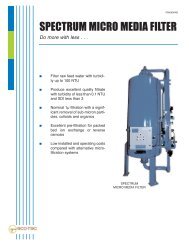
utilize a patented 1 technology called Recoflo. Recoflo ion<br />
<strong>exchange</strong> demineralizer ‘columns’ to do <strong>the</strong> same job are only<br />
6 inches in height as shown in Figure 1. In addtion to <strong>the</strong><br />
dramatic reduction in size, Recoflo demineralizers utilize only<br />
about one half <strong>the</strong> regenerant chemicals of a conventional cocurrent<br />
ion <strong>exchange</strong> system and produce higher purity water 2 .<br />
In addition to <strong>the</strong>ir short column height, Recoflo<br />
systems are characterized by a number of o<strong>the</strong>r features that<br />
differentiate <strong>the</strong>m from o<strong>the</strong>r ion <strong>exchange</strong> systems. These<br />
include:<br />
- counter-current regeneration<br />
- fine particle size resins<br />
- fully packed resin beds<br />
- pre-assembled and pre-tested skid mounted<br />
construction<br />
- very short cycle times in service and regeneration<br />
(i.e. minutes instead of hours)<br />
Figure 1: Typical Recoflo <strong>Ion</strong> Exchange<br />
Demineralizer<br />
A large number of Recoflo demineralizers have been<br />
installed <strong>for</strong> production of high purity water <strong>for</strong> applications<br />
such as boiler makeup water in cogeneration plants. It is<br />
likely that <strong>the</strong> pulp and paper industry will see this technology<br />
utilized <strong>for</strong> recovery boiler makeup water production in <strong>the</strong><br />
near future.<br />
Although <strong>the</strong> benefits of small size and low chemical<br />
consumption <strong>for</strong> water demineralization are obvious, Recoflo<br />
technology was in fact originally commercialized <strong>for</strong> chemical<br />
recovery and purification because of its unique ability to treat<br />
and produce very concentrated solutions. This is in contrast to
conventional ion <strong>exchange</strong> technology, which is generally<br />
limited to processing dilute solutions. Some of such<br />
applications that have been extensively exploited include:<br />
- recovery of metal salts such as chromium, copper,<br />
nickel, cobalt and zinc from electroplating<br />
rinsewaters<br />
- removal of non-process elements from concentrated<br />
electroplating electrolytes<br />
- purification of metal pickling, etching and anodizing<br />
baths<br />
- recovery of sulphuric acid from metal refinery<br />
electrolyte bleeds<br />
CHLORINE DIOXIDE GENERATOR ACID<br />
PURIFICATION<br />
In 1977 <strong>Eco</strong>-<strong>Tec</strong> developed a system called <strong>the</strong><br />
APU (Acid Purification Unit) <strong>for</strong> separation of metal salts<br />
from waste acid solutions. The APU utilizes an ion <strong>exchange</strong><br />
resin which has <strong>the</strong> ability to sorb acids from solution, while<br />
excluding metal salt of those acids. This sorption is<br />
reversible, in that <strong>the</strong> acid can be readily de-sorbed from <strong>the</strong><br />
resin with only water. It is thus possible, by alternately<br />
passing contaminated acid and water through a bed of this<br />
resin, to separate <strong>the</strong> free acid from <strong>the</strong> metal salt.<br />
There are basically two steps in <strong>the</strong> APU operating<br />
cycle (see Figure 2): In <strong>the</strong> upstroke, acid containing dissolved<br />
metal salt impurities is pumped into <strong>the</strong> bottom of a fixed bed<br />
of sorption resin. The free acid is sorbed by <strong>the</strong> resin as <strong>the</strong><br />
solution passes through <strong>the</strong> bed, so that a de-acidified metal<br />
salt solution is collected from <strong>the</strong> top of <strong>the</strong> bed. Next, during<br />
<strong>the</strong> downstroke, water is pumped down through <strong>the</strong> resin bed.<br />
Water strips <strong>the</strong> acid from <strong>the</strong> resin as it passes through <strong>the</strong><br />
bed, so that purified acid is collected from <strong>the</strong> bottom of <strong>the</strong><br />
bed. The total cycle time is typically only about 2-5<br />
minutes. No chemicals or significant energy inputs are<br />
required to operate <strong>the</strong> APU process.<br />
Sodium<br />
sulphate<br />
solution<br />
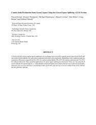
The APU was first commercialized <strong>for</strong> purification of<br />
sulphuric acid aluminum anodizing solutions 3 . Since that<br />
time, hundreds of units have been installed around <strong>the</strong> world on<br />
a wide variety of different acid recovery applications. A typical<br />
APU, which is shown in Figure 3 occupies less than 100 ft 2<br />
of floor space, excluding auxiliary tanks.<br />
The recent trend towards bleaching with chlorine<br />
dioxide has increased <strong>the</strong> quantity of byproduct acidic generator<br />
<strong>effluent</strong> produced, which must be disposed of. If all this<br />
material is recycled to recovery, one would expect to see a<br />
buildup in sulfur within <strong>the</strong> <strong>kraft</strong> cycle. Recently, <strong>the</strong> APU<br />
was adapted to treatment of acid <strong>effluent</strong>s from chlorine dioxide<br />
generators. The system, known as GAP (Generator Acid<br />
Purification) separates free sulphuric acid from sodium<br />
sulphate 4 . The GAP system can be used with ei<strong>the</strong>r<br />
atmospheric or vacuum generators.<br />
With atmospheric generators such as Mathieson or<br />
Solvay, <strong>the</strong> generator <strong>effluent</strong> is a concentrated liquor<br />
containing sulphuric acid and sodium sulphate with a low<br />
residual concentration of sodium chlorate. To avoid oxidation<br />
of <strong>the</strong> APU resin, <strong>the</strong> residual chlorate in <strong>the</strong> generator <strong>effluent</strong><br />
is first reduced with a chemical reducing agent such as sulfur<br />
dioxide 4 . The treated solution is <strong>the</strong>n fed through a filter to<br />
remove any suspended solids and on to <strong>the</strong> APU. The free<br />
sulphuric acid is taken up by <strong>the</strong> resin and a de-acidified<br />
sodium sulphate is collected. This sodium sulphate is recycled<br />
back to <strong>the</strong> recovery cycle. Since most of <strong>the</strong> sulphuric acid<br />
has been removed, <strong>the</strong> amount of caustic soda necessary to<br />
neutralize <strong>the</strong> acid that accompanies <strong>the</strong> sodium sulphate is<br />
substantially reduced. These savings go a long way towards<br />
paying off <strong>the</strong> capital investment in <strong>the</strong> GAP system.<br />
Purified sulphuric acid is recovered by water elution<br />
of <strong>the</strong> APU resin bed. This recovered sulphuric acid can be<br />
reused in various ways. The obvious approach is to recycle<br />
<strong>the</strong> acid back to <strong>the</strong> chlorine dioxide generator. In this case a<br />
small vacuum evaporator is installed to concentrate <strong>the</strong><br />
reclaimed acid back up to about 60% w/w. Many mills may<br />
be able to use <strong>the</strong> dilute acid <strong>for</strong> applications such as brown<br />
stock washing or tall oil acidulation so that an evaporator is<br />
not required.<br />
Sulphuric acid<br />
sodium<br />
sulphate solution<br />
Water<br />
Figure 2: APU Operating Cycle<br />
Sulphuric<br />
acid<br />
2<br />
Figure 3: Typical APU Used <strong>for</strong> Generator Acid<br />
Purification
Typical APU results from a GAP application are<br />
shown in Table I. The GAP system gives an atmospheric<br />
generator <strong>the</strong> operating cost benefits of a vacuum unit (e.g..<br />
SVP-Lite, R-8) without <strong>the</strong> high cost of equipment<br />
replacement. In fact, a GAP system can yield <strong>the</strong> same acid<br />
recovery efficiency as vacuum generators with salt cake<br />
washing equipment (e.g. SVP-SCW, R-10).<br />
Table I: Typical GAP System Per<strong>for</strong>mance<br />
basis: 20 TPD ClO 2 Production (Mathieson Generator)<br />
Na2SO4 H2SO4 Flow<br />
(g/L) (g/L) (L/h)<br />
generator <strong>effluent</strong> 288.0 453.5 4560<br />
purified acid 23.8 302.6 6125.8<br />
de-acidified salt 128.1 27.5 9188.8<br />
evaporator product 70.7 900.0 2059.6<br />
The GAP system can also be used with subatmospheric<br />
generators such as Eka Chemical’s SVP-Lite<br />
and Sterling Pulp Chemicals R-8. The system is <strong>the</strong>n called<br />
GAP-S, and is an attractive alternative to a salt cake washer or<br />
R-10 upgrade. The flowsheet <strong>for</strong> <strong>the</strong> GAP-S system is shown<br />
in Figure 4.<br />
ClO2/H2O<br />
Vacuum<br />
Filter<br />
SVP-Lite or<br />
R8Generator<br />
Na3H(SO4)2<br />
salt cake<br />
H2SO4<br />
Dissolving<br />
Tank<br />
APU<br />
water<br />
Figure 4: GAP-S Acid Purification System For<br />
Vacuum ClO 2 Generators<br />
Na2SO4 to<br />
recovery<br />
In <strong>the</strong> GAP-S system <strong>the</strong> sodium sesquisulphate salt<br />
cake obtained from <strong>the</strong> vacuum filter is first fully dissolved.<br />
The solution which contains sulphuric acid and sodium<br />
sulphate is <strong>the</strong>n fed to an APU. Due to <strong>the</strong> lower sulphuric<br />
acid concentration of <strong>the</strong> solution, destruction of <strong>the</strong> small<br />
amount of residual chlorate present is not necessary. As with<br />
<strong>the</strong> basic GAP system, <strong>the</strong> deacidified sodium sulphate<br />
byproduct is recycled back to recovery. A portion of <strong>the</strong><br />
purified dilute sulphuric acid obtained by water elution of <strong>the</strong><br />
APU resin is recycled back to <strong>the</strong> dissolving tank to dissolve<br />
<strong>the</strong> sodium sesquisulphate. By this means <strong>the</strong> acid<br />
concentration in <strong>the</strong> solution is <strong>for</strong>tified beyond what is<br />
possible by simply dissolving <strong>the</strong> sesquisulphate in water.<br />
The balance of <strong>the</strong> sulphuric acid eluate is recovered and<br />
3<br />
recycled back to <strong>the</strong> generator. Vacuum generators will often<br />
have sufficient evaporative capacity to handle <strong>the</strong> additional<br />
water load. If not, it may be possible to upgrade <strong>the</strong><br />
evaporation capacity of <strong>the</strong> generator at nominal cost. Because<br />
an evaporator is generally not required, capital costs <strong>for</strong> GAP-S<br />
are significantly less than <strong>for</strong> a GAP system.<br />
Typical per<strong>for</strong>mance <strong>for</strong> a GAP-S system is shown in<br />
Table II. While <strong>the</strong> GAP-S system provides similar recovery<br />
per<strong>for</strong>mance levels to a salt cake washing system, it is much<br />
more compact and less complex to operate.<br />
Table II - Typical GAP-S Per<strong>for</strong>mance<br />
basis: 20 TPD ClO 2 Production (SVP-Lite or R-8)<br />
Na2SO4 H2SO4 Flow (L/h)<br />
(g/L) (g/L)<br />
purified acid 81 126 1715<br />
de-acidified salt 308 7 2899<br />
CHLORIDE REMOVAL FROM ESP CATCH<br />
High levels of chloride and potassium impurities in<br />
<strong>kraft</strong> liquors are known to accelerate recovery boiler plugging<br />
under some circumstances. The current levels in some mills<br />
already require that boilers be shut down <strong>for</strong> water washing as<br />
frequently as every three months. As mills move towards<br />
higher levels of closure <strong>the</strong> current outlets <strong>for</strong> <strong>the</strong>se elements<br />
are reduced. This will result in even higher chloride and<br />
potassium concentrations throughout <strong>the</strong> <strong>kraft</strong> cycle.<br />
There<strong>for</strong>e, to reduce lost production due to boiler shutdowns<br />
control of <strong>the</strong>se elements will be necessary in many cases. In<br />
fact, elimination of only one boiler shutdown per year <strong>for</strong><br />
clean-out could easily warrant installation of a chloride<br />
removal system.<br />
The sticky temperature of <strong>the</strong> flue dust in a recovery<br />
boiler is defined as that temperature where <strong>the</strong> amount of liquid<br />
in <strong>the</strong> material is high enough <strong>for</strong> <strong>the</strong> mixture to stick on a<br />
metal surface. Laboratory and mill measurements have shown<br />
that <strong>the</strong> sticky temperature is reached when approximately 15%<br />
of <strong>the</strong> mixture becomes molten. Rapid plugging of <strong>the</strong><br />
recovery boiler can occur if <strong>the</strong> flue gas temperature exceeds<br />
T 15 in <strong>the</strong> generator bank.<br />
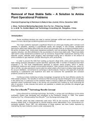
As Figure 5 shows, <strong>the</strong> chloride and potassium levels<br />
of <strong>the</strong> recovery boiler tube deposits have a significant effect on<br />
<strong>the</strong> sticky temperature, T 15 . If <strong>the</strong> chloride level can be reduced<br />
below 5% mole fraction, <strong>the</strong> sticky temperature should<br />
significantly increase and a reduced tendency <strong>for</strong> boiler<br />
plugging may be experienced. For example, at 5% K, by<br />
reducing <strong>the</strong> chloride level from 5% to 1.5%, <strong>the</strong> sticky<br />
temperature would increase from about 620°C to 740°C. It is<br />
important to note that when <strong>the</strong> deposit chloride levels are<br />
low, (i.e. less than 1.6 mole%) potassium has very little effect<br />
on <strong>the</strong> sticky temperature.<br />
These conclusions have been confirmed recently by<br />
o<strong>the</strong>r workers 6,7 and by mill practical experience. Many mills<br />
experiencing recovery boiler plugging problems have elected to<br />
discharge a portion (typically 15-50%) of <strong>the</strong>ir ESP catch, to<br />
provide an additional purge of chloride from <strong>the</strong> recovery cycle.<br />
These mills were able to achieve longer operation time<br />
between boiler water washes and chill-and-blow cleanings<br />
within a couple of months. They were also able to identify<br />
economic benefits resulting from <strong>the</strong> reduced chloride level in
<strong>the</strong> black liquor: eg. higher boiler efficiency, increased boiler<br />
throughput, higher steam temperature, lower sootblower<br />
maintenance and steam consumption. Of course, <strong>the</strong>re is a<br />
penalty to pay <strong>for</strong> <strong>the</strong>se benefits in terms of increased chemical<br />
consumption (mainly caustic soda).<br />
850<br />
800<br />
750<br />
700<br />
650<br />
600<br />
550<br />
500<br />
450<br />
K / (Na + K) mole %<br />
0<br />
5<br />
10<br />
20<br />
0 2 4 6 8 10 12 14 16 18 20<br />
Cl / (Na + K) mole %<br />
Figure 5: Effect of Chloride and Potassium on<br />
Deposit Sticky Temperature 5<br />
The Recoflo technology has recently been adapted into<br />
a new unit called an SSU (Salt S eparation Unit) <strong>for</strong><br />
separating different types of salts. The basic SSU process and<br />
equipment is <strong>the</strong> same as <strong>the</strong> APU shown in Figures 2 and 3,<br />
however <strong>the</strong> SSU employs a new type of sorption resin. The<br />
SSU resin is a special ion <strong>exchange</strong> resin with both cation and<br />
anion <strong>exchange</strong> groups existing on each resin particle. This<br />
resin can <strong>the</strong>re<strong>for</strong>e remove both anions and cations<br />
simultaneously.<br />
The SSU resin has unusual selectivities compared to<br />
conventional ion <strong>exchange</strong> resins. For example, <strong>the</strong> SSU<br />
resin has a very high selectivity <strong>for</strong> sodium chloride compared<br />
to o<strong>the</strong>r chemicals such as sodium sulphate and sodium<br />
carbonate. As a result, <strong>the</strong> SSU can remove sodium chloride<br />
from even concentrated solutions of sodium sulphate. The<br />
resin is very stable and under normal conditions should have an<br />
operating life time of many years. APU resins, which are very<br />
similar in composition and operated under similar<br />
hydrodynamic conditions, have shown lifetimes of 5-10 years<br />
in much harsher environments. As with <strong>the</strong> APU, <strong>the</strong> SSU<br />
resin is regenerated with only water. No chemicals or<br />
significant energy inputs are necessary. The process is<br />
<strong>the</strong>re<strong>for</strong>e very inexpensive to operate.<br />
It is well established that chloride becomes enriched<br />
in <strong>the</strong> electrostatic precipitator dust. This is <strong>the</strong>re<strong>for</strong>e <strong>the</strong><br />
logical place from which to attempt removal of chloride. A<br />
precipitator dust purification (PDP) system utilizing <strong>the</strong> SSU<br />
is shown in Figure 6. The dust is first dissolved in warm<br />
(i.e.. 40-60°C) water to produce a 28% sodium<br />
sulphate/sodium carbonate solution containing chloride<br />
contamination which is just below <strong>the</strong> saturation limit. The<br />
precipitator dust solution is fed to a pressure ‘pulse’ filter<br />
where insoluble solids, such as metal oxides and any carbon<br />
material, are removed. This filter is similar to <strong>the</strong> white liquor<br />
pressure filter frequently used in many <strong>kraft</strong> mills. Filtrate<br />
overflows from <strong>the</strong> filter’s collection chamber and is directed to<br />
<strong>the</strong> feed tank <strong>for</strong> treatment by <strong>the</strong> SSU. A typical back-pulse<br />
cycle <strong>for</strong> <strong>the</strong> pulse filter would be every 10 minutes and would<br />
4<br />
last about 15 seconds. During back-pulse, filtrate flows in<br />
reverse direction through <strong>the</strong> filter <strong>the</strong>reby removing solids<br />
from <strong>the</strong> filter elements. The solids <strong>the</strong>n settle to <strong>the</strong> bottom<br />
of <strong>the</strong> filter vessel where <strong>the</strong>y thicken to a concentration of 10-<br />
20%. Periodically, bottoms from <strong>the</strong> filter are withdrawn and<br />
ei<strong>the</strong>r purged from <strong>the</strong> system or bypassed around <strong>the</strong> SSU to<br />
<strong>the</strong> sulphate product tank, be<strong>for</strong>e recycle back to <strong>the</strong> recovery<br />
cycle.<br />
As with <strong>the</strong> APU (acid purification unit) described<br />
above, <strong>the</strong>re are two basic steps in <strong>the</strong> SSU operating cycle:<br />
upstroke and downstroke. During <strong>the</strong> upstroke, filtered ESP<br />
dust solution from <strong>the</strong> feed tank is pumped up through <strong>the</strong><br />
SSU resin bed. Sodium chloride is taken up by <strong>the</strong> resin and a<br />
purified sodium sulphate/carbonate solution is withdrawn from<br />
<strong>the</strong> top of <strong>the</strong> bed and collected in <strong>the</strong> sulphate product tank.<br />
In <strong>the</strong> downstroke, warm water is pumped into <strong>the</strong> top of <strong>the</strong><br />
bed eluting sodium chloride from <strong>the</strong> resin. A portion of <strong>the</strong><br />
chloride waste collected from <strong>the</strong> bottom of <strong>the</strong> bed is recycled<br />
back to <strong>the</strong> dissolving tank to dissolve more dust and <strong>the</strong><br />
remainder is purged from <strong>the</strong> system.<br />
Typical per<strong>for</strong>mance of a PDP system, based upon<br />
laboratory pilot plant runs, is shown in Table III. Dust<br />
samples from a number of different mills have been processed<br />
with comparable results. Note that <strong>the</strong> system removes as<br />
much as 97% of <strong>the</strong> chloride while recovering up to 99% of<br />
<strong>the</strong> sulphate and carbonate values. This compares very<br />
favorably with results recently reported 8 on evaporative<br />
crystallizer systems which show only 80% sulphate recovery<br />
and 90% chloride removal. The SSU does not show any<br />
selectivity <strong>for</strong> potassium, although as discussed above, this<br />
should not prove to be an issue <strong>for</strong> most mills. Potassium<br />
removal <strong>for</strong> an inland mill would typically be about 5 - 10%<br />
while <strong>for</strong> coastal mills with higher chloride levels, <strong>the</strong><br />
potassium removal would increase to about 10 - 15%.<br />
Table III - Precipitator Dust Purification System Results<br />
basis: 100 TPD ESP catch (typical inland mill)<br />
Na 33.6%<br />
K 7.6%<br />
SO 4 49.4%<br />
CO 3 7.0<br />
Cl 2.5%<br />
Flow<br />
(L/h)<br />
[Na]<br />
(g/L)<br />
[K]<br />
(g/L)<br />
[SO4]<br />
(g/L)<br />
[CO3]<br />
(g/L)<br />
[Cl]<br />
(g/L)<br />
Water 15,948<br />
Product 10,750 111.4 24.6 172.0 24.4 0.3<br />
Waste 6,557 11.0 2.1 2.7 0.2 14.0<br />
%Rem. 5.7% 5% 1% 0.5% 97%<br />
While <strong>the</strong> SSU itself does not consume any<br />
significant amounts of energy <strong>for</strong> its operation, recycle of <strong>the</strong><br />
purified salt cake solution will impose an additional<br />
evaporation load on <strong>the</strong> black liquor evaporators. To<br />
determine <strong>the</strong> impact of this load a typical mill is assumed to<br />
process 1,750 kg of black liquor solids (BLS) per tonne of<br />
pulp. Approximately 5% - 6% of this material, 96 kg-<br />
BLS/tonne-pulp, is captured as ESP dust and processed by <strong>the</strong><br />
PDP system. The purified salt cake solution recycled <strong>for</strong><br />
recovery is 28% w/w and <strong>the</strong>re<strong>for</strong>e <strong>the</strong> total additional<br />
evaporation required is roughly 235 kg-water per tonne of pulp<br />
if 100% of <strong>the</strong> dust is processed. In many cases processing
only a portion of <strong>the</strong> dust collected will suffice and <strong>the</strong> water<br />
load will be reduced proportionately. To avoid any<br />
precipitation or scaling, <strong>the</strong> point at which this solution is<br />
introduced must be carefully selected.<br />
A computer based model has recently been used to<br />
predict <strong>the</strong> impact of <strong>the</strong> PDP process on an actual <strong>kraft</strong> mill 8 .<br />
Data collected from Georgia-Pacific’s Leaf River mill in New<br />
Augusta, MS were used as <strong>the</strong> basis <strong>for</strong> this model. This ECF<br />
mill processes softwood and mixed hardwood to produce 1,630<br />
ADMT/d of pulp. A best management practices (BMP) case<br />
was considered where <strong>the</strong> screen room has been closed and<br />
liquor losses reduced to give a soda make-up of 8.66 kg-<br />
Na 2 O/ADMT. The results of this simulation <strong>for</strong> treatment of<br />
all <strong>the</strong> ESP dust are shown in Table IV. It should be noted<br />
that <strong>the</strong> mill data used <strong>for</strong> <strong>the</strong> simulation were collected from a<br />
softwood run.<br />
As expected, <strong>the</strong> simulation predicts a large reduction<br />
in <strong>the</strong> chloride content of <strong>the</strong> ESP dust and black liquor, but a<br />
much smaller drop in <strong>the</strong> potassium when treated by <strong>the</strong> PDP<br />
process. While treatment by evaporative crystallization<br />
removes 90% of <strong>the</strong> potassium, a comparison of <strong>the</strong> sticky<br />
temperatures <strong>for</strong> <strong>the</strong>se processes shows <strong>the</strong>re is no significant<br />
difference. This again illustrates <strong>the</strong> minor influence of<br />
potassium on sticky temperature at low chloride levels.<br />
Table IV - Simulation of PDP Impact on Kraft Process 8<br />
Cl in fired black<br />
liquor (%w/w)<br />
Cl/(Na+K) in<br />
ESP dust (mole%)<br />
K/(Na+K) in ESP<br />
dust (mole%)<br />
ESP dust sticky<br />
temp. (C°)<br />
BMP<br />
Base Case<br />
With PDP<br />
With<br />
Evaporative<br />
Crystallizer<br />
0.76 0.084 0.087<br />
5.8 0.66 0.75<br />
11.8 9.1 2.1<br />
565 770 790<br />
Even though simulation data and literature references<br />
document <strong>the</strong> greater impact of chloride on plugging, some<br />
mills, those processing hardwood <strong>for</strong> example, may require<br />
more potassium removal than is currently possible using <strong>the</strong><br />
PDP system. If this is <strong>the</strong> case, it should be noted that up to<br />
20% of <strong>the</strong> dust could be bled from <strong>the</strong> system while still<br />
giving <strong>the</strong> same sulphate recovery efficiency as <strong>the</strong> evaporative<br />
crystallization process. This would <strong>the</strong>n allow more than four<br />
times <strong>the</strong> current potassium removal efficiency. Work is also<br />
currently underway to develop a potassium removal system<br />
that could be added on to <strong>the</strong> PDP system <strong>for</strong> those mills that<br />
do require more K removal.<br />
A separate project is also underway to evaluate <strong>the</strong><br />
use of <strong>the</strong> SSU <strong>for</strong> chloride removal from make-up caustic.<br />
This would of course reduce <strong>the</strong> overall input of chloride to <strong>the</strong><br />
<strong>kraft</strong> mill and offers ano<strong>the</strong>r approach to chloride control.<br />
The PDP system has a number of significant<br />
advantages compared to o<strong>the</strong>r competitive <strong>technologies</strong><br />
currently proposed <strong>for</strong> precipitator dust purification, such as<br />
5<br />
evaporative crystallization and electrodialysis. These include:<br />
- significantly lower capital and installed cost<br />
- lower operating cost<br />
- better sodium sulphate and carbonate recovery<br />
efficiency<br />
- better chloride removal efficiency<br />
- significantly less floor and head space<br />
METALS REMOVAL FROM BLEACH<br />
FILTRATES<br />
Calcium, manganese and o<strong>the</strong>r multi-valent mineral<br />
non-process elements (NPE’s) enter <strong>the</strong> mill via wood, water<br />
and chemicals. Normally, <strong>the</strong>se impurities leave <strong>the</strong> mill in<br />
grits and dregs as part of <strong>the</strong> causticizing operation, as well as<br />
through inadvertent losses of cooking liquor. Loss of<br />
impurities to <strong>the</strong> bleach plant via <strong>the</strong> brownstock also<br />
provides a significant purge in normal operations. During<br />
contact in <strong>the</strong> acidic bleaching stages, metals are leached from<br />
<strong>the</strong> pulp fibres into <strong>the</strong> bleach filtrates. When bleach filtrate<br />
streams are recycled, NPE’s accumulate. As levels increase,<br />
mineral deposits (scale) <strong>for</strong>m in pipes and equipment.<br />
<strong>Ion</strong> <strong>exchange</strong>-type water softening systems have long<br />
been used to prevent mineral scaling in low pressure boilers.<br />
The process is similar to <strong>the</strong> cation <strong>exchange</strong> portion of a<br />
water demineralizer except that <strong>the</strong> ion <strong>exchange</strong> resin is<br />
regenerated with sodium chloride instead of acid. The scale<br />
causing metals such as calcium and magnesium are <strong>the</strong>n<br />
<strong>exchange</strong>d with sodium on <strong>the</strong> resin. The advantages that<br />
Recoflo offers <strong>the</strong> demineralization process (i.e.. compact size,<br />
low operating cost) are also available <strong>for</strong> water softening.<br />
Removal of multi-valent metal NPE’s to avoid<br />
scaling was recognized by Champion International to be an<br />
essential requirement <strong>for</strong> its BFR® bleach filtrate recycle<br />
system. After evaluating various alternatives, Champion<br />
elected to install an <strong>Eco</strong>-<strong>Tec</strong> Recoflo cation <strong>exchange</strong> system<br />
at its Canton NC BFR demonstration plant. In this<br />
installation, which employs oxygen delignification and an<br />
ECF bleaching sequence, a portion of <strong>the</strong> acidic D1 filtrate is<br />
passed through <strong>the</strong> metal removal process (MRP) as shown in<br />
Figure 7. The balance of <strong>the</strong> D1 filtrate is used on <strong>the</strong> fiber<br />
line pre-washer.<br />
The MRP consists of a coarse strainer to remove<br />
large fibers, followed by three multi-media filters (two<br />
operating in parallel, one in backwash) <strong>for</strong> removal of <strong>the</strong><br />
remaining suspended solids. The filtered solution is <strong>the</strong>n<br />
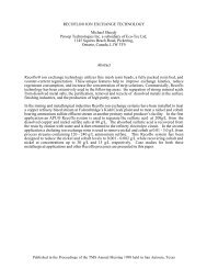
passed though two parallel cation <strong>exchange</strong> units (IX2, IX2),<br />
each employing resin beds 60 inches in diameter by 6 inches<br />
in height. One of <strong>the</strong>se units is shown in Figure 8. The total<br />
net flow that can be treated by <strong>the</strong> MRP is approximately 800<br />
gallons per minute when fully operational. The purified D1<br />
filtrate is recycled to <strong>the</strong> D1 washer lower pond.<br />
The multi-media filters are backwashed several times<br />
each day with mill water to waste. Typical of Recoflo, <strong>the</strong> ion<br />
<strong>exchange</strong> units have very short cycle times. The units are<br />
normally in service <strong>for</strong> only 5-6 minutes and offstream, <strong>for</strong><br />
regeneration, <strong>for</strong> 1-2 minutes.<br />
The MRP was commissioned in November 1995.<br />
Although a number of mechanical problems were experienced<br />
during <strong>the</strong> initial operation, <strong>the</strong>se have been worked out and<br />
<strong>the</strong> system is currently working reliably. Filtration, in<br />
particular proved to be a significant challenge due <strong>the</strong><br />
unexpectedly high concentration of fine fibrous contamination
in <strong>the</strong> filtrates. Champion has reported 9,10 that <strong>the</strong> system has<br />
met <strong>the</strong> original objectives by removing 85-90% of <strong>the</strong><br />
hardness (i.e. calcium, manganese, magnesium) from <strong>the</strong> D1<br />
stage filtrates over extended periods of operation during 1997.<br />
83 rd Annual Meeting of CPPA, Montreal, January<br />
28-31, 1997.<br />
5. TRAN, H.N., “How does a Kraft Recovery Boiler<br />
Become Plugged”, Tappi Journal, (November 1986).<br />
6. TRAN, H.N., BARHAM, D., REEVE, D.W.,<br />
“Chloride and Potassium in <strong>the</strong> Kraft Chemical<br />
Recovery Cycle”, Pulp & Paper Canada 91:5 (1990)<br />
7. BACKMAN, R., SKRIFVARS, B.J., HUPA, M.,<br />
SIISKONEN, P., MANTYNIEMI, Flue Gas and<br />
Dust Chemistry in Recovery Boilers with High<br />
Levels of Chlorine and Potassium, Journal of Pulp<br />
and Paper Science: 22 (4) (April 1996).<br />
8. MINDAY, M., “An Overview of Various Strategies<br />
<strong>for</strong> Balancing Saltcake, Chloride, and Potassium<br />
Levels in an ECF Kraft Mill”, 1997 TAPPI<br />
Minimum Effluent Mills Symposium, San<br />
Francisco, CA, Oct. 23-24, 1997.<br />
Figure 8: Recoflo <strong>Ion</strong> Exchange Unit Installed at<br />
Champion, Canton NC<br />
SUMMARY AND CONCLUSIONS<br />
New ion <strong>exchange</strong> systems have been developed<br />
which are capable of removing impurities from pulping and<br />
bleaching liquors and adjusting chemical balances. These<br />
systems are unique in that <strong>the</strong>y all utilize extremely small ion<br />
<strong>exchange</strong> columns and employ little or no chemicals <strong>for</strong> <strong>the</strong>ir<br />
operation. The small space requirements and low operating<br />
costs that result should make <strong>the</strong>m very attractive to <strong>the</strong><br />
industry. While <strong>the</strong>se systems address a number of key<br />
concerns relating to increased mill closure, in order to<br />
successfully integrate <strong>the</strong>m into a mill it is essential to<br />
consider what secondary effect operation of <strong>the</strong>se systems may<br />
have.<br />
9. CARON J. R., DELANEY, G., “Initial Learnings<br />
From The BFR Demonstration”, 1997 TAPPI<br />
Minimum Effluent Mills Symposium, San<br />
Francisco, CA, Oct. 23-24, 1997.<br />
10. STRATTON, S.C., FERGUSON, M., “Progress<br />
report on <strong>the</strong> BFR technology demonstration,<br />
December 1996”, Pulp & Paper Canada, 99 :3 (1998)<br />
REFERENCES<br />
1. BROWN, C.J., US. Patent 4,673,507, June 16 1987.<br />
2. FLETCHER, C., PACE, V., “New Per<strong>for</strong>mance<br />
Standards For Demineralization Set By Recoflo<br />
<strong>Tec</strong>hnology”, Annual Meeting of <strong>the</strong> American<br />
Power Conference, April 18-20, 1995, Chicago, IL,<br />
sponsored by Illinois Institute of <strong>Tec</strong>hnology.<br />
3. BROWN, C.J., DAVY, D. SIMMONS, P.J.,<br />
“Purification of Aluminum Sulphuric Acid Anodizing<br />
Solutions”, Plating and Surface Finishing, 66, 54-57<br />
(January 1979).<br />
4. PALEOLOGOU, M., THOMPSON, R.,<br />
BERRY, R., BROWN, C.J., SHEEDY, M, “The<br />
Generator Acid Purification (GAP) System Reduces<br />
Caustic Make-Up Requirements at Kraft Mills”, Proc.<br />
6
Pulse filter<br />
water<br />
water<br />
ESP<br />
dust<br />
SSU<br />
NaCl<br />
waste<br />
dissolving<br />
tank<br />
NPE<br />
sludge<br />
feed<br />
tank<br />
sulfate<br />
product<br />
tank<br />
to<br />
evaps<br />
recycle<br />
Figure 6: Precipitator Dust Purification System<br />
HW<br />
WW<br />
WOOD<br />
Kraft<br />
Cooking<br />
Oxygen<br />
Delig.<br />
PB<br />
D1 EOP D2<br />
PULP<br />
Sewer<br />
Sewer<br />
Media<br />
Filter 1<br />
Media<br />
Filter 2<br />
Media<br />
Filter 3<br />
Metal<br />
Removal<br />
Process<br />
Mill<br />
Water<br />
IX1<br />
IX2<br />
Sewer<br />
Strainer<br />
Reclaimed<br />
Fibers<br />
NaCl<br />
NaCl<br />
Figure 7: Metals Removal Process at Champion<br />
7