1500 BROCHURE.pdf - Emerson Swan
1500 BROCHURE.pdf - Emerson Swan
1500 BROCHURE.pdf - Emerson Swan

You also want an ePaper? Increase the reach of your titles
YUMPU automatically turns print PDFs into web optimized ePapers that Google loves.
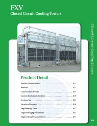
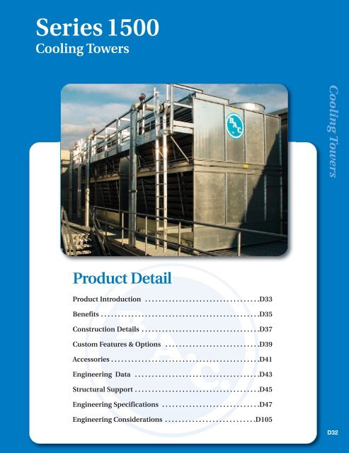
Series <strong>1500</strong><br />
Cooling Towers<br />
Cooling Towers<br />
Product Detail<br />
Product Introduction . . . . . . . . . . . . . . . . . . . . . . . . . . . . . . . . . .D33<br />
Benefits . . . . . . . . . . . . . . . . . . . . . . . . . . . . . . . . . . . . . . . . . . . . . . .D35<br />
Construction Details . . . . . . . . . . . . . . . . . . . . . . . . . . . . . . . . . . .D37<br />
Custom Features & Options . . . . . . . . . . . . . . . . . . . . . . . . . . . .D39<br />
Accessories . . . . . . . . . . . . . . . . . . . . . . . . . . . . . . . . . . . . . . . . . . . .D41<br />
Engineering Data . . . . . . . . . . . . . . . . . . . . . . . . . . . . . . . . . . . . .D43<br />
Structural Support . . . . . . . . . . . . . . . . . . . . . . . . . . . . . . . . . . . . .D45<br />
Engineering Specifications . . . . . . . . . . . . . . . . . . . . . . . . . . . . .D47<br />
Engineering Considerations . . . . . . . . . . . . . . . . . . . . . . . . . . .D105<br />
D32
D33<br />
Spotlight
(Before)<br />
(After)<br />
TriArmor® Corrosion Protection System<br />
Ideal Replacement Unit<br />
Easy Maintenance Features<br />
Sound Sensitive Applications<br />
Independent Fans<br />
D34
Benefits<br />
Series <strong>1500</strong><br />
Ideal Replacement Unit<br />
• Support Steel – Units are designed to mount<br />
directly on existing support steel of many cooling<br />
towers (both crossflow and counterflow).<br />
• Electrical Service – Fan motor configurations<br />
can be supplied to match existing wiring.<br />
• Enclosures – Units fit in most existing<br />
enclosures with little or no modifications due to<br />
the single side air inlet design.<br />
Single Side Air Inlet Provides Installation<br />
Flexibility in Tight Layouts<br />
Before<br />
After<br />
Counterflow Cooling Tower Replacement<br />
Low Energy Consumption<br />
• Evaporative cooling equipment minimizes the energy consumption of the entire system because it<br />
provides lower condenser water temperatures. Owners save money while conserving natural<br />
resources and reducing environmental impact.<br />
• Series <strong>1500</strong> Cooling Towers provide the heat rejection required at the lowest possible energy<br />
input via:<br />
• High efficiency, low horsepower axial fans<br />
• High efficiency BACross ® Fill, which provides maximum air/water contact time at low air<br />
pressure drops<br />
• Premium efficient/VFD duty motors as standard<br />
• Independent fan motors (optional, see page D40 for details)<br />
• Variable frequency drives (optional, see page K1 for details)<br />
• BALTIGUARD Fan System (optional, see page D40 for details)<br />
• BALTIGUARD PLUS Fan System (optional, see page D40 for details)<br />
• All units meet or exceed ASHRAE Standard 90.1 energy efficiency requirements.<br />
D35<br />
Baltimore Aircoil Company
Low Installed Cost<br />
• Single Side Air Inlet – Units can be placed close<br />
to solid walls, reducing the size of enclosures and<br />
allowing for more profitable use of premium space.<br />
• Modular Design – The modular design minimizes<br />
the size and weight of the heaviest lift, allowing for<br />
the use of smaller, less costly cranes.<br />
Series <strong>1500</strong> with Optional<br />
External Service Platform<br />
Easy Maintenance<br />
The Unit Shown Ships in Two Pieces to<br />
Minimize Shipping and Rigging Costs<br />
• Easy Cleaning – The fill surface is elevated above the<br />
sloped cold water basin floor to facilitate flushing of dirt and<br />
debris from this critical area.<br />
• Hinged Access Doors and Standard Internal Walkway –<br />
Provide easy entry to the spacious plenum for routine<br />
drive maintenance.<br />
Cooling Towers<br />
• Accessibility – Make-up, drain, overflow and optional basin<br />
accessories are accessible from outside the unit.<br />
• Inlet Strainer – Dirt and debris are collected by an integral<br />
strainer before reaching the hot water basin, keeping<br />
nozzles clean.<br />
Access to Strainer, Make-up and<br />
Basin Accessories from Outside<br />
the Tower<br />
Standard Inlet Strainer<br />
Reliable Year-Round Operation<br />
• BALTIDRIVE ® Power Train – Backed by a 5-year fan motor<br />
and drive warranty, the BALTIDRIVE ® Power Train utilizes<br />
special corrosion-resistant materials of construction and<br />
state-of-the-art technology to ensure ease of maintenance and<br />
reliable year-round performance.<br />
• Separate Air Inlet Louvers – Reduce the potential for<br />
excessive scale build-up and damaging ice formations at the<br />
air/water interface by providing a line of sight from the outside<br />
the unit into the fill.<br />
Long Service Life<br />
• Materials of Construction – Various materials are available to meet the corrosion resistance, unit<br />
operating life, and budgetary requirements of any project (see page D39 for construction options).<br />
...because temperature matters <br />
D36
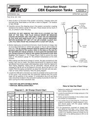
Construction Details<br />
Series <strong>1500</strong><br />
3<br />
2<br />
1<br />
4<br />
8<br />
6<br />
7<br />
D37<br />
Baltimore Aircoil Company
1<br />
Heavy-Duty Construction<br />
• G-235 (Z700 metric) hot-dip galvanized<br />
steel panels<br />
2<br />
BALTIDRIVE ® Power Train<br />
• Premium quality, solid-backed, multi-groove belt<br />
• Corrosion resistant cast aluminum sheaves<br />
• Heavy-duty bearings L 10 40,000 hours<br />
(280,000 hour average life)<br />
• Premium efficient/VFD<br />
duty motors as standard<br />
• 5-year motor and drive warranty<br />
5<br />
BACross ® Fill with Integral<br />
Drift Eliminators (Not Shown)<br />
• High efficiency heat transfer surface<br />
• Polyvinyl chloride (PVC)<br />
• Impervious to rot, decay and biological attack<br />
• Flame spread rating of 5 per ASTM E84<br />
6<br />
FRP Air Inlet Louvers<br />
• Corrosion resistant<br />
• Maintenance free<br />
• UV-protected finish<br />
Cooling Towers<br />
3 Low Horsepower Axial Fan<br />
• High efficiency<br />
• Quiet operation<br />
• Corrosion resistant<br />
4 Water Distribution System<br />
• Large orifice non-clog nozzles<br />
• Steel covers in easy to remove sections<br />
• Low pump head gravity distribution basin<br />
• Integral strainer<br />
7 Cold Water Basin<br />
• Sloped cold water basin for easy cleaning<br />
• Suction strainer with anti-vortex hood<br />
• Adjustable water make-up assembly<br />
• Integral internal walkway as standard<br />
8 Hinged Access Doors<br />
• Inward swinging door on each end wall<br />
...because temperature matters <br />
D38
Custom Features and Options<br />
Series <strong>1500</strong><br />
Construction Options<br />
• Standard Construction:<br />
Steel panels and structural elements are constructed of heavy-gauge G-235 (Z700) hot-dip<br />
galvanized steel.<br />
• Optional Thermosetting Hybrid Polymer:<br />
A thermosetting hybrid polymer coating used to extend equipment life, is applied to select hot-dip<br />
galvanized steel components of the cooling tower. The thermosetting hybrid polymer has been tested<br />
to withstand 6000 hours in a 5% salt spray without blistering, chipping, or loss of adhesion.<br />
• Optional TriArmor ® Corrosion Protection System:<br />
The cold water basin is constructed of the TriArmor ® Corrosion Protection System. The system<br />
consists of a heavy-gauge G-235 galvanized steel substrate fully encapsulated by a thermosetting<br />
hybrid polymer further protected by a polyurethane barrier applied to all submerged surfaces of the<br />
cold water basin. The basin is leak tested at the factory and warranted against leaks and corrosion for<br />
5 years.<br />
• Optional Stainless Steel Cold Water Basin:<br />
A Type 304 stainless steel cold water basin is available. Seams between panels inside the cold<br />
water basin are welded. The basin is leak tested at the factory and welded seams are provided with<br />
a 5-year leak-proof warranty.<br />
• Optional Stainless Steel Hot and Cold Water Basins:<br />
Type 304 stainless steel hot water basins are provided in addition to the cold water basin.<br />
• Optional Stainless Steel Construction:<br />
Steel panels and structural elements are constructed of Type 304 stainless steel. Seams between<br />
panels inside the cold water basin are welded. The basin is leak tested at the factory and welded<br />
seams are provided with a 5-year leak-proof warranty.<br />
See page M20 for more details on the materials described above.<br />
Fan Drive System<br />
The fan drive system provides the cooling air<br />
necessary to reject unwanted heat from the system<br />
to the atmosphere. The standard fan drive system on<br />
the Series <strong>1500</strong> is the BALTIDRIVE ® Power Train.<br />
This BAC engineered drive system consists of a<br />
specially designed powerband and cast aluminum<br />
sheaves located on minimum shaft centerline<br />
distances to maximize belt life. A premium efficient<br />
cooling tower duty fan motor provides maximum<br />
performance for cooling tower service and is backed<br />
by BAC’s comprehensive 5-year motor and fan drive<br />
warranty.<br />
BALTIDRIVE ® Power Train System<br />
D39<br />
Baltimore Aircoil Company
Independent Fan Operation<br />
Models 15296 through 15425 are provided with one<br />
fan motor driving two fans as standard. The<br />
independent fan option consists of one fan motor and<br />
drive assembly for each fan to allow independent<br />
operation, adding an additional step of fan cycling<br />
and capacity control.<br />
BALTIGUARD Fan System<br />
The BALTIGUARD Fan System consists of two<br />
standard single-speed fan motor and drive<br />
assemblies. One drive assembly is sized for full<br />
speed and load, and the other is sized approximately<br />
2/3 speed and consumes only 1/3 the design<br />
BALTIGUARD Fan System<br />
horsepower. This configuration allows the reserve<br />
capacity of a standby motor in the event of failure. As a minimum, approximately 70% capacity will be<br />
available from the low horsepower motor, even on a design wet-bulb day. Controls and wiring are the<br />
same as those required for a two-speed, two-winding motor. On some units the standby fan motor can<br />
be increased to the size of the main motor for 100% redundancy.<br />
Cooling Towers<br />
BALTIGUARD PLUS TM Fan System<br />
The BALTIGUARD PLUS TM Fan System builds on the advantages of the BALTIGUARD Fan System by<br />
adding a VFD to one motor. For more information on the BALTIGUARD PLUS TM Fan System refer to<br />
page K1.<br />
Low Sound Alternatives<br />
The low sound levels generated by Series <strong>1500</strong> Cooling<br />
Towers make them suitable for installation in most<br />
environments.<br />
• For situations when one direction is sound sensitive, the<br />
unit can be oriented so that the side opposite the air inlet<br />
faces the sound-sensitive direction.<br />
• The Series <strong>1500</strong> is also available with a low sound fan or<br />
a Whisper Quiet Fan. The thermal performance with<br />
either fan option has been certified in accordance with CTI<br />
Standard STD-201.<br />
Whisper Quiet Fans<br />
• For extremely sound sensitive installations, factory designed, tested and rated sound attenuation is<br />
available for both the air intake and discharge.<br />
Equipment Controls<br />
BAC control panels are specifically designed to work seamlessly with all BAC units and engineered to<br />
meet you particular application. For more on BAC Equipment Controls, see section K.<br />
...because temperature matters <br />
D40
Accessories<br />
Series <strong>1500</strong><br />
Service Platforms<br />
For access to the motor and drive assemblies on Models<br />
15296 through 15425, an internal ladder with or without<br />
upper service platform with handrails is available. For<br />
external service, louver face platforms and access door<br />
platforms are options that can be added to the cooling tower<br />
either when the unit is purchased or as an aftermarket item.<br />
Safety gates are available for all handrail openings supplied<br />
by BAC. All components are designed to meet OSHA<br />
requirements.<br />
External Platform at Louver Face<br />
Vibration Cutout Switch<br />
A factory mounted vibration cutout switch is available to effectively protect against rotating equipment<br />
failure. BAC can provide either a mechanical or solid-state electronic vibration cutout switch in a<br />
NEMA 4 enclosure to ensure reliable protection. Additional contacts can be provided on either switch<br />
type to activate an alarm. Remote reset capability is also available on either switch type.<br />
Basin Heaters<br />
Standard Internal Walkway<br />
Cooling towers exposed to below freezing ambient temperatures require protection to prevent freezing<br />
of the water in the cold water basin when the unit is idle. Factory-installed electric immersion heaters,<br />
which maintain +40°F (4.4°C) water temperature, are a simple and inexpensive way of providing such<br />
protection.<br />
Heater kW Data<br />
Internal Ladder and Service Platform<br />
Model Number Number of Heaters 0ºF (-17.8ºC) Ambient Heaters (kW) Number of Heaters -20ºF (-28.9ºC) Ambient Heaters (kW)<br />
15146 to 15282 1 8 1 12<br />
15296 to 15425 1 12 1 16<br />
Factory Mutual Approval construction is available as an option.<br />
D41<br />
Baltimore Aircoil Company
Electric Water Level Control Package<br />
The electric water level control replaces the standard<br />
mechanical make-up valve when a more precise<br />
water level control is required. This package consists<br />
of a conductance-actuated level control mounted in<br />
the basin and a solenoid activated valve in the<br />
make-up water line. The valve is slow closing to<br />
minimize water hammer.<br />
Extended Lubrication Lines<br />
Extended lubrication lines are available for lubrication<br />
of the fan shaft bearings. Fittings are located inside<br />
the plenum area next to the access door.<br />
High Temperature Fill<br />
If operation above 120°F (48.9°C) is anticipated, an<br />
optional high temperature fill material is<br />
available which increases the maximum allowable<br />
entering water temperature to 135°F (57.2°C).<br />
Electric Water Level Control Package<br />
Cooling Towers<br />
Air Inlet Screens<br />
Wire mesh screens are available factory-installed<br />
over the air inlet louvers to prevent debris from<br />
entering the tower.<br />
Basin Sweeper Piping<br />
Basin sweeper piping is an effective method of<br />
eliminating sediment that may collect in the cold<br />
water basin of the tower. A complete piping system,<br />
including nozzles, is provided in the tower basin to<br />
connect to side stream filtration equipment (by<br />
others). For more information on filtration systems,<br />
see page M163.<br />
Side Outlet Depressed Sump Box<br />
Grease Fittings at the Access Door (inset) and<br />
Bearings with the Extended Lubrication Line Option<br />
A side outlet depressed sump box is available for<br />
field installation below the base of the tower to<br />
facilitate jobsite piping. The outlet connection is<br />
designed to mate with an ASME Class 150 Flat Face<br />
flange. See the Connection Guide (page M60) for<br />
more information on standard and optional unit connection types.<br />
Basin Sweeper Piping<br />
...because temperature matters <br />
D12 D42
Engineering Data<br />
Do not use for construction. Refer to factory certified dimensions. This handbook includes data current<br />
at the time of publication, which should be reconfirmed at the time of purchase. Up-to-date engineering<br />
data, free product selection software, and more can be found at www.BaltimoreAircoil.com.<br />
Series <strong>1500</strong><br />
Single Cell Unit<br />
Ind. Fan<br />
Weights (lbs)<br />
Dimensions<br />
Model<br />
Number<br />
Nominal<br />
Tonnage 9 Motor HP<br />
Motor<br />
Option<br />
Fan<br />
(CFM) Operating 1 Shipping<br />
Heaviest<br />
Section L H A C D<br />
15146 146 7.5 N/A 40,320 7,920 3,940 3,940<br />
15160 160 10 N/A 44,190 7,940 3,960 3,960<br />
15176 176 15 N/A 48,160 7,990 4,010 4,010<br />
15162 162 7.5 N/A 43,080 8,610 4,200 4,200<br />
15177 177 10 N/A 47,070 8,630 4,220 4,220<br />
15201 201 15 N/A 53,540 8,690 4,280 4,280<br />
15219 219 20 N/A 58,240 8,710 4,300 4,300<br />
15200 200 10 N/A 52,320 11,430 5,350 2,770<br />
15227 227 15 N/A 59,380 11,490 5,410 2,780<br />
15250 250 20 N/A 65,400 11,510 5,430 2,800<br />
15214 214 10 N/A 56,610 12,450 5,640 2,920<br />
15245 245 15 N/A 64,810 12,510 5,700 2,920<br />
15270 270 20 N/A 71,420 12,530 5,720 2,920<br />
15282 282 25 N/A 74,600 12,610 5,800 2,920<br />
15296 296 15 (2) 7.5 77,440 15,540 6,750 3,540<br />
15325 325 20 (2) 10 85,030 15,590 6,800 3,590<br />
15350 350 25 (2) 15 91,560 15,640 6,850 3,640<br />
15368 368 30 (2) 15 96,280 15,660 6,870 3,660<br />
15310 310 15 (2) 7.5 82,000 17,050 7,070 3,540<br />
15340 340 20 (2) 10 89,940 17,100 7,120 3,590<br />
15365 365 25 (2) 15 96,550 17,150 7,170 3,640<br />
15385 387 30 (2) 15 101,840 17,180 7,200 3,670<br />
15425 428 40 (2) 20 112,340 17,450 7,470 3,940<br />
Multi-Cell Units<br />
15146-2 292 (2) 7.5 N/A 80,640 15,840 7,880 3,940<br />
15160-2 320 (2) 10 N/A 88,380 15,880 7,920 3,960<br />
15176-2 352 (2) 15 N/A 96,320 15,890 8,020 4,010<br />
15162-2 324 (2) 7.5 N/A 86,160 17,220 8,400 4,200<br />
15177-2 354 (2) 10 N/A 94,140 17,260 8,440 4,220<br />
15201-2 402 (2) 15 N/A 106,900 17,380 8,560 4,280<br />
15219-2 438 (2) 20 N/A 116,480 17,420 8,600 4,300<br />
15200-2 400 (2) 10 N/A 104,640 22,860 10,700 2,770<br />
15227-2 454 (2) 15 N/A 118,760 22,980 10,820 2,780<br />
15250-2 500 (2) 20 N/A 130,800 23,020 10,860 2,800<br />
15214-2 428 (2) 10 N/A 113,220 24,900 11,280 2,920<br />
15245-2 490 (2) 15 N/A 129,620 25,020 11,400 2,920<br />
15270-2 540 (2) 20 N/A 142,840 25,060 11,440 2,920<br />
15282-2 564 (2) 25 N/A 149,200 25,220 11,600 2,920<br />
15296-2 592 (2) 15 (4) 7.5 154,880 31,080 13,500 3,540<br />
15325-2 650 (2) 20 (4) 10 170,060 31,180 13,600 3,590<br />
15350-2 700 (2) 25 (4) 15 183,120 31,280 13,700 3,640<br />
15368-2 736 (2) 30 (4) 15 192,560 31,320 13,740 3,660<br />
15310-2 620 (2) 15 (4) 7.5 164,000 34,100 14,140 3,540<br />
15340-2 680 (2) 20 (4) 10 179,880 34,200 14,240 3,590<br />
15365-2 730 (2) 25 (4) 15 193,100 34,300 14,340 3,640<br />
15385-2 774 (2) 30 (4) 15 203,680 34,360 14,400 3,670<br />
15425-2 856 (2) 40 (4) 20 224,680 34,900 14,940 3,940<br />
Inlet<br />
Conn. 2<br />
8’ 5-3/4” 10’ 2-7/8” N/A 9’ 8-5/8” 4’ 2-7/8” 6”<br />
8’ 5-3/4” 11’ 6-7/8” N/A 11’ 0-5/8”<br />
4’ 2-7/8”<br />
8’ 5-3/4” 14’ 3-3/8” 7’ 4-3/4” 13’ 9-1/4” 4’ 2-7/8” 6”<br />
8’ 5-3/4” 15’ 7-3/8” 8’ 8-3/4” 15’ 1-1/4”<br />
12’ 1-1/4” 14’ 3-3/8” 7’ 4-3/4” 13’ 9-1/4”<br />
4’ 2-7/8”<br />
6’ 0-5/8”<br />
12’ 1-1/4” 15’ 7-3/8” 8’ 8-3/4” 15’ 1-1/4” 6’ 0-5/8” 8”<br />
17’ 2” 10’ 2-7/8” N/A 9’ 8-5/8” 4’ 2-7/8” (2) 6”<br />
17’ 2” 11’ 6-7/8” N/A 11’ 0-5/8” 4’ 2-7/8” (2) 6”<br />
17’ 2” 14’ 3-3/8” 7’ 4-3/4” 13’ 9-1/4” 4’ 2-7/8” (2) 6”<br />
17’ 2” 15’ 7-3/8” 8’ 8-3/4” 15’ 1-1/4” 4’ 2-7/8” (2) 6”<br />
24’ 5” 14’ 3-3/8” 7’ 4-3/4” 13’ 9-1/4” 6’ 0-5/8” (2) 8”<br />
24’ 5” 15’ 7-3/8” 8’ 8-3/4” 15’ 1-1/4” 6’ 0-5/8” (2) 8”<br />
6”<br />
6”<br />
8”<br />
D43<br />
Baltimore Aircoil Company
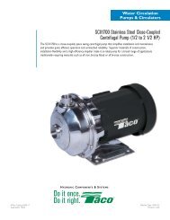
6<br />
AIR OUT<br />
ACCESS DOOR<br />
2" DRAIN<br />
3" OVERFLOW<br />
END ELEVATION<br />
11'-10"<br />
2<br />
8" WATER OUTLET<br />
7 1/4"<br />
1'-5 1/2"<br />
2'-7 1/8"<br />
AIR IN<br />
AIR IN<br />
3"<br />
7"<br />
11 1/2"<br />
A<br />
H 5 1/8"<br />
See page D105<br />
for Engineering<br />
Considerations.<br />
Cooling Towers<br />
WATER INLET<br />
WATER INLET<br />
D<br />
D<br />
(TYP)<br />
C<br />
C<br />
1/4"<br />
8<br />
1 1/2" MAKE UP<br />
12'-1 1/4"<br />
6"<br />
2'-7 1/2"<br />
5<br />
1 1/2" MAKE UP<br />
6"<br />
2 1/2"<br />
1/4" 12'-1 1/4"<br />
8<br />
2'-7 1/2"<br />
5<br />
1/4"<br />
SIDE ELEVATION<br />
Notes:<br />
1. Operating weight is for tower with water level in the cold water<br />
basin at overflow. If a lower operating weight is needed to<br />
meet design requirements, your local BAC Representative can<br />
provide additional assistance.<br />
2. The specific size of the inlet and outlet connection may vary<br />
with the cooling water design flow rate. Consult unit print for<br />
dimensions.<br />
3. Unless otherwise indicated, all connections 3" and smaller are<br />
MPT. Connections 4" and larger are beveled for welding and<br />
mechanically grooved.<br />
4. The heaviest section for all models except 15214 through<br />
15282 is the upper section. Models 15146 to 15219 ship<br />
in one piece.<br />
5. Models 15296 through 15425 – 2 1/8”<br />
6. Models 15296 through 15425 – 8”<br />
7. Models 15146 through 15219 and 15296 through<br />
15425 – 2 3/4”<br />
8. Models 15296 through 15425 – 1 1/2”<br />
9. Nominal tons of cooling represents 3 GPM of water cooled<br />
from 95ºF to an 85ºF at a 78ºF entering wet-bulb temperature.<br />
...because temperature matters <br />
D44
Series <strong>1500</strong><br />
Structural Support<br />
The recommended support arrangement for the Series <strong>1500</strong> Cooling Tower consists of parallel I-beams<br />
positioned as shown in the following drawings. Besides providing adequate support, the steel also serves to<br />
raise the unit above any solid foundation to ensure access to the bottom of the tower. The Series <strong>1500</strong> may<br />
also be supported on columns at the anchor bolt locations shown in Plan A/C or Plan B. A minimum 12”x12”<br />
(304.8mm x 304.8mm) bearing surface must be provided under each of the concentrated load points (See<br />
Note 5). To support a Series <strong>1500</strong> Cooling Tower on columns or in an alternate steel support arrangement,<br />
consult your local BAC Representative.<br />
Plan A/C<br />
L<br />
L1<br />
L1<br />
2 1/2"<br />
C BOLT<br />
C BOLT<br />
L<br />
L<br />
10"<br />
A<br />
A<br />
1'-10 1/2"<br />
7/8" DIA. MOUNTING HOLES<br />
(4 REQUIRED PER CELL)<br />
UNIT OUTLINE<br />
AIR<br />
INLET<br />
AIR<br />
INLET<br />
Plan B<br />
L<br />
C BOLT<br />
L<br />
1 1/8" 1 1/8"<br />
A<br />
7/8" DIA. MOUNTING HOLES<br />
(4 REQUIRED)<br />
UNIT OUTLINE<br />
AIR<br />
INLET<br />
C BOLT<br />
L<br />
3" 11'-4"<br />
3"<br />
SIDE ELEVATION<br />
UNIT OVERALL<br />
10"<br />
1 1/8"<br />
C BOLT<br />
L<br />
11'-7 3/4"<br />
1 1/8"<br />
11'-10"<br />
UNIT OVERALL<br />
PLAN VIEW<br />
11'-10"<br />
PLAN VIEW<br />
END ELEVATION<br />
Plan A/C: Single-Cell and Multi-Cell Units<br />
Model Number A L1 L<br />
15146 to 15282 6’ 9-3/4” 8’ 5-3/4” -<br />
15296 to 15425 10’ 5-1/4” 12’ 1-1/4” -<br />
15146-2 to 15282-2 6’ 9-3/4” 8’ 5-3/4” 17’ 2”<br />
15296-2 to 15425-2 10’ 5-1/4” 12’ 1-1/4” 24’ 5”<br />
Plan B: Single-Cell Units Only<br />
Model Number A L<br />
15146 to 15282 8’ 3-1/2” 8’ 5-3/4”<br />
15296 to 15425 11’ 11” 12’ 1-1/4”<br />
Notes:<br />
1. Support beams and anchor bolts are to be selected and installed<br />
by others.<br />
2. All supporting steel must be level at the top.<br />
3. Beams must be selected in accordance with accepted structural<br />
practice. Maximum deflection of beam under unit to be 1/360 of<br />
span, not to exceed 1/2 inch.<br />
4. All units can be furnished with an optional vibration isolation<br />
package, if required, to be installed between the tower and<br />
supporting steel. The BAC vibration isolation package is designed<br />
for units on support Plan A/C. When determining the length of<br />
steel beams, allow for the length of vibration isolation rails, as they<br />
may be longer than the tower length shown above.<br />
5. If point vibration isolation is used with multi-cell towers, the<br />
isolators must be located under the supporting steel, not between<br />
the support steel and the cooling towers.<br />
6. If existing vibration isolator rails are being reused on a<br />
replacement project, springs/elastomers must be resized to match<br />
the new cooling tower weight distribution. Consult your local BAC<br />
Representative for details.<br />
7. When using Alternative Plan A support arrangements with optional<br />
bottom water outlet, size and location restrictions will apply to<br />
water outlet piping. Consider the Cantilevered Plan A support<br />
arrangement or consult your local BAC Representative for details.<br />
D45<br />
Baltimore Aircoil Company
Structural Support Alternatives<br />
For replacement installations, the Series <strong>1500</strong> Cooling Tower has been designed to match the supporting<br />
steel of most existing counterflow and crossflow cooling towers without modifications. Shown below are the<br />
most common steel support arrangements which can be accommodated by the Series <strong>1500</strong>. If individual<br />
point support is required, or if steel arrangement is not as shown below, consult your local BAC<br />
Representative for assistance.<br />
Alternative Plan A<br />
L1<br />
L1<br />
2 1/2"<br />
C BOLT<br />
L<br />
C BOLT<br />
L<br />
1 1/8"<br />
C<br />
C<br />
1 1/8"<br />
4 3/4"<br />
B<br />
UNIT OUTLINE<br />
7/8" DIA. MOUNTING HOLES<br />
(4 REQUIRED PER CELL)<br />
C BOLT<br />
L<br />
A<br />
UNIT OVERALL<br />
11'-10"<br />
PLAN VIEW<br />
B<br />
AIR<br />
INLET<br />
AIR<br />
INLET<br />
Cantilevered Plan A<br />
L1<br />
L1<br />
2 1/2"<br />
C<br />
L<br />
BOLT<br />
C<br />
L<br />
BOLT<br />
1 1/8"<br />
C1<br />
C1<br />
1 1/8"<br />
4 3/4"<br />
UNIT OUTLINE<br />
7/8" DIA. MOUNTING HOLES<br />
AIR<br />
INLET<br />
AIR<br />
INLET<br />
C BOLT<br />
L<br />
B A<br />
1 1/8"<br />
UNIT OVERALL<br />
11'-10"<br />
1'-10 1/2"<br />
C<br />
L<br />
BOLT<br />
C BOLT<br />
L<br />
10"<br />
C2<br />
C2<br />
10"<br />
Cooling Towers<br />
END ELEVATION<br />
END ELEVATION<br />
Alternative Plan A: Typical Dimensions for Single-Cell and Multi-Cell Units<br />
Model Number Unit Replaced A B C L1<br />
15146 to 15282 VLT/VST 8’ 9-1/8” 1’ 6-7/16” 8’ 3-1/2” 8’ 5-3/4”<br />
15296 to 15425<br />
15146 to 15282<br />
15296 to 15425<br />
VLT/VST/VXT 8’ 11-1/4” 1’ 5-3/8” 11’ 11” 12’ 1-1/4”<br />
VXT/VXMT 9’ 7-1/2” 1’ 1-1/4” 11’ 11” 12’ 1-1/4”<br />
CFT 8’ 0” 1’ 11” 8’ 3-1/2” 8’ 5-3/4”<br />
Series 3000 8’ 3-1/4” 1’ 9-3/8” 8’ 3-1/2” 8’ 5-3/4”<br />
CFT 8’ 0” 1’ 11” 11’ 11” 12’ 1-1/4”<br />
Series 3000 9’ 6” 1’ 2” 11’ 11” 12’ 1-1/4”<br />
Cantilevered Plan A: Typical Dimensions for Single-Cell and Multi-Cell Units<br />
Model Number Unit Replaced A B C1 C2 L1<br />
15146 to 15282 VLT/VST 8’ 9-1/8” 2’ 11-3/4” 8’ 3-1/2” 6’ 9-3/4” 8’ 5-3/4”<br />
VLT/VST/VXT 8’ 11-1/4” 2’ 9-5/8” 11’ 11” 10’ 5-1/4” 12’ 1-1/4”<br />
15296 to 15425<br />
VXT/VXMT 9’ 7-1/2” 2’ 1-3/8” 11’ 11” 10’ 5-1/4” 12’ 1-1/4”<br />
CFT 8’ 0” 3’ 8-7/8” 8’ 3-1/2” 6’ 9-3/4” 8’ 5-3/4”<br />
15146 to 15282<br />
Series 3000 8’ 3-1/4” 3’ 5-5/8” 8’ 3-1/2” 6’ 9-3/4” 8’ 5-3/4”<br />
CFT 8’ 0” 3’ 8-7/8” 11’ 11” 10’ 5-1/4” 12’ 1-1/4”<br />
15296 to 15425<br />
Series 3000 9’ 6” 2’ 2-7/8” 11’ 11” 10’ 5-1/4” 12’ 1-1/4”<br />
See Notes on previous page.<br />
...because temperature matters <br />
D46
Engineering Specifications<br />
See our website at www.BaltimoreAircoil.com for an electronic copy of product engineering specifications.<br />
1.0 Cooling Tower<br />
Series <strong>1500</strong><br />
1.1 General: Furnish and install _____ factory-assembled,<br />
induced draft, crossflow cooling tower(s) with vertical air<br />
discharge conforming in all aspects to the specifications,<br />
schedules and as shown on the plans. Overall dimensions<br />
shall not exceed approximately _____ft (mm) long x _____ ft<br />
(mm) wide x _____ ft (mm) high. The total connected fan<br />
horsepower shall not exceed _____ HP (kW). The cooling<br />
tower(s) shall be Baltimore Aircoil Company Model _______.<br />
1.2 Thermal Capacity: The cooling tower(s) shall be<br />
warranted by the manufacturer to cool _____ USGPM (l/s) of<br />
water from ___ °F(°C) to ___ °F(°C) at ___ °F(°C) entering<br />
wet bulb temperature. Additionally, the thermal performance<br />
shall be certified by the Cooling Technology Institute in<br />
accordance with CTI Certification Standard STD-201.<br />
Lacking such certification, a field acceptance test shall be<br />
conducted within the warranty period in accordance with CTI<br />
Acceptance Test Code ATC-105, by the Cooling Technology<br />
Institute or other qualified independent third party testing<br />
agency. Manufacturer’s performance guarantees or<br />
performance bonds without CTI Certification or independent<br />
field thermal performance test shall not be accepted. The<br />
cooling tower shall comply with the energy efficiency<br />
requirements of ASHRAE Standard 90.1.<br />
1.3 Construction: All steel panels and structural members<br />
shall be constructed of heavy-gauge G-235 (Z700 metric)<br />
galvanized steel. In addition, the cold water basin shall be<br />
protected with the TriArmor ® Corrosion Protection System.<br />
The system shall consist of G-235 galvanized steel<br />
encapsulated with a thermosetting hybrid polymer further<br />
protected by a polyurethane barrier applied to all submerged<br />
surfaces exposed to a circulating system water. The<br />
polyurethane barrier shall seal all factory seams in the cold<br />
water basin to ensure a corrosion resistant and water tight<br />
construction, and shall be warranted against leaks and<br />
corrosion for five (5) years. Standard basin accessories shall<br />
include: a corrosion resistant make-up valve with large<br />
diameter polystyrene filled plastic float for easy adjustment of<br />
the operating water level, removable anti-vortexing device to<br />
prevent air entrainment, and large area lift out strainers with<br />
perforated openings sized smaller than the water distribution<br />
system nozzles. The strainer and anti-vortexing device shall<br />
be constructed from Type 304 stainless steel to prevent<br />
corrosion. A welded Type 304 or 316 stainless steel basin<br />
shall be an acceptable alternative; provided the basin is<br />
warranted against leaks and corrosion for a period of at least<br />
5 years. A bolted basin shall not be an acceptable<br />
alternative. Type 301 stainless steel is not acceptable. The<br />
hot water basins shall be constructed of G-235 (Z700 metric)<br />
galvanized steel.<br />
1.4 Quality Assurance: The cooling tower manufacturer shall<br />
have a Management System certified by an accredited<br />
registrar as complying with the requirements of ISO-<br />
9001:2000 to ensure consistent quality of products and<br />
services.<br />
1.5 Wind and Seismic Forces: When supported as<br />
recommended, the unit shall be suitable for applications<br />
requiring equipment anchorage to resist wind loads up to ___<br />
psf, and an S DS of ___ with an Importance factor of 1.0.<br />
2.0 Construction Details<br />
2.1 Structure: The cooling tower casing and structural<br />
members shall be constructed with heavy-gauge G-235<br />
(Z700 metric) galvanized steel.<br />
2.2 Cold Water Basin: The cold water basin shall be<br />
protected with the TriArmor ® Corrosion Protection System.<br />
The system shall consist of G-235 galvanized steel<br />
encapsulated with a thermosetting hybrid polymer further<br />
protected by a polyurethane liner factory applied to all<br />
submerged surfaces. The polyurethane barrier shall seal all<br />
factory seams in the cold water basin to ensure a corrosion<br />
resistant and water tight construction, and shall be warranted<br />
against leaks and corrosion for five (5) years. Field applied<br />
polyurethane or polyurethane applied directly to galvanized<br />
steel is not an acceptable alternative. Standard basin<br />
accessories shall include: a corrosion resistant make-up<br />
valve with large diameter polystyrene filled plastic float for<br />
easy adjustment of the operating water level, removable antivortexing<br />
device to prevent air entrainment, and large area<br />
lift out strainers with perforated openings sized smaller than<br />
the water distribution system nozzles. The strainer and antivortexing<br />
device shall be constructed from Type 304<br />
stainless steel to prevent corrosion. A welded Type 304 or<br />
316 stainless steel basin shall be an acceptable alternative;<br />
provided the basin is warranted against leaks and corrosion<br />
for a period of at least 5 years. A bolted basin shall not be<br />
an acceptable alternative. Type 301 stainless steel is not<br />
acceptable.<br />
2.3 Water Outlet: The water outlet connection shall be<br />
beveled for welding and grooved for mechanical coupling or<br />
bolt hole circle designed to accept an ASME Class 150 Flat<br />
Face Flange. The outlet shall be provided with large-area lift<br />
out strainers with perforated openings sized smaller than the<br />
water nozzles and an anti-vortexing device to prevent air<br />
entrainment.<br />
2.4 Water Distribution System: The distribution system shall<br />
be furnished with a single water inlet. The pipe stub<br />
connection shall be beveled for welding and grooved for<br />
mechanical coupling. The hot water distribution system shall<br />
consist of an integral strainer that feeds to an open gravity<br />
type basin, for easy cleaning, and constructed of heavygauge<br />
G-235 (Z700 metric) hot-dip galvanized steel. The<br />
basins must be accessible from outside the unit and<br />
serviceable during tower operation. Basin weirs and plastic<br />
metering orifices shall be provided to assure even distribution<br />
of the water over the fill. Lift-off distribution covers shall be<br />
constructed of heavy-gauge G-235 (Z700) hot-dip galvanized<br />
steel. Gravity flow nozzles shall be snap-in type for easy<br />
removal. Should pressurized nozzles be used, they shall<br />
utilize grommets, which ensure easy removal.<br />
D47<br />
Baltimore Aircoil Company
3.0 Mechanical Equipment<br />
7.0 Sound<br />
3.1 Fan(s): Fan(s) shall be axial flow with aluminum alloy<br />
blades selected to provide optimum cooling tower thermal<br />
performance with minimal sound levels. Air shall discharge<br />
through a fan cylinder designed for streamlined air entry and<br />
minimum tip clearance for maximum fan efficiency. The top of<br />
the fan cylinder shall be equipped with a conical, non-sagging<br />
removable fan guard.<br />
3.2 Bearings: Fan(s) and shaft(s) shall be supported by<br />
heavy-duty, self-aligning, grease packed ball bearings with<br />
moisture proof seals and integral slinger collars, designed for<br />
a minimum L 10 life of 40,000 hours (280,000 Hr. Avg. Life).<br />
3.3 Fan Drive: The fan(s) shall be driven by a one-piece,<br />
multi-groove, solid back V-type powerband with taper lock<br />
sheaves designed for 150% of the motor nameplate<br />
horsepower. The powerband shall be constructed of<br />
neoprene reinforced polyester cord and be specifically<br />
designed for cooling tower service.<br />
3.4 Sheaves: Fan and motor sheave(s) shall be fabricated<br />
from corrosion-resistant materials to minimize maintenance<br />
and ensure maximum drive and powerband operating life.<br />
7.1 Sound Level: To maintain the quality of the local<br />
environment, the maximum sound pressure levels (dB)<br />
measured 50 ft (15240 mm) from the cooling tower operating<br />
at full fan speed shall not exceed the sound levels detailed<br />
below. If the tower exceeds these conditions the tower must<br />
be either oversized and reduced in horsepower, provided with<br />
a low sound fan, or provided with sound attenuation.<br />
Location 63 125 250 500 1000 2000 4000 8000 dB(A)<br />
Discharge<br />
Air Inlet<br />
Side wall<br />
Back wall<br />
8.0 Accessories:<br />
8.1 Basin Heater(s): The cooling tower cold water basin shall<br />
be provided with electric heater(s) to prevent freezing in low<br />
ambient conditions. The heater(s) shall be selected to<br />
maintain 40°F (4.4°C) basin water temperatures at _____°F<br />
(°C) ambient. The heater(s) shall be ____V/ ____ phase /<br />
___Hz electric and shall be provided with low water cutout<br />
and thermostat.<br />
Cooling Towers<br />
3.5 Fan Motor: Fan motor(s) shall be totally enclosed,<br />
reversible, squirrel cage, ball bearing type designed<br />
specifically for cooling tower service. The motor shall be<br />
furnished with special moisture protection on winding, shafts,<br />
and bearings and appropriately labeled for “cooling tower<br />
duty.” Fan motors shall be premium efficient/inverter duty<br />
type designed per NEMA Standard MG1, Section IV Part 31.<br />
3.6 Mechanical Equipment Warranty: The fan(s), fan shaft(s),<br />
bearings, mechanical equipment support, and fan motor shall<br />
be warranted against defects in materials and workmanship<br />
for a period of five (5) years from date of shipment.<br />
4.0 Fill and Drift Eliminators<br />
4.1 Fill and Drift Eliminators: The fill and integral drift<br />
eliminators shall be formed from self-extinguishing (per<br />
ASTM-568) polyvinyl chloride (PVC) having a flame spread<br />
rating of 5 per ASTM E84 and shall be impervious to rot,<br />
decay, fungus and biological attack. The fill shall be suitable<br />
for entering water temperatures up to and including 120°F<br />
(48.8°C). The fill shall be manufactured, tested and rated by<br />
the cooling tower manufacturer and shall be elevated above<br />
the cold water basin to facilitate cleaning.<br />
5.0 Air Inlet Louvers<br />
5.1 Air Inlet Louvers: Air inlet louvers shall be separate from<br />
the fill and be removable to provide easy access for<br />
inspection of the air/water interface at the louver surface.<br />
Louvers shall prevent water splash-out during fan cycling and<br />
be constructed of maintenance free, corrosion resistant, UV-<br />
Resistant, fiberglass reinforced polyester (FRP).<br />
6.0 Access<br />
6.1 Plenum Access: Hinged access doors shall be provided<br />
on two sides of the tower for access into plenum section.<br />
8.2 Vibration Cutout Switch: Provide mechanical local reset<br />
vibration switch. The mechanical vibration cut out switch will<br />
be guaranteed to trip at a point so as not to cause damage to<br />
the cooling tower. To ensure this, the trip point will be a<br />
frequency range of 0 to 3,600 RPM and a trip point of 0.2 to<br />
2.0 g’s.<br />
8.3 Internal Platform: An internal platform shall be provided<br />
in the plenum section to provide for inspection and<br />
maintenance. All working surfaces shall be able to withstand<br />
50 psf (244 kg/m 2 ) live load or 200 pound (90.7 kg)<br />
concentrated load. Other components of the cooling tower,<br />
i.e. basin and fill/drift eliminators, shall not be considered an<br />
internal working surface. Cooling tower manufacturers that<br />
require that these surfaces be used as a working platform<br />
shall provide a 5-year extended warranty to the Owner to<br />
repair any damage to these surfaces caused by routine<br />
maintenance.<br />
...because temperature matters <br />
D48