Operating instructions Wire feed unit - EWM Hightec Welding GmbH
Operating instructions Wire feed unit - EWM Hightec Welding GmbH
Operating instructions Wire feed unit - EWM Hightec Welding GmbH

Create successful ePaper yourself
Turn your PDF publications into a flip-book with our unique Google optimized e-Paper software.
<strong>Operating</strong> <strong>instructions</strong><br />
<strong>Wire</strong> <strong>feed</strong> <strong>unit</strong><br />
Phoenix Expert drive 4L M3.70<br />
099-004846-EW501 Observe additional system documents! 8.01.2014
General <strong>instructions</strong><br />
CAUTION<br />
Read the operating <strong>instructions</strong>!<br />
The operating <strong>instructions</strong> provide an introduction to the safe use of the products.<br />
• Read the operating <strong>instructions</strong> for all system components!<br />
• Observe accident prevention regulations!<br />
• Observe all local regulations!<br />
• Confirm with a signature where appropriate.<br />
NOTE<br />
In the event of queries on installation, commissioning, operation or special conditions at the<br />
installation site, or on usage, please contact your sales partner or our<br />
customer service department on +49 2680 181-0.<br />
A list of authorised sales partners can be found at www.ewm-group.com.<br />
Liability relating to the operation of this equipment is restricted solely to the function of the equipment. No other<br />
form of liability, regardless of type, shall be accepted. This exclusion of liability shall be deemed accepted by the<br />
user on commissioning the equipment.<br />
The manufacturer is unable to monitor whether or not these <strong>instructions</strong> or the conditions and methods are<br />
observed during installation, operation, usage and maintenance of the equipment.<br />
An incorrectly performed installation can result in material damage and injure persons as a result. For this reason,<br />
we do not accept any responsibility or liability for losses, damages or costs arising from incorrect installation,<br />
improper operation or incorrect usage and maintenance or any actions connected to this in any way.<br />
© <strong>EWM</strong> AG · Dr. Günter-Henle-Str. 8 · D-56271 Mündersbach, Germany<br />
The copyright to this document remains the property of the manufacturer.<br />
Reprinting, including extracts, only permitted with written approval.<br />
Subject to technical amendments.
Contents<br />
Notes on the use of these operating <strong>instructions</strong><br />
1 Contents<br />
1 Contents .................................................................................................................................................. 3<br />
2 Safety <strong>instructions</strong> ................................................................................................................................. 6<br />
2.1 Notes on the use of these operating <strong>instructions</strong> .......................................................................... 6<br />
2.2 Explanation of icons ....................................................................................................................... 7<br />
2.3 General .......................................................................................................................................... 8<br />
2.4 Transport and installation ............................................................................................................ 12<br />
2.4.1 Ambient conditions ....................................................................................................... 13<br />
2.4.1.1 In operation ................................................................................................... 13<br />
2.4.1.2 Transport and storage ................................................................................... 13<br />
3 Intended use ......................................................................................................................................... 14<br />
3.1 Applications .................................................................................................................................. 14<br />
3.1.1 MIG/MAG standard welding ......................................................................................... 14<br />
3.1.1.1 forceArc ......................................................................................................... 14<br />
3.1.1.2 rootArc ........................................................................................................... 14<br />
3.1.2 MIG/MAG pulse welding ............................................................................................... 14<br />
3.1.2.1 forceArc puls ................................................................................................. 14<br />
3.1.2.2 rootArc puls ................................................................................................... 14<br />
3.1.3 TIG (Liftarc) welding ..................................................................................................... 14<br />
3.1.4 MMA welding ................................................................................................................ 14<br />
3.1.4.1 Air arc gouging .............................................................................................. 14<br />
3.2 Use and operation solely with the following machines ................................................................ 15<br />
3.3 Documents which also apply ....................................................................................................... 16<br />
3.3.1 Warranty ....................................................................................................................... 16<br />
3.3.2 Declaration of Conformity ............................................................................................. 16<br />
3.3.3 <strong>Welding</strong> in environments with increased electrical hazards ......................................... 16<br />
3.3.4 Service documents (spare parts and circuit diagrams) ................................................ 16<br />
3.3.5 Calibration/Validation ................................................................................................... 16<br />
4 Machine description – quick overview .............................................................................................. 17<br />
4.1 Front view .................................................................................................................................... 17<br />
4.2 Rear view ..................................................................................................................................... 18<br />
4.3 Inside view ................................................................................................................................... 19<br />
4.4 Machine control – <strong>Operating</strong> elements ........................................................................................ 20<br />
4.4.1 Machine control – Concealed operating elements ....................................................... 22<br />
5 Design and function ............................................................................................................................. 24<br />
5.1 General ........................................................................................................................................ 24<br />
5.2 Installation .................................................................................................................................... 25<br />
5.3 <strong>Welding</strong> torch cooling system ...................................................................................................... 26<br />
5.3.1 General ......................................................................................................................... 26<br />
5.3.2 List of coolants .............................................................................................................. 26<br />
5.4 Notes on the installation of welding current leads ....................................................................... 27<br />
5.5 Intermediate hose package connection ....................................................................................... 28<br />
5.6 Shielding gas supply (shielding gas cylinder for welding machine) ............................................. 29<br />
5.6.1 Gas test ........................................................................................................................ 29<br />
5.6.2 “Rinse hose package” function ..................................................................................... 29<br />
5.6.3 Setting the shielding gas quantity ................................................................................. 29<br />
5.7 MIG/MAG welding ........................................................................................................................ 30<br />
5.7.1 <strong>Welding</strong> torch connection ............................................................................................. 30<br />
5.7.2 <strong>Wire</strong> <strong>feed</strong> ...................................................................................................................... 32<br />
5.7.2.1 Open the protective flap of the wire <strong>feed</strong>er ................................................... 32<br />
5.7.2.2 Inserting the wire spool ................................................................................. 32<br />
5.7.2.3 Changing the wire <strong>feed</strong> rollers ...................................................................... 33<br />
5.7.2.4 Inching the wire electrode ............................................................................. 34<br />
5.7.2.5 Spool brake setting ....................................................................................... 36<br />
5.7.3 Definition of MIG/MAG welding tasks ........................................................................... 37<br />
5.7.4 <strong>Welding</strong> task selection .................................................................................................. 37<br />
5.7.4.1 Burn-back ...................................................................................................... 39<br />
099-004846-EW501<br />
8.01.2014<br />
3
Contents<br />
Notes on the use of these operating <strong>instructions</strong><br />
5.7.5 MIG/MAG operating point ............................................................................................. 40<br />
5.7.5.1 Selecting the display <strong>unit</strong>............................................................................... 40<br />
5.7.5.2 <strong>Operating</strong> point setting using material thickness .......................................... 40<br />
5.7.5.3 Arc length correction setting .......................................................................... 41<br />
5.7.5.4 Accessory components for operating point setting ....................................... 41<br />
5.7.6 MIG/MAG welding data display .................................................................................... 41<br />
5.7.7 Conventional MIG/MAG <strong>Welding</strong> (GMAW non synergic) ............................................. 42<br />
5.7.7.1 Setting the operating point (welding output).................................................. 42<br />
5.7.8 forceArc / forceArc puls ................................................................................................ 43<br />
5.7.9 rootArc/rootArc puls ...................................................................................................... 44<br />
5.7.10 MIG/MAG program sequence ("Program steps" mode) ............................................... 45<br />
5.7.10.1 Selecting the program sequence parameters using wire <strong>feed</strong> <strong>unit</strong><br />
control M3.70 ................................................................................................. 45<br />
5.7.10.2 MIG/MAG overview of parameters, M3.70 .................................................... 46<br />
5.7.11 Main program A mode .................................................................................................. 47<br />
5.7.12 MIG/MAG automatic cut-out ......................................................................................... 47<br />
5.7.13 Standard MIG/MAG torch ............................................................................................. 48<br />
5.7.14 MIG/MAG special-torches............................................................................................. 48<br />
5.7.14.1 Program- and Up- / down operation .............................................................. 48<br />
5.7.14.2 MIG/MAG Push/Pull welding torch ................................................................ 49<br />
5.7.14.3 Pin assignment .............................................................................................. 49<br />
5.7.14.4 Switching between Push/Pull and intermediate drive ................................... 50<br />
5.7.15 Expert menu (MIG/MAG).............................................................................................. 51<br />
5.7.15.1 Selection ........................................................................................................ 51<br />
5.8 TIG welding .................................................................................................................................. 53<br />
5.8.1 <strong>Welding</strong> torch connection ............................................................................................. 53<br />
5.8.2 <strong>Welding</strong> task selection .................................................................................................. 54<br />
5.8.3 TIG arc ignition ............................................................................................................. 55<br />
5.8.3.1 Liftarc ignition ................................................................................................ 55<br />
5.8.4 TIG automatic cut-out ................................................................................................... 55<br />
5.8.5 TIG arc ignition ............................................................................................................. 56<br />
5.8.5.1 Liftarc ignition ................................................................................................ 56<br />
5.8.6 Pulses, function sequences .......................................................................................... 56<br />
5.8.6.1 Explanation of signs and functions ................................................................ 56<br />
5.9 MMA welding ................................................................................................................................ 60<br />
5.9.1 <strong>Welding</strong> task selection .................................................................................................. 60<br />
5.9.1.1 Setting using the stick electrode diameter .................................................... 60<br />
5.9.1.2 Arcforce ......................................................................................................... 61<br />
5.9.1.3 Hotstart .......................................................................................................... 61<br />
5.10 Remote control ............................................................................................................................. 62<br />
5.11 Interfaces for automation ............................................................................................................. 62<br />
5.11.1 Remote control connection socket, 19-pole ................................................................. 63<br />
5.12 Special parameters (advanced settings) ...................................................................................... 64<br />
5.12.1 Selecting, changing and saving parameters................................................................. 65<br />
5.12.2 Reset to factory settings ............................................................................................... 67<br />
5.12.3 The special parameters in detail ................................................................................... 68<br />
5.13 Machine configuration menu ........................................................................................................ 75<br />
5.13.1 Selecting, changing and saving parameters................................................................. 75<br />
5.13.2 Matching the cable resistance ...................................................................................... 77<br />
5.13.3 Power-saving mode ...................................................................................................... 78<br />
6 Maintenance, care and disposal ......................................................................................................... 79<br />
6.1 General......................................................................................................................................... 79<br />
6.2 Maintenance work, intervals ........................................................................................................ 79<br />
6.2.1 Daily maintenance tasks ............................................................................................... 79<br />
6.2.1.1 Visual inspection ........................................................................................... 79<br />
6.2.1.2 Functional test ............................................................................................... 79<br />
6.2.2 Monthly maintenance tasks .......................................................................................... 80<br />
6.2.2.1 Visual inspection ........................................................................................... 80<br />
6.2.2.2 Functional test ............................................................................................... 80<br />
6.2.3 Annual test (inspection and testing during operation) .................................................. 80<br />
4<br />
099-004846-EW501<br />
8.01.2014
Contents<br />
Notes on the use of these operating <strong>instructions</strong><br />
6.3 Maintenance work ........................................................................................................................ 80<br />
6.4 Disposing of equipment ............................................................................................................... 81<br />
6.4.1 Manufacturer's declaration to the end user .................................................................. 81<br />
6.5 Meeting the requirements of RoHS ............................................................................................. 81<br />
7 Rectifying faults ................................................................................................................................... 82<br />
7.1 Checklist for rectifying faults ........................................................................................................ 82<br />
7.2 Error messages (power source) .................................................................................................. 83<br />
7.3 Resetting JOBs (welding tasks) to the factory settings ............................................................... 85<br />
7.3.1 Resetting a single JOB ................................................................................................. 85<br />
7.3.2 Resetting all JOBs ........................................................................................................ 86<br />
7.4 Vent coolant circuit ....................................................................................................................... 87<br />
8 Technical data ...................................................................................................................................... 88<br />
8.1 Phoenix Expert drive 4L ............................................................................................................... 88<br />
9 Accessories .......................................................................................................................................... 89<br />
9.1 General accessories .................................................................................................................... 89<br />
9.2 Remote control/connecting and extension cable ......................................................................... 89<br />
9.2.1 7-pole connection ......................................................................................................... 89<br />
9.2.2 19-pole connection ....................................................................................................... 89<br />
9.3 Options ......................................................................................................................................... 89<br />
10 Replaceable parts ................................................................................................................................ 90<br />
10.1 <strong>Wire</strong> <strong>feed</strong> rollers ........................................................................................................................... 90<br />
10.1.1 <strong>Wire</strong> <strong>feed</strong> rollers for steel wire ...................................................................................... 90<br />
10.1.2 <strong>Wire</strong> <strong>feed</strong> rollers for aluminium wire ............................................................................. 90<br />
10.1.3 <strong>Wire</strong> <strong>feed</strong> rollers for cored wire .................................................................................... 90<br />
10.1.4 Conversion sets ............................................................................................................ 91<br />
11 Appendix A ........................................................................................................................................... 92<br />
11.1 JOB-List ....................................................................................................................................... 92<br />
12 Appendix B ......................................................................................................................................... 101<br />
12.1 Overview of <strong>EWM</strong> branches ...................................................................................................... 101<br />
099-004846-EW501<br />
8.01.2014<br />
5
Safety <strong>instructions</strong><br />
Notes on the use of these operating <strong>instructions</strong><br />
2 Safety <strong>instructions</strong><br />
2.1 Notes on the use of these operating <strong>instructions</strong><br />
DANGER<br />
Working or operating procedures which must be closely observed to prevent imminent<br />
serious and even fatal injuries.<br />
• Safety notes include the "DANGER" keyword in the heading with a general warning symbol.<br />
• The hazard is also highlighted using a symbol on the edge of the page.<br />
WARNING<br />
Working or operating procedures which must be closely observed to prevent serious<br />
and even fatal injuries.<br />
• Safety notes include the "WARNING" keyword in the heading with a general warning<br />
symbol.<br />
• The hazard is also highlighted using a symbol in the page margin.<br />
CAUTION<br />
Working or operating procedures which must be closely observed to prevent possible<br />
minor personal injury.<br />
• The safety information includes the "CAUTION" keyword in its heading with a general<br />
warning symbol.<br />
• The risk is explained using a symbol on the edge of the page.<br />
CAUTION<br />
Working and operating procedures which must be followed precisely to avoid damaging<br />
or destroying the product.<br />
• The safety information includes the "CAUTION" keyword in its heading without a general<br />
warning symbol.<br />
• The hazard is explained using a symbol at the edge of the page.<br />
NOTE<br />
Special technical points which users must observe.<br />
• Notes include the "NOTE" keyword in the heading without a general warning symbol.<br />
Instructions and lists detailing step-by-step actions for given situations can be recognised via bullet<br />
points, e.g.:<br />
• Insert the welding current lead socket into the relevant socket and lock.<br />
6<br />
099-004846-EW501<br />
8.01.2014
Safety <strong>instructions</strong><br />
Explanation of icons<br />
2.2 Explanation of icons<br />
Symbol<br />
Description<br />
Press<br />
Do not press<br />
Turn<br />
Switch<br />
Switch off machine<br />
Switch on machine<br />
ENTER<br />
ENTER (enter the menu)<br />
NAVIGATION<br />
NAVIGATION (Navigating in the menu)<br />
EXIT<br />
EXIT (Exit the menu)<br />
4 s Time display (example: wait 4s/press)<br />
Interruption in the menu display (other setting options possible)<br />
Tool not required/do not use<br />
Tool required/use<br />
099-004846-EW501<br />
8.01.2014<br />
7
Safety <strong>instructions</strong><br />
General<br />
2.3 General<br />
DANGER<br />
Electromagnetic fields!<br />
The power source may cause electrical or electromagnetic fields to be produced which<br />
could affect the correct functioning of electronic equipment such as IT or CNC devices,<br />
telecommunication lines, power cables, signal lines and pacemakers.<br />
• Observe the maintenance <strong>instructions</strong>! (see Maintenance and Testing chapter)<br />
• Unwind welding leads completely!<br />
• Shield devices or equipment sensitive to radiation accordingly!<br />
• The correct functioning of pacemakers may be affected (obtain advice from a doctor if<br />
necessary).<br />
Do not carry out any unauthorised repairs or modifications!<br />
To avoid injury and equipment damage, the <strong>unit</strong> must only be repaired or modified by<br />
specialist, skilled persons!<br />
The warranty becomes null and void in the event of unauthorised interference.<br />
• Appoint only skilled persons for repair work (trained service personnel)!<br />
Electric shock!<br />
<strong>Welding</strong> machines use high voltages which can result in potentially fatal electric shocks<br />
and burns on contact. Even low voltages can cause you to get a shock and lead to<br />
accidents.<br />
• Do not touch any live parts in or on the machine!<br />
• Connection cables and leads must be free of faults!<br />
• Switching off alone is not sufficient!<br />
• Place welding torch and stick electrode holder on an insulated surface!<br />
• The <strong>unit</strong> should only be opened by specialist staff after the mains plug has been<br />
unplugged!<br />
• Only wear dry protective clothing!<br />
• Wait for 4 minutes until the capacitors have discharged!<br />
WARNING<br />
Validity of this document!<br />
This document is only valid in combination with the operating <strong>instructions</strong> for the<br />
power source being used (welding machine)!<br />
• Read the operating <strong>instructions</strong>, in particular the safety <strong>instructions</strong> for the power source<br />
(welding machine)!<br />
Risk of accidents if these safety <strong>instructions</strong> are not observed!<br />
Non-observance of these safety <strong>instructions</strong> is potentially fatal!<br />
• Carefully read the safety information in this manual!<br />
• Observe the accident prevention regulations in your country.<br />
• Inform persons in the working area that they must observe the regulations!<br />
Explosion risk!<br />
Apparently harmless substances in closed containers may generate excessive pressure<br />
when heated.<br />
• Move containers with inflammable or explosive liquids away from the working area!<br />
• Never heat explosive liquids, dusts or gases by welding or cutting!<br />
8<br />
099-004846-EW501<br />
8.01.2014
Safety <strong>instructions</strong><br />
General<br />
WARNING<br />
Risk of injury due to radiation or heat!<br />
Arc radiation results in injury to skin and eyes.<br />
Contact with hot workpieces and sparks results in burns.<br />
• Use welding shield or welding helmet with the appropriate safety level (depending on the<br />
application)!<br />
• Wear dry protective clothing (e.g. welding shield, gloves, etc.) according to the relevant<br />
regulations in the country in question!<br />
• Protect persons not involved in the work against arc beams and the risk of glare using<br />
safety curtains!<br />
Smoke and gases!<br />
Smoke and gases can lead to breathing difficulties and poisoning. In addition, solvent<br />
vapour (chlorinated hydrocarbon) may be converted into poisonous phosgene due to<br />
the ultraviolet radiation of the arc!<br />
• Ensure that there is sufficient fresh air!<br />
• Keep solvent vapour away from the arc beam field!<br />
• Wear suitable breathing apparatus if appropriate!<br />
Fire hazard!<br />
Flames may arise as a result of the high temperatures, stray sparks, glowing-hot parts<br />
and hot slag produced during the welding process.<br />
Stray welding currents can also result in flames forming!<br />
• Check for fire hazards in the working area!<br />
• Do not carry any easily flammable objects such as matches or lighters.<br />
• Keep appropriate fire extinguishing equipment to hand in the working area!<br />
• Thoroughly remove any residue of flammable substances from the workpiece before<br />
starting welding.<br />
• Only continue work on welded workpieces once they have cooled down.<br />
Do not allow to come into contact with flammable material!<br />
• Connect welding leads correctly!<br />
Danger when coupling multiple power sources!<br />
Coupling multiple power sources in parallel or in series has to be carried out by<br />
qualified personnel and in accordance with the manufacturer's guidelines. Before<br />
bringing the power sources into service for arc welding operations, a test has to verify<br />
that they cannot exceed the maximum allowed open circuit voltage.<br />
• Connection of the machine may be carried out by qualified personnel only!<br />
• When decommissioning individual power sources, all mains and welding current leads have<br />
to be safely disconnected from the welding system as a whole. (Danger due to inverse<br />
voltages!)<br />
• Do not couple welding machines with pole reversing switch (PWS series) or machines for<br />
AC welding, as a minor error in operation can cause the welding voltages to be combined.<br />
CAUTION<br />
Noise exposure!<br />
Noise exceeding 70 dBA can cause permanent hearing damage!<br />
• Wear suitable ear protection!<br />
• Persons located within the working area must wear suitable ear protection!<br />
099-004846-EW501<br />
8.01.2014<br />
9
Safety <strong>instructions</strong><br />
General<br />
CAUTION<br />
Obligations of the operator!<br />
The respective national directives and laws must be observed for operation of the<br />
machine!<br />
• National implementation of the framework directive (89/391/EWG), as well as the<br />
associated individual directives.<br />
• In particular, directive (89/655/EWG), on the minimum regulations for safety and health<br />
protection when staff members use equipment during work.<br />
• The regulations regarding work safety and accident prevention for the respective country.<br />
• Setting up and operating the machine according to IEC 60974-9.<br />
• Check at regular intervals that users are working in a safety-conscious way.<br />
• Regular checks of the machine according to IEC 60974-4.<br />
Damage due to the use of non-genuine parts!<br />
The manufacturer's warranty becomes void if non-genuine parts are used!<br />
• Only use system components and options (power sources, welding torches, electrode<br />
holders, remote controls, spare parts and replacement parts, etc.) from our range of<br />
products!<br />
• Only insert and lock accessory components into the relevant connection socket when the<br />
machine is switched off.<br />
Damage to the machine due to stray welding currents!<br />
Stray welding currents can destroy protective earth conductors, damage equipment and<br />
electronic devices and cause overheating of components leading to fire.<br />
• Make sure all welding leads are securely connected and check regularly.<br />
• Always ensure a proper and secure electrical connection to the workpiece!<br />
• Set up, attach or suspend all conductive power source components like casing, transport<br />
vehicle and crane frames so they are insulated!<br />
• Do not place any other electronic devices such as drillers or angle grinders, etc., on the<br />
power source, transport vehicle or crane frames unless they are insulated!<br />
• Always put welding torches and electrode holders on an insulated surface when they are<br />
not in use!<br />
Mains connection<br />
Requirements for connection to the public mains network<br />
High-performance machines can influence the mains quality by taking current from the mains<br />
network. For some types of machines, connection restrictions or requirements relating to the<br />
maximum possible line impedance or the necessary minimum supply capacity at the interface<br />
with the public network (Point of Common Coupling, PCC) can therefore apply. In this respect,<br />
attention is also drawn to the machines' technical data. In this case, it is the responsibility of<br />
the operator, where necessary in consultation with the mains network operator, to ensure that<br />
the machine can be connected.<br />
10<br />
099-004846-EW501<br />
8.01.2014
Safety <strong>instructions</strong><br />
General<br />
CAUTION<br />
EMC Machine Classification<br />
In accordance with IEC 60974-10, welding machines are grouped in two electromagnetic<br />
compatibility classes (see technical data):<br />
Class A machines are not intended for use in residential areas where the power supply comes<br />
from the low-voltage public mains network. When ensuring the electromagnetic compatibility of<br />
class A machines, difficulties can arise in these areas due to interference not only in the supply<br />
lines but also in the form of radiated interference.<br />
Class B machines fulfil the EMC requirements in industrial as well as residential areas,<br />
including residential areas connected to the low-voltage public mains network.<br />
Setting up and operating<br />
When operating arc welding systems, in some cases, electro-magnetic interference can occur<br />
although all of the welding machines comply with the emission limits specified in the standard.<br />
The user is responsible for any interference caused by welding.<br />
In order to evaluate any possible problems with electromagnetic compatibility in the<br />
surrounding area, the user must consider the following: (see also EN 60974-10 Appendix A)<br />
• Mains, control, signal and telecommunication lines<br />
• Radios and televisions<br />
• Computers and other control systems<br />
• Safety equipment<br />
• The health of neighbouring persons, especially if they have a pacemaker or wear a hearing<br />
aid<br />
• Calibration and measuring equipment<br />
• The imm<strong>unit</strong>y to interference of other equipment in the surrounding area<br />
• The time of day at which the welding work must be carried out<br />
Recommendations for reducing interference emission<br />
• Mains connection, e.g. additional mains filter or shielding with a metal tube<br />
• Maintenance of the arc welding equipment<br />
• <strong>Welding</strong> leads should be as short as possible and run closely together along the ground<br />
• Potential equalization<br />
• Earthing of the workpiece. In cases where it is not possible to earth the workpiece directly,<br />
it should be connected by means of suitable capacitors.<br />
• Shielding from other equipment in the surrounding area or the entire welding system<br />
099-004846-EW501<br />
8.01.2014<br />
11
Safety <strong>instructions</strong><br />
Transport and installation<br />
2.4 Transport and installation<br />
WARNING<br />
Incorrect handling of shielding gas cylinders!<br />
Incorrect handling of shielding gas cylinders can result in serious and even fatal injury.<br />
• Observe the <strong>instructions</strong> from the gas manufacturer and in any relevant regulations<br />
concerning the use of compressed air!<br />
• Place shielding gas cylinders in the holders provided for them and secure with fixing<br />
devices.<br />
• Avoid heating the shielding gas cylinder!<br />
Risk of accident due to improper transport of machines that may not be lifted!<br />
Do not lift or suspend the machine! The machine can fall down and cause injuries! The<br />
handles and brackets are suitable for transport by hand only!<br />
• The machine may not be lifted by crane or suspended!<br />
CAUTION<br />
Risk of tipping!<br />
There is a risk of the machine tipping over and injuring persons or being damaged itself<br />
during movement and set up. Tilt resistance is guaranteed up to an angle of 10°<br />
(according to IEC 60974-1).<br />
• Set up and transport the machine on level, solid ground.<br />
• Secure add-on parts using suitable equipment.<br />
Damage due to supply lines not being disconnected!<br />
During transport, supply lines which have not been disconnected (mains supply leads,<br />
control leads, etc.) may cause hazards such as connected equipment tipping over and<br />
injuring persons!<br />
• Disconnect supply lines!<br />
CAUTION<br />
Equipment damage when not operated in an upright position!<br />
The <strong>unit</strong>s are designed for operation in an upright position!<br />
Operation in non-permissible positions can cause equipment damage.<br />
• Only transport and operate in an upright position!<br />
12<br />
099-004846-EW501<br />
8.01.2014
Safety <strong>instructions</strong><br />
Transport and installation<br />
2.4.1 Ambient conditions<br />
CAUTION<br />
Installation site!<br />
The machine must not be operated in the open air and must only be set up and<br />
operated on a suitable, stable and level base!<br />
• The operator must ensure that the ground is non-slip and level, and provide sufficient<br />
lighting for the place of work.<br />
• Safe operation of the machine must be guaranteed at all times.<br />
CAUTION<br />
Equipment damage due to dirt accumulation!<br />
Unusually high quantities of dust, acid, corrosive gases or substances may damage the<br />
equipment.<br />
• Avoid high volumes of smoke, vapour, oil vapour and grinding dust!<br />
• Avoid ambient air containing salt (sea air)!<br />
Non-permissible ambient conditions!<br />
Insufficient ventilation results in a reduction in performance and equipment damage.<br />
• Observe the ambient conditions!<br />
• Keep the cooling air inlet and outlet clear!<br />
• Observe the minimum distance of 0.5 m from obstacles!<br />
2.4.1.1 In operation<br />
Temperature range of the ambient air:<br />
• -25 °C to +40 °C<br />
Relative air humidity:<br />
• Up to 50% at 40 °C<br />
• Up to 90% at 20 °C<br />
2.4.1.2 Transport and storage<br />
Storage in an enclosed space, temperature range of the ambient air:<br />
• -30 °C to +70 °C<br />
Relative air humidity<br />
• Up to 90% at 20 °C<br />
099-004846-EW501<br />
8.01.2014<br />
13
Intended use<br />
Applications<br />
3 Intended use<br />
WARNING<br />
Hazards due to improper usage!<br />
Hazards may arise for persons, animals and material objects if the equipment is not<br />
used correctly. No liability is accepted for any damages arising from improper usage!<br />
• The equipment must only be used in line with proper usage and by trained or expert staff!<br />
• Do not modify or convert the equipment improperly!<br />
3.1 Applications<br />
3.1.1 MIG/MAG standard welding<br />
Metal arc welding using a wire electrode whereby gas from an external source surrounds the arc and the<br />
molten pool to protect them from the atmosphere.<br />
3.1.1.1 forceArc<br />
Heat-reduced, directionally stable and powerful arc with deep penetration for the higher performance<br />
range. Non-alloyed, low-alloy and high-alloy steels and high-tensile fine-grained steels<br />
3.1.1.2 rootArc<br />
Short arc with perfect weld modelling capabilities for effortless gap bridging and positional welding<br />
3.1.2 MIG/MAG pulse welding<br />
<strong>Welding</strong> process for optimum welding results when joining stainless steel and aluminium thanks to<br />
controlled drop transfer and targeted, adapted heat input.<br />
3.1.2.1 forceArc puls<br />
Effective addition to the forceArc arc, perfect for welding final passes in all performance classes and all<br />
positions.<br />
3.1.2.2 rootArc puls<br />
The perfect enhancement for focused heat input for the higher performance range<br />
3.1.3 TIG (Liftarc) welding<br />
TIG welding process with arc ignition by means of workpiece contact.<br />
3.1.4 MMA welding<br />
Manual arc welding or, for short, MMA welding. It is characterised by the fact that the arc burns between<br />
a melting electrode and the molten pool. There is no external protection; any protection against the<br />
atmosphere comes from the electrode.<br />
3.1.4.1 Air arc gouging<br />
During air arc gouging, bad welding seams are heated with a carbon electrode and then removed with<br />
compressed air. Special electrode holders and carbon electrodes are required for air arc gouging.<br />
14<br />
099-004846-EW501<br />
8.01.2014
Intended use<br />
Use and operation solely with the following machines<br />
3.2 Use and operation solely with the following machines<br />
NOTE<br />
A suitable power source (system component) is required in order to operate the wire<br />
<strong>feed</strong> <strong>unit</strong>!<br />
Phoenix Expert 351, 401, 451, 551<br />
drive 200C<br />
<br />
drive 300C<br />
<br />
drive 4L M3.70<br />
<br />
drive 4 M3.70<br />
<br />
miniDrive<br />
<br />
099-004846-EW501<br />
8.01.2014<br />
15
Intended use<br />
Documents which also apply<br />
3.3 Documents which also apply<br />
3.3.1 Warranty<br />
NOTE<br />
For further information, please see the accompanying supplementary sheets "Machine<br />
and Company Data, Maintenance and Testing, Warranty"!<br />
3.3.2 Declaration of Conformity<br />
The designated machine conforms to EC Directives and standards in terms of its design<br />
and construction:<br />
• EC Low Voltage Directive (2006/95/EC),<br />
• EC EMC Directive (2004/108/EC),<br />
This declaration shall become null and void in the event of unauthorised modifications, improperly<br />
conducted repairs, non-observance of the deadlines for the repetition test and / or non-permitted<br />
conversion work not specifically authorised by the manufacturer.<br />
The original copy of the declaration of conformity is enclosed with the <strong>unit</strong>.<br />
3.3.3 <strong>Welding</strong> in environments with increased electrical hazards<br />
In compliance with IEC / DIN EN 60974, VDE 0544 the machines can be used in<br />
environments with an increased electrical hazard.<br />
3.3.4 Service documents (spare parts and circuit diagrams)<br />
DANGER<br />
Do not carry out any unauthorised repairs or modifications!<br />
To avoid injury and equipment damage, the <strong>unit</strong> must only be repaired or modified by<br />
specialist, skilled persons!<br />
The warranty becomes null and void in the event of unauthorised interference.<br />
• Appoint only skilled persons for repair work (trained service personnel)!<br />
Original copies of the circuit diagrams are enclosed with the <strong>unit</strong>.<br />
Spare parts can be obtained from the relevant authorised dealer.<br />
3.3.5 Calibration/Validation<br />
We hereby confirm that this machine has been tested using calibrated measuring equipment, as<br />
stipulated in IEC/EN 60974, ISO/EN 17662, EN 50504, and complies with the admissible tolerances.<br />
Recommended calibration interval: 12 months<br />
16<br />
099-004846-EW501<br />
8.01.2014
4 Machine description – quick overview<br />
4.1 Front view<br />
Machine description – quick overview<br />
Front view<br />
Item Symbol Description 0<br />
1 Carrying handle<br />
2 <strong>Wire</strong> spool casing<br />
Figure 4-1<br />
3 Protective cap<br />
Cover for the wire <strong>feed</strong> mechanism and other operating elements.<br />
Depending on the machine series, additional stickers with information on the<br />
replacement parts and JOB lists will be located on the inside.<br />
4 <strong>Welding</strong> torch connection (Euro or Dinse torch connector)<br />
<strong>Welding</strong> current, shielding gas and torch trigger integrated<br />
5 Slide latch, lock for the protective cap<br />
6 7-pole connection socket (digital)<br />
For connecting digital accessory components (remote control, welding torch control<br />
lead, etc.)<br />
7 19-pole connection socket (analogue)<br />
For connecting analogue accessory components (remote control, welding torch control<br />
lead, etc.)<br />
8 Quick connect coupling (blue)<br />
coolant supply<br />
9 Quick connect coupling (red)<br />
coolant return<br />
10 Machine control<br />
See Machine control – operating elements chapter<br />
099-004846-EW501<br />
8.01.2014<br />
17
Machine description – quick overview<br />
Rear view<br />
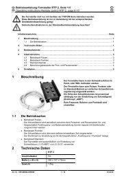
4.2 Rear view<br />
Item Symbol Description 0<br />
Figure 4-2<br />
1 7-pole connection socket (digital)<br />
• Control lead for wire <strong>feed</strong> <strong>unit</strong><br />
2 Connecting nipple G¼, shielding gas connection<br />
3 Quick connect coupling (red)<br />
coolant return<br />
4 Connector plug, welding current "+"<br />
<strong>Welding</strong> current connection on wire <strong>feed</strong> <strong>unit</strong><br />
5 Quick connect coupling (blue)<br />
coolant supply<br />
6 Machine feet<br />
7 Intermediate hose package strain relief<br />
8 Take up point<br />
For housing arbor, wire <strong>feed</strong> <strong>unit</strong><br />
9 <strong>Wire</strong> spool casing<br />
18<br />
099-004846-EW501<br />
8.01.2014
Machine description – quick overview<br />
Inside view<br />
4.3 Inside view<br />
Item Symbol Description 0<br />
1 <strong>Wire</strong> spool casing<br />
2 <strong>Wire</strong> spool holder<br />
3 Take up point<br />
For housing arbor, wire <strong>feed</strong> <strong>unit</strong><br />
4 <strong>Wire</strong> <strong>feed</strong> <strong>unit</strong><br />
Figure 4-3<br />
5 <strong>Welding</strong> torch function changeover switch (special welding torch required)<br />
Changing over programs or JOBs<br />
Infinite adjustment of welding performance.<br />
6 Protective cap<br />
Cover for the wire <strong>feed</strong> mechanism and other operating elements.<br />
Depending on the machine series, additional stickers with information on the<br />
replacement parts and JOB lists will be located on the inside.<br />
099-004846-EW501<br />
8.01.2014<br />
19
Machine description – quick overview<br />
Machine control – <strong>Operating</strong> elements<br />
4.4 Machine control – <strong>Operating</strong> elements<br />
Figure 4-4<br />
20<br />
099-004846-EW501<br />
8.01.2014
Machine description – quick overview<br />
Machine control – <strong>Operating</strong> elements<br />
Item Symbol Description 0<br />
1 Lid (see chap. "Machine control – concealed operating elements")<br />
2 Push-button, parameter selection left/power-saving mode<br />
<strong>Welding</strong> current<br />
Material thickness<br />
<strong>Wire</strong> <strong>feed</strong> speed<br />
After welding, the values used last are shown from the main program. The<br />
signal light is illuminated.<br />
Enter power-saving mode by pressing the push-button for a longer time.<br />
3 Display, left<br />
<strong>Welding</strong> current, material thickness, wire speed, hold values<br />
4 <strong>Welding</strong> parameter setting, rotary dial<br />
For setting the welding performance and for setting other welding parameters.<br />
5 Select operating mode button<br />
Non-latched<br />
Latched<br />
Signal light lights up in green: Special non-latched<br />
Signal light lights up in red: MIG spot welding<br />
Special latched<br />
6 Dynamics/choke effect button<br />
Arc harder and narrower<br />
Arc softer and wider<br />
7 Button, Select welding type<br />
MIG/MAG standard welding<br />
MIG/MAG pulse arc welding<br />
8 Arc length correction/selection of welding program, rotary dial<br />
• Correction of the arc length from -9.9 V to +9.9 V.<br />
• Selection of welding programs 0 to 15 (not possible if accessory components, such<br />
as program torches, are connected).<br />
9 Display, right<br />
<strong>Welding</strong> voltage, program number<br />
10 Button, Parameter selection (right)<br />
VOLT <strong>Welding</strong> voltage<br />
PROG Program number<br />
kW <strong>Welding</strong> performance display<br />
Gas flow quantity (optional)<br />
099-004846-EW501<br />
8.01.2014<br />
21
Machine description – quick overview<br />
Machine control – <strong>Operating</strong> elements<br />
4.4.1 Machine control – Concealed operating elements<br />
Item Symbol Description 0<br />
Figure 4-5<br />
1 Select welding parameters button<br />
This button is used to select the welding parameters depending on the welding process<br />
and operating mode used.<br />
2 Signal light, gas pre-flow time<br />
Setting range 0.0 s to 20.0 s<br />
3 Signal light, start program (P START )<br />
• <strong>Wire</strong> speed:1% to 200% of the main program P A<br />
• Correction of the arc length -9.9 V to +9.9 V<br />
4 Signal light, start time<br />
Setting range, absolute 0.0 s to 20.0 s (0.1 s increments)<br />
5 Signal light, slope time program P START to main program P A<br />
Setting range 0.0 s to 20.0 s (0.1 s increments)<br />
6 Signal light, main program (P A )<br />
• <strong>Wire</strong> speed WF-min. to WF-max.<br />
• Correction of the arc length -9.9 V to +9.9 V<br />
7 Signal light, dynamics<br />
Setting range -40 to +40<br />
8 Signal light, duration of main program P A<br />
Setting range 0.1 s to 20.0 s (0.1 s increments).<br />
Used e.g. in connection with the super pulse function<br />
9 Signal light, reduced main program (P B )<br />
• <strong>Wire</strong> speed:1% to 200% of the main program P A<br />
• Correction of the arc length -9.9 V to +9.9 V<br />
10 Signal light, duration reduced main program P B<br />
Setting range 0.0 s to 20.0 s (0.1 s increments).<br />
Used e.g. in connection with the super pulse function.<br />
11 Signal light, slope time program P A (or P B ) to end program P END<br />
Setting range 0.0 s to 20.0 s (0.1 s increments)<br />
12 Signal light, end program (P END )<br />
• <strong>Wire</strong> speed:1% to 200% of the main program P A<br />
• Correction of the arc length -9.9 V to +9.9 V<br />
13 Signal light, duration of end program P END<br />
Setting range 0.0 s to 20.0 s (0.1 s increments)<br />
14 Signal light, gas post-flow time<br />
Setting range 0.0 s to 20.0 s<br />
22<br />
099-004846-EW501<br />
8.01.2014
Machine description – quick overview<br />
Machine control – <strong>Operating</strong> elements<br />
Item Symbol Description 0<br />
15 Signal lamp, super pulse function<br />
Lights up when the super pulse function is active.<br />
16 Button, special job<br />
Select the special jobs SP1 to SP3 (JOB 129 to 131)<br />
17 <strong>Wire</strong> inching button<br />
See also “Inching the <strong>Wire</strong> Electrode” chapter<br />
18 Gas test / rinse button<br />
• Gas test: For setting the shielding gas quantity<br />
• Rinse: For rinsing longer hose packages<br />
See also "Shielding Gas Supply" chapter<br />
099-004846-EW501<br />
8.01.2014<br />
23
Design and function<br />
General<br />
5 Design and function<br />
5.1 General<br />
WARNING<br />
Risk of injury from electric shock!<br />
Contact with live parts, e.g. welding current sockets, is potentially fatal!<br />
• Follow safety <strong>instructions</strong> on the opening pages of the operating <strong>instructions</strong>.<br />
• Commissioning may only be carried out by persons who have the relevant expertise of<br />
working with arc welding machines!<br />
• Connection and welding leads (e.g. electrode holder, welding torch, workpiece lead,<br />
interfaces) may only be connected when the machine is switched off!<br />
CAUTION<br />
Insulate the arc welder from welding voltage!<br />
Not all active parts of the welding current circuit can be shielded from direct contact. To<br />
avoid any associated risks it is vital for the welder to adhere to the relevant safety<br />
regulations. Even low voltages can cause a shock and lead to accidents.<br />
• Wear dry and undamaged protective clothing (shoes with rubber soles/welder's gloves<br />
made from leather without any studs or braces)!<br />
• Avoid direct contact with non-insulated connection sockets or connectors!<br />
• Always place torches and electrode holders on an insulated surface!<br />
Risk of burns on the welding current connection!<br />
If the welding current connections are not locked, connections and leads heat up and<br />
can cause burns, if touched!<br />
• Check the welding current connections every day and lock by turning in clockwise direction,<br />
if necessary.<br />
Risk of injury due to moving parts!<br />
The wire <strong>feed</strong>ers are equipped with moving parts, which can trap hands, hair, clothing<br />
or tools and thus injure persons!<br />
• Do not reach into rotating or moving parts or drive components!<br />
• Keep casing covers or protective caps closed during operation!<br />
Risk of injury due to welding wire escaping in an unpredictable manner!<br />
<strong>Welding</strong> wire can be conveyed at very high speeds and, if conveyed incorrectly, may<br />
escape in an uncontrolled manner and injure persons!<br />
• Before mains connection, set up the complete wire guide system from the wire spool to the<br />
welding torch!<br />
• Remove the pressure rollers from the wire <strong>feed</strong>er if no welding torch is fitted!<br />
• Check wire guide at regular intervals!<br />
• Keep all casing covers or protective caps closed during operation!<br />
Risk from electrical current!<br />
If welding is carried out alternately using different methods and if a welding torch and<br />
an electrode holder remain connected to the machine, the open-circuit/welding voltage<br />
is applied simultaneously on all cables.<br />
• The torch and the electrode holder should therefore always be placed on an insulated<br />
surface before starting work and during breaks.<br />
24<br />
099-004846-EW501<br />
8.01.2014
Design and function<br />
Installation<br />
CAUTION<br />
Damage due to incorrect connection!<br />
Accessory components and the power source itself can be damaged by incorrect<br />
connection!<br />
• Only insert and lock accessory components into the relevant connection socket when the<br />
machine is switched off.<br />
• Comprehensive descriptions can be found in the operating <strong>instructions</strong> for the relevant<br />
accessory components.<br />
• Accessory components are detected automatically after the power source is switched on.<br />
Using protective dust caps!<br />
Protective dust caps protect the connection sockets and therefore the machine against<br />
dirt and damage.<br />
• The protective dust cap must be fitted if there is no accessory component being operated<br />
on that connection.<br />
• The cap must be replaced if faulty or if lost!<br />
NOTE<br />
Observe documentation of other system components when connecting!<br />
5.2 Installation<br />
WARNING<br />
Risk of accident due to improper transport of machines that may not be lifted!<br />
Do not lift or suspend the machine! The machine can fall down and cause injuries! The<br />
handles and brackets are suitable for transport by hand only!<br />
• The machine may not be lifted by crane or suspended!<br />
• Depending on machine type, equipment for lifting by crane or use while suspended is<br />
available as a retrofitting option (see chapter "Accessories").<br />
CAUTION<br />
Installation site!<br />
The machine must not be operated in the open air and must only be set up and<br />
operated on a suitable, stable and level base!<br />
• The operator must ensure that the ground is non-slip and level, and provide sufficient<br />
lighting for the place of work.<br />
• Safe operation of the machine must be guaranteed at all times.<br />
099-004846-EW501<br />
8.01.2014<br />
25
Design and function<br />
<strong>Welding</strong> torch cooling system<br />
5.3 <strong>Welding</strong> torch cooling system<br />
5.3.1 General<br />
CAUTION<br />
Coolant mixtures!<br />
Mixtures with other liquids or the use of unsuitable coolants result in material damage<br />
and renders the manufacturer's warranty void!<br />
• Only use the coolant described in this manual (overview of coolants).<br />
• Do not mix different coolants.<br />
• When changing the coolant, the entire volume of liquid must be changed.<br />
Insufficient frost protection in the welding torch coolant!<br />
Depending on the ambient conditions, different liquids are used for cooling the welding<br />
torch (see overview of coolants).<br />
Coolants with frost protection (KF 37E or KF 23E) must be checked regularly to ensure<br />
that the frost protection is adequate to prevent damage to the machine or the accessory<br />
components.<br />
• The coolant must be checked for adequate frost protection with the TYP 1 frost protection<br />
tester (see accessories).<br />
• Replace coolant as necessary if frost protection is inadequate!<br />
NOTE<br />
The disposal of coolant must be carried out according to official regulations and<br />
observing the relevant safety data sheets (German waste code number: 70104)!<br />
• Coolant must not be disposed of together with household waste.<br />
• Coolant must not be discharged into the sewerage system.<br />
• Recommended cleaning agent: water, if necessary with cleaning agent added.<br />
5.3.2 List of coolants<br />
The following coolants may be used (for item nos., please see the Accessories chapter):<br />
Coolant<br />
Temperature range<br />
KF 23E (Standard) -10 °C to +40 °C<br />
KF 37E -20 °C to +10 °C<br />
DKF 23E (for plasma machines) 0 °C to +40 °C<br />
26<br />
099-004846-EW501<br />
8.01.2014
5.4 Notes on the installation of welding current leads<br />
NOTE<br />
Design and function<br />
Notes on the installation of welding current leads<br />
Incorrectly installed welding current leads can cause faults in the arc (flickering).<br />
A<br />
B<br />
C<br />
D<br />
E<br />
Install welding lead and hose package in parallel and as close together as possible.<br />
Keep the welding lead and hose packages of each welding machine separate, with an<br />
installation distance of at least 15 cm!<br />
Fully unroll welding current leads, torch hose packages and intermediate hose<br />
packages. Avoid loops!<br />
Use an individual welding lead to the workpiece for each welding machine!<br />
Connect the work clamp close to the welding point.<br />
Always keep leads as short as possible!<br />
Figure 5-1<br />
Item Symbol Description 0<br />
1 <strong>Welding</strong> machine<br />
2 <strong>Wire</strong> <strong>feed</strong> <strong>unit</strong><br />
3 Workpiece<br />
099-004846-EW501<br />
8.01.2014<br />
27
Design and function<br />
Intermediate hose package connection<br />
5.5 Intermediate hose package connection<br />
Item Symbol Description 0<br />
1 Power source<br />
2 Intermediate hose package<br />
Figure 5-2<br />
3 7-pole connection socket (digital)<br />
• Control lead for wire <strong>feed</strong> <strong>unit</strong><br />
4 Connecting nipple G¼, shielding gas connection<br />
5 Quick connect coupling (red)<br />
coolant return<br />
6 Connector plug, welding current "+"<br />
<strong>Welding</strong> current connection on wire <strong>feed</strong> <strong>unit</strong><br />
7 Quick connect coupling (blue)<br />
coolant supply<br />
8 Intermediate hose package strain relief<br />
• Insert the end of the hose package through the strain relief of the hose package and lock by turning to<br />
the right.<br />
• Push the welding current cable socket onto the “welding current connecting plug” and lock by turning<br />
to the right.<br />
• Connect crown nut of the shielding gas line to the G¼“ connecting nipple.<br />
• Insert cable plug on the control lead into the 7-pole connection socket and secure with crown nut (the<br />
plug can only be inserted into the connection socket in one position).<br />
• Lock connecting nipples of the cooling water tubes into the corresponding quick connect couplings:<br />
Return line red to quick connect coupling, red (coolant return) and<br />
supply line blue to quick connect coupling, blue (coolant supply).<br />
28<br />
099-004846-EW501<br />
8.01.2014
Design and function<br />
Shielding gas supply (shielding gas cylinder for welding machine)<br />
5.6 Shielding gas supply (shielding gas cylinder for welding machine)<br />
5.6.1 Gas test<br />
• Slowly open the gas cylinder valve.<br />
• Open the pressure regulator.<br />
• Switch on the power source at the main switch.<br />
• Initiate gas test function on the machine control.<br />
• Set the relevant gas quantity for the application on the pressure regulator.<br />
• The gas test is triggered on the machine control by pressing the button briefly.<br />
Shielding gas flows for around 25 seconds or until the button is pressed again.<br />
5.6.2 “Rinse hose package” function<br />
<strong>Operating</strong><br />
Element<br />
Action Result<br />
5 s<br />
Select rinse hose package.<br />
Shielding gas flows continuously until the Gas Test button is pressed<br />
again.<br />
5.6.3 Setting the shielding gas quantity<br />
<strong>Welding</strong> process<br />
Recommended shielding gas quantity<br />
MAG welding<br />
MIG brazing<br />
MIG welding (aluminium)<br />
<strong>Wire</strong> diameter x 11.5 = l/min<br />
<strong>Wire</strong> diameter x 11.5 = l/min<br />
<strong>Wire</strong> diameter x 13.5 = l/min (100 % argon)<br />
Helium-rich gas mixtures require a higher gas volume!<br />
The table below can be used to correct the gas volume calculated where necessary:<br />
Shielding gas<br />
Factor<br />
75% Ar/25% He 1.14<br />
50% Ar/50% He 1.35<br />
25% Ar/75% He 1.75<br />
100% He 3.16<br />
NOTE<br />
Incorrect shielding gas setting!<br />
If the shielding gas setting is too low or too high, this can introduce air to the weld pool<br />
and may cause pores to form.<br />
• Adjust the shielding gas quantity to suit the welding task!<br />
099-004846-EW501<br />
8.01.2014<br />
29
Design and function<br />
MIG/MAG welding<br />
5.7 MIG/MAG welding<br />
5.7.1 <strong>Welding</strong> torch connection<br />
CAUTION<br />
Equipment damage due to improperly connected coolant lines!<br />
If the coolant lines are not connected or a gas-cooled welding torch is used, the coolant<br />
circuit is interrupted and equipment damage can occur.<br />
• Connect all coolant lines correctly!<br />
• When using a gas-cooled welding torch, add a tube bridge to the coolant circuit (see<br />
chapter “Accessories”).<br />
NOTE<br />
Fault with the wire guide!<br />
On delivery, the central connector is fitted with a capillary tube for welding torches with<br />
spiral guides. Conversion is necessary if a welding torch with a plastic core is used!<br />
<strong>Welding</strong> torch with plastic core:<br />
• use with guide tube!<br />
<strong>Welding</strong> torch with spiral guide:<br />
• use with capillary tube!<br />
Depending on the wire electrode diameter or type, either a spiral guide or plastic core with the<br />
correct inner diameter has to be inserted in the torch!<br />
Recommendation:<br />
• Use a spiral guide to weld hard, unalloyed wire electrodes (steel).<br />
• Use a plastic core to weld or braze soft, high-alloy wire electrodes or aluminium materials.<br />
Preparation for connecting welding torches with a plastic core:<br />
• Push forward the capillary tube on the wire <strong>feed</strong> side in the direction of the central connector and<br />
remove it there.<br />
• Slide plastic core guide tube off the central connector.<br />
• Carefully insert the central plug for the welding torch, with the still oversized plastic liner, into the<br />
central connector and screw together with crown nut.<br />
• Use a suitable tool to cut off the plastic liner just before the wire <strong>feed</strong> roller, making sure not to pinch it.<br />
• Unfasten and remove the central plug on the welding torch.<br />
• Cleanly remove the burr from the separated end of the plastic core!<br />
Preparation for connecting welding torches with a spiral guide:<br />
• Check that the capillary tube is correctly positioned in relation to the central connector!<br />
30<br />
099-004846-EW501<br />
8.01.2014
Design and function<br />
MIG/MAG welding<br />
Figure 5-3<br />
Item Symbol Description 0<br />
1 <strong>Welding</strong> torch<br />
2 <strong>Welding</strong> torch hose package<br />
3 <strong>Welding</strong> torch connection (Euro or Dinse torch connector)<br />
<strong>Welding</strong> current, shielding gas and torch trigger integrated<br />
4 19-pole connection socket (analogue)<br />
For connecting analogue accessory components (remote control, welding torch control<br />
lead, etc.)<br />
5 Quick connect coupling (blue)<br />
coolant supply<br />
6 Quick connect coupling (red)<br />
coolant return<br />
• Insert the central plug for the welding torch into the central connector and screw together with crown<br />
nut.<br />
• Lock connecting nipples of the cooling water tubes into the corresponding quick connect couplings:<br />
Return line red to quick connect coupling, red (coolant return) and<br />
supply line blue to quick connect coupling, blue (coolant supply).<br />
Only MIG/MAG torches with special functions (additional control lead):<br />
• Insert the torch control lead plug into the 19-pole connection socket and lock in place.<br />
099-004846-EW501<br />
8.01.2014<br />
31
Design and function<br />
MIG/MAG welding<br />
5.7.2 <strong>Wire</strong> <strong>feed</strong><br />
5.7.2.1 Open the protective flap of the wire <strong>feed</strong>er<br />
CAUTION<br />
To perform the following steps, the protective flap of the wire <strong>feed</strong>er needs to be<br />
opened. Make sure to close the protective flap again before starting to work.<br />
• Unlock and open protective flap.<br />
5.7.2.2 Inserting the wire spool<br />
CAUTION<br />
Risk of injury due to incorrectly secured wire spool.<br />
If the wire spool is not secured properly, it may come loose from the wire spool holder<br />
and fall to the ground, causing damage to the machine and injuries.<br />
• Securely fasten the wire spool to the wire spool holder using the knurled nut.<br />
• Before you start working, always check the wire spool is securely fastened.<br />
NOTE<br />
Standard D300 wire spool holder can be used. Adapters (see accessories) are required<br />
when using standardised basket coils (DIN 8559).<br />
Item Symbol Description 0<br />
1 Carrier pin<br />
For fixing the wire spool<br />
2 Knurled nut<br />
For fixing the wire spool<br />
• Loosen knurled nut from spool holder.<br />
Figure 5-4<br />
• Fix welding wire reel onto the spool holder so that the carrier pin locks into the spool bore.<br />
• Fasten wire spool using knurled nut.<br />
32<br />
099-004846-EW501<br />
8.01.2014
Design and function<br />
MIG/MAG welding<br />
5.7.2.3 Changing the wire <strong>feed</strong> rollers<br />
NOTE<br />
Unsatisfactory welding results due to faulty wire <strong>feed</strong>ing!<br />
<strong>Wire</strong> <strong>feed</strong> rollers must be suitable for the diameter of the wire and the material.<br />
• Check the roller label to verify that the rollers are suitable for the wire diameter.<br />
Turn or change if necessary!<br />
• use V-groove rollers with for steel wires and other hard wires,<br />
• use U-groove rollers for aluminium wires and other soft, alloyed wires.<br />
• Slide new drive rollers into place so that the diameter of the wire used is visible on the drive roller.<br />
• Screw the drive rollers in place with knurled screws.<br />
Figure 5-5<br />
099-004846-EW501<br />
8.01.2014<br />
33
Design and function<br />
MIG/MAG welding<br />
5.7.2.4 Inching the wire electrode<br />
CAUTION<br />
Risk of injury due to moving parts!<br />
The wire <strong>feed</strong>ers are equipped with moving parts, which can trap hands, hair, clothing<br />
or tools and thus injure persons!<br />
• Do not reach into rotating or moving parts or drive components!<br />
• Keep casing covers or protective caps closed during operation!<br />
Risk of injury due to welding wire escaping in an unpredictable manner!<br />
<strong>Welding</strong> wire can be conveyed at very high speeds and, if conveyed incorrectly, may<br />
escape in an uncontrolled manner and injure persons!<br />
• Before mains connection, set up the complete wire guide system from the wire spool to the<br />
welding torch!<br />
• Remove the pressure rollers from the wire <strong>feed</strong>er if no welding torch is fitted!<br />
• Check wire guide at regular intervals!<br />
• Keep all casing covers or protective caps closed during operation!<br />
Risk of injury due to welding wire escaping from the welding torch!<br />
The welding wire can escape from the welding torch at high speed and cause bodily<br />
injury including injuries to the face and eyes!<br />
• Never direct the welding torch towards your own body or towards other persons!<br />
CAUTION<br />
Extensive wear due to incorrect contact pressure!<br />
Incorrect contact pressure will cause extensive wear of the wire <strong>feed</strong> rollers!<br />
• With the adjusting nuts of the pressure <strong>unit</strong>s set the contact pressure so that the wire<br />
electrode is conveyed but will still slip through if the wire spool jams.<br />
• Set the contact pressure of the front rollers (in wire <strong>feed</strong> direction) to a higher value!<br />
34<br />
099-004846-EW501<br />
8.01.2014
Design and function<br />
MIG/MAG welding<br />
Item Symbol Description 0<br />
1 Pressure <strong>unit</strong><br />
2 Clamping <strong>unit</strong><br />
3 Knurled nut<br />
4 Pressure roller<br />
5 <strong>Wire</strong> <strong>feed</strong> nipple<br />
6 Guide tube<br />
7 Drive rollers<br />
8 "Undetachable" knurled screws<br />
Figure 5-6<br />
9 <strong>Wire</strong> <strong>feed</strong> nipple with wire stabiliser<br />
• Extend and lay out the torch hose package.<br />
• Unfasten pressure <strong>unit</strong>s and fold out (clamping <strong>unit</strong>s and pressure rollers will automatically flip<br />
upwards).<br />
• Unwind welding wire carefully from the wire spool and insert through the wire inlet nipple over the<br />
drive roller grooves and the guide pipe into the capillary tube and Teflon core using guide pipe.<br />
• Press the clamping element with the pressure roller back downwards and fold the wire <strong>unit</strong>s back up<br />
again (wire electrode should be in the groove on the drive roller).<br />
• Set the contact pressure with the adjusting nuts of the pressure <strong>unit</strong>.<br />
• Press the wire inching button until the wire electrode projects out of the welding torch.<br />
Automatic inching stop<br />
Touch the welding torch against the workpiece during inching. Inching of the welding wire will stop as<br />
soon it touches the workpiece.<br />
099-004846-EW501<br />
8.01.2014<br />
35
Design and function<br />
MIG/MAG welding<br />
5.7.2.5 Spool brake setting<br />
Item Symbol Description 0<br />
Figure 5-7<br />
1 Allen screw<br />
Securing the wire spool retainer and adjustment of the spool brake<br />
• Tighten the Allen screw (8 mm) in the clockwise direction to increase the braking effect.<br />
NOTE<br />
Tighten the spool brake until the wire spool no longer turns when the wire <strong>feed</strong> motor stops but<br />
without it jamming during operation!<br />
36<br />
099-004846-EW501<br />
8.01.2014
Design and function<br />
MIG/MAG welding<br />
5.7.3 Definition of MIG/MAG welding tasks<br />
This machine range features simple operation with a very wide range of functions.<br />
• Various JOBs (i.e. welding tasks consisting of welding process, material type, wire diameter and<br />
shielding gas type) have been pre-defined (see appendix for a list of JOBs).<br />
• Simple JOB selection using four buttons (material, wire type, wire thickness and shielding gas) on the<br />
welding machine control; illogical combinations are automatically excluded.<br />
• The required process parameters are calculated by the system depending on the operating point<br />
defined (single-dial operation via wire speed rotary dial).<br />
• Additional parameters can be modified as required in the configuration menu on the control or using<br />
the PC300.NET welding parameter software.<br />
5.7.4 <strong>Welding</strong> task selection<br />
NOTE<br />
Selection of a welding task involves the interaction of the controls on the welding<br />
machine and the wire <strong>feed</strong> <strong>unit</strong>. After the basic settings are made on the welding<br />
machine, the operating point and other parameters can be set on the wire <strong>feed</strong> <strong>unit</strong>.<br />
It is only possible to change the 4 basic welding parameters if:<br />
• No welding current is flowing,<br />
• The key switch is set to position "1".<br />
Superpuls<br />
Superpuls<br />
m/min<br />
DY N<br />
m/min<br />
Figure 5-8<br />
099-004846-EW501<br />
8.01.2014<br />
37
Design and function<br />
MIG/MAG welding<br />
<strong>Operating</strong><br />
element<br />
Action<br />
n x<br />
n x<br />
n x<br />
n x<br />
n x<br />
n x<br />
1 x<br />
Result<br />
Select welding process<br />
The signal light indicates the selection.<br />
Select material type<br />
The signal light indicates the selection.<br />
Select wire diameter<br />
The signal light indicates the selection.<br />
Select gas type<br />
The signal light indicates the selection.<br />
Select operating mode<br />
The LED displays the selected operating mode.<br />
Non-latched operation<br />
Latched operation<br />
Green Special non-latched mode<br />
Red Spot operating mode<br />
Special latched mode<br />
Select welding type<br />
The signal light indicates the selection.<br />
Standard MIG/MAG welding<br />
Pulse arc MIG/MAG welding<br />
Switch superpulses on or off<br />
The signal light indicates the selection.<br />
<strong>Operating</strong> point is set using the wire speed previously set<br />
Arc length correction setting<br />
Select Dynamics welding parameter<br />
Dynamic comes on.<br />
Dynamics setting<br />
Arc harder and narrower<br />
Arc softer and wider<br />
38<br />
099-004846-EW501<br />
8.01.2014
Design and function<br />
MIG/MAG welding<br />
5.7.4.1 Burn-back<br />
NOTE<br />
Prevents fusing of the wire electrode in the weld pool.<br />
Back-burn set too high:<br />
• Large ball formation of the wire electrode (poor re-ignition)<br />
• <strong>Wire</strong> electrode sticks in the gas nozzle.<br />
Back-burn set too low:<br />
• <strong>Wire</strong> electrode sticks in the weld pool.<br />
<strong>Welding</strong> machine<br />
<strong>Operating</strong><br />
element<br />
Action Result Display<br />
1 x<br />
n x<br />
Select program sequence mode<br />
Select "RUECK" parameter using the<br />
and<br />
"Down" buttons (left)<br />
"Up"<br />
Program steps<br />
RUECK 2-500<br />
n x<br />
Adjust the selected parameter using the<br />
and "Down" buttons (right)<br />
"Up"<br />
RUECK 2-500<br />
3 x<br />
Machine returns to Display mode<br />
<strong>Wire</strong> <strong>feed</strong> <strong>unit</strong><br />
ENTER<br />
EXIT<br />
3 s<br />
3 s<br />
m/min<br />
Figure 5-9<br />
099-004846-EW501<br />
8.01.2014<br />
39
Design and function<br />
MIG/MAG welding<br />
5.7.5 MIG/MAG operating point<br />
The operating point (welding output) is specified using the principle of MIG/MAG one-dial operation, i.e.<br />
the user need only specify the operating point by setting the required wire speed, for example, and the<br />
digital system will calculate the optimum values for welding current and voltage (operating point).<br />
The operating point setting can also be specified using the accessory components such as the remote<br />
control, welding torch, etc.<br />
5.7.5.1 Selecting the display <strong>unit</strong><br />
The operating point (welding performance) can be displayed as the welding current, material thickness or<br />
wire speed.<br />
On the welding machine using control M3.19<br />
<strong>Operating</strong><br />
element<br />
Action Result<br />
n x<br />
On the wire <strong>feed</strong> <strong>unit</strong> using control M3.70<br />
<strong>Operating</strong><br />
element<br />
Action Result<br />
n x<br />
Switching the display between:<br />
<strong>Welding</strong> current,<br />
Material thickness,<br />
<strong>Wire</strong> speed<br />
Switching the display between:<br />
<strong>Welding</strong> current<br />
Material thickness,<br />
<strong>Wire</strong> speed<br />
Example application<br />
You are welding aluminium (material= AlMg, gas= Ar 100%, wire diameter= 1.2 mm and 5 mm material<br />
thickness), you don’t have any specifications and do not know the required settings, e.g. for the wire<br />
speed.<br />
Switch to the material thickness display. Set the operating point to 5 mm.<br />
This corresponds to a wire speed of 8.4 m/min, for example.<br />
5.7.5.2 <strong>Operating</strong> point setting using material thickness<br />
NOTE<br />
The settings are made on the wire <strong>feed</strong> <strong>unit</strong> control.<br />
The process of setting the operating point by means of the panel thickness parameter is described as an<br />
example below.<br />
<strong>Operating</strong><br />
element<br />
Action Result Display<br />
Increase or reduce welding performance via the<br />
panel thickness parameter.<br />
Display example: 5.0 mm<br />
40<br />
099-004846-EW501<br />
8.01.2014
Design and function<br />
MIG/MAG welding<br />
5.7.5.3 Arc length correction setting<br />
NOTE<br />
The settings are made on the wire <strong>feed</strong> <strong>unit</strong> control.<br />
<strong>Operating</strong><br />
Element<br />
Action Result Display<br />
Arc length correction setting<br />
Parameter selected<br />
is displayed<br />
5.7.5.4 Accessory components for operating point setting<br />
The operating point can also be set with various accessory components such as<br />
• remote controls<br />
• special torches<br />
• PC software<br />
• robot and industrial bus interfaces (optional mechanised welding interface required – not possible for<br />
all machines in this series!)<br />
You will find an overview of accessory components in the "Accessories" chapter. See the operating<br />
<strong>instructions</strong> for the machine in question for a more detailed description of the individual machines and<br />
their functions.<br />
5.7.6 MIG/MAG welding data display<br />
To the left and right of the control displays are the "Parameter selection" buttons ( ). They are used to<br />
select welding parameters to be displayed.<br />
Each press of the button advances the display to the next parameter (LEDs next to the button indicate the<br />
selection). After the last parameter is reached, the system starts again from the beginning.<br />
The display shows:<br />
• Nominal values (before welding)<br />
• Actual values (during welding)<br />
• Hold values (after welding)<br />
Figure 5-10<br />
Parameter Nominal values Actual values Hold values<br />
<strong>Welding</strong> current <br />
Material thickness <br />
<strong>Wire</strong> <strong>feed</strong> speed <br />
<strong>Welding</strong> voltage <br />
<strong>Welding</strong> performance <br />
When settings are changed (e.g. wire <strong>feed</strong> speed) the display immediately switches to nominal<br />
value setting.<br />
099-004846-EW501<br />
8.01.2014<br />
41
Design and function<br />
MIG/MAG welding<br />
5.7.7 Conventional MIG/MAG <strong>Welding</strong> (GMAW non synergic)<br />
• With wire-<strong>feed</strong> speeds less than 8 m/min select JOB 188.<br />
• With wire-<strong>feed</strong> speeds over 8 m/min select JOB 187.<br />
You can only change the JOB number when no welding current is flowing.<br />
<strong>Operating</strong><br />
element<br />
Action Result Display<br />
1 x<br />
Select JOB list.<br />
(LED<br />
is on)<br />
Set JOB number.<br />
Wait 3 s until the setting has been applied.<br />
5.7.7.1 Setting the operating point (welding output)<br />
The operating point (welding performance) is set using the wire-<strong>feed</strong> speed and the welding voltage.<br />
<strong>Operating</strong><br />
element<br />
Action<br />
n x<br />
Result<br />
Switch the display between:<br />
<strong>Welding</strong> current (display of actual and hold value only)<br />
Material thickness<br />
<strong>Wire</strong> speed<br />
After welding, the values used last<br />
from the main program are displayed.<br />
The settings are made using the rotary dials for welding parameter setting and arc length correction.<br />
<strong>Operating</strong><br />
element<br />
Action<br />
Result<br />
Increase or reduce the welding performance via the wire speed<br />
parameter.<br />
JOB 188: from 1-8 m/min<br />
JOB 187: from 8-21 m/min<br />
<strong>Operating</strong><br />
element<br />
Action<br />
Result<br />
Set the welding voltage.<br />
Setting range:<br />
-9.9 V-9.9 V<br />
42<br />
099-004846-EW501<br />
8.01.2014
Design and function<br />
MIG/MAG welding<br />
5.7.8 forceArc / forceArc puls<br />
Heat-reduced, directionally stable and powerful arc with deep penetration for the upper power range.<br />
Figure 5-11<br />
• Smaller included angle due to deep penetration and directionally stable arc<br />
• Excellent root and sidewall fusion<br />
• Secure welding also with very long stick-outs<br />
• Reduced undercuts<br />
• Un-, low- and high-alloyed steels as well as high-tensile fine-grained building steels<br />
• Manual and automated applications<br />
forceArc welding from:<br />
<strong>Wire</strong> Ø (mm)<br />
0.8 1 1.2 1.6<br />
Material Gas JOB JOB JOB JOB<br />
Steel Ar 91–99% 190 17.0 254 12.0 255 9.5 256 7.0<br />
Ar 80–90% 189 17.0 179 12.0 180 9.5 181 6.0<br />
CrNi Ar 91–99% - - 251 12.0 252 12.0 253 6.0<br />
You can make use of these properties after selecting the forceArc process (see the "Selecting a<br />
MIG/MAG welding task" chapter).<br />
As with pulse arc welding, it is important to make sure of a good welding current connection.<br />
• Keep welding current cables as short as possible and ensure that cable cross-sections are adequate!<br />
• Fully unroll welding current cables, torche hose packages and, if applicable, intermediate hose<br />
packages. Avoid loops!<br />
• Use welding torches, preferably water-cooled, that are suitable for the higher power range.<br />
• Use welding wire with adequate copper coating when welding steel. The wire spool should have layer<br />
spooling.<br />
NOTE<br />
Unstable arc!<br />
<strong>Welding</strong> current cables that are not fully unrolled can cause faults in the arc (flickering).<br />
• Fully unroll welding current cables, torch hose packages and, if applicable, intermediate<br />
hose packages. Avoid loops!<br />
099-004846-EW501<br />
8.01.2014<br />
43
Design and function<br />
MIG/MAG welding<br />
5.7.9 rootArc/rootArc puls<br />
Short arc with easy weld modelling capabilities for effortless gap bridging and positional welding.<br />
• Reduced spatter compared to standard short arc<br />
• Good root formation and secure sidewall fusion<br />
• Un-alloyed and low-alloy steels<br />
• Manual and automated applications<br />
rootArc welding up to:<br />
Figure 5-12<br />
<strong>Wire</strong> Ø (mm)<br />
0.6 0.8 0.9 1 1.2 1.6<br />
Material Gas JOB JOB JOB JOB JOB JOB<br />
Steel<br />
CO2 - - - - - - 204 7.0 205 5.0 - -<br />
Ar 80–90% - - - - - - 206 8.0 207 6.0 - -<br />
NOTE<br />
Unstable arc!<br />
<strong>Welding</strong> current cables that are not fully unrolled can cause faults in the arc (flickering).<br />
• Fully unroll welding current cables, torch hose packages and, if applicable, intermediate<br />
hose packages. Avoid loops!<br />
44<br />
099-004846-EW501<br />
8.01.2014
Design and function<br />
MIG/MAG welding<br />
5.7.10 MIG/MAG program sequence ("Program steps" mode)<br />
NOTE<br />
Changes to the welding parameters can only be made when the key switch is in<br />
position "1".<br />
5.7.10.1 Selecting the program sequence parameters using wire <strong>feed</strong> <strong>unit</strong> control M3.70<br />
<strong>Operating</strong><br />
Element<br />
Action Result Display<br />
n x<br />
Select parameter in the program sequence<br />
Setting welding parameters<br />
099-004846-EW501<br />
8.01.2014<br />
45
Design and function<br />
MIG/MAG welding<br />
5.7.10.2 MIG/MAG overview of parameters, M3.70<br />
Figure 5-13<br />
Basic Parameters<br />
Item Meaning / Explanation Setting Range<br />
1 Gas pre-flow time 0.0s to 20.0s<br />
2 P START<br />
<strong>Wire</strong> speed, relative<br />
Arc length correction<br />
1% to 200%<br />
-9.9V to +9.9V<br />
3 Duration 0.0s to 20.0s<br />
4 Slope duration from P START to P A 0.0s to 20.0s<br />
5 P A<br />
<strong>Wire</strong> speed, absolute<br />
6 Dynamics -40 to +40<br />
0.1 m/min to 40 m/min<br />
7 Duration (spot time and superpulse) 0.01s to 20.0s<br />
8 P B<br />
<strong>Wire</strong> speed, relative<br />
Arc length correction, relative<br />
1% to 200%<br />
-9.9V to +9.9V<br />
9 Duration 0.01s to 20.0s<br />
10 Slope duration from P A to P END 0.0s to 20s<br />
11 P END<br />
<strong>Wire</strong> speed, relative<br />
Arc length correction<br />
1% to 200%<br />
-9.9V to +9.9V<br />
12 Duration (superpulse) 0.0s to 20s<br />
13 Gas post-flow time 0.0s to 20s<br />
14 Superpulses On / Off<br />
46<br />
099-004846-EW501<br />
8.01.2014
Design and function<br />
MIG/MAG welding<br />
5.7.11 Main program A mode<br />
<strong>Operating</strong><br />
element<br />
Action Result Display<br />
n x<br />
Change welding data display over to program<br />
display.<br />
(LED PROG is on)<br />
Select program number.<br />
Display example: Program "1".<br />
n x<br />
Select program sequence parameter<br />
"Main program (P A )".<br />
(LED is on)<br />
Set wire speed.<br />
(Absolute value)<br />
1 x<br />
Set arc length correction.<br />
Display example: "-0.8 V" correction<br />
(Setting range: -9.9 V to +9.9 V)<br />
Select "Dynamic" program sequence parameter.<br />
(LED is on)<br />
Set dynamic. (Setting range 40 to -40)<br />
40: Arc hard and narrow.<br />
-40: Arc soft and wide.<br />
NOTE<br />
Changes to the welding parameters can only be made when the key switch is in<br />
position "1".<br />
5.7.12 MIG/MAG automatic cut-out<br />
NOTE<br />
The welding machine ends the ignition process or the welding process with an<br />
• ignition fault (no welding current flows within 5 s after the start signal)<br />
• arc interruption (arc is intrerupted for longer than 5 s)<br />
099-004846-EW501<br />
8.01.2014<br />
47
Design and function<br />
MIG/MAG welding<br />
5.7.13 Standard MIG/MAG torch<br />
The MIG welding torch trigger is essentially used to start and stop the welding process.<br />
<strong>Operating</strong> elements<br />
Functions<br />
Torch trigger • Start/stop welding<br />
Other functions are also possible by tapping the torch trigger, depending on the machine type<br />
and control configuration:<br />
• Change over between welding programs (see "Program changeover with standard torches (P8)"<br />
chapter).<br />
• Change over between pulse and standard welding in the special latched operating mode.<br />
• Switching between wire <strong>feed</strong> <strong>unit</strong>s in dual operation mode (see chapter "M3.70/M3.71 machine<br />
controls – special parameters, single or double operation setting (P10)")<br />
5.7.14 MIG/MAG special-torches<br />
Function specifications and more indepth information can be found in the operating manual for<br />
the relevant welding torch!<br />
5.7.14.1 Program- and Up- / down operation<br />
Figure 5-14<br />
Item Symbol Description 0<br />
1 <strong>Welding</strong> torch function changeover switch (special welding torch required)<br />
Changing over programs or JOBs<br />
Infinite adjustment of welding performance.<br />
48<br />
099-004846-EW501<br />
8.01.2014
Design and function<br />
MIG/MAG welding<br />
5.7.14.2 MIG/MAG Push/Pull welding torch<br />
The most important requirement for the greatest degree of efficiency and weld seam quality is the smooth<br />
conveyance of the wire electrode. This is particularly problematic when:<br />
• Longer tube packages are used,<br />
• <strong>Wire</strong> electrodes have poor sliding properties,<br />
• <strong>Wire</strong> electrodes have poor bending strength and<br />
• An especially even wire outlet speed is required.<br />
In this process, additional conveying aids in the torch produce significant improvements in comparison<br />
with pure <strong>feed</strong> wire conveyors. In addition to a pushing wire <strong>feed</strong> (PUSH) in the power source / wire <strong>feed</strong><br />
case, a pulling wire <strong>feed</strong> (PULL) is used in the torch.<br />
The two <strong>feed</strong> motors are synchronised by a current regulator.<br />
<strong>Welding</strong> torches without potentiometers<br />
<strong>Operating</strong> elements Functions<br />
1 torch trigger <strong>Welding</strong> On/Off<br />
Push/Pull torch with one potentiometer<br />
NOTE<br />
Changeover switch in WF <strong>unit</strong> to "Up / Down" (see "Internal operating elements" chapter)<br />
Infinitely adjustable setting of welding performance (Up/Down function)<br />
<strong>Operating</strong> elements Functions<br />
1 torch trigger <strong>Welding</strong> On/Off<br />
1 rotary dial Infinite adjustment of the wire speed<br />
5.7.14.3 Pin assignment<br />
No potentiometers<br />
With potentiometer for wire<br />
<strong>feed</strong>ing speed<br />
Figure 5-15<br />
With potentiometers for wire<br />
<strong>feed</strong>ing speed and arc length<br />
correction<br />
099-004846-EW501<br />
8.01.2014<br />
49
Design and function<br />
MIG/MAG welding<br />
5.7.14.4 Switching between Push/Pull and intermediate drive<br />
DANGER<br />
Do not carry out any unauthorised repairs or modifications!<br />
To avoid injury and equipment damage, the <strong>unit</strong> must only be repaired or modified by<br />
specialist, skilled persons!<br />
The warranty becomes null and void in the event of unauthorised interference.<br />
• Appoint only skilled persons for repair work (trained service personnel)!<br />
CAUTION<br />
Test!<br />
Before re-commissioning, it is essential that an "inspection and test during operation"<br />
is carried out conforming to IEC / DIN EN 60974-4 "Arc welding devices - inspection and<br />
testing during operation"!<br />
• For detailed <strong>instructions</strong>, please see the standard operating <strong>instructions</strong> for the welding<br />
machine.<br />
The plugs are located directly on the M3.7x printed circuit board.<br />
Plug Function<br />
on X24 Operation with Push/Pull welding torch (factory setting)<br />
on X23 Operation with intermediate drive<br />
50<br />
099-004846-EW501<br />
8.01.2014
Design and function<br />
MIG/MAG welding<br />
5.7.15 Expert menu (MIG/MAG)<br />
The expert menu includes functions and parameters which are either not set on the machine control, or<br />
which do not require regular setting.<br />
5.7.15.1 Selection<br />
NOTE<br />
ENTER (Enter the menu)<br />
• Keep the "welding parameters" push-button pressed for 3 s.<br />
NAVIGATION (Navigate the menu)<br />
• Select parameters by pressing the "welding parameters" push-button.<br />
• Set or change the parameters by turning the "welding parameter setting" rotary knob.<br />
EXIT (Exit the menu)<br />
• After 3 s, the machine will return automatically to the ready-to-operate status.<br />
ENTER<br />
3 s<br />
NAVIGATION<br />
EXIT<br />
3 s<br />
m/min<br />
Figure 5-16<br />
099-004846-EW501<br />
8.01.2014<br />
51
Design and function<br />
MIG/MAG welding<br />
Display<br />
Setting/selection<br />
Correct wire burn-back (setting range 0–499)<br />
If too high a value is set, a large ball will form at the tip of the wire electrode (bad reignition)<br />
or the wire electrode sticks to the contact tip. If too low a value is set, the wire<br />
electrode sticks to the weld pool.<br />
• Increase value > increase wire burn-back<br />
• Decrease value > decrease wire burn-back<br />
Setting JOB-dependent program limit/n-cycle<br />
The JOB-dependent program limit allows you to limit the number of programs that can be<br />
selected in the selected JOB to (2...9). This option can be set individually per JOB. In<br />
addition, a legacy option to set a "global program limit" is also available. To set this<br />
option use special parameter P4. This setting is then applied to all JOBs for which no<br />
JOB-dependent program limit has been set (see the special parameters description).<br />
You can also use the "Special latched (n-cycle)" operating mode if special parameter 8 is<br />
set to 2. In this case (JOB-dependent program switching activated, special parameter<br />
8 = 2, special latched) you can switch to the next program by tapping the torch trigger in<br />
the main program (see the special parameters description).<br />
1 No JOB-dependent program limit<br />
2–9 JOB-dependent program limit for max. selectable programs.<br />
Change welding process (process switching)<br />
With this function activated the welding process switches from standard arc welding to<br />
pulse arc welding. Switching is effected by either tapping the torch trigger (special<br />
latched) or by activating the superPuls function (switch between program P A and P B ).<br />
on Function activated.<br />
off Function deactivated.<br />
Pulse arc welding process (program P START )<br />
The pulse arc welding process can be activated in the start program (P START ) with the<br />
special non-latched and special latched operating modes.<br />
on Function activated.<br />
off Function deactivated.<br />
Pulse arc welding process (program P END )<br />
The pulse arc welding process can be activated in the end program (P END ) with the<br />
special non-latched and special latched operating modes.<br />
on Function activated.<br />
off Function deactivated.<br />
Ignition type (MIG/MAG)<br />
Application: Low-spatter ignition, e.g. for aluminium and chrome/nickel materials.<br />
0 = Traditional arc ignition<br />
1 = Arc ignition with wire return for push/pull applications<br />
2 = Arc ignition with wire return for non-push/pull applications<br />
52<br />
099-004846-EW501<br />
8.01.2014
Design and function<br />
TIG welding<br />
5.8 TIG welding<br />
5.8.1 <strong>Welding</strong> torch connection<br />
NOTE<br />
TIG welding torches to be connected to a Euro torch connector are available in two<br />
versions:<br />
• TIG combi welding torches are connected to the Euro torch connector of the wire <strong>feed</strong>er<br />
and to the (-) welding current plug of the power source.<br />
• TIG welding torches of the EZA version are connected to the Euro torch connector of the<br />
wire <strong>feed</strong>er only. To do so, the welding current lead of the intermediate hose package must<br />
be connected to the (-) welding current connection at the rear of the <strong>unit</strong>!<br />
Item Symbol Description 0<br />
1 <strong>Welding</strong> torch<br />
Figure 5-17<br />
2 <strong>Welding</strong> torch hose package<br />
3 <strong>Welding</strong> torch connection (Euro or Dinse torch connector)<br />
<strong>Welding</strong> current, shielding gas and torch trigger integrated<br />
4 Quick connect coupling (blue)<br />
coolant supply<br />
5 Quick connect coupling (red)<br />
coolant return<br />
6 "-" welding current connection socket<br />
• TIG welding: <strong>Welding</strong> current connection for welding torch<br />
7 Power source<br />
099-004846-EW501<br />
8.01.2014<br />
53
Design and function<br />
TIG welding<br />
• Insert the central plug for the welding torch into the central connector and screw together with crown<br />
nut.<br />
• Insert the welding current plug of the combi welding torch into the (-) welding current connection<br />
socket and lock into place by turning to the right (only in case of a separate welding current<br />
connection).<br />
• Lock connecting nipples of the cooling water tubes into the corresponding quick connect couplings:<br />
Return line red to quick connect coupling, red (coolant return) and<br />
supply line blue to quick connect coupling, blue (coolant supply).<br />
5.8.2 <strong>Welding</strong> task selection<br />
NOTE<br />
Selection of a welding task involves the interaction of the controls on the welding<br />
machine and the wire <strong>feed</strong> <strong>unit</strong>. After the basic settings are made on the welding<br />
machine, the operating point and other parameters can be set on the wire <strong>feed</strong> <strong>unit</strong>.<br />
m/min<br />
Figure 5-18<br />
<strong>Operating</strong><br />
element<br />
Action Result Display<br />
n x<br />
The various welding processes are run through<br />
until the signal light for the required welding<br />
process comes on.<br />
<strong>Welding</strong> current is set<br />
The nominal values<br />
for the welding<br />
current and welding<br />
voltage are<br />
displayed.<br />
Setpoint setting<br />
54<br />
099-004846-EW501<br />
8.01.2014
Design and function<br />
TIG welding<br />
5.8.3 TIG arc ignition<br />
5.8.3.1 Liftarc ignition<br />
Figure 5-19<br />
The arc is ignited on contact with the workpiece:<br />
a) Carefully place the torch gas nozzle and tungsten electrode tip onto the workpiece and press the torch<br />
trigger (liftarc current flowing, regardless of the main current set).<br />
b) Incline the torch over the torch gas nozzle to produce a gap of approx. 2-3 mm between the electrode<br />
tip and the workpiece. The arc ignites and the welding current is increased, depending on the<br />
operating mode set, to the ignition or main current set.<br />
c) Lift off the torch and swivel to the normal position.<br />
Ending the welding process: Release or press the torch trigger depending on the operating mode<br />
selected.<br />
5.8.4 TIG automatic cut-out<br />
NOTE<br />
The welding machine ends the ignition process or the welding process with an<br />
• ignition fault (no welding current flows within 5 s after the start signal)<br />
• arc interruption (arc is intrerupted for longer than 5 s)<br />
099-004846-EW501<br />
8.01.2014<br />
55
Design and function<br />
TIG welding<br />
5.8.5 TIG arc ignition<br />
5.8.5.1 Liftarc ignition<br />
Figure 5-20<br />
The arc is ignited on contact with the workpiece:<br />
a) Carefully place the torch gas nozzle and tungsten electrode tip onto the workpiece and press the torch<br />
trigger (liftarc current flowing, regardless of the main current set).<br />
b) Incline the torch over the torch gas nozzle to produce a gap of approx. 2-3 mm between the electrode<br />
tip and the workpiece. The arc ignites and the welding current is increased, depending on the<br />
operating mode set, to the ignition or main current set.<br />
c) Lift off the torch and swivel to the normal position.<br />
Ending the welding process: Release or press the torch trigger depending on the operating mode<br />
selected.<br />
5.8.6 Pulses, function sequences<br />
5.8.6.1 Explanation of signs and functions<br />
Symbol Meaning<br />
Press torch trigger<br />
Release torch trigger<br />
Tap torch trigger (press briefly and release)<br />
Shielding gas flowing<br />
I<br />
<strong>Welding</strong> output<br />
Gas pre-flows<br />
Gas post-flows<br />
t<br />
P START<br />
P A<br />
P B<br />
P END<br />
tS1<br />
Non-latched<br />
Special, non-latched<br />
Latched<br />
Special, latched<br />
Time<br />
Ignition program<br />
Main program<br />
Reduced main program<br />
End program<br />
Slope duration from PSTART to PA<br />
56<br />
099-004846-EW501<br />
8.01.2014
Design and function<br />
TIG welding<br />
Non-latched mode<br />
Figure 5-21<br />
Selection<br />
• Select non-latched operating mode .<br />
Step 1<br />
• Press and hold torch trigger.<br />
• Shielding gas is expelled (gas pre-flows).<br />
The arc is ignited using liftarc.<br />
• <strong>Welding</strong> current flows with pre-selected setting.<br />
Step 2<br />
• Release torch trigger.<br />
• Arc is extinguished.<br />
• Gas post-flow time elapses.<br />
Special, non-latched<br />
Selection<br />
Figure 5-22<br />
• Select non-latched special mode .<br />
Step 1<br />
• Press and hold torch trigger<br />
• Shielding gas is expelled (gas pre-flows)<br />
The arc is ignited using liftarc.<br />
• <strong>Welding</strong> gas flows with pre-selected setting in start program “P START ”.<br />
• After the “tstart” ignition current time elapses, the welding current rises with the set upslope time “tS1”<br />
to the main program “P A ”.<br />
Step 2<br />
• Release torch trigger.<br />
• The welding current reduces with the downslope time “tSe” to the end program “P END ”.<br />
• After the end current time “end” elapses, the arc will extinguish.<br />
• Gas post-flow time elapses.<br />
099-004846-EW501<br />
8.01.2014<br />
57
Design and function<br />
TIG welding<br />
Latched mode<br />
Selection<br />
• Select latched operating mode .<br />
Step 1<br />
• Press and hold torch trigger<br />
• Shielding gas is expelled (gas pre-flows)<br />
The arc is ignited using liftarc.<br />
• <strong>Welding</strong> current flows with pre-selected setting.<br />
Step 2<br />
• Release torch trigger (no effect)<br />
Step 3<br />
• Press torch trigger (no effect)<br />
Step 4<br />
• Release torch trigger<br />
• Arc is extinguished.<br />
• Gas post-flow time elapses.<br />
Figure 5-23<br />
58<br />
099-004846-EW501<br />
8.01.2014
Design and function<br />
TIG welding<br />
Latched special<br />
Figure 5-24<br />
Selection<br />
• Select latched special mode .<br />
Step 1<br />
• Press and hold torch trigger.<br />
• Shielding gas is expelled (gas pre-flows).<br />
The arc is ignited using liftarc.<br />
• <strong>Welding</strong> gas flows at pre-selected setting in start program "P START ".<br />
Step 2<br />
• Release torch trigger.<br />
• Slope on main program "P A ".<br />
The slope on main program P A is given at the earliest after the set time t START elapses and at the<br />
latest when the torch trigger is released.<br />
Tapping can be used to switch to the reduced main program "P B ". Repeated tapping will switch<br />
back to the main program "P A ".<br />
Step 3<br />
• Press the torch trigger.<br />
• Slope to end program "P END ".<br />
Step 4<br />
• Release torch trigger.<br />
• Arc is extinguished.<br />
• Gas post-flow time elapses.<br />
099-004846-EW501<br />
8.01.2014<br />
59
Design and function<br />
MMA welding<br />
5.9 MMA welding<br />
5.9.1 <strong>Welding</strong> task selection<br />
NOTE<br />
Selection of a welding task involves the interaction of the controls on the welding<br />
machine and the wire <strong>feed</strong> <strong>unit</strong>. After the basic settings are made on the welding<br />
machine, the operating point and other parameters can be set on the wire <strong>feed</strong> <strong>unit</strong>.<br />
m/min<br />
Figure 5-25<br />
<strong>Operating</strong><br />
element<br />
Action Result Display<br />
n x<br />
The various welding processes are run through<br />
until the signal light for the required welding<br />
process comes on.<br />
<strong>Welding</strong> current is set<br />
The nominal values<br />
for the welding<br />
current and welding<br />
voltage are<br />
displayed.<br />
Setpoint setting<br />
5.9.1.1 Setting using the stick electrode diameter<br />
The welding current can also be set using the stick electrode diameter:<br />
The welder sets the stick electrode diameter being used and the control calculates the relevant welding<br />
current for the electrode.<br />
Control element Action Result Display<br />
1 x<br />
Switch to<br />
stick electrode diameter<br />
Current stick<br />
electrode diameter is<br />
displayed<br />
Stick electrode diameter being used is set<br />
Stick electrode<br />
diameter is displayed<br />
60<br />
099-004846-EW501<br />
8.01.2014
Design and function<br />
MMA welding<br />
5.9.1.2 Arcforce<br />
<strong>Operating</strong><br />
element<br />
NOTE<br />
The settings are made on the wire <strong>feed</strong> <strong>unit</strong> control.<br />
Action Result Display<br />
Select arcforce welding parameter<br />
LED for the button is on.<br />
Arcforcing setting for electrode types:<br />
(Setting range -40 to 40)<br />
Negative values<br />
Rutile<br />
Values around zero Basic<br />
Positive values<br />
Cellulose<br />
5.9.1.3 Hotstart<br />
The hotstart device improves the ignition of the stick electrodes using an increased ignition current.<br />
a) = Hotstart time<br />
b) = Hotstart current<br />
I = <strong>Welding</strong> current<br />
t = Time<br />
Figure 5-26<br />
099-004846-EW501<br />
8.01.2014<br />
61
Design and function<br />
Remote control<br />
5.10 Remote control<br />
NOTE<br />
The remote controls are operated via the 19-pole remote control connection socket<br />
(analogue) or the 7-pole remote control connection socket (digital), depending on the<br />
model.<br />
Please note the relevant documentation of the accessory components.<br />
5.11 Interfaces for automation<br />
DANGER<br />
Do not carry out any unauthorised repairs or modifications!<br />
To avoid injury and equipment damage, the <strong>unit</strong> must only be repaired or modified by<br />
specialist, skilled persons!<br />
The warranty becomes null and void in the event of unauthorised interference.<br />
• Appoint only skilled persons for repair work (trained service personnel)!<br />
CAUTION<br />
Damage due to incorrect connection!<br />
Accessory components and the power source itself can be damaged by incorrect<br />
connection!<br />
• Only insert and lock accessory components into the relevant connection socket when the<br />
machine is switched off.<br />
• Comprehensive descriptions can be found in the operating <strong>instructions</strong> for the relevant<br />
accessory components.<br />
• Accessory components are detected automatically after the power source is switched on.<br />
62<br />
099-004846-EW501<br />
8.01.2014
Design and function<br />
Interfaces for automation<br />
5.11.1 Remote control connection socket, 19-pole<br />
Pin Signal form Short description<br />
Figure 5-27<br />
A Output Connection for PE cable screen<br />
C Output Reference voltage for potentiometer 10 V (max. 10 mA)<br />
D Input Control voltage specification (0 V–10 V) – wire <strong>feed</strong> speed<br />
E Output Reference potential (0 V)<br />
F/S Input <strong>Welding</strong> power start/stop (S1)<br />
G Input Control voltage specification (0 V–10 V) – arc length correction<br />
P Input Activation of control voltage specification for wire <strong>feed</strong> speed (S2)<br />
For activation, put signal to reference potential 0 V (pin E)<br />
R Input Activation of control voltage specification for arc length correction (S3)<br />
For activation, put signal to reference potential 0 V (pin E)<br />
U/V Output Supply voltage push/pull welding torch<br />
099-004846-EW501<br />
8.01.2014<br />
63
Design and function<br />
Special parameters (advanced settings)<br />
5.12 Special parameters (advanced settings)<br />
Special parameters (P1 to Pn) are applied for customer-specific configuration of machine functions. This<br />
allows the user maximum flexibility in optimising their requirements.<br />
These settings are not configured directly on the machine control since a regular setting of the<br />
parameters is generally not required. The number of selectable special parameters can deviate between<br />
the machine controls used in the welding system (also see the relevant standard operating <strong>instructions</strong>).<br />
If required, the special parameters can be reset to the factory settings.<br />
NOTE<br />
ENTER (Enter the menu)<br />
• Switch off machine at the main switch.<br />
• Press and hold the "left parameter selection" button and switch the machine on again at the<br />
same time.<br />
NAVIGATION (Navigate the menu)<br />
• Select parameters by turning the "welding parameter setting" rotary dial.<br />
• Set or change the parameters by turning the "arc length correction/select welding program"<br />
rotary dial.<br />
EXIT (Exit the menu)<br />
• Press the "right parameter selection" button (switch machine off and on again).<br />
64<br />
099-004846-EW501<br />
8.01.2014
Design and function<br />
Special parameters (advanced settings)<br />
5.12.1 Selecting, changing and saving parameters<br />
ENTER<br />
EXIT<br />
0 VOLT<br />
+<br />
l<br />
AM P<br />
HOLD<br />
NAVIGATION<br />
PROG<br />
kW<br />
m/min<br />
m/min<br />
Figure 5-28<br />
Display<br />
Setting/selection<br />
Ramp time for wire inching<br />
0 = normal inching (10s ramp time)<br />
1 = fast inching (3s ramp time) (Ex works)<br />
Block program "0"<br />
0 = P0 enabled (Ex works)<br />
1 = P0 blocked<br />
099-004846-EW501<br />
8.01.2014<br />
65
Design and function<br />
Special parameters (advanced settings)<br />
Display<br />
Setting/selection<br />
Display mode for Up/Down welding torch with one-digit 7-segment display (two<br />
keys)<br />
0 = normal display (ex works)<br />
program number/JOB or welding performance/welding voltage correction is shown<br />
1 = alternating display<br />
display switches between program number and welding method<br />
Program limitation<br />
Programs 1 to max. 15<br />
Ex works: 15<br />
Special cycle in the special latched and non-latched operating modes<br />
0 = normal (previous) non-latched/latched (Ex works)<br />
1 = WF3 cycle for non-latched/latched<br />
Correction operation, threshold value setting<br />
0 = correction operation switched off (Ex works)<br />
1 = correction operation on<br />
"Main program (PA)" flashing<br />
Program changeover with standard torch<br />
0 = no program changeover (Ex works)<br />
1 = special latched<br />
2 = specific latched special (n cycle active)<br />
Lat. and sp. lat. tapping start<br />
0 = no latched tapping start (Ex works)<br />
1 = latched tapping start possible<br />
One or two-wire <strong>feed</strong> operation<br />
0 = single operation (Ex works)<br />
1 = dual operation, this <strong>unit</strong> is the "master"<br />
2 = dual operation, this <strong>unit</strong> is the "slave"<br />
Special latched tapping time<br />
0 = tapping function switched off<br />
1 = 300ms (Ex works)<br />
2 = 600ms<br />
JOB list changeover<br />
0 = task-oriented JOB list<br />
1 = actual JOB list (Ex works)<br />
2 = actual JOB list, JOB changeover activated via accessories<br />
Lower limit remote JOB changeover<br />
Lowest JOB that can be selected using PowerControl 2 torches.<br />
Lower limit: 129 (Ex works)<br />
Upper limit remote JOB changeover<br />
JOB range of the POWERCONTROL2 torch<br />
Upper limit: 169 (Ex works)<br />
HOLD function<br />
0 = HOLD values are not displayed<br />
1 = HOLD values are displayed (Ex works)<br />
Block JOB mode<br />
0 = Block JOB mode not enabled (Ex works)<br />
1 = Block JOB mode enabled<br />
Program selection with standard torch trigger<br />
0 = no program selection (Ex works)<br />
1 = program selection possible<br />
Mean value display for super pulses<br />
0 = Function switched off<br />
1 = Function switched on (factory setting)<br />
66<br />
099-004846-EW501<br />
8.01.2014
Design and function<br />
Special parameters (advanced settings)<br />
Display<br />
Setting/selection<br />
Predefined execution of the pulsed arc welding process in the PA program<br />
1 = If the superPuls and welding process switching functions are available and<br />
activated, the pulsed arc welding process is always executed in the main<br />
program PA (ex factory).<br />
0 = Predefined execution of the pulsed arc welding process in the PA program is<br />
disabled.<br />
Predefined absolute value for relative programs<br />
Start program (P START ), down-slope program (P B ) and end program (P END ) can be set<br />
relative to the main program (P A ) or in an absolute manner, as desired.<br />
0 = Relative parameter setting (ex factory)<br />
1 = Absolute parameter setting<br />
5.12.2 Reset to factory settings<br />
NOTE<br />
All special parameters saved by the user will be overwritten by the factory settings!<br />
<strong>Operating</strong><br />
element<br />
Action<br />
Result<br />
Switch off welding machine<br />
Keep the button pressed<br />
Switch on welding machine<br />
Release the button, wait about 3 seconds<br />
Switch off welding machine and restart in order to put the changes into<br />
effect<br />
099-004846-EW501<br />
8.01.2014<br />
67
Design and function<br />
Special parameters (advanced settings)<br />
5.12.3 The special parameters in detail<br />
Ramp time for wire inching (P1)<br />
The wire inching starts with a speed 1.0 m/min for 2 secs. It is subsequently increased to a ramp function<br />
to 6.0 m/min. The ramp time can be set between two ranges.<br />
During wire inching, the speed can be changed by means of the welding parameter setting rotary dial.<br />
Changing the speed has no effect on the ramp time.<br />
Program "0", releasing the program block (P2)<br />
The program P0 (manual setting) is blocked. Only operation with P1-P15 is possible, irrespective of the<br />
key switch position.<br />
Display mode for Up/Down welding torch with one-digit 7-segment display (P3)<br />
Normal display:<br />
Program operation: Program number<br />
Up/down operation: Up/down setting<br />
Alternating display:<br />
Program operation: Change program number and welding process (pulse/non-pulse)<br />
Up/down operation: Change up/down setting and up/down symbol<br />
Program limit (P4)<br />
Program selection can be limited with the special parameter P4.<br />
• The setting is adopted for all JOBs.<br />
• Program selection depends on the position of the "welding torch function" changeover switch (see<br />
"Machine description"). Programs can only be switched when the changeover switch is in the<br />
"program" position.<br />
• Programs can be switched by means of a connected remote control or special welding torch.<br />
• If a special welding torch or a remote control is not connected, it is only possible to switch programs by<br />
means of the "arc length correction/select welding program" rotary dial (see "Machine description").<br />
Special cycle in the operating modes special latched and non-latched (P5)<br />
With the special sequence activated, the start of the welding process changes as follows:<br />
Sequence for special non-latched mode/special latched mode:<br />
• Start program "P START "<br />
• Main program "P A "<br />
Sequence for special non-latched mode/special latched mode with custom sequence activated:<br />
• Start program "P START "<br />
• Reduced main program "P B "<br />
• Main program "P A "<br />
68<br />
099-004846-EW501<br />
8.01.2014
Design and function<br />
Special parameters (advanced settings)<br />
Correction operation, threshold value setting (P7)<br />
The correction operation is switched on and off for all JOBs and their programs at the same time. A<br />
correction operation is specified for wire speed (DV) and welding voltage correction (Ukorr) for each JOB.<br />
The correction value is saved separately for each program. The correction range can be maximum 30%<br />
of the wire speed and +/-9.9 V welding voltage.<br />
Figure 5-29<br />
Example for the operating point in correction mode:<br />
The wire speed in one program (1 to 15) is set on 10.0 m/min.<br />
This corresponds to a welding voltage (U) of 21,9 V. When the key switch is set to "0" position, welding in<br />
this program can only be carried out with these values.<br />
To allow the welder also to perform wire and voltage correction in program mode, the correction mode<br />
must be switched on and limit values for wire and voltage must be specified.<br />
Setting of the correction limit value = WFlimit = 20% / Ulimit = 1.9 V<br />
Now the wire speed can be corrected by 20% (8.0 up to 12.0 m/min) and the welding voltage by +/-1.9 V<br />
(3.8 V).<br />
In the example the wire speed is set on 11.0 m/min. This corresponds to a welding voltage of 22 V<br />
Now the welding voltage can be corrected by further 1.9 V (20.1 V and 23.9 V).<br />
The values for voltage and wire-speed correction will be reset if the key switch is moved to the "1"<br />
setting.<br />
Setting the correction range:<br />
• Switch on the "Correction operation" special parameter (P7=1) and save the setting.<br />
(See chapter entitled "Selecting, changing and saving parameters".)<br />
• Key switch to position "1".<br />
• Set correction range according to the following table:<br />
099-004846-EW501<br />
8.01.2014<br />
69
Design and function<br />
Special parameters (advanced settings)<br />
<strong>Operating</strong><br />
element<br />
Action Result Display (examples)<br />
x<br />
n<br />
Press button until "PROG" LED comes<br />
on.<br />
Left:<br />
Right:<br />
<strong>Wire</strong> <strong>feed</strong> speed<br />
Program number<br />
Left<br />
Right<br />
4 s<br />
Press button and hold down for approx.<br />
4 s<br />
Left:<br />
Right:<br />
Current limit value of the wire<br />
<strong>feed</strong> speed correction<br />
Current limit value of the<br />
voltage correction<br />
Set limit value for the wire <strong>feed</strong> speed<br />
correction<br />
Set limit value for voltage correction<br />
After approx. 5 s without further user intervention, the set values are<br />
adopted and the display switches back to the program display,<br />
• Key switch back to position "0"!<br />
70<br />
099-004846-EW501<br />
8.01.2014
Design and function<br />
Special parameters (advanced settings)<br />
Switching programs with the standard torch trigger (P8)<br />
Special latched (latched absolute program sequence)<br />
• Cycle 1: absolute program 1 is run<br />
• Cycle 2: absolute program 2 is run after completion of "tstart".<br />
• Cycle 3: absolute program 3 is run until the "t3" time has elapsed. The program then switches<br />
automatically to absolute program 4.<br />
Accessory components such as remote controls or special torches may not be connected!<br />
Program switching at the wire <strong>feed</strong> <strong>unit</strong> control is disabled.<br />
Figure 5-30<br />
Specific latched special (n cycle)<br />
In the n cycle program sequence, the <strong>unit</strong> starts in the 1st cycle with start program P start from P 1<br />
In the second cycle, the machine switches to absolute program 2, once the start time "tstart" has elapsed.<br />
Tapping switches to other programs (P A1 to max. P A9 ).<br />
Figure 5-31<br />
099-004846-EW501<br />
8.01.2014<br />
71
Design and function<br />
Special parameters (advanced settings)<br />
The number of programs (P An ) corresponds to the cycle number specified under N cycle.<br />
1st cycle<br />
• Press and hold torch trigger.<br />
• Shielding gas is expelled (gas pre-flows).<br />
• <strong>Wire</strong> <strong>feed</strong> motor runs at "creep speed".<br />
• Arc ignites after the wire electrode makes contact with the workpiece, welding current is flowing (start<br />
program P START from P A1 )<br />
2nd cycle<br />
• Release torch trigger.<br />
• Slope to main program P A1 .<br />
The slope to main program P A1 is given at the earliest after the set time t START elapses and at the<br />
latest when the torch trigger is released. Tapping (pressing briefly and releasing within 0.3 sec)<br />
can switch to other programs. Programs P A1 to P A9 are possible.<br />
3rd cycle<br />
• Press and hold torch trigger.<br />
• Slope to end program P END from P AN . The program can be stopped at any time by pressing the torch<br />
trigger longer than 0.3 sec. P END from P AN is then executed.<br />
4th cycle<br />
• Release torch trigger.<br />
• WF motor stops.<br />
• Arc is extinguished after the pre-selected wire burn-back time elapses.<br />
• Gas post-flow time elapses.<br />
Latched/special-latched tap start (P9)<br />
In latched – tap start – operating mode it is possible to switch straight to the second step by tapping the<br />
torch trigger; it is not necessary for current to be flowing.<br />
The welding can be halted by pressing the torch trigger for a second time.<br />
72<br />
099-004846-EW501<br />
8.01.2014
Design and function<br />
Special parameters (advanced settings)<br />
"Single or dual operation" (P10) setting<br />
NOTE<br />
If the system is fitted with two wire <strong>feed</strong>s, no further accessory components may be<br />
operated on the 7-pole connection socket (digital)!<br />
This relates to digital remote controls, robot interfaces, documentation interfaces,<br />
welding torches with digital control lead connection, etc.<br />
No second wire <strong>feed</strong> may be connected in single operation (P10 = 0)!<br />
• Remove connections to the second wire <strong>feed</strong><br />
In dual operation (P10 = 1 or 2), both wire <strong>feed</strong> <strong>unit</strong>s must be connected and configured differently<br />
on the controls for this operating mode!<br />
• Configure one wire <strong>feed</strong> <strong>unit</strong> as the master (P10 = 1)<br />
• Configure the other wire <strong>feed</strong> <strong>unit</strong> as a slave (P10 = 2)<br />
<strong>Wire</strong> <strong>feed</strong> <strong>unit</strong>s with key switches (optional, see Protecting welding parameters from unauthorised<br />
access chapter) must be configured as masters (P10 = 1).<br />
The wire <strong>feed</strong> configured as the master is active after the welding machine is switched on. There<br />
are no other functional differences between the wire <strong>feed</strong>s.<br />
Latched special tapping time setting (P11)<br />
The tapping time for changing over between the main program and reduced main program can be set in<br />
three levels.<br />
0 = no tapping<br />
1 = 320ms (factory setting)<br />
2 = 640ms<br />
JOB list switching (P12)<br />
Value Designation<br />
0 Task-oriented<br />
JOB list<br />
Explanation<br />
The JOB numbers are sorted by welding wires and shielding gases.<br />
JOB numbers may be skipped during selection where relevant.<br />
1 Actual JOB list JOB numbers correspond to the actual memory cells. Each JOB can be<br />
selected; no memory cells are skipped during selection.<br />
2 Actual JOB list,<br />
JOB changeover active<br />
As for the actual JOB list. JOB changeover is also possible with<br />
accessory components, such as the PowerControl 2 torch.<br />
Lower and upper limits of the remote JOB changeover process (P13, P14)<br />
The highest and lowest JOB numbers which can be selected using accessory components, such as the<br />
PowerControl 2 torch.<br />
Avoids an accidental changeover into undesirable or undefined JOBs.<br />
Hold function (P15)<br />
Hold function active (P15 = 1)<br />
• Mean values for the last main program parameters used for welding are displayed.<br />
Hold function not active (P15 = 0)<br />
• Setpoint values for the main program parameters are displayed.<br />
099-004846-EW501<br />
8.01.2014<br />
73
Design and function<br />
Special parameters (advanced settings)<br />
Block JOB mode (P16)<br />
The following accessory components support block JOB mode:<br />
• Up/Down welding torch with one-digit 7-segment display (two keys)<br />
Program 0 is always active in JOB 0 and program 1 in all other JOBs<br />
In this operating mode, a total of 27 JOBs (welding tasks) divided into three blocks can be called up using<br />
accessory components.<br />
The following settings must be made in order to be able to use block JOB mode:<br />
• Switch the "Program or Up/Down function" changeover switch to "Program"<br />
(see "Internal operating elements" chapter).<br />
• Set the JOB list to actual JOB list (special parameter P12 = "1")<br />
• Enable block JOB mode (special parameter P16 = "1")<br />
• Change to block JOB mode by selecting one of the special JOBs 129, 130 or 131.<br />
(See the "Selecting MIG/MAG welding tasks" chapter.)<br />
Simultaneous operation with interfaces such as RINT X12, BUSINT X11, DVINT X11 or digital<br />
accessory components such as is the R40 remote control is not possible!<br />
Allocation of JOB numbers to the display on the accessory components<br />
JOB no.<br />
Display/selection on the accessory component<br />
0 1 2 3 4 5 6 7 8 9<br />
Special JOB 1 129 141 142 143 144 145 146 147 148 149<br />
Special JOB 2 130 151 152 153 154 155 156 157 158 159<br />
Special JOB 3 131 161 162 163 164 165 166 167 168 169<br />
JOB 0:<br />
This JOB allows you to set the welding parameters manually.<br />
Selection of JOB 0 can be prevented via the key switch or with the "block program 0" parameter (P2).<br />
(See "List of special parameters" chapter)<br />
Key switch position 0, or special parameter P2 = 0: JOB 0 is blocked.<br />
Key switch position 1, or special parameter P2 = 1: JOB 0 can be selected.<br />
JOBs 1-9:<br />
Nine JOBs can be called up in each special JOB (see table).<br />
Nominal values for wire speed, arc correction, dynamics etc must be defined in advance in these JOBs.<br />
This can be done easily with the PC300.NETsoftware.<br />
If the software is not available, user-defined JOB lists can be created in the special JOB areas with the<br />
"Copy to" function. (See explanations about this in the "Switching JOB lists (P12)" chapter)<br />
Selecting programs with the standard torch trigger (P17)<br />
Allows you to select a program or switch a program before starting welding.<br />
You switch to the next program by tapping the torch trigger. Once the last enabled program is reached,<br />
you start again at the beginning.<br />
• Program 0 is the first enabled program, provided that it is not blocked.<br />
(see also special parameter P2).<br />
• The last enabled program is P15.<br />
- If the programs are not limited by special parameter P4 (see special parameter P4).<br />
- Or if the programs are limited for the selected JOB by the n cycle setting (see parameter P8).<br />
• <strong>Welding</strong> starts when the torch trigger is held for longer than 0.64 s.<br />
You can select programs with the standard torch trigger in all operating modes (non-latched, special nonlatched.<br />
latched and special latched).<br />
74<br />
099-004846-EW501<br />
8.01.2014
Design and function<br />
Machine configuration menu<br />
Mean value display for super pulses (P19)<br />
Function active (P19 = 1)<br />
• For super pulses, the mean power from program A (P A ) and program B (P B ) is shown in the display<br />
(factory setting).<br />
Function inactive (P19 = 0)<br />
• Only power from program A is displayed for super pulses.<br />
NOTE<br />
If the function is enabled and only "000" is shown on the machine display, this is a rare<br />
case of an incompatible system set-up. Solution: Disable special parameter P19.<br />
Predefined execution of the pulsed arc welding process in the PA program (P20)<br />
Pulse arc welding machines only.<br />
NOTE<br />
Function active (P20 = 1)<br />
• If the superPuls and welding process switching functions are available and activated, the pulsed arc<br />
welding process is always executed in the main program PA (ex factory).<br />
Function inactive (P20 = 0)<br />
• Predefined execution of the pulsed arc welding process in the PA program is disabled.<br />
Predefined absolute value for relative programs (P21)<br />
Start program (P START ), down-slope program (P B ) and end program (P END ) can be set relative to the main<br />
program (P A ) or in an absolute manner, as desired.<br />
Function active (P21 = 1)<br />
• Absolute parameter setting<br />
Function inactive (P21 = 0)<br />
• Relative parameter setting (ex factory)<br />
5.13 Machine configuration menu<br />
5.13.1 Selecting, changing and saving parameters<br />
NOTE<br />
ENTER (Enter the menu)<br />
• Switch off the machine at the main switch.<br />
• Press and hold the "welding parameters" push-button and switch the machine on again at<br />
the same time.<br />
NAVIGATION (Navigate the menu)<br />
• Select parameters by turning the "welding parameter setting" rotary knob.<br />
• Set or change parameters by turning the "arc length correction/select welding program"<br />
rotary knob.<br />
EXIT (Exit the menu)<br />
• Press the "parameter selection right" push-button (switch machine off and on again).<br />
099-004846-EW501<br />
8.01.2014<br />
75
Design and function<br />
Machine configuration menu<br />
ENTER<br />
EXIT<br />
0<br />
l<br />
+<br />
VOLT<br />
PROG<br />
kW<br />
0<br />
l<br />
NAVIGATION<br />
m/min<br />
Figure 5-32<br />
Display<br />
Setting/selection<br />
Lead resistance 1<br />
Lead resistance for the first welding circuit 0 mΩ–60 mΩ (8 mΩ ex works).<br />
Lead resistance 2<br />
Lead resistance for the second welding circuit 0 mΩ–60 mΩ (8 mΩ ex works).<br />
Only qualified service personnel may change the parameters!<br />
Only qualified service personnel may change the parameters!<br />
Time-based power-saving mode<br />
• 5 min.–60 min. = Time to activation of power-saving mode in case of inactivity.<br />
• off = inactivated<br />
76<br />
099-004846-EW501<br />
8.01.2014
Design and function<br />
Machine configuration menu<br />
5.13.2 Matching the cable resistance<br />
The resistance value of cables can either be set directly or it can be matched using the power source.<br />
The factory setting of the power sources is 8 m-ohm. This value correponds to a 5 m earth cable, a 1.5 m<br />
intermediate hose package and a 3 m water-cooled welding torch. With other hose package lengths, it is<br />
necessary to carry out a +/- voltage correction to optimise welding properties. The voltage correction<br />
value can be set close to zero by means of re-matching the cable resistance. It is recommended to match<br />
the electric cable resistance after replacing accessories such as torches or intermediate hose packages.<br />
In case a second wire <strong>feed</strong>er is used the (rL2) parameter has to be adjusted. For all other configurations it<br />
is sufficient to match the (rL1) parameter.<br />
1<br />
0<br />
l<br />
50mm<br />
2<br />
+<br />
m/min<br />
3<br />
B<br />
A<br />
4<br />
0<br />
l<br />
Figure 5-33<br />
099-004846-EW501<br />
8.01.2014<br />
77
Design and function<br />
Machine configuration menu<br />
1 Preparation<br />
• Switch off the welding machine.<br />
• Remove the gas nozzle from the welding torch.<br />
• Cut the wire flush on the contact tip.<br />
• Slightly withdraw the wire at the wire <strong>feed</strong>er (approx. 50 mm). There should be no wire left in the<br />
contact tip.<br />
2 Configuration<br />
• Push the „<strong>Welding</strong> parameter“ button and simultaneously switch on the welding machine. Release the<br />
“<strong>Welding</strong> parameter” button.<br />
• The corresponding parameter can now be selected using the „<strong>Welding</strong> parameter setting“ rotary knob.<br />
It is essential to match the rL1 parameter for all machine combinations. A second matching with the<br />
rL2 parameter has to be carried out if a second circuit is used on a welding system (e.g. two wire<br />
<strong>feed</strong>ers on one power source).<br />
3 Matching / Measuring<br />
• Carefully touch the torch with the contact tip on a cleaned area of the workpiece and push the torch<br />
trigger for approx. 2 s. A short-circuit current temporarily flows which is used to determine and display<br />
the new cable resistance. The value can be between 0 mΩ and 40 mΩ. The newly established value is<br />
instantly saved and does not have to be confirmed. If no value is shown on the right display the<br />
measurement failed. Measuring has to be carried out again.<br />
4 Restoring the machine<br />
• Switch off the welding machine.<br />
• Screw the gas nozzle onto the welding torch again.<br />
• Switch on the welding machine.<br />
• Re-inch the welding wire.<br />
5.13.3 Power-saving mode<br />
The power-saving function can be activated either by pressing the button for a longer time (see chapter<br />
"Machine description – Short overview") or by setting a parameter in the configuration menu (time-based<br />
power-saving mode).<br />
When power-saving mode is activated, both machine displays show the horizontal digit in the<br />
centre of the display only.<br />
Pressing any operating element (e.g. tapping the torch trigger) deactivates power-saving mode and the<br />
machine is ready for welding again.<br />
78<br />
099-004846-EW501<br />
8.01.2014
6 Maintenance, care and disposal<br />
Maintenance, care and disposal<br />
General<br />
DANGER<br />
Risk of injury from electric shock!<br />
Cleaning machines that are not disconnected from the mains can lead to serious<br />
injuries!<br />
• Disconnect the machine completely from the mains.<br />
• Remove the mains plug!<br />
• Wait for 4 minutes until the capacitors have discharged!<br />
6.1 General<br />
When used in the specified environmental conditions and under normal operating conditions, this<br />
machine is largely maintenance-free and requires a minimum of care.<br />
There are some points, which should be observed, to guarantee fault-free operation of your welding<br />
machine. Among these are regular cleaning and checking as described below, depending on the pollution<br />
level of the environment and the length of time the <strong>unit</strong> is in use.<br />
6.2 Maintenance work, intervals<br />
CAUTION<br />
Electric current!<br />
Repairs may only be carried out by authorised specialist staff!<br />
• Do not remove the torch from the hose package!<br />
• Never clamp the torch body in a vice or similar, as this can cause the torch to be irreparably<br />
destroyed!<br />
• If damage occurs to the torch or to the hose package which cannot be corrected as part of<br />
the maintenance work, the entire torch must be returned to the manufacturer<br />
6.2.1 Daily maintenance tasks<br />
• Check that all connections and wearing parts are hand-tight and tighten if necessary.<br />
• Check that all screw and plug connections and replaceable parts are secured correctly, tighten if<br />
necessary.<br />
• Remove any spatter.<br />
• Clean the wire <strong>feed</strong> rollers on a regular basis (depending on the degree of soiling).<br />
6.2.1.1 Visual inspection<br />
• Check hose package and power connections for exterior damage and replace or have repaired by<br />
specialist staff as necessary!<br />
• Mains supply lead and its strain relief<br />
• Gas tubes and their switching equipment (solenoid valve)<br />
• Other, general condition<br />
6.2.1.2 Functional test<br />
• Check correct mounting of the wire spool.<br />
• <strong>Welding</strong> current cables (check that they are fitted correctly and secured)<br />
• Gas cylinder securing elements<br />
• <strong>Operating</strong>, message, safety and adjustment devices (Functional test)<br />
099-004846-EW501<br />
8.01.2014<br />
79
Maintenance, care and disposal<br />
Maintenance work<br />
6.2.2 Monthly maintenance tasks<br />
6.2.2.1 Visual inspection<br />
• Casing damage (front, rear and side walls)<br />
• Wheels and their securing elements<br />
• Transport elements (strap, lifting lugs, handle)<br />
• Check coolant tubes and their connections for impurities<br />
6.2.2.2 Functional test<br />
• Selector switches, command devices, emergency stop devices, voltage reducing devices, message<br />
and control lamps<br />
• Check that the wire guide elements (inlet nipple, wire guide tube) are fitted securely.<br />
6.2.3 Annual test (inspection and testing during operation)<br />
NOTE<br />
The welding machine may only be tested by competent, capable personsl.<br />
A capable person is one who, because of his training, knowledge and experience, is<br />
able to recognise the dangers that can occur while testing welding power sources as<br />
well as possible subsequent damage and who is able to implement the required safety<br />
procedures.<br />
For further information, please see the accompanying supplementary sheets "Machine<br />
and Company Data, Maintenance and Testing, Warranty"!<br />
A periodic test according to IEC 60974-4 "Periodic inspection and test" has to be carried out. In addition<br />
to the regulations on testing given here, the relevant local laws and regulations must also be observed.<br />
6.3 Maintenance work<br />
DANGER<br />
Do not carry out any unauthorised repairs or modifications!<br />
To avoid injury and equipment damage, the <strong>unit</strong> must only be repaired or modified by<br />
specialist, skilled persons!<br />
The warranty becomes null and void in the event of unauthorised interference.<br />
• Appoint only skilled persons for repair work (trained service personnel)!<br />
Repair and maintenance work may only be performed by qualified authorised personnel; otherwise the<br />
right to claim under warranty is void. In all service matters, always consult the dealer who supplied the<br />
machine. Return deliveries of defective equipment subject to warranty may only be made through your<br />
dealer. When replacing parts, use only original spare parts. When ordering spare parts, please quote the<br />
machine type, serial number and item number of the machine, as well as the type designation and item<br />
number of the spare part.<br />
80<br />
099-004846-EW501<br />
8.01.2014
Maintenance, care and disposal<br />
Disposing of equipment<br />
6.4 Disposing of equipment<br />
NOTE<br />
Proper disposal!<br />
The machine contains valuable raw materials, which should be recycled, and<br />
electronic components, which must be disposed of.<br />
• Do not dispose of in household waste!<br />
• Observe the local regulations regarding disposal!<br />
6.4.1 Manufacturer's declaration to the end user<br />
• According to European provisions (guideline 2002/96/EG of the European Parliament and the Council<br />
of January, 27th 2003), used electric and electronic equipment may no longer be placed in unsorted<br />
municipal waste. It must be collected separately. The symbol depicting a waste container on wheels<br />
indicates that the equipment must be collected separately.<br />
This machine is to be placed for disposal or recycling in the waste separation systems provided for<br />
this purpose.<br />
• According to German law (law governing the distribution, taking back and environmentally correct<br />
disposal of electric and electronic equipment (ElektroG) from 16.03.2005), used machines are to be<br />
placed in a collection system separate from unsorted municipal waste. The public waste management<br />
utilities (comm<strong>unit</strong>ies) have created collection points at which used equipment from private<br />
households can be disposed of free of charge.<br />
• Information about giving back used equipment or about collections can be obtained from the<br />
respective municipal administration office.<br />
• <strong>EWM</strong> participates in an approved waste disposal and recycling system and is registered in the Used<br />
Electrical Equipment Register (EAR) under number WEEE DE 57686922.<br />
• In addition to this, returns are also possible throughout Europe via <strong>EWM</strong> sales partners.<br />
6.5 Meeting the requirements of RoHS<br />
We, <strong>EWM</strong> AG Mündersbach, hereby confirm that all products supplied by us which are affected by the<br />
RoHS Directive, meet the requirements of the RoHS (Directive 2002/95/EC).<br />
099-004846-EW501<br />
8.01.2014<br />
81
Rectifying faults<br />
Checklist for rectifying faults<br />
7 Rectifying faults<br />
All products are subject to rigorous production checks and final checks. If, despite this, something fails to<br />
work at any time, please check the product using the following flowchart. If none of the fault rectification<br />
procedures described leads to the correct functioning of the product, please inform your authorised<br />
dealer.<br />
7.1 Checklist for rectifying faults<br />
NOTE<br />
The correct machine equipment for the material and process gas in use is a<br />
fundamental requirement for perfect operation!<br />
Legend Symbol Description<br />
<br />
<br />
Fault/Cause<br />
Remedy<br />
Coolant error/no coolant flowing<br />
Insufficient coolant flow<br />
Check coolant level and refill if necessary<br />
Air in the coolant circuit<br />
see chapter "Vent coolant circuit"<br />
<strong>Wire</strong> <strong>feed</strong> problems<br />
Contact tip blocked<br />
Clean, spray with anti-spatter spray and replace if necessary<br />
Setting the spool brake (see "Setting the spool brake" chapter)<br />
Check settings and correct if necessary<br />
Setting pressure <strong>unit</strong>s (see "Inching wire electrodes" chapter)<br />
Check settings and correct if necessary<br />
Worn wire rolls<br />
Check and replace if necessary<br />
<strong>Wire</strong> <strong>feed</strong> motor without supply voltage (automatic cutout triggered by overloading)<br />
Reset triggered fuse (rear of the power source) by pressing the key button<br />
Kinked hose packages<br />
Extend and lay out the torch hose package<br />
<strong>Wire</strong> guide core or spiral is dirty or worn<br />
Clean core or spiral; replace kinked or worn cores<br />
Functional errors<br />
Machine control without displaying the signal lights after switching on<br />
Phase failure > check mains connection (fuses)<br />
No welding performance<br />
Phase failure > check mains connection (fuses)<br />
Various parameters cannot be set<br />
Entry level is blocked, disable access lock (see chapter entitled "Lock welding parameters<br />
against unauthorised access")<br />
Connection problems<br />
Make control lead connections and check that they are fitted correctly.<br />
Loose welding current connections<br />
Tighten power connections on the torch and/or on the workpiece<br />
Tighten contact tip correctly<br />
82<br />
099-004846-EW501<br />
8.01.2014
Rectifying faults<br />
Error messages (power source)<br />
7.2 Error messages (power source)<br />
NOTE<br />
A welding machine error is indicated by an error code being displayed (see table) on the<br />
display on the machine control.<br />
In the event of a machine error, the power <strong>unit</strong> is shut down.<br />
The display of possible error numbers depends on the machine version<br />
(interfaces/functions).<br />
• Document machine errors and inform service staff as necessary.<br />
• If multiple errors occur, these are displayed in succession.<br />
Error Category Possible cause Remedy<br />
Error 1<br />
(Ov.Vol)<br />
Error 2<br />
(Un.Vol)<br />
Error 3<br />
(Temp)<br />
Error 4<br />
(Water)<br />
Error 5<br />
(Wi.Spe)<br />
Error 6<br />
(gas)<br />
Error 7<br />
(Se.Vol)<br />
Error 8<br />
(no PE)<br />
Error 9<br />
(fast stop)<br />
Error 10<br />
(no arc)<br />
Error 11<br />
(no ign)<br />
Error 14<br />
(no DV)<br />
Error 15<br />
(DV2?)<br />
Error 16<br />
(VRD)<br />
Error 17<br />
(WF. Ov.)<br />
a) b) c)<br />
- - x Mains overvoltage Check the mains voltages and compare with<br />
the connection voltages of the welding<br />
- - x Mains undervoltage<br />
machine<br />
x - - <strong>Welding</strong> machine excess<br />
temperature<br />
Allow the machine to cool down (mains<br />
switch to "1")<br />
xx x - Low coolant level Top off the coolant<br />
Leak in the coolant circuit ><br />
rectify the leak and top off the coolant<br />
Coolant pump is not working > check excess<br />
current trigger on air cooling <strong>unit</strong><br />
x - - <strong>Wire</strong> <strong>feed</strong>er, speedometer<br />
error<br />
Check the wire <strong>feed</strong>er<br />
speedometer is not issuing a signal,<br />
M3.00 defective > inform Service<br />
x - - Shielding gas error Check shielding gas supply (for machines<br />
with shielding gas monitoring)<br />
- - x Secondary excess voltage Inverter error > inform Service<br />
- - x Earth fault between welding<br />
wire and earth line<br />
(Phoenix 330 only)<br />
x - - Fast cut-out<br />
triggered by BUSINT X11 or<br />
RINT X12<br />
- x - Arc break<br />
triggered by BUSINT X11 or<br />
RINT X12<br />
- x - Ignition fault after 5 s<br />
triggered by BUSINT X11 or<br />
RINT X12<br />
- x - <strong>Wire</strong> <strong>feed</strong>er not detected.<br />
Control cable not connected.<br />
Incorrect ID numbers<br />
assigned during operation<br />
with multiple wire <strong>feed</strong>ers.<br />
- x - <strong>Wire</strong> <strong>feed</strong>er 2 not detected.<br />
Control cable not connected.<br />
- - x VRD (open circuit voltage<br />
reduction error)<br />
- x x <strong>Wire</strong> <strong>feed</strong> mechanism<br />
overcurrent detection<br />
Separate the connection between the<br />
welding wire and casing or an earthed object<br />
Rectify error on robot<br />
Check wire <strong>feed</strong>ing<br />
Check wire <strong>feed</strong>ing<br />
Check cable connections<br />
Check assignment of ID numbers (see the<br />
"Changing ID number of wire <strong>feed</strong>er"<br />
chapter)<br />
Check cable connections<br />
Inform Service<br />
Check the wire <strong>feed</strong>ing<br />
099-004846-EW501<br />
8.01.2014<br />
83
Rectifying faults<br />
Error messages (power source)<br />
Legend for categories (error reset)<br />
a) The error message will disappear once the error has been rectified.<br />
b) The error message can be reset by pressing a key button:<br />
<strong>Welding</strong> machine control<br />
RC1 / RC2<br />
Key button<br />
Expert<br />
CarExpert / Progress (M3.11)<br />
alpha Q / Concept / Basic / Basic S / Synergic / not possible<br />
Synergic S / Progress (M3.71) Picomig 305<br />
c) The error message can only be reset by switching the machine off and on again.<br />
The shielding gas error (Err 6) can be reset by pressing the "<strong>Welding</strong> parameters" key button.<br />
84<br />
099-004846-EW501<br />
8.01.2014
Rectifying faults<br />
Resetting JOBs (welding tasks) to the factory settings<br />
7.3 Resetting JOBs (welding tasks) to the factory settings<br />
7.3.1 Resetting a single JOB<br />
NOTE<br />
All customised welding parameters that are stored will be replaced by the factory<br />
settings.<br />
ENTER<br />
RESET<br />
3 s<br />
JOB-<br />
LIST<br />
3 s<br />
JOB-<br />
LIST<br />
EXIT<br />
3 s<br />
m/min<br />
Figure 7-1<br />
Display<br />
Setting/selection<br />
Reset to factory settings<br />
The RESET will be done after pressing the button.<br />
The menu will be ended when no changes are done after 3 sec.<br />
JOB-number (example)<br />
The shown JOB will be set to ex works.<br />
099-004846-EW501<br />
8.01.2014<br />
85
Rectifying faults<br />
Resetting JOBs (welding tasks) to the factory settings<br />
7.3.2 Resetting all JOBs<br />
JOBs 1–128 and 170–256 will be reset.<br />
Custom JOBs 129–169 are maintained.<br />
NOTE<br />
ENTER<br />
RESET<br />
3 s<br />
JOB-<br />
LIST<br />
3 s<br />
JOB-<br />
LIST<br />
EXIT<br />
3 s<br />
m/min<br />
Figure 7-2<br />
Display<br />
Setting/selection<br />
Reset to factory settings<br />
The RESET will be done after pressing the button.<br />
The menu will be ended when no changes are done after 3 sec.<br />
86<br />
099-004846-EW501<br />
8.01.2014
Rectifying faults<br />
Vent coolant circuit<br />
7.4 Vent coolant circuit<br />
NOTE<br />
Coolant tank and quick connect coupling of coolant supply and return are only fitted in<br />
machines with water cooling.<br />
To vent the cooling system always use the blue coolant connection, which is located as<br />
deep as possible inside the system (close to the coolant tank)!<br />
Figure 7-3<br />
099-004846-EW501<br />
8.01.2014<br />
87
Technical data<br />
Phoenix Expert drive 4L<br />
8 Technical data<br />
NOTE<br />
Performance specifications and guarantee only in connection with original spare and<br />
replacement parts!<br />
8.1 Phoenix Expert drive 4L<br />
Supply voltage<br />
Max. welding current at 60% DC<br />
Max. welding current at 100% DC<br />
<strong>Wire</strong> <strong>feed</strong> speed<br />
Factory-fit roller equipment<br />
Drive<br />
Connecting the welding torch<br />
42 VAC/60 VDC<br />
550 A<br />
420 A<br />
0.5 m/min to 24 m/min<br />
1.0 + 1.2 mm (for steel wire)<br />
4-roller (37 mm)<br />
<strong>Welding</strong> torch central connection (Euro)<br />
Protection classification IP 23<br />
Ambient temperature* -25 °C to +40 °C<br />
Dimensions L x W x H in mm 690 x 300 x 410<br />
Weight<br />
EMC class<br />
15,1 kg<br />
Constructed to standards IEC 60974-1, -5, -10 /<br />
A<br />
88<br />
099-004846-EW501<br />
8.01.2014
Accessories<br />
General accessories<br />
9 Accessories<br />
NOTE<br />
Performance-dependent accessories like torches, workpiece leads, electrode holders or<br />
intermediate hose packages are available from your authorised dealer.<br />
9.1 General accessories<br />
Type Designation Item no.<br />
DM AR/MIX 35L/MIN Manometer pressure regulator 094-000009-00000<br />
AK300 <strong>Wire</strong> spool adapter K300 094-001803-00001<br />
HOSE BRIDGE Tube bridge 092-007843-00000<br />
9.2 Remote control/connecting and extension cable<br />
9.2.1 7-pole connection<br />
Type Designation Item no.<br />
R40 7POL Remote control, 10 programs 090-008088-00000<br />
R50 7POL<br />
Remote control, all welding machine functions can<br />
be set directly at the workplace<br />
090-008776-00000<br />
FRV 7POL 0.5 m Extension/connecting cable 092-000201-00004<br />
FRV 7POL 5 m Extension/connecting cable 092-000201-00003<br />
FRV 7POL 10 m Extension/connecting cable 092-000201-00000<br />
FRV 7POL 20 m Extension/connecting cable 092-000201-00001<br />
FRV 7POL 25M Extension/connecting cable 092-000201-00007<br />
9.2.2 19-pole connection<br />
Type Designation Item no.<br />
R10 19POL Remote control 090-008087-00000<br />
RG10 19POL 5M<br />
Remote control to set the wire speed and welding<br />
voltage correction<br />
090-008108-00000<br />
R20 19POL Program changeover remote control 090-008263-00000<br />
RA5 19POL 5M Remote control e.g. connection cable 092-001470-00005<br />
RA10 19POL 10M Remote control e.g. connection cable 092-001470-00010<br />
RA20 19POL 20M Remote control e.g. connection cable 092-001470-00020<br />
RV5M19 19POLE 5M Extension cable 092-000857-00000<br />
RV5M19 19POLE 10M Extension cable 092-000857-00010<br />
RV5M19 19POLE 15M Extension cable 092-000857-00015<br />
RV5M19 19POLE 20M Extension cable 092-000857-00020<br />
9.3 Options<br />
Type Designation Item no.<br />
ON PS drive 4L T/P Pivot support 092-002112-00000<br />
ON WAKD2 4L/41L Optional wheel assembly retrofit kit for drive 4L 090-008151-00000<br />
ON WAKD 4L/41L Wheel assembly kit for DRIVE 4L 090-008169-00000<br />
ON CMF drive 4L Optional retrofit crane suspension for drive 4L 092-002483-00000<br />
099-004846-EW501<br />
8.01.2014<br />
89
Replaceable parts<br />
<strong>Wire</strong> <strong>feed</strong> rollers<br />
10 Replaceable parts<br />
CAUTION<br />
Damage due to the use of non-genuine parts!<br />
The manufacturer's warranty becomes void if non-genuine parts are used!<br />
• Only use system components and options (power sources, welding torches, electrode<br />
holders, remote controls, spare parts and replacement parts, etc.) from our range of<br />
products!<br />
• Only insert and lock accessory components into the relevant connection socket when the<br />
machine is switched off.<br />
10.1 <strong>Wire</strong> <strong>feed</strong> rollers<br />
10.1.1 <strong>Wire</strong> <strong>feed</strong> rollers for steel wire<br />
Type Designation Item no.<br />
FE 2DR4R 0,6+0,8 Drive rollers, 37 mm, steel 092-000839-00000<br />
FE 2DR4R 0,8+1,0 Drive rollers, 37 mm, steel 092-000840-00000<br />
FE 2DR4R 0,9+1,2 Drive rollers, 37 mm, steel 092-000841-00000<br />
FE 2DR4R 1,0+1,2 Drive rollers, 37 mm, steel 092-000842-00000<br />
FE 2DR4R 1,2+1,6 Drive rollers, 37 mm, steel 092-000843-00000<br />
FE/AL 2GR4R Pressure rollers, smooth, 37mm 092-000844-00000<br />
10.1.2 <strong>Wire</strong> <strong>feed</strong> rollers for aluminium wire<br />
Type Designation Item no.<br />
AL 4ZR4R 0,8+1,0 Twin rollers, 37 mm, for aluminium 092-000869-00000<br />
AL 4ZR4R 1,0+1,2 Twin rollers, 37 mm, for aluminium 092-000848-00000<br />
AL 4ZR4R 1,2+1,6 Twin rollers, 37 mm, for aluminium 092-000849-00000<br />
AL 4ZR4R 2,4+3,2 Twin rollers, 37 mm, for aluminium 092-000870-00000<br />
10.1.3 <strong>Wire</strong> <strong>feed</strong> rollers for cored wire<br />
Type Designation Item no.<br />
ROE 2DR4R 0,8/0,9+0,8/0,9 Drive rollers, 37 mm, cored wire 092-000834-00000<br />
ROE 2DR4R 1,0/1,2+1,4/1,6 Drive rollers, 37 mm, cored wire 092-000835-00000<br />
ROE 2DR4R 1,4/1,6+2,0/2,4 Drive rollers, 37 mm, cored wire 092-000836-00000<br />
ROE 2DR4R 2,8+3,2 Drive rollers, 37 mm, cored wire 092-000837-00000<br />
ROE 2GR4R Pressure rollers, knurled, 37mm 092-000838-00000<br />
90<br />
099-004846-EW501<br />
8.01.2014
Replaceable parts<br />
<strong>Wire</strong> <strong>feed</strong> rollers<br />
10.1.4 Conversion sets<br />
Type Designation Item no.<br />
URUE VERZ>UNVERZ FE/AL<br />
4R<br />
Conversion kit, 37mm, 4-roller drive on non-toothed<br />
rollers (steel/aluminium)<br />
092-000845-00000<br />
URUE AL 4ZR4R 0,8+1,0 Conversion kit, 37mm, 4-roller drive for aluminium 092-000867-00000<br />
URUE AL 4ZR4R 1,0+1,2 Conversion kit, 37mm, 4-roller drive for aluminium 092-000846-00000<br />
URUE AL 4ZR4R 1,2+1,6 Conversion kit, 37mm, 4-roller drive for aluminium 092-000847-00000<br />
URUE AL 4ZR4R 2,4+3,2 Conversion kit, 37mm, 4-roller drive for aluminium 092-000868-00000<br />
URUE ROE 2DR4R<br />
0,8/0,9+0,8/0,9<br />
URUE ROE 2DR4R<br />
1,0/1,2+1,4/1,6<br />
URUE ROE 2DR4R<br />
1,4/1,6+2,0/2,4<br />
Conversion kit, 37mm, 4-roller drive for cored wire 092-000830-00000<br />
Conversion kit, 37mm, 4-roller drive for cored wire 092-000831-00000<br />
Conversion kit, 37mm, 4-roller drive for cored wire 092-000832-00000<br />
URUE ROE 2DR4R 2,8+3,2 Conversion kit, 37mm, 4-roller drive for cored wire 092-000833-00000<br />
Figure 10-1<br />
099-004846-EW501<br />
8.01.2014<br />
91
Appendix A<br />
JOB-List<br />
11 Appendix A<br />
11.1 JOB-List<br />
92<br />
099-004846-EW501<br />
8.01.2014
Appendix A<br />
JOB-List<br />
099-004846-EW501<br />
8.01.2014<br />
93
Appendix A<br />
JOB-List<br />
94<br />
099-004846-EW501<br />
8.01.2014
Appendix A<br />
JOB-List<br />
099-004846-EW501<br />
8.01.2014<br />
95
Appendix A<br />
JOB-List<br />
96<br />
099-004846-EW501<br />
8.01.2014
Appendix A<br />
JOB-List<br />
099-004846-EW501<br />
8.01.2014<br />
97
Appendix A<br />
JOB-List<br />
98<br />
099-004846-EW501<br />
8.01.2014
Appendix A<br />
JOB-List<br />
099-004846-EW501<br />
8.01.2014<br />
99
Appendix A<br />
JOB-List<br />
100<br />
099-004846-EW501<br />
8.01.2014
Appendix B<br />
Overview of <strong>EWM</strong> branches<br />
12 Appendix B<br />
12.1 Overview of <strong>EWM</strong> branches<br />
099-004846-EW501<br />
8.01.2014<br />
101