LIGHT RAIL (pdf; EN) - Rollon
LIGHT RAIL (pdf; EN) - Rollon
LIGHT RAIL (pdf; EN) - Rollon

Create successful ePaper yourself
Turn your PDF publications into a flip-book with our unique Google optimized e-Paper software.
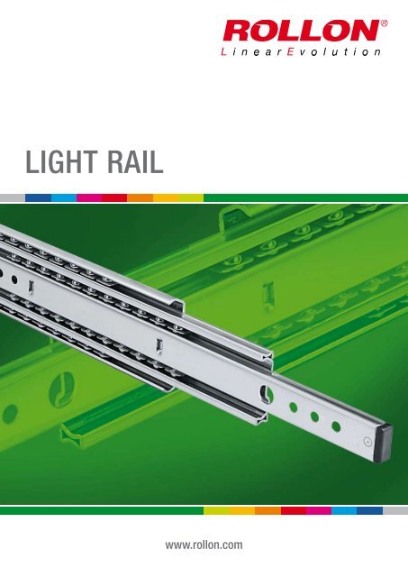
<strong>LIGHT</strong> <strong>RAIL</strong><br />
www.rollon.com
About <strong>Rollon</strong><br />
Development of global business<br />
Continual expansion and optimization of the portfolio<br />
1975 Parent company, <strong>Rollon</strong> S.r.l., founded in Italy<br />
1991 Founding of <strong>Rollon</strong> GmbH in Germany<br />
1995 Expansion of headquarters to new 4,000 m 2 factory<br />
Assembly starts in Germany<br />
Quality management certified to ISO 9001<br />
1998 <strong>Rollon</strong> B.V. in the Netherlands and <strong>Rollon</strong> Corporation in the<br />
USA are founded<br />
Expansion of German branch to new 1,000 m 2 plant<br />
1999 Founding of <strong>Rollon</strong> S.A.R.L. in France<br />
Environmental management certified to ISO 14001<br />
2000 <strong>Rollon</strong> s.r.o. founded in Czech Republic<br />
2001 Expansion of headquarters to new 12,000 m 2<br />
manufacturing plant<br />
2007 Restructuring of the GmbH and alignment of production in<br />
Germany to customer-specific adaptations<br />
Takeover of the assets of a manufacturer of linear rail<br />
systems<br />
2008 Expansion of sales network in Eastern Europe and Asia<br />
Founded in 1975, <strong>Rollon</strong> manufactured high-precision linear roller bearings<br />
for the machine tool industry. Early on, <strong>Rollon</strong> started manufacturing<br />
linear bearings based on the bearing-cage design. In 1979, the Compact<br />
Rail self-aligning linear bearings joined the Telescopic Rail industrial<br />
drawer slides and Easy Rail linear bearings and became the basis<br />
of the strong foundation on which the company is building upon today.<br />
Continuing optimization of these core products still remains one of the<br />
most important goals at <strong>Rollon</strong>. The development of the patented Compact<br />
Rail linear bearing, which uses different proprietary rail profiles and highprecision<br />
radial ball bearing sliders, enables the compensation of height<br />
and angle mounting defects in applications, and is only one example of<br />
the continuing efforts to innovative the development of our existing product<br />
families. In the same manner, we continually introduce innovative<br />
new product familiesdisplaying our continuing product development and<br />
optimization in the industry. These include:<br />
■ 1994 Light Rail - full and partial extension telescopic in lightweight<br />
design<br />
■ 1996 Uniline - belt driven linear actuators<br />
■ 2001 Ecoline - economical aluminum linear actuators<br />
■ 2002 X-Rail - inexpensive formed steel linear guides<br />
■ 2004 Curviline - curved monorail profile rail guide with roller carriages<br />
■ 2007 Monorail - miniature sizes and full sized<br />
Each further innovation of our linear bearings is built upon the our extensive<br />
knowledge of the nine product families in production today as well as<br />
on the current market demands. <strong>Rollon</strong> is the ultimate linear technology<br />
for any application needs.
Content<br />
1 Product explanation<br />
Full and partial extension in lightweight design<br />
2 Technical data<br />
Performance characteristics and remarks<br />
3 Product dimensions<br />
LPS 38<br />
LFS 46<br />
LFS 57<br />
LFS 58 SC<br />
LFS 70<br />
4 Technical instructions<br />
Load capacities<br />
Speed, Temperature, Lubrication,<br />
Corrosion protection<br />
Installation instructions<br />
4<br />
6<br />
7<br />
8<br />
9<br />
10<br />
11<br />
12<br />
13<br />
14<br />
Ordering Key<br />
Ordering key with explanations<br />
Portfolio
1 Product explanation<br />
Product explanation<br />
Light Rail: Full and partial extensions in lightweight design<br />
Fig. 1<br />
The Light Rail product family consists of five series with full and partial<br />
extensions in lightweight design. It is ideal for applications in which the<br />
mass of the rail is just as important as the bending rigidity.<br />
The most important characteristics:<br />
■ Light and quiet running with heavy loads<br />
■ Long service life without maintenance<br />
■ Effective self-cleaning of the ball track<br />
■ High functional reliability<br />
■ Structural elasticity capable of absorbing minor impacts and absence<br />
of permanent deformation<br />
■ Not sensitive to side impacts<br />
Preferred areas of application:<br />
■ Beverage industry<br />
■ Automotive<br />
■ Construction and machine technology (e.g., housing)<br />
■ Packaging machines<br />
■ Railcars (e. g., maintenance and battery extensions)<br />
■ Special machines<br />
4 www.rollon.com
Product explanation 1<br />
LPS 38<br />
Partial extension with rails made of hot-dipped galvanized steel and plastic<br />
ball cages.<br />
Fig. 2<br />
LFS 46<br />
Detachable internal rail which can be released with a latch. Rails are made<br />
of bright chrome-plated steel, the ball cages of steel and plastic. Roll back<br />
protection in closed position.<br />
Fig. 3<br />
LFS 57<br />
Full extension with rails made of hot-dipped galvanized steel and zincplated<br />
steel ball cages. Roll back protection in closed position.<br />
Fig. 4<br />
LFS 58 SC<br />
Full extension with automatic retraction and damping. The automatic retraction<br />
system is assisted by a spring-loaded mechanism that allows<br />
the rail to get back to a complete retraction before reaching the closed<br />
position.<br />
Fig. 5<br />
LFS 70<br />
Full extension with rails made of zinc-plated galvanized and blue passivated<br />
steel. The ball cages are made of zinc-plated steel. Heavy load<br />
end stop in opened and closed position. Roll back protection in closed<br />
position.<br />
Fig. 6<br />
www.rollon.com<br />
5
2 Technical data<br />
Technical data<br />
Intermediate element<br />
Exterior rail<br />
Ball cage<br />
Interior rail<br />
Fig. 7<br />
Performance characteristics:<br />
■ Extension speed (depending on application):<br />
Extension distance 100 - 500 mm: max. 0.5 m/s ( 19.69 in/s )<br />
Extension distance 600 mm: max. 0.4 m/s ( 15.75 in/s )<br />
Extension distance 700 mm: max. 0.3 m/s ( 11.81 in/s )<br />
■ LFS 58 SC series with automatic retraction<br />
■ Temperature range: +10 °C to +40 °C (+50 °F to +104 °F)<br />
Temporary storage and transport temperature:<br />
-20 °C to max. +80 °C (-4 °F to +176 °F)<br />
■ All systems are lubricated for life<br />
■ Rail material: hot-dipped galvanized steel or chromated steel<br />
■ Ball cage material: zinc-plated steel or plastic<br />
■ Ball material: hardened carbon steel<br />
Remarks:<br />
■ Assembly in cross-sectional width, here a positive tolerance of<br />
+0.5 mm is recommended (mounted under tension). If the extensions<br />
are installed with too small a tolerance, the service life is decreased<br />
■ Load capacity is per single rail (not per pair)<br />
■ Cycle data applies to the use of an extension pair (recommended)<br />
■ Vertical use of extensions (radial load) is recommended<br />
■ The load capacity is reduced with horizontal installation (see pg. 12)<br />
■ Cathodic edge protection, additional corrosion protection with powder<br />
coating on request<br />
■ Roll back protection in closed position is friction locked<br />
(except LPS 38)<br />
■ Not suitable for moments – must be used as extension pair<br />
6 www.rollon.com
Product dimensions 3<br />
Product dimensions<br />
LPS 38<br />
Length<br />
13.0<br />
Length<br />
AV<br />
26 32<br />
5,1<br />
X<br />
37.5<br />
M4 (2x)<br />
44<br />
A<br />
13.0 +0.5<br />
B<br />
4,7<br />
Installation space<br />
Fixing with M5 screws (head height 2.5 mm)<br />
All dimensions given in mm<br />
Fig. 8<br />
Type Size Length<br />
Extension<br />
loss<br />
Stroke*<br />
A<br />
B<br />
X<br />
Load<br />
capacity**<br />
Load<br />
capacity**<br />
Weight**<br />
[mm]<br />
AV<br />
[mm]<br />
[mm]<br />
[mm]<br />
[mm]<br />
[mm]<br />
C 0rad<br />
[N]<br />
C 0ax<br />
[N]<br />
[kg]<br />
LPS 38<br />
* The stroke is the difference of the length, minus the extension loss AV<br />
** The given load capacities and weights apply for a single extension<br />
242<br />
154 166 202 192<br />
0.30<br />
88<br />
317 229 241 277 256 0.40<br />
175 50<br />
398<br />
298 322 358 352 0.50<br />
100<br />
473 373 397 433 416 0.60<br />
Tab. 1<br />
Note: The given load capacities are guidelines with 100,000 cycles and<br />
uniform load distribution (area load) when using all mounting holes. The<br />
load values must be reduced in unfavorable conditions.<br />
www.rollon.com<br />
7
3 Product dimensions<br />
LFS 46<br />
12.7<br />
Stroke<br />
45.5<br />
33<br />
9 128<br />
A<br />
Length -2 mm<br />
C<br />
B<br />
35 D E<br />
9 12,6 12,7<br />
Length<br />
9 12,7<br />
4,4<br />
4,4 x 9,3<br />
Latch for separable interior rail<br />
6,3 6,3<br />
4,6 x 9,5<br />
4,6 4,6<br />
4,6 x 9,5<br />
12.7 +0.5<br />
Installation space<br />
Fixing with M4 screws (head height 2.2 mm)<br />
All dimensions given in mm<br />
Fig. 9<br />
Type Size Length<br />
Stroke<br />
A<br />
B<br />
C<br />
D<br />
E<br />
Load<br />
capacity*<br />
Load<br />
capacity*<br />
Weight*<br />
[mm]<br />
[mm]<br />
[mm]<br />
[mm]<br />
[mm]<br />
[mm]<br />
[mm]<br />
C 0rad<br />
[N]<br />
C 0ax<br />
[N]<br />
[kg]<br />
300 305 - - 242 192 - 150<br />
0.48<br />
400 406 -<br />
342<br />
96<br />
0.64<br />
256<br />
160<br />
450 457 - 392 160 175<br />
0.71<br />
LFS 46<br />
50<br />
500 508 - 352 442<br />
128 0.79<br />
550 559<br />
492 224 192<br />
0.88<br />
224 416<br />
200<br />
600 610 542 224 0.95<br />
Tab. 2<br />
* The given load capacities and weights apply for a single extension<br />
Note: The given load capacities are guidelines with 80,000 cycles and<br />
uniform load distribution (area load) when using all mounting holes. The<br />
load values must be reduced in unfavorable conditions.<br />
8 www.rollon.com
Product dimensions 3<br />
LFS 57<br />
17.5<br />
Stroke<br />
Length<br />
50<br />
8/90° 9,5/90°<br />
5,1<br />
Length<br />
57.4<br />
6,5<br />
32<br />
A<br />
B<br />
32<br />
C<br />
16<br />
17.5 +0.5<br />
Installation space<br />
Fixing on the interior rail with M4 countersunk head screws (head height 2.2 mm)<br />
Fixing on the exterior rail with M5 countersunk head screws (head height 2.5 mm)<br />
All dimensions given in mm<br />
Fig. 10<br />
Type Size Length<br />
Stroke*<br />
A<br />
B<br />
C<br />
Load<br />
capacity**<br />
Load<br />
capacity**<br />
Weight**<br />
[mm]<br />
[mm]<br />
[mm]<br />
[mm]<br />
[mm]<br />
C 0rad<br />
[N]<br />
C 0ax<br />
[N]<br />
[kg]<br />
LFS 57<br />
* The stroke is the sum of the length, and the over extension<br />
** The given load capacities and weights apply for a single extension<br />
300 350<br />
104 160 250<br />
0.84<br />
128<br />
350 400 152<br />
300 0.98<br />
400 450<br />
168 256 325 1.13<br />
160<br />
450 500 224 350 1.27<br />
500 550<br />
208<br />
1.42<br />
224<br />
375 80<br />
550 600 256 1.57<br />
600 650<br />
240<br />
1.71<br />
288<br />
384<br />
650 700 288 1.86<br />
400<br />
700 750<br />
312 2.01<br />
320<br />
750 800 360 2.16<br />
Tab. 3<br />
Note: The given load capacities are guidelines with 100,000 cycles and<br />
uniform load distribution (area load) when using all mounting holes. The<br />
load values must be reduced in unfavorable conditions.<br />
www.rollon.com<br />
9
3 Product dimensions<br />
LFS 58 SC<br />
16.0<br />
Stroke<br />
8/90° 9,5/90°<br />
5,1<br />
Length<br />
57.5<br />
32<br />
A<br />
B<br />
16.0 +0.5<br />
Installation space<br />
32<br />
6,5<br />
C<br />
Fixing on the interior rail with M4 countersunk head screws (head height 2.2 mm)<br />
Fixing on the exterior rail with M5 countersunk head screws (head height 2.5 mm)<br />
16<br />
All dimensions given in mm<br />
Fig. 11<br />
Type Size Length<br />
Stroke<br />
A<br />
B<br />
C<br />
Load<br />
capacity*<br />
Weight*<br />
[mm]<br />
[mm]<br />
[mm]<br />
[mm]<br />
[mm]<br />
C 0rad<br />
[N]<br />
[kg]<br />
LFS 58<br />
* The given load capacities and weights apply for a single extension<br />
400 434 128 128 224 200 1.10<br />
450 484<br />
160 256 250 1.25<br />
160<br />
500 534<br />
275 1.40<br />
192 320<br />
550 584 192 300 1.55<br />
Tab. 4<br />
Note: The given load capacities are guidelines with 100,000 cycles and<br />
uniform load distribution (area load) when using all mounting holes. The<br />
load values must be reduced in unfavorable conditions. Horizontal installation<br />
is not possible due to the damping system. The damping effect is<br />
reduced for loads of 450 N and higher per extension pair.<br />
10 www.rollon.com
Product dimensions 3<br />
LFS 70<br />
18.0<br />
70.0<br />
Stroke<br />
Length -3 mm<br />
D<br />
C<br />
B<br />
A<br />
32 2 x 16 ø 6.5 x 9.5 / 90°<br />
18.0 +0.5<br />
Installation space<br />
32 2 x 16<br />
A<br />
B<br />
ø 6.5 x 9.5 / 90°<br />
C<br />
D<br />
Length<br />
Fixing with M5 countersunk head screws (head height 2.5 mm)<br />
or euro screws (countersunk height 1.5 mm)<br />
All dimensions given in mm<br />
Fig. 12<br />
Type Size Length<br />
Stroke<br />
A<br />
B<br />
C<br />
D<br />
Load<br />
capacity*<br />
Load<br />
capacity*<br />
Weight*<br />
[mm]<br />
[mm]<br />
[mm]<br />
[mm]<br />
[mm]<br />
[mm]<br />
C 0rad<br />
[N]<br />
C 0ax<br />
[N]<br />
[kg]<br />
400 400 - - - 288 525<br />
1.55<br />
450 450 - - 160 320 575 1.74<br />
500 500 - - 192 384<br />
1.94<br />
LFS 70<br />
550 550 - -<br />
150 2.13<br />
224 448 650<br />
600 600 - - 2.32<br />
700 700 - 192 384 576 2.70<br />
800 800 - 224 448 672 600 3.10<br />
* The given load capacities and weights apply for a single extension<br />
1100 1100 224 448 672 896 450 100 4.25<br />
Tab. 5<br />
Note: The given load capacities are guidelines with 100,000 cycles and<br />
uniform load distribution (area load) when using all mounting holes. The<br />
load values must be reduced in unfavorable conditions.<br />
www.rollon.com<br />
11
4 Technical instructions<br />
Technical instructions<br />
Load capacities<br />
Vertical installation (radial load)<br />
The given loading capacities are guidelines for an extension rail vertically<br />
mounted with uniform load distribution using all mounting holes.<br />
The load values must be reduced in unfavorable conditions.<br />
Fig. 13<br />
Horizontal installation (axial load)<br />
For horizontal mounted extensions the load capacity is reduced<br />
(see pg. 7ff, tab. 1 to tab. 5).<br />
Fig. 14<br />
12 www.rollon.com
Technical instructions 4<br />
Speed<br />
The extension speed is determined by the size of the intermediate elements.<br />
Therefore, the maximum extension speed is inversely proportional<br />
to the overall extension of the rails (see fig. 15). The maximum extension<br />
speed is also directly related to the applied load and operating time. The<br />
indicated data refers to continuous operation at the maximum load capacity.<br />
m/s<br />
0,6<br />
0,5<br />
0,4<br />
0,3<br />
0,2<br />
0,1<br />
Speed<br />
Speed<br />
0<br />
100 200 300 400 500 600 700 mm<br />
Fig. 15<br />
Temperature<br />
Continual operating temperature of the Light Rail extensions is +10 °C to<br />
+40 °C. Temporary storage and transport temperature: -20 °C to max.<br />
+80 °C.<br />
For more information please contact the <strong>Rollon</strong> Application engineering<br />
department.<br />
Lubrication<br />
All extensions of the Light Rail product family are lubricated for life.<br />
Different lubricants for special applications are available upon request.<br />
Example: Lubricant with FDA approval for use in the food industry.<br />
For more information please contact the <strong>Rollon</strong> Application engineering<br />
department.<br />
Corrosion protection<br />
Base material for the Light Rail product family is cold-rolled, hot-dipped<br />
galvanized steel. The cathodic edge protection offers a perfect combination<br />
of quality and cost-efficiency. The surface protection conforms to<br />
RoHS.<br />
For more information please contact the <strong>Rollon</strong> Application engineering<br />
department.<br />
www.rollon.com<br />
13
4 Technical instructions<br />
Installation instructions<br />
■ The existing internal stops are not designed to stop the moving load.<br />
They are only supposed to retain the ball-cage and prevent the internal<br />
parts to slide out of the assembly. An external end-stop must always<br />
be installed to stop the moving load.<br />
■ To achieve optimum running properties, high service life and rigidity, it<br />
is necessary to fix the Light Rail extensions with all accessible holes on<br />
a rigid and level surface. When using an extension pair, please observe<br />
the parallelism of the installation surfaces. The fixed and movable rails<br />
fit to the rigid assembly construction.<br />
■ Light Rail full and partial extensions are suitable for use in automatic<br />
systems. For this, the stroke should remain constant in all moving cycles<br />
and the extension speed must be checked (see pg. 13, fig. 15).<br />
The movement of the extensions is enabled by internal ball cages,<br />
which could experience an offset from the original position with differing<br />
strokes. This phase offset can have a negative effect on the<br />
running properties or limit the stroke. If differing strokes occur in an<br />
application, the drive force must be sufficiently dimensioned in order to<br />
appropriately synchronize the ball cage offset. As an alternative, an extra<br />
full stroke cycle can be performed every certain number of cycles,<br />
in order to re-phase the ball cage in its correct position.<br />
Horizontally installed guides<br />
Horizontally intalled extesions can support tension or compression loads<br />
(see figs. 16 and 17).<br />
Fig. 16<br />
For the horizontal mounting of extensions with compression loads, please<br />
keep the following conditions into account: The Hertzian stress of the balls<br />
in no longer effective due to the expansion of the rail profile; the nominal<br />
tension tolerance of +0.5 mm is eliminated due to the installation configuration.<br />
Both the above mentioned conditions contribute to a significant<br />
reduction of the axial load capacity.<br />
Horizontally-mounted rails (axial load) also determine a considerably higher<br />
deflection of the extended tips if compared to traditionally verticallymounted<br />
rails (radial load).<br />
Fig. 17<br />
14 www.rollon.com
Portfolio<br />
Portfolio<br />
COMPACT <strong>RAIL</strong><br />
Rugged roller sliders with innovative<br />
self adjustment<br />
MONO <strong>RAIL</strong><br />
Profile guideways for highest degrees<br />
of precision<br />
CURVILINE<br />
Curvilinear rails for constant<br />
and variable radii<br />
MINIATURE MONO <strong>RAIL</strong><br />
Miniature format profile guideways<br />
with unique ball design<br />
EASY <strong>RAIL</strong><br />
Compact, versatile linear bearings<br />
TELESCOPIC <strong>RAIL</strong><br />
Smooth-running telescopic linear<br />
bearing drawer slides with<br />
low deflection under heavy loads<br />
UNILINE<br />
Steel-reinforced, belt-driven linear actuators<br />
with hardened steel linear bearings<br />
and precision radial ball bearing rollers<br />
X-<strong>RAIL</strong><br />
Roller embossed stainless steel profiles<br />
for the use in rough environments
Ordering key<br />
Ordering key<br />
Telescopic rails<br />
LFS 58- 400 SC<br />
Rail type<br />
Size<br />
Automatic retraction only in LFS 58 SC see pg. 10<br />
Rail length in mm<br />
Ordering example: LFS58-0400SC<br />
Notes on ordering: The rail lengths are always indicated as 4 digits with 0 prefixes
Fold out ordering key<br />
Fold out ordering key<br />
To make this product catalog as simple as possible for you to use, we have<br />
included the following easy-to-read chart.<br />
Your advantages:<br />
■ Description and ordering designations easy to read at one glance<br />
■ Simplified selection of the correct product<br />
■ Links to detailed descriptions in the catalog
ROLLON S.r.l.<br />
Via Trieste 26<br />
I-20871 Vimercate (MB)<br />
Tel.: (+39) 039 62 59 1<br />
Fax: (+39) 039 62 59 205<br />
E-Mail: infocom@rollon.it<br />
Italy<br />
www.rollon.it<br />
Germany<br />
ROLLON GmbH<br />
Bonner Strasse 317-319<br />
D-40589 Düsseldorf<br />
Tel.: (+49) 211 95 747 0<br />
Fax: (+49) 211 95 747 100<br />
E-Mail: info@rollon.de<br />
www.rollon.de<br />
Netherlands<br />
ROLLON B.V.<br />
Ringbaan Zuid 8<br />
6905 DB Zevenaar<br />
Tel.: (+31) 316 581 999<br />
Fax: (+31) 316 341 236<br />
E-Mail: info@rollon.nl<br />
www.rollon.nl<br />
France<br />
ROLLON S.A.R.L.<br />
Les Jardins d‘Eole, 2 allée des Séquoias<br />
F-69760 Limonest<br />
Tel.: (+33) (0)4 74 71 93 30<br />
Fax: (+33) (0)4 74 71 95 31<br />
E-Mail: infocom@rollon.fr<br />
www.rollon.fr<br />
USA<br />
ROLLON Corporation<br />
101 Bilby Road. Suite B<br />
Hackettstown, NJ 07840<br />
Tel.: (+1) 973 300 5492<br />
Fax: (+1) 908 852 2714<br />
E-Mail: info@rolloncorp.com<br />
www.rolloncorp.com<br />
All addresses of our global sales partners can also<br />
be found in the internet at www.rollon.com<br />
Changes and errors excepted. The text and images may be used only with our permission.<br />
RL_LR_<strong>EN</strong>_04/13