Download the PDF file (1.29 mb) - Usg-me.com
Download the PDF file (1.29 mb) - Usg-me.com
Download the PDF file (1.29 mb) - Usg-me.com

Create successful ePaper yourself
Turn your PDF publications into a flip-book with our unique Google optimized e-Paper software.
USG Middle East, Ltd.<br />
Dammam, Saudi Arabia<br />
E-mail: info@usg<strong>me</strong>.<strong>com</strong><br />
Fax: +966 3 8121029<br />
+966 3 8120995<br />
Riyadh, Saudi Arabia<br />
E-mail: riyadhsales@usg<strong>me</strong>.<strong>com</strong><br />
Fax: +966 1 4772734<br />
+966 1 4772734<br />
Jeddah, Saudi Arabia<br />
E-mail: jeddahsales@usg<strong>me</strong>.<strong>com</strong><br />
Fax: +966 2 6900643<br />
+966 2 6396741<br />
Dubai, U.A.E.<br />
E-mail: usgdubai@emirates.net.ae<br />
Fax: +971 4 2954566<br />
+971 4 2954443<br />
Beirut, Lebanon<br />
Fax: +961 1 361461<br />
+961 1 360888<br />
Manama, Bahrain<br />
E-mail: usgmiddleast.bahrain@hotmail.<strong>com</strong><br />
Fax: +973 17 581597<br />
+973 17 581596<br />
Web Site<br />
usg.<strong>com</strong>/<strong>me</strong><br />
Product Information<br />
See usg.<strong>com</strong>/<strong>me</strong> for <strong>the</strong> most<br />
up-to-date product information.<br />
Note<br />
USG Middle East, Ltd.<br />
reserves <strong>the</strong> right to change<br />
specifications or design and<br />
supply of products which differ<br />
from those described and<br />
illustrated without notice and<br />
without liability. All weights and<br />
<strong>me</strong>asures are nominal.<br />
Notice<br />
We shall not be liable for<br />
incidental and consequential<br />
damages, directly or indirectly<br />
sustained, nor for any loss<br />
caused by application of <strong>the</strong>se<br />
goods not in accordance with<br />
current printed instructions or<br />
for o<strong>the</strong>r than <strong>the</strong> intended use.<br />
Our liability is expressly limited<br />
to replace<strong>me</strong>nt of defective<br />
goods. Any claim shall be<br />
dee<strong>me</strong>d waived unless made<br />
in writing to us within thirty<br />
(30) days from date it was or<br />
reasonably should have been<br />
discovered.<br />
Safety First!<br />
Follow good safety/industrial<br />
hygiene practices during<br />
installation. Wear appropriate<br />
personal protective equip<strong>me</strong>nt.<br />
Read MSDS and literature<br />
before specification and<br />
installation.<br />
56 56 USG USG Drywall Partition and and Ceiling System<br />
X2781/5-08<br />
© 2008, USG Middle East, Ltd.
Wall Partition and<br />
Ceiling Suspension<br />
Systems<br />
Drywall<br />
Steel-Fra<strong>me</strong>d Systems
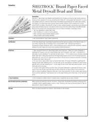
Lightweight fire- and sound-resistant assemblies provide an<br />
economical solution for single-, double- and multi-layer drywall<br />
partitions in <strong>com</strong><strong>me</strong>rcial, residential and institutional applications.<br />
Lightweight and Economical
User’s Guide<br />
This brochure explains :<br />
– Where drywall partitions and ceiling systems are used.<br />
– How to select and specify <strong>the</strong> appropriate <strong>com</strong>ponents.<br />
– The <strong>com</strong>ponents of drywall partitions and ceiling systems.<br />
Pages<br />
Understand Your System<br />
Overview<br />
Applications<br />
Components<br />
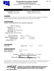
Performance Testing<br />
4<br />
6<br />
7<br />
9<br />
For More Information<br />
Web Site<br />
usg.<strong>com</strong>/<strong>me</strong><br />
3 USG Drywall Partition and Ceiling System
Overview<br />
Stud and Track<br />
Components for drywall stud and track products are roll-for<strong>me</strong>d from<br />
hot-dipped galvanized steel (corrosion resistant) and are available in a<br />
variety of sizes. The system is made from materials that <strong>com</strong>ply to both<br />
ASTM C645 and C527, with a minimum coating or equivalent.<br />
studs and tracks are produced in 3-<strong>me</strong>tre lengths unless o<strong>the</strong>rwise<br />
specified.<br />
Partition Wall<br />
Assembly<br />
Stud and Track<br />
Used for drywall partition, drywall studs and tracks are available in widths of 50, 64, 75, 92 and 100 mm.<br />
insulation material<br />
steel stud<br />
gypsum board<br />
steel stud<br />
steel track<br />
board protection channel<br />
corner bead<br />
4 USG Drywall Partition and Ceiling System
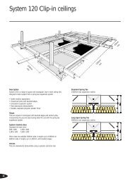
Ceiling Suspension System<br />
Components for drywall ceiling suspension products are roll-for<strong>me</strong>d<br />
from hot-dipped galvanized steel (corrosion resistant) and are available<br />
in a variety of sizes. The system is made from materials that <strong>com</strong>ply to<br />
both ASTM C645 and C527, with a minimum G40 coating or equivalent.<br />
Ceiling suspension products are produced in 3-<strong>me</strong>tre lengths<br />
unless o<strong>the</strong>rwise specified.<br />
Drywall Ceiling<br />
Assembly<br />
Furring Channel, Peri<strong>me</strong>ter Angle, Primary Channel<br />
Used for ceiling suspension, drywall ceiling framing is available in <strong>the</strong> following sizes: 22x69mm, 25x25mm,<br />
and 12x38mm.<br />
hanger<br />
primary channel<br />
wire coupling clip<br />
primary channel hanger bracket<br />
furring channel<br />
peri<strong>me</strong>ter<br />
angle<br />
gypsum board<br />
5 USG Drywall Partition and Ceiling System
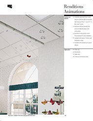
Applications<br />
These systems are adaptable to virtually any type of new construction,<br />
including <strong>com</strong><strong>me</strong>rcial, residential, institutional and industrial. They<br />
are also useful in renovation to provide smooth, durable interior surfaces.<br />
Fire-resistant assemblies are also available. These partitions provide<br />
efficient sound insulation at all frequencies. The multilayer designs<br />
provide exceptional isolation at low, middle and high frequencies, making<br />
<strong>the</strong>m ideal for isolating loud music, <strong>me</strong>chanical equip<strong>me</strong>nt and<br />
amplified speech sound sources. STC ratings are up to 62 for multilayer,<br />
55 for double-layer, and 55 for single-layer resilient partitions, and<br />
54 for single-layer ceilings. They are lightweight and thin, allowing<br />
for <strong>the</strong> most efficient use of materials and space.<br />
6 USG Drywall Partition and Ceiling System
Components<br />
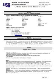
USG drywall stud and track systems have been <strong>com</strong>prehensively tested for<br />
fire resistance ratings only when all of <strong>the</strong> system <strong>com</strong>ponents are used<br />
toge<strong>the</strong>r. Substitutions of any of <strong>the</strong> <strong>com</strong>ponents are not re<strong>com</strong><strong>me</strong>nded<br />
and are not supported by USG. Refer to <strong>the</strong> appropriate product material<br />
safety data sheet for <strong>com</strong>plete health and safety information.<br />
1-Track<br />
(U-Shaped Pro<strong>file</strong>)<br />
Cross Section<br />
30<br />
10<br />
1.5<br />
A<br />
6<br />
Components Di<strong>me</strong>nsions (mm) Specifications<br />
Item Number Description A Thickness Length Zinc Coating Packaging<br />
TR350 Wall Track 50x30 50 0.5–0.6 3000 G40–G60 Bundle<br />
TR364 Wall Track 64x30 64<br />
TR375 Wall Track 75x30 75<br />
TR392 Wall Track 92x30 92<br />
TR3100 Wall Track 100x30 100<br />
2-Stud Cross Section Plan View<br />
(C-Sharped Pro<strong>file</strong>)<br />
22.5<br />
36 knurling 34<br />
10<br />
1.5<br />
A<br />
6<br />
38.5<br />
32 64<br />
Components Di<strong>me</strong>nsions (mm) Specifications<br />
Item Number Description A Thickness Length Zinc Coating Packaging<br />
ST3550 Wall Stud 50x36 48.8 0.5–0.6 3000 G40–G60 Bundle<br />
ST3564 Wall Stud 64x36 62.8<br />
ST3575 Wall Stud 75x36 73.8<br />
ST3592 Wall Stud 92x36 90.8<br />
ST35100 Wall Stud 100x36 98.8<br />
7 USG Drywall Partition and Ceiling System
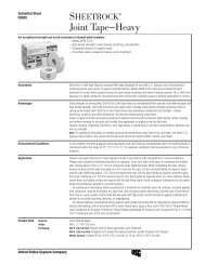
Components<br />
3-Furring Channel<br />
(O<strong>me</strong>ga-Shaped Pro<strong>file</strong>)<br />
Cross Section<br />
69<br />
13 43 13<br />
22<br />
knurling<br />
21<br />
36<br />
Components Di<strong>me</strong>nsions (mm) Specifications<br />
Item Number Description Thickness Length Zinc Coating Packaging<br />
FC2269 Furring Channel Light Duty 0.5–0.6 3000 G40-G60 Bundle<br />
4-Peri<strong>me</strong>ter Angle<br />
(L-Shaped Pro<strong>file</strong>)<br />
Cross Section<br />
25<br />
25<br />
Components Di<strong>me</strong>nsions (mm) Specifications<br />
Item Number Description Thickness Length Zinc Coating Packaging<br />
PA2525 Peri<strong>me</strong>ter Angle 0.5–0.6 3000 G40–G60 Bundle<br />
25 x 25 L-Pro<strong>file</strong><br />
5-Primary Channel<br />
(U-Shaped Pro<strong>file</strong>)<br />
Cross Section<br />
12<br />
38<br />
Components Di<strong>me</strong>nsions (mm) Specifications<br />
Item Number Description Thickness Length Zinc Coating Packaging<br />
PC1238 Primary U Channel 0.8–1.0 3000 G40–G60 Bundle<br />
12 x 38 Pro<strong>file</strong><br />
8 USG Drywall Partition and Ceiling System
Installation<br />
How to Build wih Attach track to floor and ceiling Use straight snips for cutting<br />
Steel Stud and Track<br />
steel stud<br />
steel stud or<br />
steel track<br />
straight snips<br />
steel track<br />
Screw lengths of track to <strong>the</strong> floor and ceiling. Tracks are<br />
slightly wider than studs, so studs snap right in.<br />
To trim to correct length, cut both side flanges of a steel<br />
stud, using straight-cut aviation snips. Then bend one<br />
flange up and cut across <strong>the</strong> stud’s web.<br />
Screw stud to track<br />
steel track<br />
pan head screw<br />
C-clamp<br />
locking pliers<br />
steel stud<br />
Use bushings for electric cable<br />
steel track<br />
steel stud<br />
knockout<br />
plastic bushing<br />
plastic ties<br />
screwed to studs<br />
electric cable<br />
Join studs to tracks by clamping <strong>the</strong> two <strong>me</strong>mbers tightly Secure electrical cable along <strong>the</strong> center line of each stud<br />
with a C-clamp locking pliers and driving a pan-head with plastic ties screwed to <strong>the</strong> studs. Pop a plastic<br />
screw in <strong>the</strong> middle where <strong>the</strong>y <strong>me</strong>et.<br />
bushing into each knockout to keep <strong>the</strong> cable from<br />
– Drive <strong>the</strong> screws at <strong>me</strong>dium speed. rubbing against <strong>the</strong> sharp edges.<br />
– Choose a clutch setting strong enough to drive <strong>the</strong> screw<br />
ho<strong>me</strong>, but not so strong that it strips <strong>the</strong> screw hole and<br />
weakens <strong>the</strong> joint.<br />
9 USG Drywall Partition and Ceiling System
Installation<br />
– Add wood nailers as needed for doors, windows<br />
and cabinets.<br />
– Hang drywall or sheathing using 3.1 cm self-tapping<br />
drywall screws spaced every 20.3 cm along edges (where<br />
two sheets <strong>me</strong>et on a stud) and 30.5 cm on center elsewhere.<br />
– Check local building codes. They may require screws<br />
placed closer toge<strong>the</strong>r, and having too many screws is<br />
preferable to having to add more after <strong>the</strong> inspector co<strong>me</strong>s.<br />
steel track<br />
steel stud<br />
gypsum board<br />
steel track<br />
Installation —Stud<br />
– For standard installation insert <strong>the</strong> studs into <strong>the</strong> top and<br />
floor tracks and twist to lock as shown.<br />
The friction fit will hold <strong>the</strong> stud in place.<br />
– Non-fire rated partitions—allow a 10mm gap between <strong>the</strong><br />
top of <strong>the</strong> stud and inside face of <strong>the</strong> track, as illustrated.<br />
Insert stud into track on angle,<br />
<strong>the</strong>n twist to lock into position.<br />
Safety First<br />
– Don’t try nailing trim into steel studs. It will not hold. Instead, use specially designed trim screws for <strong>the</strong> job.<br />
– Cut steel is sharp—wear gloves.<br />
– Always wear eye protection when cutting steel and when driving screws. A screw may jump off <strong>the</strong> power screwdriver<br />
and can cause eye injuries.<br />
– Make sure that architect’s or designer’s plans aren’t drawn for wood di<strong>me</strong>nsions.<br />
10 USG Drywall Partition and Ceiling System
Installation<br />
Installation<br />
Plasterboard to Stud<br />
To attach plasterboard to light gauge steel studs, a slightly different technique is required <strong>com</strong>pared to conventional<br />
timber studs. Use <strong>the</strong> following instructions to ensure correct installation.<br />
Correct Method<br />
As <strong>the</strong> face of a steel stud can deflect initially, using <strong>the</strong> correct sequence to attach <strong>the</strong> board is important. Attach <strong>the</strong><br />
first board to <strong>the</strong> open side of <strong>the</strong> stud. The face will deflect slightly, <strong>the</strong>n will pull tight against <strong>the</strong> board. Support <strong>the</strong><br />
stud to avoid twisting and fully screw <strong>the</strong> board to this stud before continuing. The next sheet can now be screwed<br />
to <strong>the</strong> closed side of <strong>the</strong> stud. Deflection will be minimal as <strong>the</strong> first sheet helps keep a rigid assembly and <strong>the</strong> result<br />
is a correct flat joint.<br />
Incorrect Method<br />
If a board is screwed to <strong>the</strong> closed side first, <strong>the</strong>n <strong>the</strong> face is able to deflect when <strong>the</strong> next board is screwed to<br />
<strong>the</strong> open side. This can permanently bend <strong>the</strong> face, resulting in a lipped joint.<br />
Plasterboard Fixing Sequence<br />
The boards shall be fixed in <strong>the</strong> sequence shown A B C D. When installing <strong>the</strong> first side (A and B), fasten <strong>the</strong> board<br />
at <strong>the</strong> edges only (1 & 2). The centre must not be fastened until <strong>the</strong> second side (C & D) have been installed. Locate<br />
board joints on each side of <strong>the</strong> wall on alternate studs. Screws shall be fastened in sequence 1-6. Correct sequence<br />
will minimize any misalign <strong>me</strong>nt problems and result in a higher quality finish.<br />
.<br />
11 USG Drywall Partition and Ceiling System
Installation<br />
Installation<br />
Details<br />
Spliced Studs<br />
When heights greater than standard pre-cut lengths are<br />
required, using <strong>the</strong> ‘boxing’ feature single studs can be<br />
spliced toge<strong>the</strong>r to extend to <strong>the</strong> required height. Minimum<br />
overlap: 3 x depth of stud, for example,<br />
– 98.8mm stud = 300 mm overlap<br />
– 63.8mm stud = 200 mm overlap<br />
– Rivets: 4mm dia. mild steel, 3 per face (total 6)<br />
Splice must be within 25% of wall height, and splices<br />
should be alternated top and bottom. Splices may be<br />
used in fire rated walls, provided steel rivets are used<br />
(not aluminium).<br />
Nogging Single Nogging Continuous Nogging<br />
Where specific load require<strong>me</strong>nts or fixtures are needed, For certain applications such as towel rails, pictures<br />
an individual nog can be for<strong>me</strong>d from <strong>the</strong> track pro<strong>file</strong> to and suspended ceiling peri<strong>me</strong>ter fixing etc, continuous<br />
fit between <strong>the</strong> studs. Cut and trim as shown and fix with nogging may be required. Use <strong>the</strong> track, cut, notch<br />
3mm dia<strong>me</strong>ter rivets. The maximum height tables do not and fix as shown. This will normally link 5-6 studs at<br />
allow for heavy loads to be attached to <strong>the</strong> walls such as 600mm centres. Double sided can also be achieved if<br />
TV’s, cantilevered benches / bookcases/ toilets etc. Where required by repeating on <strong>the</strong> o<strong>the</strong>r stud face.<br />
such equip<strong>me</strong>nt must be hung off a wall, specifically<br />
designed supports are required. Please contact USG Interiors<br />
for this assistance.<br />
Control Joints<br />
Control joints shall be provided at 9m centres in partitions. Top and bottom track may be continuous through<br />
control joints. For construction refer Winstone Wallboards Gib ® . Interior Solutions Site Guide February 1998 and CLC’s<br />
Appraisal 21/09/98.<br />
12 USG Drywall Partition and Ceiling System
What are <strong>the</strong> Advantages<br />
of USGME Products?<br />
USG products offer several advantages:<br />
– Meet or exceed all international code require<strong>me</strong>nts (ISO – EN).<br />
– Fully <strong>com</strong>patibile with all standard gypsum boards.<br />
– Installation - knurled flanges for easier attach<strong>me</strong>nt of facing materials.<br />
– Flexural tensile strength.<br />
– Easy to cut using tin snips.<br />
– Mineral wool can be easily installed to upgrade sound insulation.<br />
– Durability of flexural tensile strength and load bearing capacity<br />
against moisture.<br />
– Resistance and reaction to fire.<br />
– Improved safety by reducing sharp edges and lips.<br />
– Sound absorption (less noise transmission through walls and ceiling).<br />
– A better, quieter building.<br />
– Large range of sizes available.<br />
13 USG Drywall Partition and Ceiling System