EDX Product Brochure - Evapco
EDX Product Brochure - Evapco
EDX Product Brochure - Evapco

Create successful ePaper yourself
Turn your PDF publications into a flip-book with our unique Google optimized e-Paper software.
®<br />
®<br />
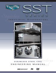
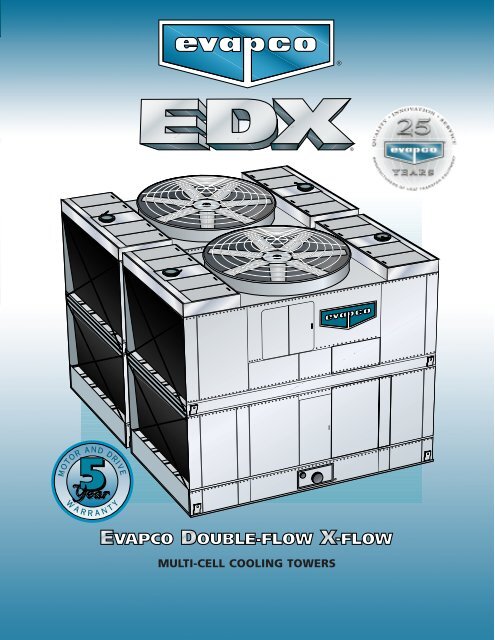
MULTI-CELL COOLING TOWERS
EVAPCO’s Double Flow Cross Flow<br />
Cooling Tower<br />
The Better Crossflow Choice!<br />
S<br />
ince its founding in 1976,<br />
EVAPCO, Inc. has become<br />
a world-wide leader in<br />
supplying quality cooling equipment<br />
for thousands of customers<br />
in both the commercial and<br />
industrial markets.<br />
EVAPCO’s success has been the<br />
result of a continual commitment<br />
to product improvement,<br />
quality workmanship and a dedication<br />
to providing unparalleled<br />
service.<br />
EVAPCO <strong>EDX</strong> Cooling Towers - Another Cooling Tower product innovation<br />
from EVAPCO to add to an already impressive Cooling Tower<br />
line up.<br />
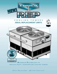
The <strong>EDX</strong> is an Induced-Draft Cooling Tower which is ideal for large,<br />
continuous cooling tower cell applications.<br />
The <strong>EDX</strong> will complement EVAPCO’s already extensive Cooling Tower<br />
product lines and is available in:<br />
25 Cataloged Models<br />
(2) Two Plan Areas<br />
24’ x 22’ & 28’ x 24’<br />
Capacity Range<br />
1414 to 2208 Nominal Tons<br />
With 2208 Nominal Tons in a Two-Cell Cooling Tower,<br />
EVAPCO’s <strong>EDX</strong> Double Flow Crossflow has one of the<br />
highest thermal capacity rating of any factory assembled<br />
Induced-Draft, Crossflow Cooling Tower in the Industry!<br />
The <strong>EDX</strong> is the one and only crossflow cooling tower with EVAPCO’s<br />
easy maintenance design as standard.<br />
Our emphasis on research and<br />
development has led to many<br />
product innovations – a hallmark<br />
of EVAPCO through the years.<br />
The ongoing R & D Program<br />
enables EVAPCO to provide the<br />
most advanced products in the<br />
industry – technology for the<br />
future, available today.<br />
With 13 facilities in seven countries<br />
and over 160 sales offices<br />
in 42 countries world-wide,<br />
EVAPCO is ready to assist in all<br />
your equipment needs.<br />
The <strong>EDX</strong> features:<br />
• Type 304 Stainless Steel Hot Water Distribution Basins and Suction<br />
Strainers<br />
• G-235 Galvanized Steel Unit Construction<br />
• Sliding Hot Water Basin Covers Constructed of FRP<br />
• EVAPCO’s POWER-BAND DRIVE SYSTEM with (5) Five Year Motor<br />
and Drive Warranty<br />
• Bottom Supported, Bonded Fill Section - No Loose Fill Sheets!<br />
• Outlet is Beveled for Weld and Grooved for a Mechanical Coupling<br />
• Positive Closure Balancing Valve for Water Inlets<br />
• Easy Maintenance Features<br />
(1) Large Basin and Plenum Access Doors<br />
(2) Swing Out Motor Base<br />
(3) Elevated Fill Section to Facilitate Maintenance<br />
The <strong>EDX</strong> Cooling Tower is the Better Crossflow Choice!<br />
©2001 EVAPCO, INC.<br />
2
FEATURES AND BENEFITS<br />
Standard Stainless Steel<br />
Hot Water Basins<br />
• The Hot Water Basins of a<br />
Cooling Tower are the Most<br />
Susceptible to the Effects of<br />
Corrosion and Wear<br />
• Type 304 Stainless Steel is<br />
Standard Construction for<br />
this Area<br />
The competition is standard with<br />
galvanized steel construction!<br />
Standard Sliding FRP Hot Water Basin Covers<br />
• Non-Corrosive Construction with Easy Sliding<br />
Design - Saves time when inspecting hot water<br />
basin and nozzles.<br />
• Basin covers stay on the unit, eliminates<br />
handling large, unwieldy and<br />
loose panels.<br />
Thermal Performance Guarantee<br />
<strong>Evapco</strong> unequivocally guarantees<br />
the thermal performance of the<br />
<strong>EDX</strong> Cooling Tower product line.<br />
Standard Flow Control and Balancing Valves<br />
• The butterfly valves provided for flow control<br />
are standard positive closure type, cast iron<br />
construction and are designed for 125 psi.<br />
• The flush mounted valve is used to balance flow<br />
at start up, made easy with the lock-in place<br />
adjustment arm.<br />
Bottom Supported<br />
and Bonded Fill<br />
Section<br />
• The fill section is<br />
elevated above<br />
the cold water<br />
basin to facilitate<br />
basin maintenance<br />
• The bonded design allows<br />
it to be supported from<br />
underneath–no hanging<br />
fill sheets.<br />
Exclusive 5 Year<br />
Motor and Drive<br />
Warranty<br />
• Standard on all<br />
<strong>EDX</strong> models.<br />
• Covers the complete<br />
drive system, including<br />
the motor.<br />
• Covers all drive components<br />
on belt or<br />
gear drive units.<br />
Clean Pan<br />
Sloped Basin Design<br />
• Designed to completely<br />
drain the cold water basin.<br />
• Helps prevent buildup of<br />
sediment and biological film.<br />
• Eliminates standing water<br />
after drain down.<br />
Standard Swing Out Motor Base Design<br />
• The <strong>EDX</strong> is standard with the EVAPCO POWER-BAND DRIVE SYSTEM<br />
and incorporates a heavy duty, swing out motor base for easy<br />
motor access.<br />
This is the first time ever for a crossflow cooling tower!<br />
• Motor davit option available to assist with motor change out<br />
3<br />
EVAPCO POWER BAND DRIVE SYSTEM<br />
The <strong>EDX</strong> is standard with EVAPCO’s highly successful heavy-duty<br />
POWER-BAND DRIVE SYSTEM and features the following:<br />
• Standard heavy duty pillow block bearings with a minimum<br />
L10 life of 75,000 hours.<br />
• Extended Bearing Lubrication Lines<br />
• External Motor and Belt Adjustment<br />
• Heavy duty swing out motor base<br />
• Aluminum alloy sheaves, Solid-Back Multi-groove Power-Band<br />
Belt and totally enclosed motors.<br />
• Five (5) Year Motor and Drive Warranty<br />
• Optional EVAPCO Gear Drive System Available.
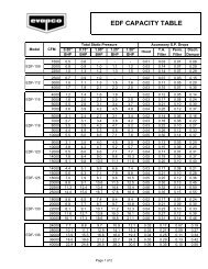
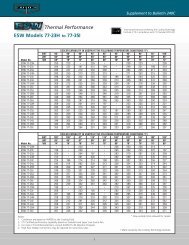
THERMAL PERFORMANCE – TWO (2) CELL COOLING TOWERS<br />
MODELS <strong>EDX</strong> 212-0122 THROUGH 214-1524 – TWO (2) CELL SELECTIONS<br />
To Make a Selection:<br />
Locate the column with the desired operating temperature conditions. Read down the column until you find the GPM equal to or greater than the<br />
flow required. Read horizontally to the left to find the model number of the unit that will perform the duty.<br />
TOWER CAPABILITY IN USGPM AT THE FOLLOWING TEMPERATURE CONDITIONS (°F)<br />
EWT 90° 95° 90° 95° 95° 90° 95° 95° 95° 100°<br />
Motor LWT 80° 80° 80° 80° 85° 80° 80° 85° 85° 85°<br />
Model No. Hp WB 68° 68° 70° 70° 70° 72° 72° 72° 75° 75°<br />
<strong>EDX</strong> 212-0122 (2) 40 5014 4045 4556 3680 6216 4077 3238 5799 5082 4134<br />
<strong>EDX</strong> 212-0222 (2) 30 5019 4044 4558 3678 6238 4076 3236 5812 5087 4134<br />
<strong>EDX</strong> 212-0322 (2) 40 5228 4222 4754 3840 6470 4256 3372 6039 5299 4316<br />
<strong>EDX</strong> 212-0422 (2) 50 5368 4338 4882 3950 6642 4372 3479 6200 5441 4433<br />
<strong>EDX</strong> 212-0522 (2) 40 5478 4424 4980 4027 6792 4458 3547 6334 5552 4521<br />
<strong>EDX</strong> 212-0622 (2) 50 5596 4527 5093 4120 6913 4563 3622 6455 5671 4627<br />
<strong>EDX</strong> 212-0722 (2) 60 5680 4597 5169 4189 7016 4633 3692 6553 5756 4697<br />
<strong>EDX</strong> 212-0822 (2) 50 5866 4746 5337 4324 7260 4783 3812 6774 5945 4849<br />
<strong>EDX</strong> 212-0922 (2) 60 5921 4798 5393 4370 7302 4836 3844 6822 5999 4902<br />
<strong>EDX</strong> 212-1022 (2) 60 6199 5022 5644 4578 7400 5061 4039 7151 6281 5131<br />
<strong>EDX</strong> 214-0124 (2) 25 4915 4083 4523 3762 6002 4111 3360 5609 4974 4161<br />
<strong>EDX</strong> 214-0224 (2) 25 5165 4261 4738 3913 6355 4291 3481 5924 5229 4345<br />
<strong>EDX</strong> 214-0324 (2) 30 5200 4327 4789 3988 6339 4356 3566 5928 5261 4408<br />
<strong>EDX</strong> 214-0424 (2) 30 5464 4516 5017 4150 6713 4547 3694 6261 5532 4604<br />
<strong>EDX</strong> 214-0524 (2) 40 5675 4732 5231 4366 6902 4764 3908 6459 5741 4820<br />
<strong>EDX</strong> 214-0624 (2) 40 5963 4938 5479 4542 7308 4972 4048 6821 6035 5033<br />
<strong>EDX</strong> 214-0724 (2) 50 6080 5080 5610 4691 7380 5114 4203 6911 6150 5174<br />
<strong>EDX</strong> 214-0824 (2) 40 6278 5270 5805 4877 7578 5304 4383 7110 6348 5365<br />
<strong>EDX</strong> 214-0924 (2) 50 6384 5297 5872 4876 7809 5333 4350 7294 6461 5398<br />
<strong>EDX</strong> 214-1024 (2) 60 6425 5376 5932 4967 7787 5411 4453 7296 6499 5474<br />
<strong>EDX</strong> 214-1124 (2) 60 6751 5609 6214 5167 8245 5648 4613 7705 6832 5716<br />
<strong>EDX</strong> 214-1224 (2) 50 6716 5647 6215 5229 8093 5683 4704 7598 6791 5748<br />
<strong>EDX</strong> 214-1324 (2) 60 7106 5984 6580 5545 8548 6022 4992 8029 7184 6090<br />
<strong>EDX</strong> 214-1424 (2) 75 7183 5980 6617 5513 8700 6021 4927 8186 7268 6093<br />
<strong>EDX</strong> 214-1524 (2) 75 7560 6380 7007 5916 N.A. 6420 5332 8531 7643 6491<br />
TOWER CAPABILITY IN USGPM AT THE FOLLOWING TEMPERATURE CONDITIONS (°F)<br />
EWT 95° 100° 95° 97° 100° 102° 95° 96° 100° 102°<br />
Motor LWT 85° 85° 85° 87° 85° 85° 85° 86° 85° 85°<br />
Model No. Hp WB 76° 76° 78° 78° 78° 78° 80° 80° 80° 80°<br />
<strong>EDX</strong> 212-0122 (2) 40 4827 3896 4243 5033 3405 3189 3537 3994 2819 2682<br />
<strong>EDX</strong> 212-0222 (2) 30 4830 3895 4243 5038 3403 3187 3535 3993 2820 2686<br />
<strong>EDX</strong> 212-0322 (2) 40 5035 4067 4429 5248 3550 3320 3689 4170 2923 2774<br />
<strong>EDX</strong> 212-0422 (2) 50 5170 4180 4549 5389 3657 3427 3798 4285 3032 2885<br />
<strong>EDX</strong> 212-0522 (2) 40 5274 4262 4639 5498 3729 3494 3872 4369 3095 2948<br />
<strong>EDX</strong> 212-0622 (2) 50 5391 4362 4747 5617 3811 3566 3960 4471 3142 2983<br />
<strong>EDX</strong> 212-0722 (2) 60 5471 4431 4819 5701 3881 3638 4028 4541 3221 3066<br />
<strong>EDX</strong> 212-0822 (2) 50 5650 4574 4975 5888 4006 3756 4158 4688 3330 3173<br />
<strong>EDX</strong> 212-0922 (2) 60 5706 4624 5029 5943 4044 3786 4201 4739 3338 3171<br />
<strong>EDX</strong> 212-1022 (2) 60 5972 4841 5263 6222 4243 3980 4404 4961 3530 3365<br />
<strong>EDX</strong> 214-0124 (2) 25 4755 3953 4254 4931 3514 3315 3633 4039 2970 2842<br />
<strong>EDX</strong> 214-0224 (2) 25 4990 4120 4447 5182 3646 3432 3775 4213 3062 2925<br />
<strong>EDX</strong> 214-0324 (2) 30 5031 4190 4506 5217 3728 3518 3854 4280 3155 3019<br />
<strong>EDX</strong> 214-0424 (2) 30 5281 4368 4711 5483 3869 3643 4004 4466 3253 3109<br />
<strong>EDX</strong> 214-0524 (2) 40 5493 4584 4927 5693 4084 3857 4220 4682 3461 3314<br />
<strong>EDX</strong> 214-0624 (2) 40 5765 4778 5149 5983 4237 3993 4384 4884 3568 3411<br />
<strong>EDX</strong> 214-0724 (2) 50 5888 4923 5287 6100 4390 4148 4536 5027 3727 3570<br />
<strong>EDX</strong> 214-0824 (2) 40 6084 5111 5479 6297 4573 4327 4720 5216 3899 3739<br />
<strong>EDX</strong> 214-0924 (2) 50 6174 5127 5521 6406 4551 4291 4708 5239 3838 3670<br />
<strong>EDX</strong> 214-1024 (2) 60 6223 5211 5593 6446 4650 4396 4803 5320 3951 3785<br />
<strong>EDX</strong> 214-1124 (2) 60 6531 5431 5845 6773 4825 4551 4990 5549 4074 3896<br />
<strong>EDX</strong> 214-1224 (2) 50 6511 5479 5869 6737 4906 4644 5062 5590 4188 4017<br />
<strong>EDX</strong> 214-1324 (2) 60 6891 5807 6217 7127 5205 4930 5369 5924 4448 4268<br />
<strong>EDX</strong> 214-1424 (2) 75 6952 5792 6229 7207 5152 4862 5326 5917 4356 4168<br />
<strong>EDX</strong> 214-1524 (2) 75 7334 6193 6625 7583 5557 5266 5731 6317 4756 4565<br />
Note: For alternate selections and conditions other than those stated, consult your EVAPSPEC II selection program or local EVAPCO representative.<br />
4
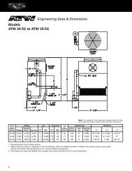
ENGINEERING DATA AND DIMENSIONS<br />
Note: Do not use this drawing as a certified print.<br />
Dimensions are subject to change.<br />
<strong>EDX</strong> 212-0122 thru<br />
214-1524<br />
(2)4” Overflow<br />
(2)2” Drain<br />
MODELS <strong>EDX</strong> 212-0122 THRU 214-1524 – TWO (2) CELL COOLING TOWERS<br />
Weights (LBS) DIMENSIONS CONNECTIONS<br />
Heaviest Fan Air Water Water Make<br />
<strong>EDX</strong> Section Motor Flow Inlets Outlet Up<br />
Model No. Shipping Operating (Upper)(1) HP (CFM) L W H (2) M B F P (3) (4) (5)<br />
212-0122 35950 70250 10740 (2) 40 355920 23' 11-1/2” 22' 2” 16' 9-3/4” 11' 10” 6' 8-7/16” 16' 3-11/16” 11' 1” (4) 8” (2) 12” (2) 2”<br />
212-0222 40000 82180 11250 (2) 30 376900 23' 11-1/2” 22' 2” †22' 8-5/8” 11' 10” 10' 7-11/16” 22' 2-1/2” 11' 1” (4) 8” (2) 12” (2) 2”<br />
212-0322 37450 74370 10740 (2) 40 381920 23' 11-1/2” 22' 2” 18' 9-3/8” 11' 10” 8' 8-1/16” 18' 3-5/16” 11' 1” (4) 8” (2) 12” (2) 2”<br />
212-0422 36180 70480 10850 (2) 50 383390 23' 11-1/2” 22' 2” 16' 9-3/4” 11' 10” 6' 8-7/16” 16' 3-11/16” 11' 1” (4) 8” (2) 12” (2) 2”<br />
212-0522 40340 82520 11420 (2) 40 414830 23' 11-1/2” 22' 2” †22' 8-5/8” 11' 10” 10' 7-11/16” 22' 2-1/2” 11' 1” (4) 8” (2) 12” (2) 2”<br />
212-0622 37680 74600 10850 (2) 50 411420 23' 11-1/2” 22' 2” 18' 9-3/8” 11' 10” 8' 8-1/16” 18' 3-5/16” 11' 1” (4) 8” (2) 12” (2) 2”<br />
212-0722 36400 70690 10960 (2) 60 407420 23' 11-1/2” 22' 2” 16' 9-3/4” 11' 10” 6' 8-7/16” 16' 3-11/16” 11' 1” (4) 8” (2) 12” (2) 2”<br />
212-0822 40580 82750 11530 (2) 50 446860 23' 11-1/2” 22' 2” †22' 8-5/8” 11' 10” 10' 7-11/16” 22' 2-1/2” 11' 1” (4) 8” (2) 12” (2) 2”<br />
212-0922 37890 74820 10960 (2) 60 437190 23' 11-1/2” 22' 2” 18' 9-3/8” 11' 10” 8' 8-1/16” 18' 3-5/16” 11' 1” (4) 8” (2) 12” (2) 2”<br />
212-1022 40790 82960 11640 (2) 60 474860 23' 11-1/2” 22' 2” †22' 8-5/8” 11' 10” 10' 7-11/16” 22' 2-1/2” 11' 1” (4) 8” (2) 12” (2) 2”<br />
214-0124 40530 83020 11830 (2) 25 346500 28' 1-1/2” 24' 2” 16' 9-5/8” 13' 11” 6' 8-7/16” 16' 4” 12' 1” (4) 10” (2) 14” (2) 3”<br />
214-0224 41980 87630 11830 (2) 25 371980 28' 1-1/2” 24' 2” 18' 9-1/4” 13' 11” 8' 8-1/16” 18' 3-5/8” 12' 1” (4) 10” (2) 14” (2) 3”<br />
214-0324 40670 83160 11900 (2) 30 368210 28' 1-1/2” 24' 2” 16' 9-5/8” 13' 11” 6' 8-7/16” 16' 4” 12' 1” (4) 10” (2) 14” (2) 3”<br />
214-0424 42120 87780 11900 (2) 30 395290 28' 1-1/2” 24' 2” 18' 9-1/4” 13' 11” 8' 8-1/16” 18' 3-5/8” 12' 1” (4) 10” (2) 14” (2) 3”<br />
214-0524 41010 83500 12070 (2) 40 405270 28' 1-1/2” 24' 2” 16' 9-5/8” 13' 11” 6' 8-7/16” 16' 4” 12' 1” (4) 10” (2) 14” (2) 3”<br />
214-0624 42460 88120 12070 (2) 40 435070 28' 1-1/2” 24' 2” 18' 9-1/4” 13' 11” 8' 8-1/16” 18' 3-5/8” 12' 1” (4) 10” (2) 14” (2) 3”<br />
214-0724 41270 83760 12190 (2) 50 436560 28' 1-1/2” 24' 2” 16' 9-5/8” 13' 11” 6' 8-7/16” 16' 4” 12' 1” (4) 10” (2) 14” (2) 3”<br />
214-0824 46430 98430 12930 (2) 40 473220 28' 1-1/2” 24' 2” †22' 8-1/2” 13' 11” 10' 7-11/16” 22' 2-13/16” 12' 1” (4) 10” (2) 14” (2) 3”<br />
214-0924 42710 88370 12190 (2) 50 468660 28' 1-1/2” 24' 2” 18' 9-1/4” 13' 11” 8' 8-1/16” 18' 3-5/8” 12' 1” (4) 10” (2) 14” (2) 3”<br />
214-1024 41480 83970 12300 (2) 60 463920 28' 1-1/2” 24' 2” 16' 9-5/8” 13' 11” 6' 8-7/16” 16' 4” 12' 1” (4) 10” (2) 14” (2) 3”<br />
214-1124 42930 88580 12300 (2) 60 498030 28' 1-1/2” 24' 2” 18' 9-1/4” 13' 11” 8' 8-1/16” 18' 3-5/8” 12' 1” (4) 10” (2) 14” (2) 3”<br />
214-1224 46680 98680 13060 (2) 50 509760 28' 1-1/2” 24' 2” †22' 8-1/2” 13' 11” 10' 7-11/16” 22' 2-13/16” 12' 1” (4) 10” (2) 14” (2) 3”<br />
214-1324 46890 98890 13160 (2) 60 541700 28' 1-1/2” 24' 2” †22' 8-1/2” 13' 11” 10' 7-11/16” 22' 2-13/16” 12' 1” (4) 10” (2) 14” (2) 3”<br />
214-1424 43050 88700 12360 (2) 75 536490 28' 1-1/2” 24' 2” 18' 9-1/4” 13' 11” 8' 8-1/16” 18' 3-5/8” 12' 1” (4) 10” (2) 14” (2) 3”<br />
214-1524 47010 99010 13220 (2) 75 583530 28' 1-1/2” 24' 2” †22' 8-1/2” 13' 11” 10' 7-11/16” 22' 2-13/16” 12' 1” (4) 10” (2) 14” (2) 3”<br />
Notes: 1. Heaviest section weights include removable shipping skid weight of 900 lbs. per section for 12’ models and 1,200 lbs. per section for 14’ models.<br />
2. Height includes 7” fan guard. Those models with a † beside indicate fan guards ship loose for field mounting.<br />
3. Inlet connection includes 150# raised face flange and 125 PSI flanged butterfly valve for balancing and positive water shut off.<br />
4. Water outlet is standard with bevel for weld and grooved for a mechanical coupling. Alternate connections are available.<br />
5. Each make-up connection is standard male pipe thread. Overflow and drains are also male pipe thread as standard. Alternate connections are available.<br />
5
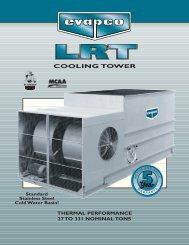
STRUCTURAL STEEL SUPPORT<br />
C<br />
3/4" MOUNTING HOLES<br />
1-1/8<br />
AIR<br />
INLET<br />
D<br />
AIR<br />
INLET<br />
UNIT OUTLINE<br />
E<br />
L<br />
AIR<br />
INLET<br />
D<br />
AIR<br />
INLET<br />
C<br />
UNIT OUTLINE<br />
A<br />
W<br />
1-1/8<br />
Shipping Operating<br />
Model No. Weight (Lbs) Weight (Lbs) L W A C D E<br />
<strong>EDX</strong> 212-0122 35950 70250 23' 11-1/2” 22' 2” 12' 10” 3-1/4” 11' 1-1/4” 5-3/4”<br />
<strong>EDX</strong> 212-0222 40000 82180 23' 11-1/2” 22' 2” 12' 10” 3-1/4” 11' 1-1/4” 5-3/4”<br />
<strong>EDX</strong> 212-0322 37450 74370 23' 11-1/2” 22' 2” 12' 10” 3-1/4” 11' 1-1/4” 5-3/4”<br />
<strong>EDX</strong> 212-0422 36180 70480 23' 11-1/2” 22' 2” 12' 10” 3-1/4” 11' 1-1/4” 5-3/4”<br />
<strong>EDX</strong> 212-0522 40340 82520 23' 11-1/2” 22' 2” 12' 10” 3-1/4” 11' 1-1/4” 5-3/4”<br />
<strong>EDX</strong> 212-0622 37680 74600 23' 11-1/2” 22' 2” 12' 10” 3-1/4” 11' 1-1/4” 5-3/4”<br />
<strong>EDX</strong> 212-0722 36400 70690 23' 11-1/2” 22' 2” 12' 10” 3-1/4” 11' 1-1/4” 5-3/4”<br />
<strong>EDX</strong> 212-0822 40580 82750 23' 11-1/2” 22' 2” 12' 10” 3-1/4” 11' 1-1/4” 5-3/4”<br />
<strong>EDX</strong> 212-0922 37890 74820 23' 11-1/2” 22' 2” 12' 10” 3-1/4” 11' 1-1/4” 5-3/4”<br />
<strong>EDX</strong> 212-1022 40790 82960 23' 11-1/2” 22' 2” 12' 10” 3-1/4” 11' 1-1/4” 5-3/4”<br />
<strong>EDX</strong> 214-0124 40530 83020 28' 1-1/2” 24' 2” 15' 4” 3-1/4” 13' 2-1/4” 5-3/4”<br />
<strong>EDX</strong> 214-0224 41980 87630 28' 1-1/2” 24' 2” 15' 4” 3-1/4” 13' 2-1/4” 5-3/4”<br />
<strong>EDX</strong> 214-0324 40670 83160 28' 1-1/2” 24' 2” 15' 4” 3-1/4” 13' 2-1/4” 5-3/4”<br />
<strong>EDX</strong> 214-0424 42120 87780 28' 1-1/2” 24' 2” 15' 4” 3-1/4” 13' 2-1/4” 5-3/4”<br />
<strong>EDX</strong> 214-0524 41010 83500 28' 1-1/2” 24' 2” 15' 4” 3-1/4” 13' 2-1/4” 5-3/4”<br />
<strong>EDX</strong> 214-0624 42460 88120 28' 1-1/2” 24' 2” 15' 4” 3-1/4” 13' 2-1/4” 5-3/4”<br />
<strong>EDX</strong> 214-0724 41270 83760 28' 1-1/2” 24' 2” 15' 4” 3-1/4” 13' 2-1/4” 5-3/4”<br />
<strong>EDX</strong> 214-0824 46430 98430 28' 1-1/2” 24' 2” 15' 4” 3-1/4” 13' 2-1/4” 5-3/4”<br />
<strong>EDX</strong> 214-0924 42710 88370 28' 1-1/2” 24' 2” 15' 4” 3-1/4” 13' 2-1/4” 5-3/4”<br />
<strong>EDX</strong> 214-1024 41480 83970 28' 1-1/2” 24' 2” 15' 4” 3-1/4” 13' 2-1/4” 5-3/4”<br />
<strong>EDX</strong> 214-1124 42930 88580 28' 1-1/2” 24' 2” 15' 4” 3-1/4” 13' 2-1/4” 5-3/4”<br />
<strong>EDX</strong> 214-1224 46680 98680 28' 1-1/2” 24' 2” 15' 4” 3-1/4” 13' 2-1/4” 5-3/4”<br />
<strong>EDX</strong> 214-1324 46890 98890 28' 1-1/2” 24' 2” 15' 4” 3-1/4” 13' 2-1/4” 5-3/4”<br />
<strong>EDX</strong> 214-1424 43050 88700 28' 1-1/2” 24' 2” 15' 4” 3-1/4” 13' 2-1/4” 5-3/4”<br />
<strong>EDX</strong> 214-1524 47010 99010 28' 1-1/2” 24' 2” 15' 4” 3-1/4” 13' 2-1/4” 5-3/4”<br />
Notes:<br />
1. These are suggested arrangements for preliminary layout purposes. Consult your EVAPCO representative for factory certified steel support drawings.<br />
2. The recommended support for the <strong>EDX</strong> Cooling Tower is structural “I” beams. The unit should be elevated to allow access underneath the unit and to the roof below.<br />
Mounting holes, 3/4” in diameter are located in the bottom flanges of the pan to provide for bolting to the structural steel.<br />
3. Beams should be sized in accordance with accepted structural practices. Maximum deflection of beam under unit to be 1/360 of the unit length, not to exceed 1/2”.<br />
4. Beams should be level before setting the unit in place. Do not level the unit by shimming between it and the “I” beams.<br />
5. Support beams and Anchor bolts are to be furnished by others.<br />
6. Dimensions, weights and data are subject to change without notice. Refer to the factory certified drawings for exact dimensions.<br />
7. For alternate layout arrangements please consult the factory. NOTE: OPTIONAL BOTTOM CONNECTIONS WILL REQUIRE THE UNIT TO BE ELEVATED TO ALLOW FOR PIPING.<br />
8. Each tie down location requires (2) two anchor bolts.<br />
9. For applications that require vibration rails or point isolation, consult the factory.<br />
6
MECHANICAL SPECIFICATIONS<br />
EVAPCO <strong>EDX</strong> Cooling Tower Mechanical Specifications<br />
with Optional Stainless Steel Construction and Maintenance Equipment<br />
Furnish and install factory assembled, induced draft, crossflow cooling towers as shown on plans. Total fan<br />
motor horsepower shall not exceed ________ HP, consisting of ________ @ ______ HP fan motors.<br />
1.0 Cooling Performance Capacity: The towers shall be guaranteed to cool ________ GPM of water from ________°F<br />
to ________°F at ________°F entering wet bulb temperature when installed as shown on plans.<br />
2.0 Hot Water Distribution: The towers shall be provided with stainless steel hot water basins. Each basin shall<br />
be provided with a 125 psi flanged butterfly valve to provide means of positive water shut-off to the tower<br />
and to balance flow between hot water basins and between tower cells. Anti-vortexing type polypropylene<br />
nozzles shall be provided to assure even water distribution over the heat transfer fill media. Heavy duty fiberglass<br />
hot water distribution basin covers shall be provided. Basin covers shall be a sliding design to allow easy<br />
inspection of hot water basins.<br />
3.0 Cold Water Basin: Cold water basins shall be constructed of G-235 galvanized steel and shall be provided with a side<br />
suction outlet connection for each basin. The outlet connections shall be beveled for welding and provided with a<br />
mechanical coupling groove. Each basin shall be provided with anti-vortexing hood, drain connection, overflow<br />
connection, Type 304 stainless steel strainers, and float operated mechanical make-up valve with plastic float. The<br />
basin floor sections under the fill shall be sloped from the louver face towards the depressed center section of the<br />
basin floor to deter build-up of contaminants under the fill and to facilitate basin cleaning.<br />
4.0 Air Inlet Louvers: Air inlet louvers shall be water containment design in order to minimize water splash out.<br />
Louvers shall be PVC construction molded integral with fill sheets in order to establish and maintain a contained<br />
water flow pattern on the fill sheets.<br />
5.0 Heat Transfer Surface: The heat transfer surface shall be PVC film type fill. The fill shall be elevated above<br />
the basin floor to allow basin cleaning under the fill area. The fill shall be bottom supported to prevent fill<br />
sagging and permanently assure easy and effective basin cleaning. Fill shall be stacked bundle design to allow<br />
easy removal for fill cleaning and/or replacement without cutting or removing fill supports.<br />
6.0 Drift Eliminators: Drift eliminators shall be PVC construction. The guaranteed maximum drift rate shall be<br />
0.002% of the design flow rate.<br />
7.0 Structure, Casing, Fan Deck and Fan Cylinders: Tower structure, casing, fan deck and fan cylinders shall be<br />
constructed from G-235 galvanized steel. During fabrication, all galvanized panel edges shall be coated with<br />
a 95% pure zinc-rich compound.<br />
8.0 Access: A large access door with minimum dimensions of 46” high and 32” wide shall be provided in the<br />
tower casing wall to permit entry into the tower cold water basin and fan plenum area. Access doors shall be<br />
hinged design for easy access.<br />
9.0 Fan Motors: Fan motors shall be mounted on an adjustable base which allows the motor to swing to the outside<br />
of the unit for servicing or replacement. Motors shall be ________ HP maximum, TEAO, 1.15 service factor,<br />
variable torque, ball bearing design and suitable for cooling tower duty. Motors shall be ________ (two<br />
speed/one speed), ________ RPM, single winding, ________ phase, ________ hertz, ________ volts.<br />
10.0 Drive: Fans shall be driven by a multi-groove, solid back type v-belt. The belt material shall be neoprene reinforced<br />
with polyester cord and specifically designed for cooling tower service. Fan and motor sheaves shall be<br />
cast aluminum construction. Belt adjustment shall be accomplished from the exterior of the unit. Bearing<br />
lube lines shall be extended to the exterior of the unit for easy maintenance.<br />
11.0 Fans: Each tower cell shall be provided with one heavy duty, statically balanced, propeller type fan. Fans shall<br />
utilize aluminum blades which are installed in a closely fitted fan cylinder with venturi air inlet for maximum<br />
fan efficiency. Each fan blade shall be individually adjustable. Fan cylinders shall be covered with a heavy<br />
gauge hot dip galvanized wire fan guard.<br />
7
MECHANICAL SPECIFICATIONS<br />
12.0 Fan Shaft Bearing: Fan shaft bearings shall be heavy duty self aligning ball type with grease fittings<br />
extended to outside of the unit. Bearings shall be designed for a minimum L-10 life of 75,000 hours<br />
(375,000 hour average life).<br />
13.0 Fan Drive Warranty: Fan motors and fan drive components shall be warranted against defects in<br />
materials and workmanship for a period of five (5) years from date of shipment. Drive components<br />
covered by this warranty shall include fans, belts, bearings, fan shafts, drive sheaves and fan motors.<br />
STAINLESS STEEL ALTERNATIVES<br />
Stainless Steel Cold Water Basins - In the first line of specification section 3.0, insert the words “stainless<br />
steel” in lieu of “G-235 galvanized steel”.<br />
Stainless Steel Hot Water Basins - Standard on the EVAPCO <strong>EDX</strong> cooling tower per specification section 2.0.<br />
Stainless Steel Towers - In the second line of specification section 7.0, insert the words “stainless steel” in lieu<br />
of “G-235 galvanized steel”. Delete the second sentence of specification section 7.0. In the first line of specification<br />
section 3.0, insert the words “stainless steel” in lieu of ”G-235 galvanized steel”.<br />
ACCESS AND MAINTENANCE OPTIONS<br />
Handrail and Ladder: The top of the tower shall be provided with perimeter handrailing and kneerail<br />
designed in accordance with OSHA guidelines. A ladder rising from the base of the tower to the top of the<br />
“handrail” shall be provided. The ladder shall be designed to attach to the tower casing wall. The ladder<br />
and handrailing shall ship loose for assembly and installation by the installing contractor.<br />
Ladder Safety Cage: A galvanized steel safety cage to surround the ladder shall be provided. The safety<br />
cage shall extend from the top of perimeter handrailing down to the point which allows approximately<br />
seven feet clear headroom from grade/roof level.<br />
Plenum Walkway: Provide a factory installed internal walkway which is located at an elevation just above<br />
the top of the cold water basin and extending from one end wall to the opposite endwall.<br />
Interior Mechanical Equipment Platform: Provide a factory installed internal platform which is located to<br />
permit access to tower's mechanical equipment. Provide an internal ladder rising from the plenum walkway<br />
to the elevated mechanical equipment platform. The internal ladder shall ship loose for installation by the<br />
installing contractor.<br />
Access Door Platform: (for elevated installations): Provide an access door platform at the base of the tower.<br />
The platform shall extend from the casing access door to the vertical ladder which is attached to the tower<br />
exterior casing. The platform shall be supported by a galvanized steel framework attached to the tower.<br />
The platform shall be surrounded by a handrail and kneerail. The access door platform shall ship loose for<br />
field assembly and installation by the installing contractor.<br />
External Motor Access Platform: Provide an external motor access platform at mid-elevation of the tower.<br />
The platform shall extend from the outside motor location to the vertical ladder which is attached to the<br />
tower exterior casing. The platform shall be supported by a galvanized steel framework attached to the<br />
tower. The platform shall be surrounded by a handrail and kneerail. The external motor access platform<br />
shall ship loose for assembly and installation by the installing contractor.<br />
8
OPTIONAL EQUIPMENT<br />
Single Side Inlet Connection<br />
The <strong>EDX</strong> is available with a Single Side Inlet option which eliminates<br />
external pipework, valves and field balancing associated<br />
with the standard (2) inlet design.<br />
Internal PVC pipework is utilized to relocate the water inlet to the<br />
side of each cell. The connection is standard with a hole and bolt<br />
circle pattern, other options are available. Note: Multiple cell<br />
installation will require adequate space between towers to allow<br />
for piping, unless the bottom inlet option is selected.<br />
If a tight, side by side layout is required, the <strong>EDX</strong> is available with<br />
an optional Bottom Inlet Connection. The inlet is located on the<br />
bottom of the cold water basin and allows the inlet pipework to<br />
run underneath the unit. Note: Adequate space is required<br />
underneath the unit for pipework. Please consult the factory for<br />
certified drawings indicating connection size and location.<br />
S<br />
K<br />
Model Static Single P Water Inlet* Water Outlet**<br />
No. Lift Inlet Height (Per Cell) (Per Cell)<br />
<strong>EDX</strong> 212-0122 17' 5” 8'-8-3/8” 11' 1” (1) 12” (1) 12”<br />
<strong>EDX</strong> 212-0222 23' 9-3/4” 14' 7-1/4” 11' 1” (1) 12” (1) 12”<br />
<strong>EDX</strong> 212-0322 19'- 4-1/2” 10' 8” 11' 1” (1) 12” (1) 12”<br />
<strong>EDX</strong> 212-0422 17' 5” 8' 8-3/8” 11' 1” (1) 12” (1) 12”<br />
<strong>EDX</strong> 212-0522 23' 9-3/4” 14' 7-1/4” 11' 1” (1) 12” (1) 12”<br />
<strong>EDX</strong> 212-0622 19' 4-1/2” 10' 8” 11' 1” (1) 12” (1) 12”<br />
<strong>EDX</strong> 212-0722 17' 5” 8' 8-3/8” 11' 1” (1) 12” (1) 12”<br />
<strong>EDX</strong> 212-0822 23' 9-3/4” 14' 7-/4” 11' 1” (1) 12” (1) 12”<br />
<strong>EDX</strong> 212-0922 19' 4-1/2” 10' 8” 11' 1” (1) 12” (1) 12”<br />
<strong>EDX</strong> 212-1022 23' 9-3/4” 14' 7-1/4” 11' 1” (1) 12” (1) 12”<br />
<strong>EDX</strong> 214-0124 17' 7-3/8” 8' 8-3/8” 12' 1” (1) 14” (1) 14”<br />
<strong>EDX</strong> 214-0224 19' 6-7/8” 10' 8” 12' 1” (1) 14” (1) 14”<br />
<strong>EDX</strong> 214-0324 17' 7-3/8” 8' 8-3/8” 12' 1” (1) 14” (1) 14”<br />
<strong>EDX</strong> 214-0424 19' 6-7/8” 10' 8” 12' 1” (1) 14” (1) 14”<br />
<strong>EDX</strong> 214-0524 17' 7-3/8” 8' 8-3/8” 12' 1” (1) 14” (1) 14”<br />
<strong>EDX</strong> 214-0624 19' 6-7/8” 10' 8” 12' 1” (1) 14” (1) 14”<br />
<strong>EDX</strong> 214-0724 17' 7-3/8” 8' 8-3/8” 12' 1” (1) 14” (1) 14”<br />
<strong>EDX</strong> 214-0824 24' 1/8” 14' 7-1/4” 12' 1” (1) 14” (1) 14”<br />
<strong>EDX</strong> 214-0924 19' 6-7/8” 10' 8” 12' 1” (1) 14” (1) 14”<br />
<strong>EDX</strong> 214-1024 17' 7-3/8” 8' 8-3/8” 12' 1” (1) 14” (1) 14”<br />
<strong>EDX</strong> 214-1124 19' 6-7/8” 10' 8” 12' 1” (1) 14” (1) 14”<br />
<strong>EDX</strong> 214-1224 24' 1/8” 14' 7-1/4” 12' 1” (1) 14” (1) 14”<br />
<strong>EDX</strong> 214-1324 24' 1/8” 14' 7-1/4” 12' 1” (1) 14” (1) 14”<br />
<strong>EDX</strong> 214-1424 19' 6-7/8” 10' 8” 12' 1” (1) 14” (1) 14”<br />
<strong>EDX</strong> 214-1524 24' 1/8” 14' 7-1/4” 12' 1” (1) 14” (1) 14”<br />
Notes:<br />
1. Use this chart for the pre-engineering phase of the project. Obtain factory certified drawings from your local EVAPCO representative or the factory.<br />
2. Pipework shown is provided by EVAPCO. Consult the factory certified drawings for dimensions.<br />
3. External pipework not shown must be provided by others and self-supported. Do not support pipework from the cooling tower.<br />
4. Note: The single inlet connection is located above the basin access door, position inlet piping properly to avoid blocking the door. Consult page 5 for<br />
dimensions of the unit.<br />
5. Consult the factory for optional bottom inlet connection.<br />
* Standard connection is hole and bolt circle design for 150# raised face flange.<br />
** Standard connection is Beveled for Weld and grooved for a mechanical coupling.<br />
Other Accessories/Optional Materials<br />
• Pony Motors<br />
• Bottom Sump Box<br />
• Gear Drive<br />
• Air Inlet Screens<br />
• Electric Water Level Controls and Level Indicators<br />
• Vibration Switch<br />
• Fan and Motor Davit<br />
• Flanged Connections<br />
• Flume Plate<br />
Models<br />
KW*<br />
<strong>EDX</strong> 212-0122 to 1022 (4) 12<br />
<strong>EDX</strong> 214-0124 to 1524 (4) 15<br />
Electric Pan Heaters<br />
9
E V A P C O P R O D U C T S A R E M A N U F A C T U R E D W O R L D W I D E<br />
World Headquarters/<br />
Research and<br />
Development Center<br />
EVAPCO Facilities<br />
EVAPCO...Taking Quality and Service to a Higher Level!<br />
World Headquarters<br />
Research/Development Center<br />
EVAPCO, Inc.<br />
P.O. Box 1300<br />
Westminster, MD 21158 USA<br />
Phone: (410) 756-2600<br />
Fax: (410) 756-6450<br />
E-Mail: marketing@evapco.com<br />
European Sales Offices<br />
EVAPCO France S.A.R.L.<br />
5 Rue des Cerisiers<br />
Z.I. De l’Eglantier<br />
F-91090 Lisses France<br />
Phone: (33) 1 6086-0508<br />
Fax: (33) 1 6086-3990<br />
EVAPCO Europe GmbH<br />
Bovert 22<br />
D-40670 Meerbusch, Germany<br />
Phone: (49) 2159-912367<br />
Fax: (49) 2159-912368<br />
E-Mail: info@evapco.de<br />
Asia/Pacific Headquarters<br />
EVAPCO Asia, Ltd.<br />
Suite D, 23rd/F, Majesty Building<br />
138 Pudong Ave<br />
Shanghai, China 200120<br />
Phone: (86) 21-5877-3980<br />
Fax: (86) 21-5877-2928<br />
E-Mail: evapco@online.sh.cn<br />
2M/0199/CL<br />
EVAPCO Manufacturing Facilities<br />
EVAPCO East<br />
5151 Allendale Lane<br />
Taneytown, MD 21787 USA<br />
Phone: (410) 756-2600<br />
Fax: (410) 756-6450<br />
E-Mail: marketing@evapco.com<br />
EVAPCO Midwest<br />
1723 York Road<br />
Greenup, IL 62428 USA<br />
Phone: (217) 923-3431<br />
Fax: (217) 923-3300<br />
E-Mail: evapco@rr1.net<br />
EVAPCO West<br />
1900 West Almond Ave.<br />
Madera, CA 93637 USA<br />
Phone: (559) 673-2207<br />
Fax: (559) 673-2378<br />
E-Mail: evapco@evapcowest.com<br />
Refrigeration Valves & Systems<br />
1520 Crosswind Dr.<br />
Bryan,TX 77808 USA<br />
Phone: (979) 778-0095<br />
Fax: (979) 778-0030<br />
E-Mail: rvs@mail.myriad.net<br />
EVAPCO Iowa<br />
925 Quality Drive<br />
Lake View, Iowa 51450 USA<br />
Regional Office<br />
Phone: (507) 446-8005<br />
Fax: (507) 446-8239<br />
E-Mail: evapcomn@mnic.net<br />
EVAPCO Europe N.V.<br />
Heersterveldweg 19<br />
Industriezone Tongeren-Oost<br />
3700 Tongeren, Belgium<br />
Phone (32) 12 395029<br />
Fax: (32) 12 238527<br />
E-Mail: evapco.europe@evapcp.be<br />
EVAPCO Europe, S.R.L.<br />
Via Ciro Menotti 10,<br />
I-20017 Passirana di Rho<br />
Milano, Italy<br />
Phone: (39) 02-939-9041<br />
Fax: (39) 02-935-00840<br />
E-Mail: evapcoeurope@evapco.it<br />
EVAPCO Europe S.R.L.<br />
Via Dosso, 2<br />
Piateda Sondrio, Italy 23020<br />
Air EVAPCO (Ltd)<br />
92 Asma Fami St.,ARD El-Golf<br />
Heliopolis, Cairo, Egypt<br />
Phone: (202) 290-7483<br />
Fax: (202) 290-0892<br />
E-Mail: manzlawi@egyptonline.com<br />
EVAPCO S.A. (Pty) Ltd.<br />
18 Quality Road<br />
Isando 1600<br />
Republic of South Africa<br />
Phone: (27) 11-392-6630<br />
Fax: (27) 11-392-6615<br />
E-Mail: evapco@icon.co.za<br />
Visit EVAPCO’s Website at: http://www.evapco.com<br />
Beijing-EVAPCO<br />
Refrigeration Equipment Co., Ltd.<br />
Yan Qi Industrial Development<br />
District<br />
Huai Rou County Beijing, P.R. China<br />
Code 101407<br />
Phone: (86) 10 6166-7238<br />
Fax: (86) 10 6166-7395<br />
E-Mail: beijing@evapco.com<br />
Shanghai Hezhong-EVAPCO<br />
Refrigeration Co., Ltd.<br />
855 Yang Tai Road<br />
Bao Shan Area<br />
Shanghai, P.R. China - Code 201901<br />
Phone: (86) 21 5680-5298<br />
Fax: (86) 21 5680-1545<br />
Aqua-Cool Towers<br />
34-42 Melbourne St.<br />
P.O. Box 436<br />
Riverstone, NSW Australia 2765<br />
Phone: (61) 29 627-3322<br />
Fax: (61) 29 627-1715<br />
Bulletin 700B