Single Case BiRotor Plus Manual - Brodie International
Single Case BiRotor Plus Manual - Brodie International
Single Case BiRotor Plus Manual - Brodie International

Create successful ePaper yourself
Turn your PDF publications into a flip-book with our unique Google optimized e-Paper software.
BI-SBRPLUS<br />
Revision 04<br />
July 2010<br />
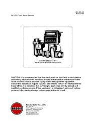
Model <strong>BiRotor</strong> <strong>Plus</strong><br />
Installation and Operation <strong>Manual</strong><br />
TM<br />
Engineering the Future<br />
1
Table of Contents<br />
1.0 Read Me First i<br />
2.0 Receipt of Shipment 1<br />
3.0 Return Shipment 1<br />
4.0 Storage 2<br />
5.0 Introduction 2<br />
6.0 Specifications 3<br />
7.0 <strong>BiRotor</strong> <strong>Plus</strong> Approvals 5<br />
8.0 Installation 5<br />
9.0 Maintenance 9<br />
10.0 Troubleshooting 13<br />
11.0 Parts List 15<br />
12.0 Model Code 17<br />
13.0 Approval Drawing 20<br />
14.0 Warranty Claim Procedures 19<br />
Decontamination Statement 20<br />
Notes 22<br />
Notes 23
1.0 Read Me First<br />
Notice<br />
<strong>Brodie</strong> <strong>International</strong>, a <strong>Brodie</strong> Meter Co., LLC Company (“<strong>Brodie</strong>”) shall not be liable for technical or<br />
editorial errors in this manual or omissions from this manual. <strong>Brodie</strong> makes no warranties, express or<br />
implied, including the implied warranties of merchantability and fitness for a particular purpose with<br />
respect to this manual and, in no event, shall <strong>Brodie</strong> be liable for any special or consequential damages<br />
including, but not limited to, loss of production, loss of profits, etc.<br />
Product names used herein are for manufacturer or supplier identification only and may be trademarks/<br />
registered trademarks of these companies.<br />
The contents of this publication are presented for informational purposes only, and while every effort has<br />
been made to ensure their accuracy, they are not to be construed as warranties or guarantees, expressed<br />
or implied, regarding the products or services described herein or their use or applicability. We reserve<br />
the right to modify or improve the designs or specifications of such products at any time.<br />
<strong>Brodie</strong> does not assume responsibility for the selection, use or maintenance of any product. Responsibility<br />
for proper selection, use and maintenance of any <strong>Brodie</strong> product remains solely with the purchaser and<br />
end-user.<br />
<strong>Brodie</strong> <strong>International</strong><br />
Statesboro, Georgia, USA<br />
All rights reserved. No part of this work may be reproduced or copied in any form or by any means -<br />
graphic, electronic or mechanical - without first receiving the written permission of <strong>Brodie</strong> <strong>International</strong>.,<br />
Statesboro, Georgia, USA.<br />
TM<br />
i
Essential Instructions General<br />
<strong>Brodie</strong> Meter Co., LLC designs, manufactures and tests its products to meet many international<br />
standards. As the instruments are sophisticated technical products they must be installed, used and<br />
maintained properly to ensure they continue to operate within their normal specifications. The<br />
following instructions must be adhered to and incorporated into onsite safety programs where<br />
possible.<br />
Read all instructions prior to installing, operating or servicing the product. If the instruction manual<br />
is not the correct one, telephone +1 912 489 0200. Retain the instruction manual for future<br />
reference.<br />
If you do not understand any of the instructions, contact your local <strong>Brodie</strong> representative for<br />
clarification.<br />
Follow all warnings, cautions and instructions marked on or supplied with the product. It is the end<br />
users responsibility to operate the instrument with in the specifications as defined with in the<br />
instruction manual or marked on the instruments name plates.<br />
Install the equipment as specified in the installation instructions of the appropriate manual and in<br />
accordance to local and national codes.<br />
To ensure proper performance, use qualified personnel to install, operate, program and maintain the<br />
product.<br />
Some types of equipment contain Carbon Steel, Cast Iron and/or Aluminium wetted parts, these<br />
instruments are not for use on water service.<br />
It is the end users responsibility to assess the surface temperature of the device when it is in service,<br />
and if required take the necessary precautions to avoid personnel injury or damage to other<br />
equipment.<br />
When replacement parts are required, ensure that qualified people use replacement parts specified<br />
by the manufacturer. Unauthorised parts and procedures can affect the products performance and<br />
place the safe operation of the process at risk. Look alike substitution may result in explosion, fire,<br />
electrical hazards, improper operation or personnel injury.<br />
Use of this equipment for any other purpose than it is intended for may result in property damage<br />
and/or serious personal injury or death.<br />
QA-500 (5/08)
Essential Instructions for Measuring Equipment Including the European<br />
Union (Directive 2004/22/EC MID)<br />
Although measurement transducers are not specifically included in the MID regulations as they<br />
do not form a complete measuring (system) instrument ref Article 1 and 4, Annex I and Annex<br />
MI-005. <strong>Brodie</strong> Meter Co., LLC implements the same stringent regulations for all products and<br />
tests to the same standards which are used for complete (systems) instruments.<br />
The complete system must contain all the necessary components to meet the requirements of<br />
the local regulations. These components may include, pumps, air eliminators, strainers, valves,<br />
flow computers, etc.<br />
The unit must be sealed in accordance with the local regulations; it is the end users<br />
responsibility to ensure this happens<br />
Flow measuring devices are provided with two labels which specify flow ranges. The name<br />
plate label which includes the factory serial number; details the operating flow range, this is<br />
the flow range the device will operate within without causing damage, and the custody<br />
transfer label; this label details the working flow range associated with a particular weights<br />
and measures approval. It should be noted that these may not be the same; therefore in trade<br />
applications the flow ranges specified on the custody transfer label should be followed.<br />
QA-501 (5/08)
Essential Instructions for Electrical Equipment Including the European<br />
Union (Directive 2004/108/EC and 2004/22/EC)<br />
This unit contains Electrostatic sensitive circuit boards. Electrostatic safety precautions should be<br />
taken to prevent damage.<br />
When connecting wiring, it is good practice to use shielded cable. The shield should be<br />
connected to earth at the read out or control systems end of the cable; the other end of the shield<br />
should not be connected. This wiring practice is mandatory in order to comply with the<br />
requirements for electromagnetic compatibility as per the EMC directive 2004/108/EC and MID<br />
2004/22/EC of the council of the European Union<br />
It is the end users responsibility to ensure that all protective covers are in place to prevent<br />
electrical shock and/or personnel injury.<br />
QA-502 (5/08)
Essential Instructions for Pressure Containing Equipment, Including the<br />
European Union (Directive 97/23/EC)<br />
When installing the equipment the bolting must conform to the requirements of ASME B16.5<br />
paragraph 5.3 and to the material requirements of ASME B16.5 Table 1B. Gaskets must conform<br />
to the requirements of ASME B16.20.<br />
Although it is not expected for the device to be used in a service where it would come in to<br />
contact with unstable fluids, it is the end users responsibility to assess any risks and take any<br />
precautions necessary.<br />
It is the end users responsibility to ensure that piping and other attachments connected to the<br />
<strong>Brodie</strong> instrument do not place adverse stresses upon it, the design of the instrument has not been<br />
assessed for the effects of traffic, wind or earthquake loadings.<br />
It is the end users responsibility to ensure that the instrument is mounted when required on suitable<br />
supporting foundations.<br />
It is the end users responsibility to install the device in a well designed system to avoid potential<br />
hazards such as water hammer, vacuum collapse or uncontrolled chemical reactions.<br />
It is the end users responsibility to provide fire protection measures and equipment in accordance<br />
with the local regulations.<br />
It is the end users responsibility to install suitable straining and air/gas elimination systems.<br />
The instrument has been designed without allowance for corrosion or other chemical attack. The<br />
end user should implement a periodic inspection and maintenance program to ensure that none of<br />
the instruments pressure containing components has been subject to any corrosion. It is possible to<br />
examine the instrument for evidence of corrosion through the inlet and the outlet.<br />
When the ambient temperature is below the minimum operating temperature specified on the<br />
device, it is the end users responsibility to ensure that the devise is warmed to an appropriated<br />
temperature before being pressurised.<br />
Do not exceed the operating pressure and temperature limits of the instrument as stamped on the<br />
nameplates.<br />
It is the customer’s responsibility to install this equipment in a system that provides adequate over<br />
pressure protection, and that limit pressure surges to 10% of the maximum allowable working<br />
pressure of the instrument.<br />
It is the end users responsibility to provide fire protection measures and equipment in accordance<br />
with the local regulations.<br />
QA-503 (5/08)
Essential Instruction When Equipments Is To Be Used In Hazardous<br />
Locations, Including the European Union (Directive 94/9/EC)<br />
Any Hazardous area approval applies to equipment without cable glands. When mounting the flameproof<br />
enclosure in a hazardous area only cable glands / conduit seals certified to meet or exceed the rating of<br />
the equipment should be used, refer to the type approval documentation for further details. It is the end<br />
users responsibility to ensure this happens.<br />
Cable glands and cable must be suitable for the operating temperature of the device under its rated<br />
conditions, this is especially important is the device has an operating temperature above 70 0 C (158 0 F)<br />
The meter has been provided with an approved sealing device in one of the cable entries, the other entry<br />
has been closed with a plastic cap plug. It is the end users responsibility to remove the cap plug and<br />
replace it with a suitable cable gland or conduit seal before the equipment is put into service.<br />
It is the end users responsibility to ensure when the instrument is located in a hazardous area that all Cable<br />
glands and conduit seals must be installed in accordance with the local codes and regulations.<br />
It is the end users responsibility to ensure that before opening an electronic enclosure in a flammable<br />
atmosphere; all the electrical circuits must be interrupted.<br />
If replacement of the screws which secure the sensor housing, the UMB cover of the electronic register and<br />
its cover are required, they must be replaced with either factory direct parts or M6-1 x 16 (6g) mm hex<br />
socket head screws of equal length. The screws must be made from stainless steel grade A1-70 or A2-70<br />
and be torqued to a value of 55 in lbs upon installation, its is the end users responsibility to ensure this<br />
happens.<br />
It is the end users responsibility to assess the maximum surface temperature of the device and the equipment<br />
the device is attached to and located next to as this may exceed the temperature ratings of the device itself.<br />
If this happens, additional safety precautions will need to be implemented by the end user.<br />
Flame proof housings contain Aluminium; although the composition of these enclosures is carefully<br />
maintained to prevent any risk of an ignition source it is the end users responsibility to ensure that the<br />
housing is not struck by rusty tools or objects.<br />
If the equipment is to be installed in an area where dust deposits and build up are to be expected, a<br />
maintenance plan should be arranged to include regular removal of the dust build up. This will prevent the<br />
dusts forming a possible source of ignition.<br />
The power supply requirements for this product are specified with in the operating and maintenance<br />
manual, it is the end users responsibility to operate the product with in these specified limits.<br />
The instrument contains surfaces that constitute flames paths, these surfaces should not contain any mars or<br />
scratches, and if any are present the factory or the local representative should be contacted immediately to<br />
obtain a new housing as the safety of the enclosure may be impaired. It is the end users responsibility to<br />
inspect these surfaces every time the enclosure is opened.<br />
When flanged flame paths are re assembled the gap between them should be less than 0.0015” (0.038<br />
mm) such that a ½” (12.5mm) wide feeler 0.0015” (0.038mm) gauge will not enter the gap more than<br />
1/8” (3mm). It is the end users responsibility to ensure this happens each time the enclosure is reassembled.<br />
QA-504 (7/08)
2.0 Receipt of Shipment<br />
When the instrument is received, inspect the<br />
outside of the packing case for any damage that<br />
may have occurred during shipment.<br />
Any damage incurred during shipment<br />
is the carrier’s responsibility and is<br />
not part of the factory warranty. If the<br />
packing case is damaged notify the<br />
carrier immediately and follow their claim<br />
procedures.<br />
If the packaging is undamaged locate the envelope<br />
containing the packing list, this will generally be<br />
on the outside of the box. Carefully remove all<br />
the contents from the packaging checking for any<br />
damage, Check the items off against the packing<br />
list for correct parts and quantities. If any items<br />
are incorrect or damage please contact your sales<br />
representative immediately, quoting the sales order<br />
reference number.<br />
3.0 Return Shipment<br />
If any item is returned to the factory, a returned<br />
material report (RMR) will need to be completed,<br />
The RMR forms can be obtained from the local<br />
sales representative or the <strong>Brodie</strong> Meter Co., LLC<br />
product service department.<br />
If an instrument has been used with process fluid,<br />
then in addition to the RMR a decontamination<br />
statement will also be required..<br />
A decontamination form is included in section 13<br />
of this manual.<br />
Note: When an instrument is being removed<br />
from service is must be thoroughly drained and<br />
any hazardous substances neutralised. Care must<br />
be taken to ensure any substance removed from<br />
the instrument is disposed of in accordance to the<br />
local regulations, Placing the instrument on its inlet<br />
flange will aid drainage.<br />
The process connections should be sealed to<br />
prevent any residual substances leaking from<br />
the meter during shipment. The type of seal will<br />
depend on the mode of transport, the local carrier<br />
should be contacted for details.<br />
Any item should be securely packed, the larger<br />
instruments should be mounted on wooden<br />
pallets or skids for shipment, The exterior of pallet<br />
mounted items should be protected but suitable<br />
means, such as a solid wooden crate.<br />
When packaging the instrument for return to<br />
the factory, make two copies of the RMR and<br />
decontamination statement, place one copy inside<br />
the packaging and one copy on the outside of the<br />
packaging,<br />
Any equipment returned to the factory with out<br />
the correct documentation will be returned to the<br />
sender at their own expense.<br />
Return shipping address:<br />
1<br />
<strong>Brodie</strong> <strong>International</strong><br />
Product Service Department<br />
19267 Hwy. 301 North<br />
Statesboro, GA 30461<br />
Phone: 001.912.489.0200<br />
Fax: 001.912.489.0294<br />
service@brodieintl.com
4.0 Storage<br />
<strong>Brodie</strong> <strong>International</strong> instruments are precision<br />
devices and should be handled and stored with<br />
care.<br />
The inlet and outlet covers should remain in the<br />
instrument until the unit is ready for installation.<br />
If extended storage is required it is recommend<br />
that the instrument be placed in an environmentally<br />
controlled warehouse, if this is not possible the<br />
instrument should be stored in a water proof lined<br />
wooden box, desiccant packs should be taped to<br />
the inside of the instrument end connections before<br />
they are sealed to reduce the effect of humidity,<br />
depending on the storage time is may also be<br />
preferable to use a compatible corrosion inhibitor.<br />
Care should be taken to remove any storage<br />
protection items before installing the instrument.<br />
If an instrument is removed from service for an<br />
extended period of time it should be flushed with<br />
an appropriate corrosion inhibitor before being<br />
place in long term storage as mentioned above.<br />
5.0 Introduction<br />
Description<br />
The <strong>Single</strong> <strong>Case</strong> <strong>BiRotor</strong> <strong>Plus</strong> is an extremely<br />
accurate single cased flow measuring<br />
devicedesigned primarily for, but not limited to,<br />
ethanol blending. It produces a high resolution<br />
signal which is directly proportional to the rate of<br />
liquid flow through the meter utilizing non-wetted<br />
pick-offs. These signals can be shaped by a simple<br />
internal pre-amplifier for transmission to ancillary<br />
equipment.<br />
The <strong>BiRotor</strong> <strong>Plus</strong> Meter utilizes the exclusive <strong>BiRotor</strong><br />
principle. There are no sliding, oscillating, or<br />
reciprocating parts.<br />
Principle of Operation<br />
The operation of the meter is embodied in<br />
the function of the measuring rotors; they are<br />
always dynamically balanced but hydraulically<br />
unbalanced during operation. The rotors have<br />
no metal to metal contact with each other or with<br />
the housing with in which they rotate. Clearances<br />
between moving components are maintained with<br />
timing gears.<br />
The <strong>BiRotor</strong> <strong>Plus</strong> is a positive displacement (PD)<br />
meter. A PD meter uses a mechanical principle<br />
that measures flow by continuously dividing the<br />
flowing stream into known volumetric segments,<br />
isolating those segments momentarily, and then<br />
returning them to the flowing stream while counting<br />
the number of displacements. This is a direct<br />
volume measurement, there is no inferred<br />
or software generated measurement.<br />
2
6.0 Specifications<br />
Materials of Construction<br />
Meter Housing:<br />
Measuring Unit<br />
A 351 GR CF8M<br />
(316 Stainless Steel)<br />
End Plates and Body: A 351 GR CF8M<br />
(316 Stainless Steel)<br />
Rotors/Rotor Shafts:<br />
Timing Gears:<br />
Bearings:<br />
Elastomers:<br />
UMB Housing*:<br />
* This part is not wetted.<br />
Electrical Details<br />
Aluminum Rotor, Anodizied<br />
17-4 PH Stainless Steel Shaft<br />
416 Stainless Steel<br />
Ceramic/Stainless Steel<br />
Viton A®, Low swell Nitrile,<br />
Viton F®, or Fluoro Silicon<br />
are standard<br />
(other options available)<br />
A356 T6 Cast Aluminium<br />
Pick off:<br />
Non Wetted Reluctance Type<br />
Sine Wave Amplitude: 40 mV P-P, min.<br />
Preamplifier:<br />
Supply Voltage:<br />
9 to 28 VDC<br />
Outputs (Jumper selectable):<br />
Square wave: 0 to 5 KHz<br />
5 V Powered Pulse: 0 – 5 VDC, 20 mA Max<br />
Variable Voltage Pulses:<br />
0 to Supply Voltage Less 5%<br />
70 mA max<br />
Open Collector:<br />
Max voltage: 30 VDC<br />
Max current: 125 mA<br />
Max power: 0.5 W<br />
Performance<br />
SB25X Linearity Standard Rotors<br />
+/- 0.15% Over Standard Flow Range<br />
+/- 0.25% Over Extended Flow Range<br />
Repeatability: +/- 0.02%<br />
Viscosity Range: 0.2 - 5 cP<br />
Operating Temperatures Limits:<br />
Dependant on pick off type and O-Ring<br />
seals used, see Table 1.<br />
To convert pressure drop value to the actual<br />
process fluid, use the following equation:<br />
ΔP A<br />
= (cP A<br />
) 0.25 X (SG A<br />
) 0.75 X ΔP m<br />
ΔP A<br />
= Pressure Drop on Actual Fluid in PSI<br />
cP A<br />
= Viscosity of Actual Fluid in cP<br />
SG A<br />
= Density of Actual Fluid in SG<br />
ΔP m<br />
= Pressure Drop on Mineral Spirits (See Figure<br />
3 on Page 6 for Reference.)<br />
Table 1: Operating Temperature Limits<br />
Pick Off<br />
Type<br />
Seal Material<br />
Minimum Operating Temp<br />
Maximum Operating Temp<br />
Degree F Degree C Degree F Degree C<br />
Standard Viton A -15 -25 167 75<br />
Standard Viton F -15 -25 167 75<br />
Standard Fluoro Silicon -40 -40 167 75<br />
High Temp Viton A 14 -10 230 110<br />
High Temp Viton F 14 -10 230 110<br />
High Temp Fluoro Silicon 14 -10 230 110<br />
3
Table 2: Maximum Working Pressure at<br />
100 deg F, 38 deg C<br />
Flange Ratings PSI Bar<br />
ANSI 150# 275 19<br />
DIN PN 16 196 13.5<br />
ANSI 300# 720 50<br />
DIN PN 40 490 33.8<br />
Table 3: Flow Ranges, Less than 5 CSTK<br />
(Greater than 5 CSTK, Consult Facotry)<br />
Meter<br />
Size<br />
DN50<br />
& 2”<br />
Flow Rate<br />
GPM BPH M 3 /HR L/MIN<br />
150 105 34 568<br />
30* 43* 6.8* 114*<br />
15** 22** 3.4** 57**<br />
Nominal<br />
K-Factor<br />
*Minimum Standard Flow Ranges<br />
** Minimum Extended Range Flow Ranges<br />
Table 4: Shipping Weights<br />
and Volume<br />
Model Size Unit Weight<br />
950 PUL/<br />
GAL<br />
+/- 10%<br />
(250<br />
PUL/Liter)<br />
7.0 <strong>BiRotor</strong> <strong>Plus</strong> Approvals<br />
Environmental<br />
NEMA 4X<br />
Type 4X<br />
IP 65<br />
OIML R117-1 Class H3<br />
Electromagnetic Emissions & Immunity<br />
EMC Industrial ( EN 61326) CE, European Union<br />
OIML R117-1 Class E2<br />
FCC 47 CFR Part 15<br />
ICES-003, Issue 4<br />
Hazardous Area Approvals<br />
Temp Ambient. -40 to 60°C, -40 to 140°F<br />
Class 1, Division 1, Group C, and D<br />
(CSA 221162) (Pending on 300#)<br />
ATEX<br />
CE 0359 II 2 G Ex d IIB T6…T4<br />
Certificate: (ITS08ATEX15842X)<br />
IEC Ex<br />
Ex d IIB T6 – T4<br />
(IEC Ex ITS 08.0021X)<br />
Graph 3: Hazardous Area Temperature<br />
Classification Chart (T Rating)<br />
SB251<br />
SB254<br />
2" ANSI 150#<br />
DN50 PN 16<br />
2” ANSI 300#<br />
DN50 PN 40<br />
Lb 75<br />
Kg 34<br />
Lb 76<br />
Kg 36<br />
4<br />
Weights and Measure<br />
NTEP<br />
OIML R117-1 (Pending)<br />
The Peoples Republic of China<br />
Measurement Canada<br />
MID Certified as a component for use with in a<br />
measuring system as agreed within WELMEC<br />
Pressure Equipment<br />
Under the EU Pressure Equipment Directive<br />
97/23/EC<br />
Rated as SEP for all ANSI and DIN versions<br />
Canadian Registration: (Pending)
8.0 Installation<br />
General Requirements<br />
The instrument should be mounted on a secure<br />
foundation, If vertically mounted provisions should<br />
be taken to ensure stability.<br />
The process piping should not place any undue<br />
stress on the instrument<br />
Precautions should be taken to ensure that thermal<br />
fluid expansion does not raise the line pressure<br />
above the maximum allowable working pressure of<br />
the instrument<br />
Process piping needs to be clean and free of any<br />
foreign matter.<br />
A strainer should be installed upstream of the<br />
instrument.<br />
If the process fluid is expected to contain entrained<br />
air, an air eliminator should be installed upstream<br />
of the instrument<br />
A flow limiting valve should be installed<br />
downstream of the instrument, this will maintain a<br />
back pressure and prevent excessive flow rates.<br />
Isolation valves should be located at either ends of<br />
the instrument run and a bypass section installed,<br />
this will facilitate ease of component removal when<br />
required and reduce loss of product.<br />
Interference<br />
The instrument should not be installed in a location<br />
where excessive vibration is expected.<br />
The instrument should not be located close to any<br />
electromagnetic fields, for example those produced<br />
by electric motors, transformers, solenoids etc.<br />
Either of these factors could induce a signal into<br />
the flow sensing pick off and interfere with the<br />
measurement.<br />
Figure 1: <strong>Single</strong> <strong>Case</strong> <strong>BiRotor</strong> <strong>Plus</strong> Dimensions<br />
SB251<br />
SB254<br />
A B C<br />
in 6 12 9/16 10 3/8<br />
mm 152 319 264<br />
in 6 1/2 12 9/16 10 5/8<br />
mm 165 319 270<br />
5
Figure 2: Typical Installation<br />
Figure 3: Pressure Drop<br />
6
Installing the Instrument<br />
Refer to Figure 2 for typical installations.<br />
Remove the inlet and outlet protection covers.<br />
Install the instrument in to the pipe work using<br />
suitable hardware as specified in the local codes<br />
and regulations, ensure that the connections are<br />
made tight and torqued to the correct values.<br />
Connections the instrument wiring, refer to Figure<br />
3 or Figure 4. Cable entry into the electrical<br />
enclosure is by two 3/4-14 NPT threads.<br />
Use wiring appropriate for the location and<br />
operating conditions, If the instrument is being<br />
installed in a hazardous area wiring glands and/<br />
or conduits must conform to the local electrical<br />
code regulations.<br />
Note: For additional requirements on installation<br />
please refer to the essential instruction at the<br />
beginning of this manual.<br />
Figure 4: Wiring Connections<br />
Attachment to Additional Accessories<br />
If the instrument is being used with additional<br />
accessories, the instructions for these accessories<br />
should be read and understood before continuing<br />
with the installation. The output signal from the<br />
preamplifier, if one is fitted can be altered to<br />
interface with most electronic accessories. This is<br />
accomplished by the use of jumpers on the circuit<br />
board, Table 6 shows their configurations.<br />
Table 6: Input Settings<br />
Jumper<br />
J1 (Channel A)<br />
J2 (Channel B)<br />
Table 7: Output Settings<br />
Jumper<br />
Open<br />
Collector<br />
Position<br />
B<br />
B<br />
5 VDC<br />
Pulse<br />
V<br />
Supply<br />
Pulse<br />
J3 (Channel A) OUT A B<br />
J4 (Channel B) OUT A B<br />
Integral <strong>Brodie</strong> Electronic Rate Totalizer<br />
(BERT)<br />
If the instrument has been supplied with an integral<br />
Figure 5: Wiring Connections<br />
Preamplifier Fitted<br />
1 = V Supp 9-28 Vdc<br />
2 = V Comm<br />
3 = Channel A Signal<br />
4 = Channel A & B Common<br />
5 = Channel B Signal<br />
No Preamplifier Fitted<br />
7
electronic register, the internal connection wiring<br />
will already be in place. For additional functions<br />
and wiring possibilities please refer to the BERT’s<br />
instruction manual, BI-BERT.<br />
Start up and Operation<br />
Review the system to ensure all the components are<br />
in proper sequence, all isolation valves are closed,<br />
all electrical connections are complete and all<br />
covers are in place.<br />
To Pressurize the System<br />
Slowly open the inlet valve so as to prevent system<br />
shock. Slowly allow product to enter the system<br />
while keeping the downstream isolation valve<br />
closed.<br />
Open the down stream valve (10 percent) to allow<br />
any air to be flushed from the system. Do not over<br />
speed the instrument.<br />
Once the air has been flushed from the system<br />
close the down stream isolation valve, and check<br />
for any leaks. If any leaks are found check seals<br />
and retighten connections.<br />
To pressurize the system fully open the upstream<br />
isolation valve.<br />
Flow Start Up<br />
Once the system is pressurized:<br />
Turn on all electronic circuits and check function.<br />
Open flow control valves and allow the instrument<br />
to run at 20% of its rated flow for a minimum of 5<br />
minutes.<br />
During this initial run in, check all other<br />
components in the system for functionality.<br />
Once this run in is complete set the flow control<br />
valve to the required flow, ensure that the maximum<br />
flow for the instrument is not exceeded.<br />
Higher Temperature Start Up<br />
On higher temperature service above 212 Deg F,<br />
100 Deg C, ( based on an ambient of 70 Deg F,<br />
21 Deg C) special start-up procedures are required<br />
to prevent damage to the flowmeter components.<br />
The following equation may be used to determine<br />
the approximate flowmeter warm up time. A similar<br />
procedure should be followed on any thermal<br />
8<br />
shock in excess of 176 Deg F, 80 Deg C.<br />
Warm up time ( Hrs) = [Nom Connection Size (in)<br />
X (Oper temp (Deg F) – 212)]/100<br />
During this warm up time the meter should be<br />
operated at approx 5% of Max flow to allow the<br />
temperature to stabilize.<br />
Custody Trasnfer<br />
If the instrument is being used for custody transfer<br />
applications, A meter factor will need to be<br />
established under the actual operating conditions.<br />
This initial proving run should be carried out<br />
following the completion of the meter start up and<br />
in accordance with the local regulations.<br />
Note: There are no user adjustable parts in these<br />
instruments, however the instrument housing is<br />
provided with holes to facilitate sealing if required<br />
by the local weights and measures regulations.<br />
Performance Considerations<br />
The instrument will give many years of consistent<br />
performance with little need for maintenance<br />
or service. There are however several<br />
recommendations which if followed will further<br />
extend the instruments service life.<br />
The instrument should be kept filled with the<br />
process fluids it is measuring. This prevents the<br />
exposure to any product vapor, which in the case<br />
of petroleum products are more corrosive than their<br />
liquids. In addition this also prevents the formation<br />
and build up of deposits or gums which would<br />
cause increased mechanical friction.<br />
The instrument should always be kept free of water,<br />
keeping it full of the process fluid will accomplish<br />
this, but if this is not possible a regular inspection<br />
program should be set up and any water drained<br />
from the measuring system.<br />
Filter and strainers baskets should be cleaned<br />
frequently; debris and foreign matter are the<br />
biggest cause of meter wear and damage.<br />
All other associated equipment within the system<br />
should be regularly maintained and checked for<br />
functionality.<br />
Maintenance Considerations<br />
The amount of maintenance necessary for efficient
instrument performance is dependant on many<br />
factors; some of these are listed below.<br />
Continuity of Operation: An instrument that<br />
operates continuously will required more<br />
attention than one used intermittently<br />
Working flow rate: The life of the instrument is<br />
proportional to the speed of its operation. If the<br />
instrument is operating at or near to its maximum<br />
flow rate it will have a shorter life expectancy<br />
than if it were operating at its minimum flow<br />
rate.<br />
Lubricity: The lower the lubrication properties of<br />
the fluid being measured then the lower the life<br />
expectance will be.<br />
Cleanliness: A product contaminated with abrasive<br />
particulate will accelerate the wear of the<br />
instrument.<br />
9.0 Maintenance<br />
Notes:<br />
If instrument is being used in a hazardous area, all<br />
instructions on the labels and in this manual must<br />
be followed before the start of any maintenance.<br />
If the instrument is removed from the process line,<br />
the line should be sealed with suitable blanking<br />
flanges to prevent any possible leakage of product.<br />
WARNING: The internal measuring<br />
element contains closely meshed moving<br />
parts, care should be taken not to insert<br />
fingers into the rotors or timing gears as<br />
this will cause injury.<br />
Electronics<br />
9<br />
The instrument can be provided with up to<br />
two inductive pick off sensors and an optional<br />
preamplifier.<br />
Maintenance of the electronics does not require the<br />
system line pressure to be drained or the instrument<br />
to be removed from the system.<br />
ESD precautions must be followed.<br />
Removal/Replacement of Circuit Boards<br />
1. Disconnect all power to the instrument.<br />
2. Remove the electronics lid (36), or electronic<br />
register if one is fitted by undoing 4 Allen<br />
screws item (32).<br />
3. Disconnect terminals and wiring to the circuit<br />
board.<br />
4. Remove circuit board (37) by undoing the<br />
screws that attach it to the housing.<br />
To re-assemble reverse the removal instructions,<br />
Torque the 4 Allen screws (32) to 55 in-lb.<br />
Removal/Replacement of Pick-off Sensors<br />
1. Remove the circuits boards as detailed above.<br />
2. Remove the center screw (32) from the sensor<br />
housing (26) and lift off the hold down washer<br />
(30).<br />
3. Lift out the inductive sensor/s (28) and spring<br />
(29).<br />
The pick off should have resistance of 1000<br />
+/-15% Ohms resistance between the leads and<br />
10 M Ohms between the leads and the sensor<br />
housing when installed. If this is not the case the
pick off should be replaced.<br />
To reassemble, replace the pick off into the sensor<br />
housing, If only one pick-off is present it should<br />
be inserted in the hole labelled A. Secure with the<br />
hold down washer (30) and Allen screw (32) and<br />
replace the circuit board (37).<br />
Mechanical<br />
Removal of the Measuring Unit from the<br />
Process Line<br />
1. Disconnect all power to the instrument.<br />
2. Relieve all system pressure and drain the<br />
meter.<br />
3. Disconnect all external wiring form the<br />
electronics unit.<br />
4. Unbolt the instrument form the process<br />
piping and remove to a work shop for further<br />
disassembly. Care should be exercised to<br />
prevent the intrusion of foreign material into the<br />
instrument end connections.<br />
the disassembly.<br />
3. Remove the pulse wheel (4) by removing the<br />
screw (1) and washer (2) and retaining washer<br />
(3).<br />
4. Remove the screws (5) from end plate (7) at<br />
the timing gear (18 and 19) end of measuring<br />
assembly.<br />
A flat head screw driver may be used in<br />
conjunction with the slots on the endplate to aid<br />
in its removal; Excessive force is not required.<br />
5. Use a plastic or rubber mallet and strike<br />
the rotor shafts at the pulse wheel end of the<br />
housing to aid in removal of the rotor assembly.<br />
Figure 6: Measuring Unit Disassembly<br />
Removing the Measuring Element from the<br />
End Connections<br />
1. Turn the meter on end so that it stands in its<br />
inlet flange ( this will also finalize draining).<br />
2. Remove nuts (22) and lift off the outlet housing<br />
(21).<br />
3. Holding the measuring unit assembly, carefully<br />
lift straight up until the assembly clears the inlet<br />
housing. Place the measuring unit assembly in<br />
the horizontal position.<br />
At this stage the assembly can be inspected for<br />
wear or damage, If the assembly had jammed<br />
it may also be possible to unblock the rotors by<br />
flushing with cleaning solvent or kerosene with out<br />
the need for further disassembly.<br />
Disassembly of the Measuring Unit for<br />
Inspection and Cleaning<br />
Disassembling of the measuring unit can be<br />
achieved by two methods, removal of the<br />
mechanism while maintaining the clearance<br />
settings or complete disassembly.<br />
Disassembly While Maintaining the<br />
Clearance Setting<br />
1. Remove o-rings (12) from measuring element<br />
assembly.<br />
2. Place a folded rag between the timing gears<br />
(18 and 19) to prevent the rotors turning during<br />
10<br />
Once the rotor assembly has been removed from<br />
the housing any blockages or foreign material can<br />
be cleaned away.<br />
At this stage the meter can be reassembled<br />
reversing the disassembly procedure without the<br />
need to reset any clearances. Note: all elastomers<br />
that have been removed should be replaced with<br />
new parts during reassembly<br />
Complete Disassembly<br />
Continuing from part 4 above.<br />
1. Restrict the rotor movement by placing a<br />
folded rag between the timing gears (18 and<br />
19).<br />
2. Undo nuts (22), then remove them from the<br />
rotor shafts. The timing gears (18 and 19) can<br />
be released from the shaft by striking them on<br />
the flat surface with a plastic or rubber mallet.
3. Remove the rotors (10 and 11) from the end<br />
plate by gently tapping the rotor shafts with a<br />
plastic or rubber mallet. Remove the o-rings (9)<br />
from the rotor shafts.<br />
4. The bearings (8) can be removed from the<br />
end plates by pressing on the inner race of the<br />
bearings from the outside of the plate. If the<br />
bearings are removed from the endplates, they<br />
must be replaced.<br />
5. Remove the other end plate (7) from the<br />
measuring element housing (17) and remove<br />
bearings (8).<br />
Complete Reassembly<br />
1. Ensure all parts are clean and free of debris.<br />
2. Lubricate all bearings with a light oil, Note all<br />
o-rings should be replace with new ones during<br />
reassembly, all o-rings should be lubricated<br />
with a compatible lubrication compound.<br />
3. Press bearings (8) in to the end plates (7), use<br />
a hand press and ensure that the bearing is<br />
pressed on the outer race to avoid damage.<br />
The bearing races should be flush with the<br />
bottom of the end plate once the bearings have<br />
been pressed in correctly. The outer race of<br />
an old bearing can be used to assist in proper<br />
seating.<br />
4. Attach one end plate (7) to the measuring unit<br />
body outlet (17) (the outlet end is the right hand<br />
side of the measuring unit housing when the<br />
nameplate lable (14) is facing towards you).<br />
Align the dowel pin and gently tap into place<br />
with a plastic mallet. Once fully seated secure<br />
the end plate with screws (5).<br />
Each rotor (10 and 11) and timing gear (18<br />
and 19) is marked with a R or an L, During<br />
Figure 7: Rotor/Gear Orientation<br />
assembly the inscriptions need to be matched.<br />
(To orientate the rotors during assembly lay the<br />
measuring unit housing (17) on it’s side so that<br />
the name plate label (14) in on the bottom and<br />
the outlet end facing away from you. Then with<br />
the tapered ands of the rotors also facing away<br />
from you, the right hand rotor (11) goes in the<br />
right hand cavity and the left hand rotor (10)<br />
goes in the left hand cavity)<br />
5. Lubricate O-rings (9) and install on the rotor<br />
shafts. Mesh the two rotors together (10 and<br />
11) ensuring that the tapered shafts are at<br />
the same ends. The rotors should be held<br />
together with the tapered end of the shaft<br />
facing the end plate which is attached to the<br />
measuring element housing. While keeping the<br />
rotors meshed and even, insert them into the<br />
measuring chamber, use a plastic or rubber<br />
mallet to gently seat the rotor shafts into the<br />
bearings.<br />
6. Install the other end plate (7) and screws<br />
(5) on to the other end of measuring element<br />
body, ensure that the rotor shafts seat within the<br />
bearings.<br />
7. Place the timing gears (18 and 19) onto the<br />
respective tapered rotor shaft.<br />
8. Install the lock nuts (20) on to the rotor<br />
shafts, tighten these only finger tight until the<br />
clearances have been correctly set. Refer to the<br />
setting clearance section.<br />
9. Replace the pulse wheel (4) on the right hand<br />
rotor, Use thread locking compound on the<br />
threads and secure with the retaining washer<br />
(3) , washer (2) and screw (1).<br />
10. Install the o-rings (12) onto the main housing<br />
(17).<br />
11. Lower the complete measuring unit assembly<br />
into the inlet housing (21), align the dowel pin<br />
(6) and ensure it is fully located.<br />
12. Insert studs (21) into the four holes in the<br />
measuring unit housing (17) loosely attached<br />
four nuts (22) to the studs (21) at the inlet side.<br />
13. Lower the outlet housing (2 onto the main<br />
housing (17), the dowel pin (6) is used to<br />
ensure correct location. Avoid damage to the<br />
O-rings.<br />
14. Complete the assembly be securing all the<br />
nuts (22) and tightening them to the required<br />
torque value.<br />
Torque (150#, 300#, PN16, PN40 - 43 ft-lbs.)<br />
11
Setting Clearances<br />
1. Restrict the gear movement by placing a<br />
folded rag between the timing gears (18 and<br />
19).<br />
2. Tighten the nut (20) of the right hand timing<br />
gear (19) to a torque setting of 35 in-lbs.<br />
3. Loosen the nut (20) of the left hand timing<br />
gear (18).<br />
4. Place 0.003” shims in front and behind the<br />
tooth of the left hand rotor (10). Once the shims<br />
are in place and with the rotor movement still<br />
restricted tighten the nut (20) on the left hand<br />
timing gear (18) to a torque of 35 in-lbs ft-lbs.<br />
5. Remove the shims and folded rag. Check to<br />
rotors for correct clearance by rotating them.<br />
The rotors should turn freely and not make<br />
contact at any point, listen for sounds of the<br />
rotors touching.<br />
6. If the rotors bind or make noise repeat the<br />
procedure but this time loosen the right hand<br />
timing instead of the left.<br />
12
10.0 Troubleshooting<br />
This information has been provided as an aid to basic troubleshooting. Disassembly procedures<br />
have been outlined in section 9 of this manual. If the <strong>BiRotor</strong> <strong>Plus</strong> is found to be in need of repair it is<br />
recommended the user contact the nearest <strong>Brodie</strong> <strong>International</strong> Service Office or Representative. It is<br />
important that servicing be performed by trained and qualified personnel.<br />
Condition A: No Pulse Output is Present<br />
Probable Cause:<br />
1. No flow through meter.<br />
2. Improper electrical connection.<br />
3. Insufficient voltage to the preamplifier (if fitted).<br />
4. Power failure.<br />
5. Meter rotors jammed with debris.<br />
6. Damaged pickoff/amplifier board.<br />
Corrective Actions:<br />
1. Ensure the pipe line has flow.<br />
2. Ensure proper wiring connections have been made.<br />
3. Supply sufficient voltage to the preamplifier board, see specifications in Section 6.<br />
4. Ensure power is connected to the device and all it associated ancillaries.<br />
5. Remove debris from rotors (check for damage to rotors, timing gears and bearings).<br />
6. Replace pickoffs/preamplifier board.<br />
Condition B: Erratic or Non Uniform Pulse Signal<br />
Probable Cause:<br />
1. Improper electrical connection.<br />
2. Insufficient or fluctuating voltage to the preamplifier board (if fitted).<br />
3. Improper ground or shielding of connection cable.<br />
4. Power failure/damaged pickoffs or circuit board.<br />
5. Damaged/worn bearings or timing gears.<br />
Corrective Actions<br />
1. Ensure proper wiring connections have been made.<br />
2. Supply sufficient voltage to the preamplifier board, see specifications Section 6.<br />
3. Replace and/or wiring ground and shield.<br />
4. Ensure power supply is functioning or pickoffs/board as required.<br />
5. Replace bearings or timing gears.<br />
13
This page left blank intentionally.<br />
14
11.0 Parts List<br />
Figure 9: Exploded View of <strong>Single</strong> <strong>Case</strong> <strong>BiRotor</strong> <strong>Plus</strong>, Model SB25X<br />
15
Table: Parts List <strong>Single</strong> <strong>Case</strong> <strong>BiRotor</strong> <strong>Plus</strong>, Model B251<br />
Item Model B251 Description Quantity<br />
1 151098-419 Screw 1<br />
2 151881 Washer 1<br />
3 56033 Lock Button 1<br />
4 56031-043 Pulse Wheel 1<br />
5 151098-419 Screw 8<br />
6 154046 Dowel Pin 4<br />
7 56825-050 End Plate 2<br />
8*<br />
1500937-001 Bearings, Stainless Steel<br />
1500937-001CER<br />
Bearings, Ceramic<br />
4<br />
9* 152066-( ) See note 2 O-Ring 4<br />
10 56276-000 LH Rotor 1<br />
11 56286-000 RH Rotor 1<br />
12* 157361-( ) See note 2 O-Ring 2<br />
17<br />
56211-050M Measuring Unit Housing, MTR’s<br />
56211-050N Measuring Unit Housing, MTR’s and NACE<br />
1<br />
18 56291 LH Timing Gear See note 1<br />
19 56296 RH Timing Gear See note 1<br />
20 1500942 Stop Nut 2<br />
56819-100M Outlet Housing, 150# ANSI, MTR’s<br />
56819-100N Outlet Housing, 150# ANSI, MTR’s and NACE<br />
21<br />
56819-040M Outlet Housing, DIN PN 16 and PN 40, MTR’s<br />
56819040N<br />
Outlet Housing, DIN PN 16 and PN 40, MTR’s and NACE<br />
1<br />
56819-300M Outlet Housing, 300# ANSI, MTR’s<br />
56819-300N Outlet Housing, 300# ANSI, MTR’s and NACE<br />
22*<br />
151555-419M Hex Nut, MTR’s<br />
151555-419N Hex Nut, MTR’s and NACE<br />
8<br />
23*<br />
1500941M<br />
Stud, MTR’s<br />
1500941N<br />
Stud, MTR’s and NACE<br />
4<br />
56818-100M Inlet Housing,150# ANSI, MTR’s<br />
56818-100N Inlet Housing,150# ANSI, MTR’s and NACE<br />
26<br />
56818-040M Inlet Housing, DIN PN 16 and PN 40, MTR’s<br />
56818-040N Inlet Housing, DIN PN 16 and PN 40, MTR’s and NACE<br />
1<br />
58818-300M Inlet Housing,300# ANSI, MTR’s<br />
58818-300N Inlet Housing,300# ANSI, MTR’s and NACE<br />
27* 1500093-026 Weather Seal 1<br />
28*<br />
899-00-201-00 Pick Off, Standard<br />
899-00-201-01 Pick Off, High Temp<br />
1<br />
29 1500418 Spring 1<br />
30 86030-001 Hold Down 1<br />
32* 151496M Umb Screws 9<br />
36 CC-219Z-633-EBG Umb Cover 1<br />
37*<br />
230-00-300-00 Pre Amp Board<br />
230-10-300-50 Terminal Board<br />
1<br />
39 CA-375Z-259-XXA Umb Gasket 1<br />
41 899-00-100-00 Umb Housing 1<br />
42* 1500909D Approved Stopping Plug 1<br />
43 SD442 Plastic Cap Plug 1<br />
Notes:<br />
*Items marked with a * are recommended spare parts.<br />
1. These items are only available as a matched set, part number W56296.<br />
2. O-ring material suffix is as follows:<br />
-022 : Viton A<br />
-026 : Viton F<br />
-016 : FluoroSilicon<br />
3. When ordering the following information must be provided: Part number, Model Number, Serial<br />
Number, and Quantity Required. This information is necessary for items marked C/F (Consult Factory).<br />
16
12.0 Model Code<br />
17
13.0 Approval Drawing<br />
18
14.0 Warranty Claim Procedures<br />
1. Limited Warranty:<br />
Subject to the limitations contained in Section 2 herein and except as otherwise expressly provided<br />
herein, <strong>Brodie</strong> <strong>International</strong>, a <strong>Brodie</strong> Meter Co., LLC Company (“<strong>Brodie</strong>”) warrants that the firmware<br />
will execute the programming instructions provided by <strong>Brodie</strong>, and that the Goods-manufactured or<br />
Services provided by “<strong>Brodie</strong>” will be free from defects in materials or workmanship under normal use<br />
and care until the expiration of the applicable warranty period. Goods are warranted for twelve (12)<br />
months from the date of initial installation or eighteen (18) months from the date of shipment by “<strong>Brodie</strong>”,<br />
whichever period expires first. Consumables and Services are warranted for a period of 90 days from<br />
the date of shipment or completion of the Services. Products purchased by “<strong>Brodie</strong>” from a third party for<br />
resale to Buyer (“Resale Products”) shall carry only the warranty extended by the original manufacturer.<br />
Buyer agrees that “<strong>Brodie</strong>” has no liability for Resale Products beyond making a reasonable commercial<br />
effort to arrange for procurement and shipping of the Resale Products. If Buyer discovers any warranty<br />
defects and notifies “<strong>Brodie</strong>” thereof in writing during the applicable warranty period, “<strong>Brodie</strong>” shall, at<br />
its option, promptly correct any errors that are found by “<strong>Brodie</strong>” in the firmware or Services, or repair<br />
or replace F. O. B. point of manufacture that portion of the Goods or firmware found by “<strong>Brodie</strong>” to be<br />
defective, or refund the purchase price of the defective portion of the Goods/Services. All replacements<br />
or repairs necessitated by inadequate maintenance, normal wear and usage, unsuitable power sources,<br />
unsuitable environmental conditions, accident, misuse, improper installation, modification, repair, storage<br />
or handling, or any other cause not the fault of “<strong>Brodie</strong>” are not covered by this limited warranty, and<br />
shall be at Buyer’s expense. “<strong>Brodie</strong>” shall not be obligated to pay any costs or charges incurred by<br />
Buyer or any other party except as may be agreed upon in writing in advance by an authorized “<strong>Brodie</strong>”<br />
representative. All costs of dismantling, reinstallation and freight and the time and expenses of “<strong>Brodie</strong>’s”<br />
personnel for site travel and diagnosis under this warranty clause shall be borne by Buyer unless<br />
accepted in writing by “<strong>Brodie</strong>”. Goods repaired and parts replaced during the warranty period shall be<br />
in warranty for the remainder of the original warranty period or ninety (90) days, whichever is longer.<br />
This limited warranty is the only warranty made by <strong>Brodie</strong> and can be amended only in a writing signed<br />
by an authorized representative of “<strong>Brodie</strong>”. Except as otherwise expressly provided in the Agreement,<br />
THERE ARE NO REPRESENTATIONS OR WARRANTIES OF ANY KIND, EXPRESS OR IMPLIED, AS TO<br />
MERCHANTABILITY, FITNESS FOR PARTICULAR PURPOSE, OR ANY OTHER MATTER WITH RESPECT<br />
TO ANY OF THE GOODS OR SERVICES. It is understood that - corrosion or erosion of materials is not<br />
covered by our guarantee.<br />
2. Limitation Of Remedy And Liability:<br />
<strong>Brodie</strong> <strong>International</strong>, a <strong>Brodie</strong> Meter Co., LLC Company (“<strong>Brodie</strong>”) Shall Not Be Liable For Damages<br />
Caused By Delay In Performance. The Sole And Exclusive Remedy For Breach Of Warranty Hereunder<br />
Shall Be Limited To Repair, Correction, Replacement Or Refund Of Purchase Price Under The Limited<br />
Warranty Clause In Section 1 Herein. In No Event, Regardless Of The Form Of The Claim Or Cause Of<br />
Action (Whether Based In Contract, Infringement, Negligence, Strict Liability, Other Tort Or Otherwise),<br />
Shall “<strong>Brodie</strong>’s” Liability To Buyer And/Or Its Customers Exceed The Price To Buyer Of The Specific<br />
Goods Manufactured Or Services Provided By <strong>Brodie</strong> Giving Rise To The Claim Or Cause Of Action.<br />
Buyer Agrees That In No Event Shall <strong>Brodie</strong>’s Liability To Buyer And/Or Its Customers Extend To Include<br />
Incidental, Consequential Or Punitive Damages. The Term “Consequential Damages” Shall Include, But<br />
Not Be Limited To, Loss Of Anticipated Profits, Loss Of Use, Loss Of Revenue And Cost Of Capital.<br />
19
Decontamination Statement<br />
RMA Number:<br />
Item Being Returned:<br />
List all chemicals and process fluids and gasses that have come in contact with the equipment including<br />
cleaning agents. Attach additional pages of information if necessary. A Material Safety<br />
Data Sheet (MSDS) is required if non-food grade products have been used with the item being<br />
returned.<br />
Information Required Product 1 Product 2<br />
Chemical Name<br />
Health and Safety Hazards<br />
Precautions, First Aid<br />
I hereby certify the equipment being returned has been cleaned and decontaminated in accordance<br />
with good industrial practices and in compliance with OSHA and DOT regulations. This<br />
equipment poses no health or safety risks due to contamination.<br />
Signature:<br />
Name (Please Print):<br />
Title:<br />
Company Name:<br />
Phone Number:<br />
Fax:<br />
E-mail:<br />
Reason for Return:<br />
Reminder:<br />
All items being returned must be packaged separately. This decontamination statement and the<br />
MSDS sheet(s) must be placed on the outside of the shipping container.<br />
20<br />
19267 Highway 301 North (30461)<br />
PO Box 450 • Statesboro, GA 30459-0450<br />
Phone: 001.912.489.0200 • Fax: 001.912.489-0294<br />
www.brodieintl.com
This page left blank intentionally.<br />
21
Notes<br />
22
Notes<br />
23
TM<br />
Engineering the Future<br />
<strong>Brodie</strong> <strong>International</strong><br />
19267 Highway 301 North • Statesboro, GA 30461<br />
Phone: 001.912.489.0200 • Fax: 001.912.489.0294<br />
A <strong>Brodie</strong> Meter Co., LLC Company<br />
www.brodieintl.com<br />
The contents of this publication are presented for informational purposes only, and while every effort has been made to ensure their accuracy, they are not to<br />
be construed as warranties or guarantees, express or implied, regarding the products or services described herein or their use or applicability. <strong>Brodie</strong> Meter<br />
Co., LLC reserves the right to modify or improve the designs or specifications of such products at any time without notice.