CyberScan 600 Series Instruction Manual - Eutech
CyberScan 600 Series Instruction Manual - Eutech
CyberScan 600 Series Instruction Manual - Eutech

Create successful ePaper yourself
Turn your PDF publications into a flip-book with our unique Google optimized e-Paper software.
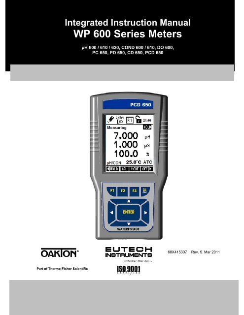
Integrated <strong>Instruction</strong> <strong>Manual</strong><br />
WP <strong>600</strong> <strong>Series</strong> Meters<br />
pH <strong>600</strong> / 610 / 620, COND <strong>600</strong> / 610, DO <strong>600</strong>,<br />
PC 650, PD 650, CD 650, PCD 650<br />
68X415307 Rev. 5 Mar 2011<br />
Technology Made Easy ...<br />
Part of Thermo Fisher Scientific
*IMPORTANT – PLEASE READ BEFORE YOU CONTINUE*<br />
PLEASE USE THIS MANUAL IN THIS ORDER :<br />
Step 1:<br />
Use the first half of this manual “General Guide” and “Temperature” to set up and<br />
calibrate your instrument (Pages 1 - 39).<br />
Step 2:<br />
Then go to the specific parameter guides (eg. pH, Conductivity, TDS etc) which are<br />
relevant to the model you have purchased. (Pg 41 onwards).<br />
CAUTION: Do not skip the general guide as your meter will not be configured to read<br />
accurately if your set-up and calibrations are not done accordingly.<br />
Thank you for reading this page. Please proceed.
Table of Contents<br />
GENERAL GUIDE.................................................................................... 1<br />
1. Overview For All Meters ......................................................................................... 3<br />
1.1 About the Meters ............................................................................................................................ 3<br />
1.1.1 Display Overview ................................................................................................................. 3<br />
1.1.2 Key Functions ...................................................................................................................... 3<br />
1.2 Inserting Batteries ........................................................................................................................... 4<br />
1.2.1 Inserting batteries for the first time ....................................................................................... 4<br />
1.2.2 Changing batteries subsequently ......................................................................................... 4<br />
1.3 Attaching the Belt ........................................................................................................................... 5<br />
1.4 Connecting Peripherals .................................................................................................................. 6<br />
1.4.1 Probes (pH/Conductivity/DO) ............................................................................................... 6<br />
1.4.2 Protective Rubber Boot ........................................................................................................ 7<br />
2. System Setup Mode For All Meters ....................................................................... 8<br />
2.1 About Setup Mode .......................................................................................................................... 8<br />
2.2 Accessing Setup mode ................................................................................................................... 8<br />
2.3 Setup Selection: System Settings ................................................................................................... 9<br />
2.4 Accessing Setup mode when password protection enabled ..........................................................15<br />
2.5 Modifying Setup parameters ..........................................................................................................16<br />
3. Calibration Mode For All Meters .......................................................................... 17<br />
3.1 About Calibration ...........................................................................................................................17<br />
3.2 About Conductivity/ Resistivity/ TDS/ Salinity Calibration ..............................................................17<br />
3.3 Preparing the Meter for Calibration ................................................................................................17<br />
3.4 Accessing Calibration mode ..........................................................................................................19<br />
3.4.1 Accessing Calibration mode when password protection enabled ........................................19<br />
4. Measurement Mode For All Meters ..................................................................... 21<br />
4.1 About Measurement Mode ............................................................................................................21<br />
4.1.1 Accessing functions ............................................................................................................21<br />
4.2 Taking Measurements ...................................................................................................................22<br />
4.2.1 Prepare the meter for measurement ...................................................................................22<br />
4.2.2 Taking a reading .................................................................................................................22<br />
4.2.3 Stable reading indicator ......................................................................................................23<br />
4.2.4 Holding a reading ................................................................................................................23<br />
4.3 Automatic Temperature Compensation (ATC) ...............................................................................23<br />
4.3.1 <strong>Manual</strong> Temperature Compensation (MTC) ........................................................................23<br />
4.4 Alarm set point (For pH/conductivity/DO) ......................................................................................24<br />
4.5 Calibration Due (CAL-DUE) Indicator (For pH/conductivity/DO) ....................................................24<br />
5. TRANSFERRING AND PRINTING DATA ............................................................. 24<br />
5.1 CyberComm <strong>600</strong> Data Acquisition Software ..................................................................................24<br />
5.2 Working with Memory functions – Auto Data Logging ....................................................................24<br />
5.2.1 Logging data automatically in the meter’s memory .............................................................25<br />
5.2.2 Storing a current measurement (In IrDA and LED print mode: Applicable to all modes) .....25<br />
5.2.3 Viewing stored data ............................................................................................................25<br />
5.2.4 Transferring stored data to the Computer (CyberComm) through IrDA ...............................26<br />
5.2.5 Transferring stored data to a PC not equipped with infrared receiver. ................................27<br />
5.2.6 Transferring stored data to a PC using an USB/ irDA Dongle. ............................................28<br />
6. Technical Specifications ...................................................................................... 29<br />
7. Accessories ........................................................................................................... 33<br />
8. Warranty & Return Policy ..................................................................................... 34<br />
8.1 Warranty ……. ...............................................................................................................................34<br />
8.2 Return of Goods ............................................................................................................................34<br />
8.3 Guidelines for Returning Unit for Repair ........................................................................................35
TEMPERATURE .................................................................................... 36<br />
1. Temperature Setup ............................................................................................... 38<br />
2. Temperature Calibration ...................................................................................... 38<br />
2.1 About Temperature Calibration ......................................................................................................38<br />
2.2 Temperature Calibration for ATC mode .........................................................................................39<br />
2.3 Temperature Calibration for MTC mode ........................................................................................40<br />
3. Temperature Measurement .................................................................................. 40<br />
pH.. ......................................................................................................... 42<br />
1. pH Setup ................................................................................................................. 44<br />
2. pH Calibration ........................................................................................................ 45<br />
2.1 About pH Calibration .....................................................................................................................45<br />
2.2 pH buffer group for calibration and auto-recognition ......................................................................46<br />
2.2.1 pH Calibration points ...........................................................................................................46<br />
2.3 pH Calibration with a Standard Buffer ............................................................................................46<br />
2.3.1 To start pH Calibration: .......................................................................................................46<br />
2.4 pH Calibration with a User-defined Buffer ......................................................................................48<br />
2.5 Calibration Report ..........................................................................................................................49<br />
2.5.1 To View Calibration Report: ................................................................................................49<br />
2.6 Average Slope Indicator of pH Probe ............................................................................................50<br />
3. pH Measurement Mode ......................................................................................... 50<br />
3.1 Resolution of pH Reading ..............................................................................................................50<br />
3.2 Indicators in pH measurement screen ...........................................................................................51<br />
mV ......................................................................................................... 52<br />
1. mV Setup Mode ..................................................................................................... 54<br />
2. mV Calibration Mode ............................................................................................ 54<br />
2.1 mV Calibration with a Standard ORP Calibration Solution .............................................................54<br />
2.2 Calibration Report ..........................................................................................................................55<br />
2.2.1 To View Calibration Report: ................................................................................................55<br />
3. mV Measurement Mode ........................................................................................ 55<br />
3.1 Indicators in mV measurement mode ............................................................................................55<br />
ION ......................................................................................................... 58<br />
1. Ion Setup ................................................................................................................ 60<br />
2. Ion Calibration Mode ............................................................................................. 60<br />
2.1 About Ion Calibration .....................................................................................................................60<br />
2.2 Calibration Report ..........................................................................................................................62<br />
2.2.1 To View Calibration Report .................................................................................................62<br />
3. Ion Measurement Mode ........................................................................................ 63<br />
3.1 Changing unit of measurement ......................................................................................................63<br />
3.2 Indicators in Ion measurement mode .............................................................................................63<br />
CONDUCTIVITY..................................................................................... 64<br />
1. Conductivity Setup ............................................................................................... 66<br />
2. Conductivity Calibration Mode ............................................................................ 68<br />
2.1 Conductivity Calibration mode .......................................................................................................68<br />
2.1.1 Conductivity calibration points .............................................................................................68<br />
2.2 Cell constant 68<br />
2.3 Normalization Temperature (°C) ....................................................................................................68<br />
2.4 Linear temperature Coefficient ......................................................................................................68<br />
2.5 Pure Water Coefficient ..................................................................................................................69<br />
2.6 To begin Calibration ......................................................................................................................69<br />
2.7 <strong>Manual</strong> Calibration .........................................................................................................................70<br />
2.8 Automatic Calibration (For Conductivity Calibration)......................................................................70
2.9 Calibration Report ..........................................................................................................................72<br />
2.9.1 To View Calibration Report: ................................................................................................72<br />
3. Conductivity Measurement Mode ........................................................................ 72<br />
3.1 Indicators in Conductivity measurement screen ............................................................................72<br />
TDS ........................................................................................................ 75<br />
1. TDS Setup .............................................................................................................. 77<br />
2. TDS Calibration Mode ........................................................................................... 79<br />
2.1 TDS Calibration Report .................................................................................................................80<br />
2.1.1 To View Calibration Report: ................................................................................................80<br />
3. TDS Measurement Mode ...................................................................................... 81<br />
3.1 Indicators in TDS measurement mode ..........................................................................................81<br />
4. About TDS .............................................................................................................. 82<br />
4.1 Calculating TDS Conversion Factor ...............................................................................................82<br />
4.2 Calculating Temperature Coefficients ............................................................................................82<br />
SALINITY ............................................................................................... 83<br />
1. Salinity Setup ........................................................................................................ 85<br />
2. Salinity Calibration Mode ..................................................................................... 86<br />
2.1 Salinity Calibration Report .............................................................................................................88<br />
2.1.1 To View salinity Report: ......................................................................................................88<br />
3. Salinity Measurement Mode ................................................................................. 89<br />
3.1 Indicators in salinity measurement mode .......................................................................................89<br />
RESISTIVITY ......................................................................................... 91<br />
1. Resistivity Setup ................................................................................................... 93<br />
2. Resistivity Calibration Mode ................................................................................ 95<br />
2.1 Resistivity Calibration Report .........................................................................................................96<br />
2.1.1 To View Calibration Report: ................................................................................................96<br />
3. Resistivity Measurement Mode ........................................................................... 97<br />
3.1 Indicators in Resistivity measurement mode ..................................................................................97<br />
DISSOLVED OXYGEN .......................................................................... 99<br />
PART A - % Saturation Mode ............................................................. 101<br />
1. O2 % - DO Saturation Setup .............................................................................. 101<br />
2. DO Calibration in % Saturation Mode (with ATC) ............................................ 103<br />
2.1 About DO(%) and DO (mg/L) Calibration ..................................................................................... 103<br />
2.2 To calibrate 100% saturation ....................................................................................................... 103<br />
2.3 To calibrate 0% saturation ........................................................................................................... 105<br />
2.3.1 % DO Calibration Report .................................................................................................. 106<br />
2.3.2 To View Calibration Report: .............................................................................................. 106<br />
2.4 % Saturation Offset Adjustment ................................................................................................... 107<br />
2.5 Set barometer pressure range and barometric pressure units ..................................................... 107<br />
2.6 Pressure compensation ............................................................................................................... 107<br />
3. Percentage Saturation (%) Measurement Mode .............................................. 107<br />
3.1 Indicators in percentage saturation measurement mode ............................................................. 107<br />
PART B – Concentration (mg/L) (ppm) Mode .................................. 108<br />
1. O2 mg/L (ppm) – DO Concentration Setup ....................................................... 108<br />
2. DO Calibration in mg/L mode or ppm Concentration mode ........................... 111<br />
2.1 Concentration Calibration Report ................................................................................................ 112<br />
2.1.1 To View Calibration Report: .............................................................................................. 112<br />
2.2 Set Salinity…. .............................................................................................................................. 113
2.2.1 Auto Salinity Compensation .............................................................................................. 113<br />
3. Concentration in Measurement Mode ............................................................... 113<br />
3.1 Indicators in concentration measurement screen ........................................................................ 113<br />
3.2 Dissolved Oxygen Probe ............................................................................................................. 114<br />
3.2.1 Dissolved Oxygen Principle .............................................................................................. 114<br />
3.2.2 Probe Care ....................................................................................................................... 115<br />
3.2.3 Membrane Housing Replacement ..................................................................................... 115<br />
3.2.4 Membrane/O-ring Replacement (Optional Procedure) ...................................................... 116<br />
3.2.5 Electrolyte Solution ........................................................................................................... 117
GENERAL GUIDE<br />
This section is applicable to all models of the<br />
WP <strong>600</strong> <strong>Series</strong> Meters. Please do not skip this<br />
section.<br />
Model<br />
Parameters<br />
pH <strong>600</strong><br />
Temperature (with ATC), pH (-2.00 to 20.00 measuring range).<br />
pH 610 Temperature (with ATC), pH (expandable resolution to 0.001).<br />
pH 620 Temperature (with ATC), pH (expandable resolution to 0.001)<br />
and Ion.<br />
COND <strong>600</strong><br />
COND 610<br />
DO <strong>600</strong><br />
PC 650<br />
PD 650<br />
CD 650<br />
PCD 650<br />
Temperature (with ATC), Conductivity, TDS.<br />
Temperature (with ATC), Conductivity, TDS, Salinity,<br />
Resistivity.<br />
Temperature (with ATC), Dissolved Oxygen (% & ppm).<br />
Temperature (with ATC), pH, mV, Ion, Conductivity, TDS,<br />
Salinity, Resistivity.<br />
Temperature (with ATC), pH, mV, Ion, Dissolved Oxygen (% &<br />
ppm).<br />
Temperature (with ATC), Conductivity, TDS, Salinity,<br />
Resistivity, Dissolved Oxygen (% & ppm).<br />
Temperature (with ATC), pH, mV, Ion, Conductivity, TDS,<br />
Salinity, Resistivity, Dissolved Oxygen (% & ppm).<br />
1
1. Overview For All Meters<br />
1.1 About the Meters<br />
SPECIAL FEATURES<br />
• Displays and measures up to 4 parameters simultaneously<br />
• Automatic temperature compensation<br />
• Built in memory backup to save calibration and 500 sets of measured data<br />
• Data logging feature date-and-time stamp to meet Good Laboratory Practice (GLP)<br />
• Data transmission through IrDA or RS232 through LED<br />
• User-selectable ‘CAL-DUE’ and set point alarm functions<br />
• Power source and Battery level indicator<br />
• Designed to work either from mains power or battery and automatically detect and switch to<br />
mains if available<br />
• Waterproof casing<br />
• User-configurable password protection for calibration & setup data<br />
• Intuitive on-screen messages appear to assist user<br />
1.1.1 Display Overview<br />
Indicators Used in Header Area<br />
Power Source & Battery Level<br />
Conductivity range of the probe<br />
Power Source: DC Adapter<br />
Average slope of the pH probe<br />
Data Transmission mode: LED<br />
Current Time in 24 Hour format<br />
Data Transmission mode: Infrared<br />
Data Logging Mode: Internal<br />
Memory<br />
Password Protection: Disabled<br />
Password Protection: Enabled<br />
1.1.2 Key Functions<br />
Key<br />
Function<br />
• Selects the function shown (in the display) just above the<br />
key. (For ON key, press and hold for 3 seconds.<br />
• Navigates to next available functions<br />
• Increment/decrement values in Setup & Calibration modes.<br />
• Navigates to sub groups in Setup selection screen.<br />
• In Setup mode, confirms selection or modified values<br />
• In Calibration mode, confirms calibration points or modified<br />
values<br />
3
1.2 Inserting Batteries<br />
NOTE: Please ensure that the gasket is in place otherwise the instrument will<br />
not be waterproof.<br />
Power up your meter using either:<br />
1. Four ‘AA’ size 1.5 V alkaline batteries (supplied) or,<br />
2. 9V DC power adapter (Optional in some models).<br />
1.2.1 Inserting batteries for the first time<br />
1. Use a Phillips screw driver to remove the four screws holding the battery<br />
cover.<br />
2. Insert the batteries in the right direction.<br />
3. Replace the battery cover and screws. Note the ▲UP symbol marked on the<br />
cover.<br />
4. Press the ON (F4) key. Hold the key down until the display appears.<br />
5. Set the system date & time before you start operating the meter for the first<br />
time.<br />
1.2.2 Changing batteries subsequently<br />
1. Connect the adapter before changing the batteries.<br />
2. If DC adapter is not available, switch off the meter and change the<br />
batteries within 30 seconds to avoid resetting the clock. This prevents the<br />
system time from resetting automatically.<br />
4
1.3 Attaching the Belt<br />
To attach the safety belt:<br />
1. Use a Phillips screw driver to remove the four screws holding the battery<br />
cover.<br />
2. Insert the safety belt through the two slots as indicated below.<br />
3. Screw the battery cover back on. Note the ▲UP symbol marked on the<br />
cover.<br />
4. Insert your palm between the belt and the body of the meter and adjust the<br />
hook & loop fastener.<br />
Note the correct side<br />
of the belt<br />
Battery Cover<br />
Hook & Loop<br />
fastener<br />
5
1.4 Connecting Peripherals<br />
1.4.1 Probes (pH/Conductivity/DO)<br />
Attach the probes with correct type of connectors as indicated.<br />
pH Probe (BNC)<br />
Conductivity Probe<br />
with built in<br />
temperature sensor<br />
(8-pin Connector)<br />
Use this socket for<br />
the standalone<br />
temperature probe<br />
in the pH only<br />
models.<br />
DO Probe with built<br />
in temperature<br />
sensor (6-pin<br />
Connector)<br />
Use the electrode properly for best results:<br />
1. Keep the protective plastic electrode guard in<br />
tact during measurement and calibration. DO<br />
NOT REMOVE IT.<br />
2. Always immerse the electrode beyond upper<br />
steel band as shown.<br />
3. Be sure to remove the protective electrode<br />
storage bottle or rubber cap of the pH electrode<br />
before calibration or measurement.<br />
NOTE: If the electrode has been stored dry, wet the electrode in clean water<br />
for 10 minutes before calibrating or taking readings to saturate the pH electrode<br />
surface and to minimize drift.<br />
6
1.4.2 Protective Rubber Boot<br />
The rubber boot protects the meter when used in the field. For bench top<br />
applications, lift up the stand at the back of the rubber boot.<br />
PLEASE SET UP THE SYSTEM BEFORE YOU BEGIN USING<br />
THE METER. USE THE FOLLOWING OVERVIEW FOR<br />
SETUP MODE:<br />
7
2. System Setup Mode For All Meters<br />
2.1 About Setup Mode<br />
The setup mode lets you configure various parameters & settings of the meter.<br />
You can choose to password-protect your settings, so that other users who may<br />
use the meter will not be able to change the settings.<br />
Setup mode consists of the following sub-groups:<br />
• System – General settings of the meter<br />
• pH / mV / Ion / Conductivity / TDS / Salinity / Resistivity / O 2 mg/L<br />
(ppm) / O 2 (%) – The pH / mV / Ion / Conductivity / TDS / Salinity /<br />
Resistivity / O 2 mg/L (ppm) / O 2 (%) Setup screen presents many options to<br />
control the operating parameters of their respective mode (Please refer to<br />
individual parameter sections for more information).<br />
• Temperature - Temperature measurement & calibration related settings.<br />
2.2 Accessing Setup mode<br />
1. Switch the meter on. The meter goes to measurement mode.<br />
2. Press left or right arrow key on the keypad to navigate to other<br />
available functions until you see SETP function in the LCD.<br />
3. Press SETP (F1) and Setup Key Function screen appears. This page<br />
describes the key functions for configuring various parameters and settings<br />
of the meter.<br />
Note: If the meter is password protected, you will be prompted to enter a<br />
password before accessing Setup Key Function screen.<br />
Function Keys available in setup key function screen:<br />
To select individual setup<br />
ENTER To select or confirm the selection.<br />
NEXT-P To navigate to next page.<br />
NEXT To go to next parameter without saving the changed parameter.<br />
ESC<br />
To go back to measurement mode.<br />
8
1. Press ENTER key to select Setup Selection screen.<br />
2. Press up or down arrow key to go to required setup sub-group.<br />
3. Press ENTER key to select the currently shown sub-group.<br />
Figure 1: Setup Selection Screen<br />
Function keys available in setup selection screen:<br />
(F1)<br />
(Not functional)<br />
(F2)<br />
(Not functional)<br />
(F3)<br />
(Not functional)<br />
Goes to required setup sub-groups<br />
ENTER Selects the current sub-group<br />
ESC (F4) Goes to measurement mode from where you entered setup<br />
(Not functional)<br />
2.3 Setup Selection: System Settings<br />
System Settings Page 1 – General Settings<br />
Figure 2: System Settings Page 1 – General Settings<br />
9
System setup sub-group allows you to configure general settings of the meter.<br />
The settings are displayed in 6 pages. Press NEXT-P (F2) and PREV-P (F1) to<br />
navigate through these pages.<br />
Parameter Description Factory Default<br />
STABLE<br />
Indicator<br />
Stability<br />
Criteria<br />
Auto Hold<br />
Tem. Display<br />
from<br />
Display<br />
setting:-<br />
ENABLE - The meter displays ‘Stable’ indicator in the<br />
measurement screen as per the ‘STABLE CRITERIA’<br />
defined below.<br />
DISABLE – ‘Stable’ indicator does not appear.<br />
SLOW – The reading is stabilized slowly and exhibits<br />
good repeatability<br />
MEDIUM – Reading stability is averaged between<br />
slow & fast stability<br />
FAST – Reading is stabilized quickly at the cost of<br />
repeatability.<br />
(This parameter has no effect if ‘STABLE’ parameter<br />
is disabled)<br />
ENABLE - The meter holds the reading in the<br />
measurement screen, if the reading is ‘Stable’ for 5<br />
seconds.<br />
If this is enabled, ‘Response time’ appears in the<br />
measurement screen, indicating the average response<br />
time of the probe.<br />
DISABLE – The reading is not held<br />
(This parameter has no effect if ‘STABLE’ parameter<br />
is disabled. The response time may not work if the<br />
system time has not been set as described previously.<br />
Allows you to select temperature from pH/COND/DO<br />
probes to display in multi measurement screen.<br />
For PCD 650-pH/COND->DO<br />
Allows you to select multi modes that you would like to<br />
be displayed on the 1st and 2 nd row of the<br />
measurement screen after calibration.<br />
1 st Row : pH / Ion / mV / Conductivity / Salinity /<br />
Resitivity / TDS / O 2 mg/L (ppm) / O 2 (%)<br />
2 nd Row : pH / Ion / mV / Conductivity / Salinity /<br />
Resitivity / TDS / O 2 mg/L (ppm) / O 2 (%)<br />
3 rd Row : pH / Ion / mV / Conductivity / Salinity /<br />
Resitivity / TDS / O 2 mg/L (ppm) / O 2 (%)<br />
ENABLE<br />
FAST<br />
DISABLE<br />
-<br />
-<br />
Note: In order to activate the RESPONSE TIME function, you have to first<br />
activate the STABLE and AUTO HOLD functions.<br />
10
System Settings Page 2 – Date & Time<br />
Figure 3 : System Settings Page 2 – Date & Time<br />
This page allows you to set the date & time of the meter.<br />
Parameter Description Factory Default<br />
Year Sets the current year 2006<br />
Month Sets the current month Jan<br />
Date Sets the current date 01<br />
Hour Sets the hour (24 Hours) for the current time 00<br />
Minute Sets the minute for the current time 00<br />
Second Sets the second for the current time 00<br />
System Settings Page 3 – Auto-Off & Backlight<br />
Figure 4 : System Settings Page 3 – Auto-Off & Backlight<br />
This page allows you to set auto-off and back light related parameters.<br />
Parameter Description Factory Default<br />
Auto OFF ENABLE – Turns the meter off automatically if no key is<br />
pressed for the time period specified in ‘ON TIME’ below.<br />
However, this will happen only if you are using the battery,<br />
NOT when the meter is plugged into an AC power source<br />
or when it is printing data.<br />
ENABLE<br />
11
ON Time<br />
Back Light<br />
(permanently<br />
ON)<br />
Back Light<br />
ON with (Key<br />
press)<br />
ON time with<br />
(Key press)<br />
DISABLE – Meter does not turn off automatically.<br />
After the last key is pressed, no. of minutes the meter<br />
should wait before automatically shuts down the meter.<br />
Maximum range: 30 min<br />
(This parameter has not editable if ‘AUTO OFF’ parameter<br />
is disabled)<br />
ENABLE – Sets the back light always on.<br />
DISABLE – Sets the backlight always off.<br />
ENABLE – The back light of the LCD is automatically on<br />
when any key is pressed.<br />
DISABLE – Does not turn on the back light automatically.<br />
Sets the meter to wait for specified number of minutes<br />
before automatically turning off the back light after the last<br />
key is pressed.<br />
(This parameter is not editable when ‘BACK LIGHT (Key<br />
press)’ is disabled)<br />
(This parameter has no effect if ‘BACK LIGHT (Always)’<br />
parameter is set to ON)<br />
10 min<br />
DISABLE<br />
DISABLE<br />
1 min<br />
Note: The above settings may not work if the system time has not been<br />
set as described previously.<br />
System Settings Page 4 – Wireless Serial Data Communication<br />
Figure 5: System Settings Page 4 – Wireless Serial Data Communication<br />
This allows you to set wireless serial data communication related parameters.<br />
Parameter Description Factory Default<br />
Print Mode IrDA – Sets serial data communication protocol to IrDA<br />
LED – Sets serial data communication protocol to<br />
RS232C<br />
MEM- Logs data to meter’s memory.<br />
IrDA<br />
Data Format<br />
CyberComm – Select this format if you use<br />
CyberComm Data Acquisition Software (DAS)<br />
CyberComm<br />
12
TEXT – Select this format if you use any other method<br />
(such as Windows ® Hyperterminal)<br />
Current Data<br />
Set<br />
This parameter is used when downloading data from<br />
the meter through IrDA<br />
TIMED – Prints measurement data continuously at the<br />
interval specified in ‘INTERVAL’ parameter below.<br />
SINGLE – Prints only the currently measured reading<br />
TIMED<br />
Interval<br />
(3 Sec Step)<br />
This parameter applies when PRIN key is pressed from<br />
measurement mode to send the currently measured<br />
readings to the computer.<br />
Time interval at which the meter should send currently<br />
measured data to the printer/CyberComm/PCD<br />
Acceptable range : 3 sec to <strong>600</strong> sec (in 3 sec steps)<br />
9 Sec<br />
Fixed Setting<br />
(This parameter is applicable when ‘CURRENT DATA<br />
SET’ is set to ‘TIMED’ and this is not editable when<br />
‘CURRENT DATA SET’ is set to ‘SINGLE’)<br />
Indicates serial communication settings in the format of<br />
‘Baud rate, Data bits-Parity bits-Stop bits’. This<br />
parameter is not editable.<br />
2400 8-N-1<br />
System Settings Page 5 – Password Protection<br />
This allows you to enable password protection for the setup mode & calibration<br />
mode:<br />
Figure 6: System Settings Page 5 – Password Protection<br />
When you enable password protection, the meter prompts you to enter the password<br />
whenever you try to access the Setup or Calibration mode. The meter does not allow<br />
you to edit setup parameters or perform a new calibration unless you enter the<br />
correct password. If an incorrect password is entered for 3 consecutive times, the<br />
meter goes to measurement mode.<br />
Parameter Description Factory Default<br />
Password ENABLE – Sets password protection for the setup & DISABLE<br />
13
Protection<br />
Set Pass<br />
Word<br />
calibration mode. If this is enable you need to specify<br />
a 5-digit password in the ‘SET PASSWORD’<br />
parameter below<br />
DISABLE – Disable password protection of the meter<br />
Specify your 5-digit password here. Use (Up) &<br />
(Down) key to select a number and then press ENTER<br />
key to confirm and move to the next digit.<br />
88888<br />
Confirm New<br />
Password<br />
Do not set your password to ‘00000’ as this is<br />
reserved for ‘read-only’ password.<br />
(This parameter is not editable when ‘PASSWORD<br />
PROTECT’ is disabled)<br />
YES – Select this if you have made changes to the<br />
password and you wish to confirm the changes.<br />
NO – Select this if you wish to ignore the changes<br />
made to the password and to store the default<br />
password.<br />
NO<br />
Important:<br />
1. Please memorize the password that you have entered after enabling the<br />
password protection. Without it, you can’t disable the password<br />
protection or reset the meter to factory defaults. However, if the user<br />
forgets his password, he can contact the nearest distributor or<br />
<strong>Eutech</strong> Instruments/Oakton Instruments to request for meter<br />
password. This would be unique to each instrument and would be tied<br />
to the serial number of the unit.<br />
2. Default password ‘88888’ is valid only if it is not changed with new<br />
password.<br />
3. You can enter ‘00000’ (read-only password) if you wish to view the setup<br />
parameters. You are not allowed to modify any parameter when you<br />
enter ‘read-only password’.<br />
System Settings Page 6 – Data Memory & Factory Settings<br />
Clear logged Data Memory:<br />
NO<br />
Display Contrast: 12<br />
Factory Reset:<br />
NO<br />
Figure 7: System Settings Page 6 – Data Memory, Display Contrast & Factory Settings<br />
14
This allows you to clear the memory, display contrast and reset the meter to factory<br />
defaults.<br />
Parameter Description Factory Default<br />
Clear logged<br />
Data Memory<br />
Display<br />
Contrast<br />
Factory Reset<br />
YES – Select this to clear all the stored data from the<br />
meter’s memory<br />
NO – Select this if you do not wish to clear the stored<br />
data from the meter’s memory<br />
Adjust display contrast from 1 - 25 12<br />
Press ENTER if you wish to reset the meter to its<br />
factory default settings. This includes:<br />
• Deleting your calibration data<br />
• Resetting setup parameters to factory defaults<br />
(except date & time)<br />
• Deleting your stored data in the memory<br />
Press ESC if you do not wish to reset the meter.<br />
NO<br />
2.4 Accessing Setup mode when password protection enabled<br />
1. Switch the meter on. The meter goes to measurement mode.<br />
2. Press right arrow key to navigate to other functions on the right-side of<br />
LCD.<br />
3. Press SETP (F1) to go to Setup mode. Login password screen appears. The<br />
meter expects the 5-digit password specified in system setup.<br />
Figure 8: Login Password<br />
Note: You can enter ‘00000’ (read-only password) if you wish to view the<br />
setup parameters. You are not allowed to modify any parameter when<br />
you enter ‘read-only password’.<br />
15
1. Press up & down arrow keys to enter the first digit of the password and<br />
then press NEXT (F3) key to move to the next digit.<br />
2. The next digit is selected. Press up & down arrow keys to enter the<br />
second digit of the password. Enter all 5-digits.<br />
3. Press ENTER key to confirm the password.<br />
Note: If you enter an incorrect password, the screen shows “Try Again”. If<br />
an incorrect password is entered three consecutive times, the meter goes<br />
into measurement mode. If you forget the password, there is no way to<br />
access the system setting and calibration. Please contact your authorised<br />
dealer for assistance.<br />
1. When the correct password is entered, the Setup Key Function Screen<br />
appears.<br />
2. Press Enter key to launch Setup Selection Screen. Press up or down<br />
arrow key to go to required setup sub-group.<br />
3. Press ENTER key to select the sub-group.<br />
2.5 Modifying Setup parameters<br />
1. Press NEXT (F3) key to select individual setup parameters sequentially.<br />
2. Press (Up) or (Down) arrow key to change the value of a selected<br />
parameter.<br />
3. Once you have changed a value:<br />
• Press ENTER key to save the change, or<br />
• Press NEXT (F3) key to go to the next parameter without saving the<br />
changed parameter.<br />
4. Press NEXT-P (F2) or PRE-P (F1) to navigate to next or previous page.<br />
5. Press ESC (F4) to exit from setup mode.<br />
(Refer to Page 9 for current function keys settings)<br />
16
3. Calibration Mode For All Meters<br />
3.1 About Calibration<br />
The <strong>600</strong> series meters are factory calibrated and allows you to measure<br />
pH/mV/ion/conductivity/resistivity/TDS/salinity/DO(%)/DO(mg/L) respective to<br />
the model(s) you have purchased. Calibrate to all measurement ranges to<br />
ensure the highest accuracy in any given measurement range. This should be<br />
done before you make measurements for the first time and also each time a<br />
new electrode is attached to the meter or when you suspect that the<br />
meter/electrode is out of calibration.<br />
3.2 About Conductivity/ Resistivity/ TDS/ Salinity Calibration<br />
Before measuring conductivity, resistivity, TDS or salinity, you will need to<br />
calibrate the meter with known conductivity, resistivity, TDS or salinity values.<br />
The meter is capable of performing either automatic or manual calibration.<br />
In the automatic calibration mode, the meter automatically detects and verifies<br />
the appropriate known calibration standards solutions being calibrated before<br />
accepting these particular calibration standards as one of its calibration values<br />
in a specific measurement range. This automatic calibration mode frees you<br />
from cumbersome calibration procedure.<br />
The meter can perform a single- or multi-point calibration. You will need to set<br />
your meter to single- or multi-point calibration in the Setup mode for<br />
conductivity, resistivity, TDS or salinity.<br />
Refer to the setup section for the particular mode you will be measuring. Instead<br />
of calibrating for TDS directly using TDS calibration standard solutions, you can<br />
have TDS calibration by using the conductivity calibration method and enter the<br />
appropriate TDS conversion factor into the meter.<br />
For more information regarding TDS Conversion Factor determination, please<br />
go to the ‘Appendix’ of this manual.<br />
3.3 Preparing the Meter for Calibration<br />
Before starting calibration, make sure the meter is in the appropriate<br />
measurement mode.<br />
For pH<br />
Connect the pH probe to the BNC connector of the meter.<br />
Be sure to remove the protective electrode storage bottle or rubber cap of the<br />
electrode before calibration or measurement. If the electrode has been stored<br />
dry, wet the electrode in clean water for 10 minutes before calibrating or taking<br />
readings to saturate the pH electrode surface and minimize drift.<br />
Wash your electrode in clean water after use, and store in electrode storage<br />
solution. If storage solution is not available, use pH 4.01 or 7.00 buffer solution.<br />
Do not reuse buffer solutions after calibration. Contaminants in the solution can<br />
affect the calibration, and eventually the accuracy of the measurements.<br />
17
It is recommended that you perform at least a 2-Point Calibration using<br />
standard buffers that adequately cover the expected measurement range, prior<br />
to measurement.<br />
For Ion<br />
Connect the ISE to the BNC connector of the meter.<br />
Remove plastic protective cap of ISE. Briefly rinse the electrode with clean<br />
water to remove any residues. Rinse ISE before and after each calibration or<br />
sample measurement to avoid cross-contamination. Ensure that you use new or<br />
fresh standard solutions during calibration. Do not reuse Ion standard solution<br />
as it may be contaminated and affect the calibration and accuracy of<br />
measurements.<br />
For Conductivity<br />
Connect the conductivity probe with built-in temperature sensor into the 8-pin<br />
connector of the meter.<br />
For best results, select a standard value close to the sample value you are<br />
measuring. Alternatively use a calibration solution value that is approximately<br />
2/3 the full-scale value of the measurement range you plan to use. For example,<br />
in the 0 to 2000 µS conductivity range, use a 1413 µS solution for calibration.<br />
Perform calibration for all measurement ranges to ensure the highest accuracy<br />
throughout all measurement range.<br />
If you are measuring in solutions with Conductivity lower than 100 µS/cm or<br />
TDS lower than 50 ppm, calibrate the meter at least once a week to ensure<br />
accuracy. If you are measuring in the mid ranges and you wash the electrode in<br />
de-ionized water and store it dry, calibrate the meter once a month. If you take<br />
measurements at extreme temperatures, calibrate at least once a week.<br />
Ensure that you use new conductivity standard solutions or sachets during<br />
calibration. Do not reuse standard solutions as it may be contaminated and<br />
affect the calibration and accuracy of measurements. Use fresh calibration<br />
solution each time you calibrate your meter. Keep solutions in a dry and cool<br />
environment if possible.<br />
For DO(%) and DO (mg/L) Calibration<br />
Before starting calibration, make sure you are in the correct measurement mode<br />
and in the correct calibration sequence. The temperature and the %<br />
Saturation calibration must be done first before attempting to do the mg/L<br />
(ppm) Concentration calibration.<br />
Rinse the probe well in the de-ionized (DI) water or rinse solution and wipe the<br />
probe carefully taking care of the membrane.<br />
Calibrate the meter in all the modes to ensure the highest accuracy throughout<br />
the DO measurement range. In % Saturation, the meter is able to perform either<br />
a one point calibration or a 2 point calibration. For one point calibration, it is<br />
recommended that you perform a 100% Saturation calibration in saturated air. If<br />
you opt for 2 point calibration, you can calibrate for 100% Saturation in<br />
saturated air and 0% Saturation using a zero oxygen solution.<br />
18
All new calibration values will automatically override the existing data. It is<br />
recommended to calibrate the meter periodically and or if it is suspected to be<br />
inaccurate.<br />
Always rinse the probe with either DI water or rinse solution before and after<br />
each calibration/sample measurement. When calibrating in air, make sure that<br />
any water droplets from the probe’s membrane are removed.<br />
3.4 Accessing Calibration mode<br />
From measurement mode, press CAL (F2) key. The meter goes to<br />
corresponding calibration mode, based on the selected measurement mode. If<br />
the meter is password protected, you will be prompted to enter password.<br />
3.4.1 Accessing Calibration mode when password protection enabled<br />
1. Make sure you are in measurement mode. If required, press MODE (F3) to<br />
switch to the measurement mode for which you wish to perform calibration.<br />
2. Press CAL (F2) to go to calibration mode. Login Password screen appears<br />
(Figure 9). The meter expects the 5-digit password specified in system<br />
setup.<br />
Figure 9 : Login Password<br />
Note: You can enter ‘00000’ (read-only password) if you wish to view the<br />
calibration report of the last calibration. You are not allowed to perform<br />
calibration when you enter ‘read-only password’.<br />
1. Press up & down arrow keys to enter the first digit of the password and<br />
then press NEXT (F3) key to move to the next digit.<br />
2. The next digit is selected. Press up & down arrow keys to enter the<br />
second digit of the password.<br />
3. Similarly enter all 5-digits.<br />
4. Press ENTER key to confirm the password.<br />
5. When the correct password is entered, the ‘Calibration – Rinse Electrode’<br />
screen will appear.<br />
Note: If you enter an incorrect password, the screen shows ‘Try again’. If<br />
an incorrect password is entered for 3 consecutive times, the meter goes<br />
to measurement mode<br />
19
4. Measurement Mode For All Meters<br />
4.1 About Measurement Mode<br />
The following is the full range of measurement modes in the WP <strong>600</strong> series<br />
meters:<br />
• Temperature measurement mode<br />
• pH measurement mode<br />
• mV measurement mode<br />
• Ion measurement mode<br />
• Conductivity measurement mode<br />
• TDS measurement mode<br />
• Salinity measurement mode<br />
• Resistivity measurement mode<br />
• O2 % - DO percentage saturation measurement mode<br />
• O2 mg/L (ppm) - DO concentration mode<br />
Only the PCD 650 model is equipped with all of them.<br />
The meter automatically goes to the mode that was used before it was turned<br />
off the last time. Press MODE (F3) key to select your required measurement<br />
mode.<br />
4.1.1 Accessing functions<br />
There are many functions available in the measurement mode. Use the 4<br />
Function keys (F1, F2, F3 & F4) to access them. The first group of functions<br />
appear when you enter the measurement mode. Press the left or right<br />
arrow key to navigate to the 2 nd and 3 rd function groups.<br />
1 st function group<br />
3 rd function group<br />
2 nd function group<br />
Function Keys available in measurement screen (1 st Group):<br />
HOLD (F1)<br />
Holds the current reading in the display. The ‘HOLD’ indicator starts<br />
blinking. Press HOLD key again to release the reading<br />
CAL (F2)<br />
Goes to corresponding calibration mode (based on the selected<br />
measurement mode)<br />
21
MODE (F3)<br />
OFF (F4)<br />
ENTER<br />
Switches between measurement modes<br />
Power off the meter (press and hold this key for 3 seconds)<br />
Switches between functions groups available in measurement mode<br />
(Not functional)<br />
(Not functional)<br />
Function Keys available in measurement screen (2 nd Group):<br />
SETP (F1) Goes to setup mode<br />
MEM (F2)<br />
STOR (F3)<br />
ESC (F4)<br />
Shows stored data in the memory<br />
Stores the currently displayed reading in the memory<br />
Shows 1 st Group of functions<br />
Function Keys available in measurement screen (3 rd Group):<br />
REPO(F2)<br />
PRIN (F3)<br />
ESC (F4)<br />
ENTER<br />
Shows corresponding calibration report (based on selected measurement<br />
mode)<br />
Sends the currently displayed reading to the computer through IrDA. (This<br />
key has to be pressed to establish communication with CyberComm PCD<br />
application through IrDA). If data logging mode has been selected in<br />
System Setup then it sends data automatically to meter’s memory.<br />
Shows 1 st Group of functions<br />
Switches between functions groups available in measurement mode<br />
(Not functional)<br />
(Not functional)<br />
Note: If you press a function key that is not relevant to measurement mode (for<br />
example ENTER, , ) the meter shows ‘Invalid key!’ message in the footer<br />
area of the screen as shown here.<br />
Figure 10 : Invalid Key Prompt<br />
4.2 Taking Measurements<br />
4.2.1 Prepare the meter for measurement<br />
Perform a calibration test if you change to a new probe and connect the probe<br />
to the meter before measuring.<br />
4.2.2 Taking a reading<br />
1. Press ON (F4) key to switch the meter on. Hold for 3 seconds.<br />
2. Press MODE (F3) to select your required mode.<br />
3. Dip the appropriate probe into the sample solution.<br />
4. The LCD shows a ‘Stable’ indicator if this feature was enabled during the<br />
setup. Note the reading.<br />
22
4.2.3 Stable reading indicator<br />
You can configure the meter so that LCD displays a ‘Stable’ indicator when the<br />
reading does not vary for 2 consecutive seconds. The amount of variations<br />
allowed can be set at ‘Slow’, ‘Medium’ or ‘Fast’.<br />
4.2.4 Holding a reading<br />
In some situations, you may want to freeze (hold) the measured reading in the<br />
LCD for a delayed observation. You can hold a reading in two different ways:<br />
<strong>Manual</strong> Hold – Allows you to hold the reading by pressing HOLD (F1) key at<br />
any time you want. When you hold a reading, the ‘HOLD’ indicator starts<br />
flashing. The readings (including temperature reading) will be held until you<br />
press any other key again.<br />
Auto-Hold –The meter automatically holds the reading if it is ‘Stable’ for 5<br />
consecutive seconds. This feature needs to be enabled in the setup. Press<br />
HOLD (F1) key to release the reading.<br />
4.3 Automatic Temperature Compensation (ATC)<br />
Connect an appropriate probe to the meter and select ‘ATC mode’ in the<br />
temperature setup for the pH/ conductivity/ DO reading to be automatically<br />
compensated for temperature variations.<br />
If you select ‘ATC’ without connecting a probe to the meter, the LCD will show<br />
the word ‘UNDER’ for temperature reading.<br />
Figure 11: Under Range<br />
Note: The factory default value for normalization temperature is 25°C.<br />
4.3.1 <strong>Manual</strong> Temperature Compensation (MTC)<br />
If an ATC probe is not available, you can choose to manually compensate for<br />
the temperature. This is suitable when the temperature of your sample is<br />
sufficiently stable. Select ‘MTC mode’ in the temperature setup. Press CAL<br />
(F2) and then press NEXT key. Press TEMP (F1) to go to temperature<br />
calibration. Enter the temperature value of your sample.<br />
23
4.4 Alarm set point (For pH/conductivity/DO)<br />
You can set the meter to display an alarm when the pH/ conductivity/ salinity/<br />
resistivity/ TDS/ DO (%)/ DO (mg/L) reading goes higher or lower than<br />
predefined set points. Refer to ‘Setup’ pages of respective modes to set alarm<br />
points for pH, conductivity and DO.<br />
Figure 12 : Hi Alarm<br />
4.5 Calibration Due (CAL-DUE) Indicator (For pH/conductivity/DO)<br />
You can set a reminder to be displayed in the LCD when the next calibration is<br />
due. Set the number of days in the pH/conductivity/DO Setup and the meter will<br />
remind you when the days elapse from your last calibration date.<br />
5. TRANSFERRING AND PRINTING DATA<br />
Please refer to this section after completing calibrations and<br />
taking measurements.<br />
5.1 CyberComm <strong>600</strong> Data Acquisition Software<br />
Your meter is shipped with a companion software application called<br />
CyberComm <strong>600</strong> Data Acquisition Software (DAS).<br />
For details on installation, connection and usage of the software, please read<br />
the manual that comes with the software CD.<br />
5.2 Working with Memory functions – Auto Data Logging<br />
The <strong>600</strong> series meters have a memory capacity to store up to 500 sets of data<br />
measurements. You can view the stored data using the MEM (F2) function key.<br />
You can also transfer this data wirelessly via infrared to a Computer or print it<br />
directly to a microprinter.<br />
24
5.2.1 Logging data automatically in the meter’s memory<br />
1. Make sure that the Print mode is set to ‘data logging mode’ in the System<br />
Setup. You can also specify the time interval for each transfer.<br />
2. From measurement mode, press PRIN (F3) to start saving data<br />
automatically in meter’s memory. The memory location of the transferred<br />
reading is shown in the bottom-left of the screen.<br />
NOTE: This symbol will<br />
appear if data logging mode<br />
has been selected in “System<br />
set up’. It will automatically<br />
start saving data in meter’s<br />
memory, when PRIN (F3) key<br />
is pressed.<br />
Memory Location<br />
where readings are<br />
being saved.<br />
5.2.2 Storing a current measurement (In IrDA and LED print mode: Applicable to all<br />
modes)<br />
1. Make sure you are in the measurement mode.<br />
2. Press left or right arrow key to navigate to other available functions<br />
until you see STOR function in the LCD.<br />
3. Press STOR (F3) key to store the current reading. The bottom left of the<br />
screen will show the memory location where this reading is being saved.<br />
5.2.3 Viewing stored data<br />
1. Make sure you are in measurement mode.<br />
2. Press left or right arrow key to navigate to<br />
other available functions until you see MEM<br />
function in the LCD.<br />
3. Press MEM (F2) key to view the stored data.<br />
The last data entry stored is shown in the<br />
display with its memory location at the top-right<br />
corner of the screen [Immediately under the<br />
time]. (See following diagram)<br />
4. To navigate to a particular memory location,<br />
press the up or down arrow key to select it<br />
and then press the ENTER key. The meter will<br />
show the stored data in the memory location you selected.<br />
5. Press NEXT (F3) key to return to the measurement mode.<br />
6. Press ESC (F4) key to return to the main screen of the measurement mode.<br />
25
5.2.4 Transferring stored data to the Computer (CyberComm) through IrDA<br />
1. Make sure the CyberComm <strong>600</strong> application is up and running (Refer to the<br />
manual in the software packaging to install).<br />
2. Make sure your meter’s IrDA port is facing the IrDA port of the computer.<br />
3. Go to the ‘stored data viewing’ screen as shown above diagram (Use MEM<br />
[F2] key.<br />
4. Press PRIN (F2). The screen appears for you to select printing options.<br />
5. Press up or down arrow key to select either ‘all (memory) locations’ or<br />
the ‘current memory location’, and then press ENTER key.<br />
6. If you have selected ALL LOCATIONS, then you can specify the time<br />
interval in between each transfer. Press up or down arrow key to<br />
select from 1 to 50 second intervals then press ENTER key.<br />
7. At the CyberComm screen on your computer, press Find Device button.<br />
8. Once CyberComm finds the meter, click the Connect button to establish a<br />
connection.<br />
9. Data will be sent from your meter to the computer through IrDA and the<br />
connection will stop automatically when the transfer is complete.<br />
10. You can save the transferred data in your choice format : .txt, .xls etc.<br />
26
Transfer Stored data to CyberComm<br />
5.2.5 Transferring stored data to a PC not equipped with infrared receiver.<br />
If your PC doesn’t come with a built-in infrared receiver, you can use an RS<br />
232C Adapter (sold separately) that connects directly to your PC using a<br />
specially-designed 9-pin plug. Then use the Cybercomm or HyperTerminal<br />
software to print your data.<br />
You can also use the RS232C Adaptor to print your data directly to our dot<br />
matrix microprinter (sold separately) using a custom-built 25-pin plug.<br />
Please contact your dealer to find out more.<br />
27
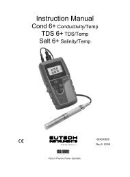
5.2.6 Transferring stored data to a PC using an USB/ irDA Dongle.<br />
You can purchase an USB/ irDA dongle<br />
01X447602 (see accessories page at the back<br />
of this manual) and transfer data from your<br />
meter using the USB port.<br />
Please note: This accessory is specially<br />
engineered to match your meter’s software to<br />
the application in your laptop or PC. If you<br />
purchase this item from a different source, it<br />
will NOT be compatible for transferring the<br />
data.<br />
28
6. Technical Specifications<br />
Temperature (pH and Conductivity)<br />
Range<br />
-10.0 ºC to 110.0 ºC (14.0 ºF to 230.0 ºF)<br />
Resolution 0.1 ºC/ 0.1 ºF<br />
Relative Accuracy ± 0.5 ºC / ± 0.9 ºF<br />
Temp. Input Connector<br />
8-pin Round<br />
Temperature (DO)<br />
Range<br />
-10.0 ºC to 60.0 ºC (14.0 ºF to 140.0 ºF)<br />
Resolution 0.1 ºC/ 0.1 ºF<br />
Relative Accuracy ± 0.5 ºC / ± 0.9 ºF<br />
Model<br />
pH pH <strong>600</strong> pH 610 pH 620, PD 650,PCD 650<br />
Range -2.00 to 20.0 pH -2.000 to 20.000 pH<br />
Resolution 0.1/ 0.01 pH 0.1/0.01/0.001 pH<br />
Relative Accuracy ± 0.01 pH + 1 LSD ± 0.002 pH + 1 LSD<br />
No. of Calibration points<br />
1 (offset) to 6 points<br />
No. of Buffer Options 15<br />
Calibration due alarm<br />
User configurable (up to 30 days)<br />
Set point alarm<br />
User configurable<br />
Auto buffer recognition<br />
Yes<br />
pH buffer Groups & Calibration<br />
Points<br />
Calibration<br />
Window<br />
USA<br />
NIST<br />
DIN<br />
USA : 1.68, 4.01, 7.00, 10.01, 12.45<br />
NIST: 1.68, 4.01, 6.86, 9.18, 12.45<br />
DIN : 1.09, 3.06, 4.65, 6.79, 9.23, 12.74<br />
PWB : 4.10, 6.97<br />
± 1.5 pH (for 7.00pH), ±1 pH (for all other buffers)<br />
± 1.35 pH (for 6.86pH), ±1 pH (for all other buffers)<br />
± 0.8 pH (for 1.09, 3.06, 4.65pH), ±1 pH (for 9.23, 12.74pH),<br />
±1.34 pH (for 6.79pH)<br />
± 0.8 pH<br />
PWB<br />
Custom buffer calibration Yes (2 to 5)<br />
Slope/Offset display<br />
Yes (Display + Icon)<br />
mV<br />
Range<br />
± 2000.0mV<br />
Resolution<br />
0.1 mV<br />
Relative Accuracy<br />
± 0.2 mV + 1 LSD<br />
Ion<br />
Range 0.001 to 19900<br />
Units<br />
ppm, molar, mg/L<br />
Resolution<br />
2 or 3 digits<br />
Relative Accuracy<br />
0.5% FS (monovalent) 1% FS (divalent)<br />
29
Conductivity<br />
Range Measuring ranges Resolution<br />
1<br />
0.050uS to 2.000uS<br />
0.01uS*<br />
Sub range<br />
Accuracy<br />
1% of FS<br />
Cal Standards<br />
No<br />
2<br />
2.000uS to 9.990 uS<br />
10.00uS to 99.99uS<br />
100.0uS to 300.0uS<br />
0.01uS*<br />
0.01uS<br />
0.1uS<br />
1% of FS<br />
1% of FS<br />
1% of FS<br />
84.00uS<br />
3<br />
300.0uS to 999.9uS<br />
1.000mS to 4.000mS<br />
0.1uS<br />
0.001mS<br />
1% of FS<br />
1% of FS<br />
1.413mS<br />
4<br />
4.000mS to 9.999mS<br />
10.00mS to 40.00mS<br />
0.001mS<br />
0.01mS<br />
1% of FS<br />
1% of FS<br />
12.88mS<br />
5<br />
40.00mS to 99.99mS<br />
100.0mS to 500.0mS<br />
0.01mS<br />
0.1mS<br />
1% of FS<br />
1% of FS<br />
111.8mS<br />
* Display resolution is 0.001 but actual<br />
resolution shows 0.01.<br />
TDS<br />
Range Measuring ranges Resolution Sub range Accuracy<br />
1<br />
0.050ppm to 2.000ppm<br />
0.01ppm*<br />
1% of FS<br />
2<br />
2.000ppm to 9.990 ppm<br />
10.00ppm to 99.99ppm<br />
100.0ppm to 300.0ppm<br />
0.01ppm*<br />
0.01ppm<br />
0.1ppm<br />
1% of FS<br />
1% of FS<br />
1% of FS<br />
3<br />
300.0ppm to 999.9ppm<br />
1.000ppt to 4.000ppt<br />
0.1ppm<br />
0.001ppt<br />
1% of FS<br />
1% of FS<br />
4<br />
4.000ppt to 9.999ppt<br />
10.00ppt to 40.00ppt<br />
0.001ppt<br />
0.01ppt<br />
1% of FS<br />
1% of FS<br />
5<br />
40.00ppt to 99.99ppt<br />
100.0ppt to 500.0ppt<br />
0.01ppt<br />
0.1ppt<br />
1% of FS<br />
1% of FS<br />
* Display resolution is 0.001 but actual<br />
resolution shows 0.01.<br />
Salinity<br />
Range Measuring ranges Resolution Sub range Accuracy<br />
1<br />
0.020ppm to 0.770ppm<br />
0.01ppm*<br />
1% of FS<br />
2<br />
0.770ppm to 9.990 ppm<br />
10.00ppm to 99.99ppm<br />
100.0ppm to 143.3ppm<br />
0.01ppm*<br />
0.01ppm<br />
0.1ppm<br />
1% of FS<br />
1% of FS<br />
1% of FS<br />
3<br />
143.3ppm to 999.9ppm<br />
1.000ppm to 2.138ppt<br />
0.1ppm<br />
0.001ppt<br />
1% of FS<br />
1% of FS<br />
4<br />
2.138ppt to 9.999ppt<br />
10.00ppt to 23.64ppt<br />
0.001ppt<br />
0.01ppt<br />
1% of FS<br />
1% of FS<br />
5<br />
23.64ppt to 80.00ppt<br />
0.01ppt<br />
1% of FS<br />
* Display resolution is 0.001 but actual<br />
resolution shows 0.01.<br />
30
Resistivity<br />
Range Measuring ranges Resolution Sub range Accuracy<br />
5<br />
10.00MΩ to 20.00MΩ<br />
1.000MΩ to 9.999MΩ<br />
500.0KΩ to 999.9KΩ<br />
0.01MΩ<br />
0.001MΩ<br />
0.1KΩ<br />
1% of FS<br />
1% of FS<br />
1% of FS<br />
4<br />
100.0KΩ to 500.0KΩ<br />
10.00KΩ to 99.99KΩ<br />
3.333KΩ to 9.999KΩ<br />
0.1Ω<br />
0.01Ω<br />
0.001Ω<br />
1% of FS<br />
1% of FS<br />
1% of FS<br />
3<br />
1.000KΩ to 3.333KΩ<br />
250.0Ω to 999.9Ω<br />
0.001Ω<br />
0.1Ω<br />
1% of FS<br />
1% of FS<br />
2<br />
100.0Ω to 250.0Ω<br />
25.00Ω to 99.99Ω<br />
0.1Ω<br />
0.01Ω<br />
1% of FS<br />
1% of FS<br />
1<br />
10.00Ω to 25.00Ω<br />
2.000Ω to 9.990Ω<br />
0.01Ω<br />
0.01Ω*<br />
1% of FS<br />
1% of FS<br />
Conductivity / TDS / Salinity /<br />
Resistivity<br />
* Display resolution is 0.001 but actual<br />
resolution shows 0.01.<br />
COND <strong>600</strong> COND 610<br />
Conductivity Range 0 to 200mS 0 to 500 mS<br />
Salinity - 80 ppt<br />
Resistivity - 0 to 20.00MΩ<br />
TDS 200 ppt (depending on TDS factor) 500 ppt (depending on TDS factor)<br />
Conductivity Cell constant 0.010 to 10.000<br />
Conductivity Cell<br />
2 & 4 Cell<br />
TDS Conversion Factor 0.400 to 1.000<br />
Temperature Comp. Linear Linear & Pure<br />
Cal-Auto/<strong>Manual</strong><br />
Cal-Single/Multi<br />
Cal Due Alarm<br />
Set Point Alarm<br />
Input Conductivity<br />
Yes<br />
Yes<br />
Yes (max-30 days)<br />
Yes<br />
8 Pin Round<br />
Dissolved Oxygen DO <strong>600</strong>, PD 650, CD 650, PCD 650<br />
DO Range<br />
Resolution<br />
Accuracy<br />
Dissolved Oxygen Probe<br />
Mode<br />
Temperature Comp.<br />
Barometric Pressure Compensation<br />
Barometric Pressure Range<br />
Barometric Pressure Resolution<br />
0 to <strong>600</strong> %/ 90 mg/l<br />
0.1%, 0.01 mg/L<br />
± 2%, ± 0.2 mg/L<br />
Galvanic<br />
% Sat, mg/L, ppm<br />
Linear<br />
Automatic<br />
450 to 825 mmHg<br />
1 mmHg<br />
Barometric Pressure Accuracy ± 1%<br />
Salinity Correction<br />
Cal Due Alarm<br />
0 to 50 ppt<br />
Yes (max -30 days)<br />
31
Set Point Alarm<br />
Input DO<br />
Display<br />
Yes<br />
6 Pin Round<br />
Display type<br />
Dot matrix LCD with backlighting<br />
Screen resolution 110 x 128<br />
Viewing area<br />
68 x 74 mm<br />
Backlit<br />
Yes<br />
Other<br />
Data logging<br />
500 data sets<br />
Data communication<br />
IrDA / RS232C-Infrared<br />
Auto Data logging<br />
Yes<br />
GLP (Good Lab Practice)<br />
Yes<br />
Ingress protection IP 67<br />
Dimensions<br />
95mm (W) x 185mm (L) x 58.5mm (H) - Without Rubber Boot<br />
101mm (W) x 191mm (L) x 61mm (H) - With Rubber Boot<br />
Weight<br />
380g (Without Rubber Boot)<br />
Power Input pH <strong>600</strong> / 610 / 620 All other models<br />
Battery<br />
4 x Alkaline AA size, 1.5 V<br />
Battery Life<br />
500 Hrs (without backlight & serial data 200 Hrs (without backlight & serial data<br />
transfer)<br />
transfer)<br />
Power adapter<br />
Input: 100-240V AC<br />
Output: DC 9-12V, 6W Max<br />
32
7. Accessories<br />
<strong>Eutech</strong> Instruments<br />
Product Description<br />
<strong>Eutech</strong> Instruments Order Code<br />
8 pin connector Temperature probe (3m Cable) ECPHWPTEM03J<br />
8 pin connector Temperature probe (1m Cable) ECPHWPTEM01J<br />
General Purpose Plastic-Body, Double Junction, Ag/AgCl pH<br />
electrode (3m Cable)<br />
ECFC7252203B<br />
General Purpose Plastic-Body, Double Junction, Ag/AgCl pH<br />
electrode (1m Cable)<br />
General Purpose Plastic-Body, 3-in-1,pH/Temp Ag/AgCl pH electrode<br />
(1m Cable)<br />
2 Stainless Steel Rings Ultem-body Electrode with ATC (3m cable<br />
length)<br />
4-cell, Graphite, Epoxy-body Electrode with ATC (3m cable length)<br />
Galvanic Dissolved Oxygen probe with ATC (3m cable length)<br />
Membrane & O-ring (pack of 5)<br />
Assembled Membrane Cap Housing<br />
ECFC7252201B<br />
ECFC7352901J<br />
ECCONSEN9103J<br />
ECCONSEN9203J<br />
ECDOHANDYNEW<br />
01X241603<br />
15X241402<br />
Membrane removal tool<br />
Electrode Guard Removal Tool<br />
DO Refilling electrolyte, 60 mL<br />
Rubber Boot for <strong>600</strong> series meters<br />
100-240VAC Power Adapter<br />
USB/ irDA Converter<br />
15X241502<br />
15X241504<br />
01X211226<br />
ECRUBBERBT<strong>600</strong><br />
01X030132<br />
01X447602<br />
Oakton Instruments<br />
Product Description<br />
Oakton Instruments Order Code<br />
8 pin connector Temperature probe (3m Cable) 35418-07<br />
8 pin connector Temperature probe (1m Cable) 35418-05<br />
General Purpose Plastic-Body, Double Junction, Ag/AgCl pH<br />
electrode (OKFC7252203B, 3m Cable)<br />
35816-77<br />
General Purpose Plastic-Body, Double Junction, Ag/AgCl pH<br />
electrode (1m Cable)<br />
General Purpose Plastic-Body, 3-in-1,pH/Temp Ag/AgCl pH electrode<br />
(1m Cable)<br />
2-cell Electrode with ATC, cell constant K=1.0 (OKCONSEN9103J,<br />
3m cable)<br />
35641-51<br />
35816-71<br />
35408-57<br />
2-cell Electrode with ATC, cell constant K=1.0 35408-52<br />
4-cell Electrode with ATC, cell constant K=0.3 35408-56<br />
33
2-cell Electrode with ATC, cell constant K=10.0 35408-54<br />
2-cell Electrode with ATC, cell constant K=0.1 35408-50<br />
Galvanic Dissolved Oxygen probe with ATC with 10-ft cable 35640-50<br />
Galvanic Dissolved Oxygen probe with ATC 25-ft cable 35640-52<br />
Galvanic Dissolved Oxygen probe with ATC 50-ft cable 35640-54<br />
Galvanic Dissolved Oxygen probe with ATC 100-ft cable 35640-56<br />
Replacement batteries, AA. Pack of 4 09376-01<br />
Replacement DO membranes, Pack of 5. 35640-74<br />
Replacement DO membranes, Pack of 25. 35640-75<br />
Replacement membrane kit; two membrane caps and one bottle of<br />
electrolyte solution<br />
35640-80<br />
Assembled Membrane Cap Housing 35640-72<br />
Membrane removal tool 35640-79<br />
Zero oxygen solution, 500 mL 00653-00<br />
DO Refilling electrolyte , 500 mL 35640-71<br />
Electrolyte DO powder (58.5 g) 35640-70<br />
Rubber Boot for <strong>600</strong> series meters 35418-86<br />
100-220VAC Power Adapter 35418-83<br />
Carrying Case with 4 sets of empty 60 ml bottle 35632-99<br />
8. Warranty & Return Policy<br />
8.1 Warranty<br />
<strong>Eutech</strong> Instruments supplies this meter with a 3-year warranty and 6-month<br />
warranty for electrode against manufacturing defects from the date of purchase.<br />
If repair or adjustment is necessary and has not been the result of abuse or<br />
misuse within the designated period, please return – freight pre-paid – and<br />
correction will be made without charge. <strong>Eutech</strong> Instruments/ Oakton<br />
Instruments will determine if the product problem is due to deviations or<br />
customer misuse.<br />
Out of warranty products will be repaired on a charged basis.<br />
Exclusions<br />
The warranty on your instrument shall not apply to defects resulting from:<br />
• Improper or inadequate maintenance by customer<br />
• Unauthorized modification or misuse<br />
• Operation outside of the environment specifications of the products<br />
8.2 Return of Goods<br />
Before returning goods for any reason whatsoever, the Customer Service Dept.<br />
has to be informed in advance. Items must be carefully packed to prevent<br />
34
damage during shipment, and insured against possible damage or loss. <strong>Eutech</strong><br />
Instruments/ Oakton Instruments will not be responsible for any damage<br />
resulting from careless or insufficient packing.<br />
Warning: Shipping damage as a result of inadequate packaging is the<br />
user's/distributor’s responsibility. Please follow the guidelines below before<br />
shipment.<br />
8.3 Guidelines for Returning Unit for Repair<br />
Use the original packaging material if possible when shipping the unit for repair.<br />
Otherwise wrap it with bubble pack and use a corrugated box for additional<br />
protection. Include a brief description of any faults suspected for the<br />
convenience of Customer Service Dept., if possible.<br />
- END OF GENERAL GUIDE SECTION -<br />
35
TEMPERATURE<br />
PARAMETER GUIDE<br />
i. Temperature Setup Mode<br />
ii. Temperature Calibration – ATC and MTC Mode<br />
iii. Temperature Measurement Mode<br />
FOR ALL MODELS :<br />
pH <strong>600</strong>/ 610/ 620 COND <strong>600</strong>/610<br />
DO <strong>600</strong> PC 650<br />
PD 650 CD 650<br />
PCD 650<br />
36
1. Temperature Setup<br />
Temperature setup sub-group allows you to configure temperature measurement &<br />
calibration related settings of the meter.<br />
Temperature Setting Page<br />
Figure 13 : Temperature Settings Page<br />
Parameter Description Factory Default<br />
Unit<br />
Sets the unit of measurement for temperature.<br />
ºC<br />
Available units: ºC and ºF<br />
Mode Sets the temperature compensation mode.<br />
ATC – Automatic Temperature Compensation<br />
MTC – <strong>Manual</strong> Temperature Compensation<br />
ATC<br />
Press (Up) or (Down) arrow key to change unit of measurement and<br />
temperature compensation mode.<br />
2. Temperature Calibration<br />
2.1 About Temperature Calibration<br />
It is important to ensure that temperature calibration is carried out prior to pH,<br />
conductivity and DO calibration since temperature readings affect the accuracy<br />
of pH, conductivity and DO measurements. You need to perform temperature<br />
calibration only if the temperature value displayed on the meter is different from<br />
that of a calibrated thermometer or if cell constant setting is changed. A<br />
temperature offset calibration of ± 5 °C/± 9 °F from the default reading is<br />
allowed for ATC mode.<br />
The built-in temperature sensor of conductivity and DO probes are factory<br />
calibrated. The built-in ATC probe of the conductivity cells can be used for<br />
temperature readout and compensation of the pH values. DO in mg/L is<br />
dependent on temperature, so it is first necessary to calibrate or verify the<br />
temperature reading. Calibrate the probes only if you suspect temperature<br />
errors may have occurred over a long period of time or if you have a<br />
38
eplacement probe. This procedure offers offset adjustment of the probe to<br />
ensure more accurate temperature measurement.<br />
Use a thermometer you are certain is accurate to measure the temperature of<br />
your sample.<br />
2.2 Temperature Calibration for ATC mode<br />
Make sure you have selected ‘ATC’ and the required unit of measurement (ºC<br />
or ºF) in Temperature settings. Switch the meter on. Make sure the meter is in<br />
measurement mode.<br />
1. Press CAL (F2) to go to calibration mode.<br />
Note: If the meter is password protected, you will be prompted to enter a<br />
password. Refer to page 19- Accessing Calibration mode when<br />
password protection enabled.<br />
2. The meter shows ‘Calibration-Rinse Electrode’ screen for few seconds and<br />
then shows the cell constant adjustment screen.<br />
3. Press NEXT (F3) key. (For conductivity mode only. In pH mode, pressing<br />
this key will take you to the Report page)<br />
4. Press TEMP (F1) to go to temperature calibration. The temperature<br />
calibration screen appears.<br />
Figure 14 : Temperature Calibration Screen<br />
1. The screen shows two readings. The upper display shows the temperature<br />
reading of the solution with respect to previous calibration (if any) & lower<br />
displays shows the temperature reading of the solution without any<br />
calibration (default reading). Use & keys to adjust the upper display to<br />
the temperature reading of the thermometer.<br />
Note: The meter allows you to adjust the upper display reading up to ±5<br />
ºC or ±9 ºF. (Calibration window)<br />
2. Press ENTER key to confirm temperature value.<br />
39
2.3 Temperature Calibration for MTC mode<br />
Make sure you have selected ‘MTC’ and required unit of measurement (ºC or<br />
ºF) in Temperature settings. Switch on the meter. Make sure the meter is in<br />
measurement mode.<br />
1. Press CAL (F2) to go to calibration mode.<br />
2. The meter shows the ‘Calibration-Rinse Electrode’ screen for a few seconds<br />
and then shows the cell constant adjustment screen.<br />
3. Press NEXT (F3) key. (For conductivity mode only. In pH mode, pressing<br />
this key will take you to the Report page)<br />
4. Press TEMP (F1) to go to temperature calibration. The temperature<br />
calibration screen appears.<br />
5. The screen shows two readings. The upper display shows the temperature<br />
reading of the solution with respect to previous calibration (if any) & lower<br />
displays shows the temperature reading of the solution without any<br />
calibration (default reading). Use & keys to adjust the upper display to<br />
the temperature reading of the thermometer.<br />
Note: The meter allows you to adjust the upper display reading to any<br />
value within the measuring range -10.0 ºC to 110.0 ºC (14.0 ºF to 230.0 ºF).<br />
6. Press ENTER key to confirm temperature value.<br />
Function Keys available in temperature calibration screen:<br />
NEXT (F3) Goes to measurement mode from where you entered calibration<br />
ESC (F4) Goes to measurement mode from where you entered calibration<br />
ENTER Confirms calibration<br />
Increase/decrease temperature reading<br />
(Not functional)<br />
3. Temperature Measurement<br />
There is no page in the meter dedicated to temperature measurement mode as the<br />
temperature is displayed with all other main parameters.<br />
- END OF TEMPERATURE SECTION -<br />
40
pH<br />
PARAMETER GUIDE<br />
1. pH Setup Mode<br />
2. pH Calibration Mode<br />
3. pH Measurement Mode<br />
FOR MODELS :<br />
pH <strong>600</strong>/ 610/ 620<br />
PC 650<br />
PD 650<br />
PCD 650<br />
42
1. pH Setup<br />
pH setup sub-group allows you to configure pH measurement & calibration related<br />
settings of the meter. The settings are displayed in 2 pages. Press NEXT-P (F2) and<br />
PREV-P (F1) to navigate through these pages.<br />
pH Settings Page 1 – pH Measurement & Calibration<br />
Figure 15: pH Settings Page 1 – pH Measurement & Calibration<br />
This page allows you to set pH measurement & calibration related settings of the<br />
meter.<br />
Parameter Description Factory Default<br />
Buffer Select your preferred pH standard buffer group for<br />
USA<br />
calibration & auto-recognition.<br />
Available groups: USA, NIST, DIN, PWB & USER<br />
Select ‘USER’ if you need to use a custom buffer for<br />
calibration.<br />
Cal points Select the number of calibration points you intend to<br />
3<br />
calibrate the meter using the selected buffer group.<br />
Available points: depends on the selected buffer group<br />
Alarm Set ENABLE – The measurement screen shows HI or LO<br />
DISABLE<br />
Point alarm indicators when the meter reading is above ‘HI<br />
alarm value’ or below ‘LO alarm value’ specified in HI<br />
pH & LO pH parameters (below)<br />
DISABLE – HI and LO alarms are not shown in the<br />
LCD<br />
Hi pH Specify Hi alarm value here. The Hi alarm occurs<br />
20.00pH<br />
when the pH reading goes above this value<br />
Available range: Hi pH (specified below) to 20.00<br />
(This parameter is not editable when ‘ALARM SET<br />
POINT’ is disabled)<br />
Lo pH Specify Lo alarm value here. The Lo alarm occurs<br />
when the pH reading goes below this value<br />
Available range: 0.00 to Lo pH (specified above)<br />
(This parameter is not editable when ‘ALARM SET<br />
POINT’ is disabled)<br />
0.00pH<br />
44
pH Settings Page 2 – Calibration Due Alarm & pH Resolution<br />
Figure 16: pH Settings Page 2 – Cal-due Alarm & pH Resolution<br />
Parameter Description Factory Default<br />
pH Calibration Due Specify number of days for the pH calibration<br />
alarm. The meter shows CAL DUE indicator after<br />
calibration due days are passed from the last<br />
calibration date.<br />
Available range: 0 to 30<br />
5 Days<br />
pH Resolution<br />
Sets the resolution for pH measurement<br />
Available range: 0.1, 0.01, 0.001<br />
Press (Up) or (Down) arrow key to change pH measurement & calibration<br />
related settings of the meter.<br />
0.00<br />
2. pH Calibration<br />
2.1 About pH Calibration<br />
When you re-calibrate your meter, previous pH calibration points are replaced<br />
on a point by point basis. For example, if you previously calibrated your meter<br />
at pH 4.01, 7.00, and 10.01, and you have now re-calibrated at pH 7.00, the<br />
meter retains the old calibration data at pH 4.01 and pH 10.01. The meter<br />
shows previously calibrated points in the display when the meter is in pH<br />
measurement mode. To completely re-calibrate the meter, or when you use a<br />
replacement probe, it is best to clear the previous calibration and re-calibrate<br />
the meter at all points.<br />
The meter supports four internationally recognized standard buffer groups:<br />
USA, NIST, DIN & PWB. The default buffer group is USA.<br />
The meter is capable of calibrating up to 6 points, depending on the standard<br />
buffer selected. When completely re-calibrating the meter, the first point of<br />
calibration should be one of the following, depending on your choice of standard<br />
buffer group.<br />
45
Buffer<br />
First Point of Calibration<br />
Other Available Calibration Points<br />
Group (when complete re-calibration)<br />
USA pH 7.00 pH 1.68, 4.01, 10.01, and 12.45<br />
NIST pH 6.86 pH 4.01, 6.86, 9.18, and 12.45<br />
DIN pH 6.79 pH 1.09, 3.06, 4.65, 9.23, and 12.75<br />
PWB pH 6.97 pH 4.10<br />
Table 1: Buffer Groups and Calibration Points<br />
The meter automatically recognizes and calibrates to these standard pH buffer<br />
values, which makes pH calibration faster and easier.<br />
2.2 pH buffer group for calibration and auto-recognition<br />
This option allows you to choose a buffer group from four internationally<br />
recognized standard buffer groups namely USA, NIST, DIN & PWB. The default<br />
buffer group is USA. Refer to the ‘pH Setup’ section (pH Parameter guide) for<br />
information on how to set the meter to a particular buffer group.<br />
2.2.1 pH Calibration points<br />
This option allows you to calibrate up to 6 points, depending on the standard<br />
buffer selected. Or you can choose to have custom buffers with 2 to 5 points.<br />
When completely re-calibrating the meter, the first point of calibration should be<br />
one of the following, depending on your choice of standard buffer group. The<br />
meter automatically recognizes and calibrates to the standard pH buffer values,<br />
which makes pH calibration faster and easier.<br />
2.3 pH Calibration with a Standard Buffer<br />
Make sure you have selected a standard buffer with which you intend to<br />
perform pH calibration.<br />
2.3.1 To start pH Calibration:<br />
1. Switch the meter on and make sure the meter is in pH measurement mode.<br />
2. Press CAL (F2) to start calibration.<br />
Note: If the meter is password protected, you will be prompted to enter a<br />
password. Refer 3.4.1 on page 19.<br />
3. The meter shows the ‘Calibration-Rinse Electrode’ screen for a few seconds<br />
and then shows the pH calibration screen.<br />
46
(a)<br />
(b)<br />
Figure 17: pH Calibration Screens<br />
4. Rinse the electrode in clean water and prepare electrode for calibration.<br />
Note: If you wish to completely re-calibrate the meter, you need to clear<br />
previous calibration data. Press CLR-C (F2) key to clear previous<br />
calibration. The meter shows your confirmation screen. Press ENTER<br />
key to confirm deleting previous calibration. Once cleared, you need to<br />
calibrate the first point that corresponds to your selected buffer group.<br />
5. Dip the probe in calibration buffer. The tip of the probe must be completely<br />
immersed into the solution. Stir the probe gently to create a homogeneous<br />
solution.<br />
6. The display shows the pH reading. The meter scans through all the<br />
available (un-calibrated) points for the selected buffer group until it finds a<br />
close match within its acceptable calibration window. Once a match is<br />
found, the display shows the ‘Stable’ indicator.<br />
7. Press ENTER key to confirm the calibration.<br />
8. Rinse the probe with clean water.<br />
9. Place it in the next buffer and follow steps 5 and 7 to calibrate other points.<br />
Function Keys available in pH Calibration mode:<br />
TEMP (F1) Goes to temperature calibration<br />
CLR-C (F2) Clears previous calibration (if any) after ENTER key is pressed in<br />
confirmation screen<br />
NEXT (F3) Shows calibration report<br />
ESC (F4) Exits from calibration and goes back to pH measurement mode<br />
ENTER Confirms the calibration<br />
(Not functional)<br />
47
2.4 pH Calibration with a User-defined Buffer<br />
If you selected ‘USER’ (Custom) buffer in the pH Setup, the following screen is<br />
shown when you enter calibration mode. You need to prepare at least 2 custom<br />
buffers of known pH values.<br />
Note: Custom buffer solution values should be at least 1 pH unit apart<br />
from each other. Otherwise, the meter will not accept the buffer values.<br />
Figure 18 : User-define Buffer Screen<br />
1. Rinse the electrode in clean water and prepare electrode for calibration.<br />
Note: If you wish to completely re-calibrate the meter, you need to clear<br />
previous calibration data. Press CLR-C (F2) key to clear previous<br />
calibration. The meter shows you confirmation screen. Press ENTER key<br />
to confirm deleting previous calibration.<br />
2. Dip the probe in custom calibration buffer. The tip of the probe must be<br />
completely immersed into the solution. Stir the probe gently to create a<br />
homogeneous solution.<br />
3. The screen shows 2 readings. The upper display shows the pH reading of<br />
the solution with respect to previous calibration (if any) & lower display<br />
shows the pH reading of the solution without any calibration. Use &<br />
keys to adjust the upper display to the pH value of your custom buffer.<br />
4. Press ENTER key to confirm the calibration.<br />
5. Rinse the probe with clean water. Place it in the next buffer and follow steps<br />
2, 3 and 4 to calibrate other points.<br />
Function Keys available in pH Calibration mode:<br />
TEMP (F1) Goes to temperature calibration<br />
CLR-C (F2)<br />
Clears previous calibration (if any) after ENTER key is pressed for the<br />
confirmation screen<br />
NEXT (F3) Shows calibration report<br />
48
ESC (F4)<br />
ENTER<br />
Exits from calibration and goes back to pH measurement mode<br />
Confirms the calibration<br />
Increases/decreases pH buffer reading<br />
(Not functional)<br />
2.5 Calibration Report<br />
Calibration report gives you detailed information on calibration. It includes date<br />
& time, buffer group, offset, temperature, number of days calibration is over due<br />
and slope information.<br />
2.5.1 To View Calibration Report:<br />
1. From pH measurement mode, press left or right arrow key to navigate<br />
to other available functions until you see REPO function in the LCD.<br />
2. Press REPO (F2) key. The first page of calibration report is shown in the<br />
display.<br />
3. Press PAGE (F1) to view the second page of the report.<br />
4. Press PRIN (F2) to transfer the calibration report to computer through IrDA.<br />
Figure 19: pH Calibration Report<br />
Example: In the given pH calibration report, 4-point calibration has been done<br />
for USA buffer group (pH 1.68, pH 4.01, pH 7.00 & pH 12.45).<br />
• The slope is 93 for the range enveloped from pH 1.68 to pH 4.01.<br />
• The slope is 88 for the range enveloped from pH 4.01 to pH 7.00.<br />
• The slope is 94 for the range enveloped from pH 7.00 to pH 12.45 where<br />
pH 10.01 calibration point has been skipped.<br />
Function Keys available in pH calibration report screen:<br />
PAGE (F1) Goes to the second page of the calibration report<br />
BACK (F1) Goes to the first page of the calibration report<br />
PRIN (F2) Transfers calibration report to Computer through IrDA<br />
49
NEXT (F3)<br />
ESC (F4)<br />
ENTER<br />
Goes to pH measurement mode<br />
Goes to pH measurement mode<br />
(Not functional)<br />
(Not functional)<br />
2.6 Average Slope Indicator of pH Probe<br />
Each time you perform pH calibration; the meter calculates the average slope of<br />
your probe and graphically indicates it in the header section of the LCD screen.<br />
Figure 20 : Average Slope Indicator<br />
Number of bars in the indicator shows the slope value:<br />
Number of Bars Average Slope of the pH Probe<br />
4 Above 90%<br />
3 90% to 80%<br />
2 80% to 70%<br />
1 Below 70%<br />
3. pH Measurement Mode<br />
3.1 Resolution of pH Reading<br />
By default, the resolution is set to 0.00. You can change the resolution in the<br />
setup mode. pH resolution can be adjusted from 0.0 to 0.000 pH.<br />
50
3.2 Indicators in pH measurement screen<br />
In pH measurement mode, the meter displays pH and temperature reading.<br />
2<br />
1<br />
4<br />
3<br />
5<br />
6<br />
8<br />
10<br />
7<br />
9<br />
11<br />
12<br />
Item Description<br />
1 Measurement mode indicator<br />
2 Appears when the reading is stable<br />
3 Appears when the reading is on hold<br />
4 pH reading<br />
5 Units of measurement<br />
6 Temperature reading & units<br />
7 Temperature compensation mode<br />
8 pH HI & LO Alarm limits<br />
9 pH Alarm indicator<br />
10 Calibration Due indicator<br />
11 Response time of the pH probe<br />
12 Calibrated Points<br />
- END OF pH SECTION -<br />
51
mV<br />
PARAMETER GUIDE<br />
1. mV Setup Mode<br />
2. mV Calibration Mode<br />
3. mV Measurement Mode<br />
FOR MODELS :<br />
pH <strong>600</strong>/ 610/ 620<br />
PC 650<br />
PD 650<br />
PCD 650<br />
52
1. mV Setup Mode<br />
There is no setup mode for mV parameter.<br />
2. mV Calibration Mode<br />
2.1 mV Calibration with a Standard ORP Calibration Solution<br />
Use a standard ORP solution of known value for calibration. You need to<br />
calibrate only 1-point.<br />
1. Switch the meter on. Make sure the meter is in mV measurement mode.<br />
2. Press CAL (F2) to go to calibration mode.<br />
Note: If the meter is password protected, you will be prompted to enter a<br />
password.<br />
3. The meter shows the ‘Calibration-Rinse Electrode’ screen for a few seconds<br />
and then shows the mV calibration screen.<br />
Figure 21 : mV Calibration Screen & Calibration Report<br />
4. The screen shows two readings. The upper display shows the mV reading<br />
of the solution with respect to previous calibration (if any) & lower displays<br />
shows the absolute mV reading of the solution without any calibration<br />
(default reading). Use & keys to adjust the upper display to the mV<br />
value of the solution.<br />
Note: The meter allows you to adjust the upper display reading up to<br />
±150 mV with respect to the default reading.<br />
5. Press ENTER key to confirm the entered value.<br />
6. The calibration is completed. The meter shows the calibration report.<br />
54
7. Press ESC (F4) to go to measurement mode. The meter shows the relative<br />
mV reading of the solution in measurement mode, if offset is not zero.<br />
Note: The function of the keys available on the mV calibration/ report<br />
screen is same as previously described in pH calibration with a userdefined<br />
buffer section.<br />
2.2 Calibration Report<br />
Calibration report gives you information on calibration. It includes date & time on<br />
which the last calibration was done and the offset.<br />
2.2.1 To View Calibration Report:<br />
1. From mV measurement mode, press left or right arrow key to navigate<br />
to other available functions until you see REPO function in the LCD<br />
2. Press REPO (F2) key. The calibration report is shown in the display.<br />
3. Press PRIN (F2) to transfer the calibration report to the computer.<br />
3. mV Measurement Mode<br />
In mV measurement mode, the meter displays mV and temperature reading.<br />
Depending on application, you can connect a suitable ORP probe to the meter or use<br />
the pH probe.<br />
3.1 Indicators in mV measurement mode<br />
2<br />
1<br />
3<br />
4<br />
5<br />
6<br />
7<br />
Figure 22 : mV Measurement Screen<br />
55
Item Description<br />
1 Measurement mode indicator<br />
2 Appears when the reading is stable<br />
3 Appears when the reading is on hold<br />
4 mV reading<br />
5 Units of measurement<br />
6 Temperature reading & units<br />
7 Temperature compensation mode<br />
Note: If offset is not zero, the meter displays relative mV reading of the<br />
solution in measurement mode.<br />
- END OF mV SECTION -<br />
56
ION<br />
PARAMETER GUIDE<br />
1. Ion Setup Mode<br />
2. Ion Calibration Mode<br />
3. Ion Measurement Mode<br />
FOR MODELS :<br />
pH 620<br />
PC 650<br />
PD 650<br />
PCD 650<br />
58
1. Ion Setup<br />
Ion setup sub-group allows you to configure Ion measurement & calibration related<br />
settings of the meter.<br />
Ion Settings Page<br />
Figure 23: Ion Settings Page<br />
Parameter Description Factory Default<br />
Ion unit<br />
Sets the unit of measurement for Ion.<br />
Available units: ppm, molar and mg/L<br />
ppm<br />
Press (Up) or (Down) arrow key to change the value of a selected parameter.<br />
2. Ion Calibration Mode<br />
2.1 About Ion Calibration<br />
The meter supports Ion calibration up to 8 points with minimum of 2-points. The<br />
available 8-points are 0.001, 0.01, 0.1, 1, 10, 100, 1000 & 10000.<br />
The meter guides your through the calibration process with on-screen<br />
instructions and hints. If the second point and subsequent points are not within<br />
the allowable calibration window (15mV/decade to 90mV/decade), the meter will<br />
not accept the calibration.<br />
When you try to re-calibrate the meter with ISE, the meter gives you 2 options:<br />
• Clear the previous calibration (choose this if you wish to delete all<br />
previously calibrated points and re-calibrate with a new type of Ion)<br />
• Retain the previous calibration (choose this if you wish to retain<br />
previously calibrated points and re-calibrate new points or overwrite<br />
existing points with same type of Ion).<br />
60
Use standard solutions of 0.001, 0.01, 0.1, 1, 10, 100, 1000 & 10000 ppm for<br />
calibration. You need to calibrate minimum of 2-points. See “For Ion” under<br />
“Preparing the Meter for Calibration” on page 18.<br />
1. Switch on the meter. Make sure the meter is in Ion measurement mode.<br />
2. Press CAL (F2) to go to calibration mode.<br />
Note: If the meter is password protected, you will be prompted to enter<br />
a password.<br />
3. The meter shows the ‘Calibration-Rinse Electrode’ screen for a few<br />
seconds and then shows the Ion calibration screen.<br />
Figure 24 : Ion Calibration Screens<br />
Note: If there is an existing ion calibration in the meter, you will be given<br />
two options:<br />
• Clear the previous calibration (CLR-C) – choose this if you<br />
wish to delete all previously calibrated points and re-calibrate<br />
with a new type of ion.<br />
• Retain the previous calibration (NEXT) – choose this if you<br />
wish to retain previously calibrated points and re-calibrate new<br />
points (or overwrite existing points) with same type of ion.<br />
4. Dip the ISE in calibration solution. The tip of the probe must be completely<br />
immersed into the solution. Stir the probe gently to create a homogeneous<br />
solution.<br />
5. The calibration screen displays two readings. The upper display shows the<br />
lowest calibration point 0.001 ppm. The lower display shows the absolute<br />
mV reading of the solution without any calibration (default reading). Use<br />
& keys to select the required calibration point in the upper display.<br />
6. Allow time for the reading to stabilize. Press ENTER key to confirm the<br />
selected point. The meter flashes the upper display to acknowledge the first<br />
point calibration.<br />
61
7. The upper display shows the next calibration point.<br />
8. Rinse the ISE with clean water. Place it in the next calibration solution and<br />
follow the steps 4 through 6 to calibrate other points.<br />
Note: The meter accepts the second and subsequent points only if the mV<br />
readings are within the calibration window (15mV/decade to 90mV/decade).<br />
9. Press ESC (F4) to go to measurement mode.<br />
Note: The function of the keys available on the Ion calibration/ report<br />
screen is same as previously described in pH calibration with a userdefined<br />
buffer section.<br />
2.2 Calibration Report<br />
Calibration report gives you detailed information on calibration. It includes date<br />
& time, calibration points (Ion concentrations), absolute mV reading for each<br />
point and slope.<br />
Figure 25 : Ion Calibration Report<br />
Example: In the given Ion calibration report, calibration has been done for<br />
0.01, 0.1 & 10 Ion concentrations. The corresponding absolute mV readings<br />
are 0.0mV, 56.0mV & 156mV. The slope is 56 mV/decade for the range<br />
enveloped from 0.01 to 0.1 ppm. Similarly, the slope is 50 for the range<br />
enveloped from 0.1 to 10ppm where 0.1 calibration point has been skipped.<br />
2.2.1 To View Calibration Report<br />
1. From ION measurement mode, press left or right arrow key to<br />
navigate to other available functions until you see REPO function in the<br />
LCD<br />
2. Press REPO (F2) key. The calibration report is shown in the display.<br />
3. Press PRIN (F2) to transfer the calibration report to computer through IrDA.<br />
62
3. Ion Measurement Mode<br />
In Ion measurement mode, the meter displays Ion concentration (in ppm, molar or<br />
mg/L) and mV reading. Depending on application, you can connect a suitable Ion<br />
Selective Electrode (ISE) to the meter.<br />
3.1 Changing unit of measurement<br />
By default the measuring unit is ppm. You can select either molar or mg/L in the<br />
setup mode.<br />
3.2 Indicators in Ion measurement mode<br />
2<br />
Figure 26 : Ion measurement screen<br />
1<br />
3<br />
4<br />
5<br />
6<br />
Item Description<br />
1 Measurement mode indicator<br />
2 Appears when the reading is stable<br />
3 Appears when the reading is on hold<br />
4 Ion reading<br />
5 Units of measurement<br />
6 mV reading<br />
Note: If ion calibration has not been done, the display shows ‘- - - ’.<br />
- END OF ION SECTION -<br />
63
CONDUCTIVITY<br />
PARAMETER GUIDE<br />
1. COND Setup Mode<br />
2. COND Calibration Mode<br />
3. COND Measurement Mode<br />
FOR MODELS :<br />
COND <strong>600</strong>/610<br />
PC 650<br />
CD 650<br />
PCD 650<br />
64
1. Conductivity Setup<br />
Conductivity setup screen present many options to control the operating parameters,<br />
which can be controlled and set from the conductivity setup screen. The settings are<br />
displayed in 2 pages. Press NEXT-P (F2) and PREV-P (F1) to navigate through<br />
these pages.<br />
Conductivity Settings Page 1 – Operating Parameters<br />
Figure 27 : Conductivity Settings Page 1 – Operating Parameter<br />
This page allows you to set operating parameters for the conductivity measurement<br />
mode:<br />
Parameter Description Factory<br />
Default<br />
Pure water<br />
Coeff.<br />
Pure water coefficient will be calculated and applied automatically<br />
for ultra pure water measurement if enabled.<br />
ENABLE<br />
Lnr Temp<br />
Coefficient<br />
Normalization<br />
Temp<br />
Cell Constant<br />
Calibration<br />
due<br />
Calibration<br />
points<br />
Calibration<br />
mode<br />
Specify temperature coefficient to measure temperature<br />
corrected conductivity<br />
Select a default temperature that the meter will use along with the<br />
temperature coefficient to calculate a temperature corrected<br />
conductivity measurement.<br />
Select the appropriate cell constant of the conductivity cell.<br />
Available cell constants: 0.1 to 10<br />
Specify number of days for the Conductivity calibration alarm. The<br />
meter shows CAL DUE indicator after calibration date.<br />
Available range : 0 to 30 (if enabled)<br />
Single - In single point calibration one calibrated conductivity<br />
value can be used for the entire 5 conductivity ranges.<br />
Multi - In multi point calibration, you can calibrate one point in<br />
each of the measuring ranges (up to 5 points.)<br />
AUTO- In the automatic calibration mode, the meter automatically<br />
detects and verifies the appropriate known calibration standards<br />
solutions.<br />
<strong>Manual</strong>- In the manual calibration, you can manually input the<br />
appropriate values as your desired calibration standards in each<br />
specific range.<br />
2.100<br />
25<br />
1.000<br />
DISABLE<br />
Single<br />
Auto<br />
66
Note: 1. If pure water coefficient is set to ‘ENABLE’, the meter will apply pure<br />
water compensation automatically below 2 μS and switch back to linear<br />
compensation for above 2 µS.<br />
2. If pure water coefficient is set to ‘DISABLE’, Lnr Temp Coefficient applies<br />
throughout the measurement.<br />
Conductivity Settings Page 2 – Hi-Lo Set Points<br />
Figure 28 : Conductivity Settings Page 2 – Hi-Lo Alarm<br />
This page allows you to set alarm limits for the conductivity measurement mode.<br />
A visual alarm symbol will appear on the screen, if the conductivity value of the<br />
measurement is outside of the boundaries set by the minimum and maximum<br />
limits.<br />
Parameter Description Factory Default<br />
Alarm Set<br />
Points<br />
Hi ms<br />
Lo µs<br />
Set alarm limits for the conductivity measurement<br />
mode:<br />
ENABLE – The measurement screen shows HI or LO<br />
alarm indicators when the meter reading is above ‘HI<br />
alarm value’ or below ‘LO alarm value’ specified in HI<br />
& LO µS parameters (below)<br />
DISABLE – HI and LO alarms are not shown in the<br />
LCD<br />
Specify Hi alarm value here. The Hi alarm occurs<br />
when the conductivity reading goes above this value<br />
Available range: Hi µS (specified below) to 2.000 µS<br />
(This parameter is not editable when ‘ALARM SET<br />
POINT’ is disabled)<br />
Specify Lo alarm value here. The Lo alarm occurs<br />
when the conductivity reading goes below this value<br />
Available range:1.00 µS to Hi mS (specified above)<br />
(This parameter is not editable when ‘ALARM SET<br />
POINT’ is disabled)<br />
DISABLE<br />
2.000 µS<br />
1.000 µs<br />
67
2. Conductivity Calibration Mode<br />
2.1 Conductivity Calibration mode<br />
This option allows you to select automatic or manual calibration standard. In the<br />
automatic calibration mode, the meter automatically detects and verifies the<br />
appropriate known calibration standards solutions before accepting these<br />
particular calibration standards as one of its calibration values in a specific<br />
measurement range. Standard buffer values: 84.0 uS/ 1.413 mS/ 12.88 mS/<br />
111.8 mS<br />
In the manual calibration, non-standard calibration values can be used for<br />
calibration. You can manually input the appropriate values as your desired<br />
calibration standards in each specific range. The selected calibration standard<br />
will be displayed at the bottom of screen (See Figure 3 below).<br />
2.1.1 Conductivity calibration points<br />
This option allows you to select single or multi point calibration. Single point<br />
calibration refers to calibrating one conductivity value and uses it for the entire 5<br />
conductivity ranges. In multi point calibration, you can calibrate one point in<br />
each of the measuring ranges (up to 5 points). The selected calibration point will<br />
be displayed in the bottom of screen. For example: If single point calibration is<br />
selected it will display ‘SPC’ at the bottom of the screen, as shown in this<br />
diagram:<br />
Single point<br />
calibration<br />
Figure 29 : Calibration Standard & Point Indicator<br />
<strong>Manual</strong> calibration<br />
standard<br />
But if a multi-point calibration option (calibration for different ranges are<br />
indicated in the Technical Specifications where calibration factors are applied<br />
only to their respective ranges.<br />
2.2 Cell constant<br />
This option lets you adjust the cell constant of the conductivity cell that you are<br />
using. Cell constant can be adjusted from 0.010 to 10.000. k<br />
2.3 Normalization Temperature (°C)<br />
This option will allow you to select a normalized temperature that the meter will<br />
use to normalize its conductivity measurements to a standard temperature.<br />
NOTE: The factory default value for normalization temperature is 25 °C.<br />
2.4 Linear Temperature Coefficient<br />
The temperature coefficient is a value that reflects the degree to which the<br />
conductivity is affected by temperature changes.<br />
NOTE: Your meter is factory set to a temperature coefficient of 2.1% per °C.<br />
68
2.5 Pure Water Coefficient<br />
Pure water coefficient will be calculated and applied automatically for ultra pure<br />
water measurement if you select ‘ENABLE’ at appropriate set up pages.<br />
2.6 To begin Calibration<br />
Make sure you have selected a standard solution with which you intend to<br />
perform conductivity calibration.<br />
Follow this procedure:<br />
1. Switch on the meter and make sure the meter is in conductivity<br />
measurement mode.<br />
2. Dip the probe into the calibration standard. Immerse the probe tip beyond<br />
the upper steel band. Stir the probe gently to create a homogeneous<br />
sample. Allow time for the reading to stabilize.<br />
3. Press CAL (F2) to start calibration.<br />
Note: If the meter is password protected, you will be prompted to enter a<br />
password.<br />
4. The meter shows the ‘Calibration-Rinse Electrode’ screen for a few seconds<br />
to prompt user to rinse electrode with de-ionized water before calibration.<br />
Figure 30 : Calibration Screens<br />
5. The meter then shows cell constant adjustment screen. The upper display<br />
shows the cell constant of the conductivity cell & lower display shows the<br />
measured value of the solution with adjusted cell constant with respect to<br />
default calibration. Press & keys to adjust the cell constant for your<br />
custom solution in upper display.<br />
6. Press ENTER key to confirm the cell constant.<br />
69
2.7 <strong>Manual</strong> Calibration<br />
Note: If you wish to<br />
completely re-calibrate<br />
the meter, you need to<br />
clear previous<br />
calibration data. Press<br />
CLR-C (F2) key to<br />
clear previous<br />
calibration. The meter<br />
shows you<br />
confirmation screen.<br />
Press ENTER key to<br />
confirm deleting<br />
previous calibration.<br />
Figure 31 : Conductivity Calibration Screen<br />
1. The upper display shows the conductivity reading of the solution with<br />
respect to previous calibration (if any) & lower display shows the<br />
conductivity reading of the solution without any calibration. Use & keys<br />
to adjust the upper display of the conductivity value of your custom solution.<br />
2. Press ENTER key to confirm the calibration.<br />
3. Press ESC (F4) to go to measurement mode.<br />
4. For multi point calibration, select multi point in Setup page to calibrate.<br />
Function Keys available in Conductivity Calibration mode:<br />
TEMP (F1) Goes to temperature calibration<br />
CLR-C (F2)<br />
NEXT (F3)<br />
ESC (F4)<br />
ENTER<br />
Clears previous calibration (if any) after ENTER key is pressed in<br />
confirmation screen<br />
Shows calibration report<br />
Exits from calibration and goes back to conductivity measurement<br />
mode<br />
Confirms the calibration<br />
Increases/decreases conductivity cell reading<br />
(Not functional)<br />
2.8 Automatic Calibration (For Conductivity Calibration)<br />
In the Automatic Calibration mode, the meter is capable of accepting either<br />
single-point or up to 4 points for multi-point calibration with a maximum of 1<br />
point per specific measurement range. Select automatic calibration mode in the<br />
Conductivity Setup screen. Press (F2) to start calibration and the meter displays<br />
cell adjustment screen as mentioned in the above section.<br />
The following screen is displayed after cell adjustment screen, if you have<br />
selected ‘Auto’ in Calibration mode and ‘MULTI’ in Calibration Point:<br />
70
Figure 32 : Conductivity Calibration Screen – Auto<br />
1. Rinse the electrode in de-ionized water and prepare electrode for<br />
calibration.<br />
Note: If you wish to completely re-calibrate the meter, you need to clear<br />
previous calibration data. Press CLR-C (F2) key to clear previous<br />
calibration. The meter shows you confirmation screen. Press ENTER key<br />
to confirm deleting previous calibration.<br />
2. Dip the probe into the calibration standard. Immerse the probe tip beyond<br />
the upper steel band. Stir the probe gently to create a homogeneous<br />
sample. Allow time for the reading to stabilize.<br />
3. Press CAL (F2) to go to calibration mode. The screen shows conductivity<br />
reading. The meter scans through all the available points for the selected<br />
solution group until it finds a close match within its acceptable calibration<br />
window. Once a match is found, the display shows ‘Stable‘ indicator.<br />
4. Press ENTER key to confirm the calibration.<br />
5. Rinse the probe with de-ionized water. Place it in the next solution and<br />
follow the steps 2, 3 and 4 to calibrate other points.<br />
Function Keys available in Conductivity Calibration mode:<br />
TEMP (F1) Goes to temperature calibration<br />
CLR-C (F2) Clears previous calibration (if any) after ENTER key is pressed for the<br />
confirmation screen<br />
NEXT (F3) Shows calibration report<br />
ESC (F4) Exits from calibration and goes back to conductivity measurement mode<br />
ENTER Confirms the calibration<br />
Not functional<br />
6. Press ESC (F4) to go to measurement mode.<br />
Note: If the user has selected ‘SINGLE’ point calibration and ‘AUTO’<br />
calibration mode, the meter will go to measurement mode after step 4.<br />
71
2.9 Calibration Report<br />
Calibration report gives you detailed information on calibration. It includes date<br />
& time, calibration points, range, factor and cell constant.<br />
2.9.1 To View Calibration Report:<br />
1. From conductivity measurement mode, press left or right arrow key to<br />
navigate to other available functions until you see REPO function in the<br />
LCD.<br />
2. Press REPO (F2) key. The calibration report is shown in the display.<br />
3. Press PRIN (F2) to transfer the calibration report to computer through IrDA.<br />
Figure 33: Conductivity Calibration Report<br />
Function Keys available in conductivity calibration report screen:<br />
PRIN (F2) Transfers calibration report to Computer through IrDA<br />
NEXT (F3)<br />
ESC (F4)<br />
ENTER<br />
Goes to conductivity measurement mode<br />
Goes to conductivity measurement mode<br />
(Not functional)<br />
(Not functional)<br />
Note: Auto calibration can also be done for electrode with cell constant 0.4 – 2.<br />
3. Conductivity Measurement Mode<br />
In conductivity measurement mode, the meter displays conductivity and temperature<br />
readings. The LCD shows related information for the conductivity measurement such<br />
as temperature compensation mode, stable indicator, probe condition, calibration<br />
points, response time of the conductivity probe and conductivity alarm conditions.<br />
You can customize or enable/disable some of these indicators in the Setup mode.<br />
3.1 Indicators in Conductivity measurement screen<br />
72
2<br />
1<br />
3<br />
4<br />
5<br />
6<br />
7<br />
8<br />
10<br />
11<br />
9<br />
11<br />
12<br />
Figure 34 : Conductivity Measurement Screen<br />
Item Description<br />
1 Measurement mode indicator<br />
2 Appears when the reading is stable<br />
3 Appears when the reading is on hold<br />
4 Conductivity reading<br />
5 Units of measurement<br />
6 Temperature reading & units<br />
7 Temperature compensation mode<br />
8 Conductivity HI & LO Alarm limits<br />
9 Conductivity Alarm indicator<br />
10 Calibration Due indicator<br />
11 Response time of the CON probe<br />
12 Conductivity ranges (that have been calibrated)<br />
13<br />
Number of calibration points and method of<br />
calibration<br />
Note: Lower display shows ‘2Cell’ or ‘4Cell’ when a 2-cell or 4-Cell<br />
conductivity probe is connected.<br />
73
- END OF CONDUCTIVITY SECTION -<br />
74
TDS<br />
PARAMETER GUIDE<br />
1.TDS Setup Mode<br />
2.TDS Calibration Mode<br />
3.TDS Measurement Mode<br />
FOR MODELS :<br />
COND <strong>600</strong>/610<br />
PC 650<br />
CD 650<br />
PCD 650<br />
75
1. TDS Setup<br />
The TDS setup screen presents many options to control the operating parameters,<br />
which can be controlled and set from the TDS setup screen. The settings are<br />
displayed in 2 pages. Press NEXT-P (F2) and PREV-P (F1) to navigate through<br />
these pages.<br />
TDS Settings Page 1 – Operating Parameters<br />
Figure 35 : TDS Settings Page 1 – Operating Parameters<br />
This page allows you to set operating parameters for TDS measurement mode:<br />
Parameter Description Factory<br />
Default<br />
Pure water<br />
Coeff.<br />
Pure water coefficient will be calculated and applied automatically<br />
for ultra pure water measurement if enabled.<br />
ENABLE<br />
Lnr Temp<br />
Coefficient<br />
Normalization<br />
Temp<br />
Cell Constant<br />
Calibration<br />
due<br />
Calibration<br />
points<br />
TDS factor<br />
Specify temperature coefficient to measure temperature<br />
corrected conductivity<br />
Select a default temperature that the meter will use along with the<br />
temperature coefficient to calculate a temperature corrected<br />
conductivity measurement.<br />
Select the appropriate cell constant of the conductivity cell.<br />
Available cell constants: 0.1 to 10<br />
Specify number of days for the Conductivity calibration alarm. The<br />
meter shows CAL DUE indicator after calibration date.<br />
Available range : 0 to 30 (if enabled)<br />
Single - In single point calibration one calibrated conductivity<br />
value can be used for the entire 5 conductivity ranges.<br />
Multi - In multi point calibration, you can calibrate one point in<br />
each of the measuring ranges (up to 5 points.)<br />
The TDS conversion factor is the number used by the meter to<br />
convert from conductivity to TDS. The TDS conversion factor<br />
automatically adjusts the reading. The TDS conversion factor can<br />
be set from 0.40 to 1.00<br />
2.100<br />
25<br />
1.000<br />
DISABLE<br />
Single<br />
0.500<br />
Note: A controlled temperature water bath is ideal for this procedure<br />
77
TDS Settings Page 2 – Hi-Lo Set Points<br />
Figure 36 : TDS Settings Page 2 – Hi-Lo Set Points<br />
This page allows you to set alarm limits for the TDS measurement mode:<br />
Parameter Description Factory Default<br />
Alarm Set Set alarm limits for the TDS measurement mode:<br />
DISABLE<br />
Points ENABLE – The measurement screen shows HI or LO<br />
alarm indicators when the meter reading is above ‘HI<br />
alarm value’ or below ‘LO alarm value’ specified in HI<br />
& LO ppm parameters (below)<br />
DISABLE – HI and LO alarms are not shown in the<br />
LCD<br />
Hi ppm Specify Hi alarm value here. The Hi alarm occurs<br />
when the TDS reading goes above this value<br />
2.00 ppm<br />
Lo ppt<br />
(This parameter is not editable when ‘ALARM SET<br />
POINT’ is disabled)<br />
Specify Lo alarm value here. The Lo alarm occurs<br />
when the TDS reading goes below this value<br />
(This parameter is not editable when ‘ALARM SET<br />
POINT’ is disabled)<br />
1.00 ppm<br />
Press (Up) or (Down) arrow key to set high or low alarm point.<br />
78
2. TDS Calibration Mode<br />
You can commence calibration in the TDS mode by using the conductivity<br />
calibration method and after setting the correct TDS factor. For the rest of the<br />
calibration process, follow steps as mentioned in the section on manual calibration.<br />
Use a standard solution of known value for calibration. Use the single-point<br />
standardization option to measure samples that are close in value and multi-point<br />
standardization to measure wide range of samples.<br />
1. Switch the meter on. Make sure the meter is in TDS measurement mode.<br />
2. Press CAL (F2) to go to calibration mode.<br />
Note: If the meter is password protected, you will be prompted to enter a<br />
password.<br />
3. The meter shows the ‘Calibration-Rinse Electrode’ screen a few seconds<br />
and then shows the cell constant adjustment screen for TDS.<br />
Figure 37 : TDS Cell Constant Adjustment & TDS Calibration Screen<br />
4. The upper display of the TDS cell constant screen shows the cell constant<br />
of the cell & lower display shows the measured value of the solution with<br />
adjusted cell constant. Press & keys to adjust the cell constant for your<br />
custom solution in upper display.<br />
5. Press ENTER key to confirm the entered value and to go to TDS calibration<br />
screen.<br />
6. The screen shows two readings. The upper display shows the TDS reading<br />
of the solution with respect to previous calibration (if any) & lower display<br />
shows the TDS reading of the solution without any calibration. Use &<br />
keys to adjust the upper display of the TDS value of your custom solution.<br />
7. Press ENTER key to confirm the entered value.<br />
79
Note: The function of the keys available on the TDS cell constant/calibration/<br />
report screen is the same as previously described in the conductivity<br />
calibration section.<br />
8. Rinse the probe with de-ionized water. Place it in the next solution and<br />
follow the steps 2 to 7 to calibrate other points, if ‘MULTI’ point calibration is<br />
selected.<br />
9. Press ESC (F4) to go to measurement mode. The meter shows the TDS<br />
reading of the solution in measurement mode.<br />
2.1 TDS Calibration Report<br />
Calibration report gives you information on calibration. It includes date & time of<br />
the last calibration and the cal factor.<br />
2.1.1 To View Calibration Report:<br />
1. From TDS measurement mode, press left or right arrow key to<br />
navigate to other available functions until you see REPO function in the<br />
LCD.<br />
2. Press REPO (F2) key to go to calibration report screen.<br />
3. Press PRIN (F2) to transfer the calibration report to the computer.<br />
Figure 38 : TDS Report Screen<br />
80
3. TDS Measurement Mode<br />
In TDS measurement mode, the meter displays TDS and temperature reading.<br />
3.1 Indicators in TDS measurement mode<br />
2<br />
1<br />
3<br />
4 5<br />
6<br />
7<br />
8 9<br />
11<br />
10<br />
12<br />
Item Description<br />
1 Measurement mode indicator<br />
2 Appears when the reading is stable<br />
3 Appears when the reading is on hold<br />
4 TDS reading<br />
5 Units of measurement<br />
6 Temperature reading & units<br />
7 Temperature compensation mode<br />
8 TDS HI & LO Alarm limits<br />
9 TDS Alarm indicator<br />
10 Response time<br />
11 Calibration Due indicator<br />
12<br />
Number of calibration points and method<br />
of calibration<br />
Note: Lower display shows ‘2Cell’ or ‘4Cell’ when a 2-cell or 4-Cell conductivity<br />
probe is connected.<br />
Note: The factory default setting for the TDS conversion factor is 0.50. If your<br />
solution has a different TDS factor, you can improve calibration accuracy by<br />
setting the TDS factor prior to calibration. After setting the correct TDS Factor,<br />
you can commence calibration in the TDS mode.<br />
81
4. About TDS<br />
4.1 Calculating TDS Conversion Factor<br />
You can calibrate your meter using TDS calibration standard solutions. The<br />
calibration standard only needs to give the TDS value at a standard temperature<br />
such as 25 °C. To determine the conductivity-to-TDS conversion factor use the<br />
following formula:<br />
Factor = Actual TDS ÷ Actual Conductivity @ 25 °C<br />
Definitions:<br />
Actual TDS: Value from the solution bottle label or as a standard you make using<br />
high purity water and precisely weighed salts.<br />
Actual Conductivity: Value measured using a properly calibrated<br />
Conductivity/Temperature meter.<br />
Both the Actual TDS and the Actual Conductivity values must be in the same<br />
magnitude of units. For example, if the TDS value is in ppm the conductivity value<br />
must be in µS; if the TDS value is in ppt the conductivity value must be in mS.<br />
Check your factor by multiplying the conductivity reading by the factor in the above<br />
formula. The result should be in TDS value.<br />
4.2 Calculating Temperature Coefficients<br />
To determine the temperature coefficient of your sample solution use this formula:<br />
Where:<br />
tc = Temperature coefficient 25 = 25 °C<br />
C T1 = Conductivity at Temp 1 C T2 = Conductivity at Temp 2<br />
T 1 = Temp 1 T 2 = Temp 2<br />
Note: A controlled temperature water bath is ideal for this procedure<br />
1. Immerse the probe into a sample of your solution and adjust the<br />
temperature coefficient to 0%<br />
2. Wait for 5 minutes. Note T 1 and C T1 (conductivity at T 1 ).<br />
3. Condition the sample solution and probe to a temperature (T 2 ) that is about<br />
5 °C to 10 °C different from T 1 , and note the conductivity reading C T2 .<br />
Note: Record your results for future reference. Ideally T 1 and T 2 should bracket<br />
your measurement temperature, and should not different by more than 5 °C.<br />
- END OF TDS SECTION -<br />
82
SALINITY<br />
PARAMETER GUIDE<br />
1.Salinity Setup Mode<br />
2.Salinity Calibration Mode<br />
3.Salinity Measurement Mode<br />
FOR MODELS :<br />
COND 610<br />
PC 650<br />
CD 650<br />
PCD 650<br />
83
1. Salinity Setup<br />
Salinity setup screen presents many options to control the operating parameters,<br />
which can be controlled and set from the salinity setup screen. The settings are<br />
displayed in 2 pages. Press NEXT-P (F2) and PREV-P (F1) to navigate through<br />
these pages.<br />
Salinity Settings Page 1 – Operating Parameters<br />
Figure 39: Salinity Settings - Page 1<br />
This page allows you to set operating parameters for salinity measurement.<br />
Parameter Description Factory<br />
Default<br />
Pure water<br />
Coeff.<br />
Pure water coefficient will be calculated and applied automatically<br />
for ultra pure water measurement if enabled.<br />
ENABLE<br />
Lnr Temp<br />
Coefficient<br />
Normalization<br />
Temp<br />
Cell Constant<br />
Calibration<br />
due<br />
Calibration<br />
points<br />
Specify temperature coefficient to measure temperature<br />
corrected conductivity<br />
Select a default temperature that the meter will use along with the<br />
temperature coefficient to calculate a temperature corrected<br />
conductivity measurement.<br />
Select the appropriate cell constant of the conductivity cell.<br />
Available cell constants: 0.1 to 10<br />
Specify number of days for the Conductivity calibration alarm. The<br />
meter shows CAL DUE indicator after calibration date.<br />
Available range : 0 to 30 (if enabled)<br />
Single - In single point calibration one calibrated conductivity<br />
value can be used for the entire 5 conductivity ranges.<br />
Multi - In multi point calibration, you can calibrate one point in<br />
each of the measuring ranges (up to 5 points.)<br />
2.100<br />
25<br />
1.000<br />
DISABLE<br />
Single<br />
85
Salinity Settings Page 2 – Hi-Lo Set Points<br />
Figure 40: Salinity Settings Page 2 – Hi-Lo Set Points<br />
This page allows you to set alarm limits for the salinity measurement mode:<br />
Parameter Description Factory Default<br />
Alarm Set Set alarm limits for the salinity measurement mode:<br />
DISABLE<br />
Points ENABLE – The measurement screen shows HI or LO<br />
alarm indicators when the meter reading is above ‘HI<br />
alarm value’ or below ‘LO alarm value’ specified in HI<br />
& LO ppm parameters (below)<br />
DISABLE – HI and LO alarms are not shown in the<br />
LCD<br />
Hi ppm Specify Hi alarm value here. The Hi alarm occurs<br />
when the salinity reading goes above this value<br />
2.00 ppm<br />
Lo ppt<br />
Specify Lo alarm value here. The Lo alarm occurs<br />
when the salinity reading goes below this value<br />
(This parameter is not editable when ‘ALARM SET<br />
POINT’ is disabled)<br />
1.00 ppm<br />
Press (Up) or (Down) arrow key to set high or low alarm point.<br />
2. Salinity Calibration Mode<br />
Use a standard solution of known value for calibration. Use the single-point<br />
standardization option to measure samples that are close in value and multi-point<br />
standardization to measure wide range of samples.<br />
1. Switch the meter on. Make sure the meter is in salinity measurement mode.<br />
2. Press CAL (F2) to go to calibration mode.<br />
Note: If the meter is password protected, you will be prompted to enter a<br />
password.<br />
86
3. The meter shows the ‘Calibration-Rinse Electrode’ screen for a few seconds<br />
and then shows the cell constant adjustment screen.<br />
Figure 41 : Salinity Cell Constant & Salinity Calibration<br />
4. The upper display of the cell constant adjustment screen shows the cell<br />
constant of your cell and lower display shows the measured value of the<br />
solution with adjusted cell constant. Press & keys to adjust the cell<br />
constant for your custom solution in upper display.<br />
5. Press ENTER key to confirm the entered value and to go to salinity<br />
calibration screen.<br />
6. The screen shows two readings. The upper display shows the salinity<br />
reading of the solution with respect to previous calibration (if any) & lower<br />
display shows the salinity reading of the solution without any calibration.<br />
Use & keys to adjust the upper display of the salinity value of your<br />
custom solution.<br />
7. Press ENTER key to confirm the entered value.<br />
Note: The function of the keys available on the salinity cell<br />
constant/calibration/ report screen is same as previously described in<br />
conductivity calibration.<br />
8. Rinse the probe with de-ionized water. Place it in the next solution and<br />
follow the steps 2 to 7 to calibrate other points, if ‘MULTI’ point calibration is<br />
selected.<br />
9. Press ESC (F4) to go to measurement mode. The meter shows the salinity<br />
reading of the solution in measurement mode.<br />
87
2.1 Salinity Calibration Report<br />
Calibration report gives you information on calibration. It includes date & time of<br />
the last calibration and the cal factor.<br />
2.1.1 To View salinity Report:<br />
1. From salinity measurement mode, press left or right arrow key to<br />
navigate to other available functions until you see REPO function in the LCD<br />
2. Press REPO (F2) key. The calibration report is shown in the display.<br />
3. Press PRIN (F2) to transfer the calibration report to the computer.<br />
Figure 42 : Salinity Report Screen<br />
88
3. Salinity Measurement Mode<br />
In Salinity measurement mode, the meter displays salinity and temperature reading.<br />
3.1 Indicators in salinity measurement mode<br />
2<br />
1<br />
3<br />
4 5<br />
6<br />
7<br />
8 9<br />
11<br />
12<br />
10<br />
Figure 43 : Salinity Measurement Screen<br />
Item Description<br />
1 Measurement mode indicator<br />
2 Appears when the reading is stable<br />
3 Appears when the reading is on hold<br />
4 Salinity reading<br />
5 Units of measurement<br />
6 Temperature reading & units<br />
7 Temperature compensation mode<br />
8 Salinity HI & LO Alarm limits<br />
9 Salinity Alarm indicator<br />
10 Response time<br />
11 Calibration Due indicator<br />
12<br />
Number of calibration points and method<br />
of calibration<br />
Note: Lower display shows ‘2Cell’ or ‘4Cell’ when a 2-cell or 4-Cell conductivity<br />
probe is connected.<br />
- END OF SALINITY SECTION -<br />
89
RESISTIVITY<br />
PARAMETER GUIDE<br />
1.Resistivity Setup Mode<br />
2.Resistivity Calibration Mode<br />
3.Resistivity Measurement Mode<br />
FOR MODELS :<br />
COND 610<br />
PC 650<br />
CD 650 PCD 650<br />
91
1. Resistivity Setup<br />
The resistivity setup screen presents many options to control the operating<br />
parameters, which can be controlled and set from the resistivity setup screen. The<br />
settings are displayed in 2 pages. Press NEXT-P (F2) and PREV-P (F1) to navigate<br />
through these pages.<br />
Resistivity Settings Page 1 – Operating Parameters<br />
Figure 44: Resistivity Settings Page 1 – Operating Parameters<br />
This page allows you to set operating parameters for resistivity measurement mode:<br />
Parameter Description Factory<br />
Default<br />
Pure water<br />
Coeff.<br />
Pure water coefficient will be calculated and applied automatically<br />
for ultra pure water measurement if enabled.<br />
ENABLE<br />
Lnr Temp<br />
Coefficient<br />
Normalization<br />
Temp<br />
Cell Constant<br />
Calibration<br />
due<br />
Calibration<br />
points<br />
TDS factor<br />
Specify temperature coefficient to measure temperature<br />
corrected conductivity<br />
Select a default temperature that the meter will use along with the<br />
temperature coefficient to calculate a temperature corrected<br />
conductivity measurement.<br />
Select the appropriate cell constant of the conductivity cell.<br />
Available cell constants: 0.1 to 10<br />
Specify number of days for the Conductivity calibration alarm. The<br />
meter shows CAL DUE indicator after calibration date.<br />
Available range : 0 to 30 (if enabled)<br />
Single - In single point calibration one calibrated conductivity<br />
value can be used for the entire 5 conductivity ranges.<br />
Multi - In multi point calibration, you can calibrate one point in<br />
each of the measuring ranges (up to 5 points.)<br />
The TDS conversion factor is the number used by the meter to<br />
convert from conductivity to TDS. The TDS conversion factor<br />
automatically adjusts the reading. The TDS conversion factor can<br />
be set from 0.40 to 1.00<br />
2.100<br />
25<br />
1.000<br />
DISABLE<br />
Single<br />
0.500<br />
93
Resistivity Settings Page 2 – Hi-Lo Set Points<br />
Figure 45: Resistivity Settings Page 2 – Hi-Lo Set Points<br />
This page allows you to select alarm limits for resistivity measurement mode:<br />
Parameter Description Factory Default<br />
Alarm Set Set alarm limits for the resistivity measurement mode: DISABLE<br />
Points ENABLE – The measurement screen shows HI or LO<br />
alarm indicators when the meter reading is above ‘HI<br />
alarm value’ or below ‘LO alarm value’ specified in HI<br />
& LO Ω parameters (below)<br />
DISABLE – HI and LO alarms are not shown in the<br />
LCD<br />
Hi Ω Specify Hi alarm value here. The Hi alarm occurs<br />
when the resistivity reading goes above this value<br />
2.00 Ω<br />
Lo Ω<br />
(This parameter is not editable when ‘ALARM SET<br />
POINT’ is disabled)<br />
Specify Lo alarm value here. The Lo alarm occurs<br />
when the resistivity reading goes below this value<br />
(This parameter is not editable when ‘ALARM SET<br />
POINT’ is disabled)<br />
1.00 Ω<br />
Press (Up) or (Down) arrow key to set high or low alarm point.<br />
94
2. Resistivity Calibration Mode<br />
Use a standard solution of known value for calibration. Use the single-point<br />
standardization option to measure samples that are close in value and multi-point<br />
standardization to measure wide range of samples.<br />
1. Switch the meter on. Make sure the meter is in resistivity measurement<br />
mode.<br />
2. Press CAL (F2) to go to calibration mode.<br />
3. The meter shows the ‘Calibration-Rinse Electrode’ screen for a few seconds<br />
and then shows the cell constant adjustment screen.<br />
Note: If the meter is password protected, you will be prompted to enter a<br />
password.<br />
Figure 46 : Resistivity Cell Constant & Resistivity Calibration<br />
4. The upper display of the resistivity cell constant screen shows the cell<br />
constant of your cell & lower display shows the measured value of the<br />
solution with adjusted cell constant. Press & keys to adjust the cell<br />
constant for your custom solution in upper display.<br />
5. Press ENTER key to confirm the entered value and to go to resistivity<br />
calibration screen.<br />
6. The screen shows two readings. The upper display shows the resistivity<br />
reading of the solution with respect to previous calibration (if any) & lower<br />
display shows the resistivity reading of the solution without any calibration.<br />
Use & keys to adjust the upper display of the resistivity value of your<br />
custom solution.<br />
7. Press ENTER key to confirm the entered value.<br />
95
Note: The function of the keys available on the resistivity cell constant/<br />
calibration/ report screen is the same as previously described in<br />
conductivity calibration.<br />
8. Rinse the probe with de-ionized water. Place it in the next solution and<br />
follow the steps 2 to 7 to calibrate other points, if ‘MULTI’ point calibration is<br />
selected.<br />
9. Press ESC (F4) to go to measurement mode. The meter shows the<br />
resistivity reading of the solution in measurement mode.<br />
2.1 Resistivity Calibration Report<br />
Calibration report gives you information on calibration. It includes date &<br />
time of calibration and the cal factor.<br />
2.1.1 To View Calibration Report:<br />
1. From resistivity measurement mode, press left or right arrow key to<br />
navigate to other available functions until you see REPO function in the LCD<br />
2. Press REPO (F2) key. The calibration report is shown in the display<br />
3. Press PRIN (F2) to transfer the calibration report to the computer.( Refer<br />
page Error! Bookmark not defined. to print data)<br />
Figure 47 : Resistivity Report Screen<br />
96
3. Resistivity Measurement Mode<br />
In Resistivity measurement mode, the meter displays resistivity and temperature<br />
reading.<br />
3.1 Indicators in Resistivity measurement mode<br />
2<br />
1<br />
3<br />
4 5<br />
6<br />
7<br />
8 9<br />
11<br />
10<br />
12<br />
Figure 48 : Resistivity Measurement Screen<br />
Item Description<br />
1 Measurement mode indicator<br />
2 Appears when the reading is stable<br />
3 Appears when the reading is on hold<br />
4 Resistivity reading<br />
5 Units of measurement<br />
6 Temperature reading & units<br />
7 Temperature compensation mode<br />
8 Resistivity HI & LO Alarm limits<br />
9 Resistivity Alarm indicator<br />
10 Response time<br />
11 Calibration Due indicator<br />
12<br />
Number of calibration points and method<br />
of calibration<br />
- END OF RESISTIVITY SECTION -<br />
97
DISSOLVED OXYGEN<br />
PARAMETER GUIDE<br />
PART A - % Saturation Mode<br />
1. O2 % - DO Saturation Setup Mode<br />
2. DO Calibration in % Saturation Mode (with ATC)<br />
3. Percentage Saturation Measurement Mode<br />
PART B – Concentration Mode (mg/L) (ppm)<br />
1. O2 % - DO Saturation Setup Mode<br />
2. DO Calibration in (mg/L) or (ppm) Concentration Mode<br />
3. Concentration (mg/L) (ppm) Measurement Mode<br />
FOR MODELS :<br />
DO <strong>600</strong> CD 650<br />
PD 650 PCD 650<br />
99
100
PART A - % Saturation Mode<br />
1. O2 % - DO Saturation Setup<br />
The DO saturation (%) setup screen presents many options to control the<br />
operating parameters, which can be controlled and set from the DO setup<br />
screen. The settings are displayed in 2 pages. Press NEXT-P (F2) and PREV-P<br />
(F1) to navigate through these pages.<br />
DO (%) Settings Page 1 – Operating Parameters<br />
Figure 49 : DO (%) – Page 1<br />
Parameter Function Factory<br />
Default<br />
Offset Cal Allows to adjust % saturation offset calibration 0.0 %<br />
Calibration due<br />
Select Pressure Unit<br />
Measured Pressure<br />
Specify number of days for the DO calibration alarm. The<br />
meter shows CAL DUE indicator after calibration date.<br />
Available range : 0 to 30<br />
Sets the unit for barometric pressure<br />
Available units: mmHg and kPa<br />
Barometric pressure as measured by the instrument.<br />
Adjusted Pressure User adjusted value. -<br />
Pressure<br />
Compensation<br />
ENABLE – The meter will compensate for the barometric<br />
pressure at the location depending on the altitude.<br />
DISABLE – No compensation for the pressure.<br />
(This is applicable only for the % saturation mode. For mg/L<br />
or ppm mode pressure comp. would always be applicable)<br />
5 days<br />
mmHg<br />
ENABLE<br />
101
NOTE: During measurement, the meter will automatically measure and compensate<br />
for barometric pressure. However, if the user feels that barometric pressure is<br />
inaccurate and needs to be calibrated, it can be adjusted in the DO setup screen.<br />
DO (%) Settings Page 2 – Hi-Lo Set Points<br />
Figure 50: DO (%) Settings Page 2 – Hi-Lo Set Points<br />
This page allows you to set alarm limits for the DO saturation measurement<br />
mode. A visual alarm symbol will appear on the screen, if the DO value of the<br />
measurement is outside of the boundaries set by the minimum and maximum<br />
limits.<br />
Parameter Function Factory<br />
Default<br />
DO Alarm Set alarm limits for the DO measurement modes:<br />
ENABLE – The measurement screen shows HI or LO alarm<br />
indicators when the meter reading is above ‘HI alarm value’<br />
or below ‘LO alarm value’ specified in HI & LO % parameters<br />
(below)<br />
DISABLE – HI and LO alarms are not shown in the LCD<br />
DISABLE<br />
Hi DO %<br />
Specify Hi alarm value here. The Hi alarm occurs when the<br />
DO reading goes above this value<br />
200.0 %<br />
Lo DO%<br />
(This parameter is not editable when ‘ALARM SET POINT’ is<br />
disabled)<br />
Specify Lo alarm value here. The Lo alarm occurs when the<br />
DO reading goes below this value<br />
(This parameter is not editable when ‘ALARM SET POINT’ is<br />
10.0 %<br />
102
disabled)<br />
2. DO Calibration in % Saturation Mode (with<br />
ATC)<br />
2.1 About DO(%) and DO (mg/L) Calibration<br />
The calibration of % Saturation of DO will linearly affect the measurement<br />
for DO in mg/L. The amount of oxygen dissolved in water will depend on its<br />
temperature, atmospheric pressure and its salinity. It is therefore very<br />
important that the temperature is calibrated if necessary prior to the DO<br />
calibration.<br />
Hence calibration in % Saturation of DO should be carried out first. This is<br />
described in the following section.<br />
The <strong>600</strong> series meters can be calibrated quickly and easily in air. In %<br />
Saturation, the meter is able to perform either a one point calibration or a 2<br />
point calibration. For one point calibration, it is recommended that you<br />
perform a 100% Saturation calibration in saturated air. If you opt for 2 point<br />
calibration, you can calibrate for 100% Saturation in saturated air and 0%<br />
Saturation using a zero oxygen solution.<br />
The meters are capable of measuring barometric pressure with its built-in<br />
pressure sensor. In the event, the pressure reading is inaccurate, you can<br />
calibrate the value from the setup menu.<br />
2.2 To calibrate 100% saturation<br />
1. Switch the meter on and make sure the meter is in % saturation mode.<br />
2. Hold the probe in the air gently with the sensor facing down and press<br />
CAL (F2) to start calibration.<br />
Note: If the meter is password protected, you will be prompted to enter a<br />
password.<br />
3. The meter shows the ‘Dissolved O 2 Calibration-Rinse Electrode’ screen<br />
for a few seconds to prompt user to rinse electrode with de-ionized<br />
water before calibration.<br />
103
Figure 51: Saturation Calibration Screens<br />
4. Rinse the probe well with de-ionized water. For best results, blot the<br />
end of the probe to dry it. Do not touch the membrane.<br />
5. The meter then shows saturation calibration screen. The primary<br />
display will show the current value of measurement. Wait for the<br />
reading to stabilize.<br />
6. Press ENTER key to confirm the calibration. The meter automatically<br />
calibrates to 100% air saturation and returns to the measurement<br />
mode.<br />
Note: If you wish to completely re-calibrate the meter, you need to clear the<br />
previous calibration data. Press CLR-C (F2) key to clear previous calibration.<br />
The meter shows you the confirmation screen. Press ENTER key to confirm<br />
the deleting of previous calibration.<br />
Figure 52 : Saturation Measurement Screen<br />
104
Function Keys available in saturation calibration mode:<br />
TEMP (F1)<br />
CLR-C (F2)<br />
NEXT (F3)<br />
ESC (F4)<br />
ENTER<br />
Goes to temperature calibration<br />
Clears previous calibration (if any) after ENTER key is pressed in<br />
confirmation screen<br />
Shows calibration report<br />
Exits from calibration and goes back to saturation measurement<br />
mode<br />
Confirms the calibration<br />
(Not functional)<br />
2.3 To calibrate 0% saturation<br />
Figure 53 : 0% Saturation Calibration Screen<br />
1. Press MODE key to select % Saturation mode.<br />
2. Immerse the DO probe in 0% solution. Stir gently to create a<br />
homogenous solution.<br />
3. Press CAL key to calibrate the meter. The meter shows the ‘Dissolved<br />
O 2 Calibration-Rinse Electrode’ screen for a few seconds to prompt<br />
user to rinse electrode with de-ionized water before calibration.<br />
4. The meter then shows saturation calibration screen. Wait for the<br />
reading to stabilize.<br />
5. The primary display will show the current value of measurement.<br />
6. Press ENTER key to confirm the calibration. The meter automatically<br />
calibrates to 0% saturation and returns to the measurement mode.<br />
Note: If you wish to completely re-calibrate the meter, you need to clear<br />
previous calibration data using the CLR-C (F2) key. The meter shows the<br />
confirmation screen. Press ENTER key to confirm deleting of the previous<br />
calibration. It will clear all the calibration data including mg/L data.<br />
The keys that appear in 0% saturation calibration mode function similarly to<br />
105<br />
the one as described in 100% saturation mode.
2.3.1 % DO Calibration Report<br />
Calibration report gives you detailed information for the % saturation. It<br />
includes date & time, 0% and 100% saturation mV value, % saturation<br />
offset calibration and barometric pressure at which the solution was<br />
measured.<br />
2.3.2 To View Calibration Report:<br />
1. From % saturation measurement mode, press left or right arrow<br />
key to navigate to other available functions until you see REPO<br />
function in the LCD.<br />
2. Press REPO (F2) key. The calibration report is shown in the display.<br />
3. Press PRIN (F2) to transfer the calibration report to computer through<br />
IrDA.<br />
Figure 54: DO Calibration Report in % Saturation Mode<br />
Function Keys available in saturation report screen:<br />
PRIN (F2) Transfers calibration report to Computer through IrDA<br />
NEXT (F3) Goes to saturation measurement mode<br />
ESC (F4) Goes to saturation measurement mode<br />
ENTER (Not functional)<br />
(Not functional)<br />
106
2.4 % Saturation Offset Adjustment<br />
This option lets you offset the meter’s value when cross referenced with<br />
another DO meter. For the PCD 650, DO<strong>600</strong> and PD650 meters, you can<br />
adjust % saturation offset calibration within +/- 10.0% offset.<br />
Note: When a user calibration is done, the offset will be reset to zero.<br />
2.5 Set barometer pressure range and barometric pressure<br />
units<br />
The PCD 650 meter is capable of measuring barometric pressure with its<br />
built-in pressure sensor. In the event that the pressure reading is<br />
inaccurate, you can calibrate the value from the setup menu.<br />
2.6 Pressure compensation<br />
If pressure comp. is set to ‘ENABLE’, the meter will compensate for the<br />
barometric pressure at the location depending on the altitude. For example,<br />
if the barometric pressure is 700 mmHg the full scale calibration would be<br />
done at 92.1%. This is relative to the pressure at sea level.<br />
If the pressure comp. is set to ‘DISABLE’, then there would be no<br />
compensation for the pressure. The calibration would be done at 100%<br />
irrespective of the altitude.<br />
Note: This is applicable only for the % Saturation mode. For mg/L or<br />
ppm mode, pressure compensation would always be applicable.<br />
3. Percentage Saturation (%) Measurement Mode<br />
In percentage saturation measurement mode, the meter displays % saturation<br />
and temperature reading. The LCD shows related information for the saturation<br />
measurement such as temperature compensation mode, stable indicator,<br />
barometric pressure, calibration points, probe condition, response time of the DO<br />
probe and alarm conditions. You can customize or enable/disable some of these<br />
indicators in the Setup mode.<br />
3.1 Indicators in percentage saturation measurement mode<br />
2<br />
1<br />
3<br />
4<br />
5<br />
107
6<br />
7<br />
8 9<br />
10<br />
11<br />
Figure 55 : Percentage Saturation Measurement Screen<br />
Item Description<br />
1 Measurement mode indicator<br />
2 Appears when the reading is stable<br />
3 Appears when the reading is on hold<br />
4 Saturation reading<br />
5 Units of measurement<br />
6 Temperature reading & units<br />
7 Temperature compensation mode<br />
8 Saturation HI & LO Alarm limits<br />
9 Alarm indicator<br />
10 Barometric pressure<br />
11 Calibration points<br />
PART B – Concentration (mg/L) (ppm) Mode<br />
1. O2 mg/L (ppm) – DO Concentration Setup<br />
DO Concentration (mg/L) setup screen present many options to control the<br />
operating parameters, which can be controlled and set from the DO setup<br />
screen. The settings are displayed in 2 pages. Press NEXT-P (F2) and PREV-P<br />
(F1) to navigate through these pages.<br />
DO (mg/L) – Page 1<br />
108
Figure 56 : DO (mg/L) – Page 1<br />
This page allows you to set operating parameters for the DO Concentration<br />
measurement mode:<br />
Parameter Function Factory<br />
Default<br />
Select DO Unit Sets the unit of measurement for DO<br />
mg/L<br />
Auto Salinity Comp<br />
Set Salinity<br />
Available units: mg/L and ppm<br />
DISABLE – No automatic compensate<br />
ENABLE – The meter will apply measured salinity for DO<br />
concentration of your sample.<br />
Note: This option is activated only in CD650 & PCD650.<br />
Allows you to set the salinity (in ppt) for your solution<br />
Available range: 0 to 50 ppt<br />
DISABLE<br />
0.0 ppt<br />
NOTE: Auto salinity compensation will be applicable only in multi measurement<br />
mode and only if one of the measurement selected is conductivity related. Otherwise,<br />
a manually set salinity value will be applied.<br />
DO (mg/L) – Page 2<br />
109
Figure 57: DO (mg/L) – Page 2<br />
This page allows you to set alarm limits for the DO concentration mode. A<br />
visual alarm symbol will appear on the screen, if the DO value of the<br />
measurement is outside of the boundaries set by the minimum and maximum<br />
limits.<br />
Parameter Function Factory<br />
Default<br />
DO Alarm Set alarm limits for the DO measurement modes:<br />
ENABLE – The measurement screen shows HI or LO alarm<br />
indicators when the meter reading is above ‘HI alarm value’<br />
or below ‘LO alarm value’ specified in HI & LO % parameters<br />
(below)<br />
DISABLE – HI and LO alarms are not shown in the LCD<br />
DISABLE<br />
Hi DO mg/L<br />
Lo DO mg/L<br />
Specify Hi alarm value here. The Hi alarm occurs when the<br />
DO reading goes above this value<br />
(This parameter is not editable when ‘ALARM SET POINT’ is<br />
disabled)<br />
Specify Lo alarm value here. The Lo alarm occurs when the<br />
DO reading goes below this value<br />
20.0 mg/L<br />
1.0 mg/L<br />
(This parameter is not editable when ‘ALARM SET POINT’ is<br />
disabled)<br />
110
2. DO Calibration in mg/L mode or ppm<br />
Concentration mode<br />
The amount of oxygen dissolved in a liquid will depend on its temperature,<br />
atmospheric pressure and salinity. It is therefore very important to set<br />
temperature and salinity correctly before attempting to do a calibration. The<br />
meter is capable of measuring barometric pressure with its built-in pressure<br />
sensor. In the event, the pressure reading is inaccurate, you can calibrate the<br />
value from the Setup menu.<br />
1. Switch the meter on. Make sure the meter is in concentration<br />
measurement mode.<br />
2. Rinse the probe well with de-ionized rinse water. For best accuracy,<br />
blot the end of the probe to dry it. Do not touch the membrane. Dip the<br />
probe into a solution with a known DO value.<br />
3. Press CAL (F2) to go to calibration mode.<br />
Note: If the meter is password protected, you will be prompted to enter a<br />
password.<br />
4. The meter shows ‘Dissolved O 2 Calibration-Rinse Electrode’ screen for<br />
a few seconds to prompt user to rinse electrode with de-ionized water<br />
before calibration.<br />
Figure 58 : Concentration Calibration Screens<br />
5. The meter then shows the concentration calibration screen.<br />
6. The upper display of the calibration screen will show the current value<br />
of the measurement and the secondary display will show the value to<br />
111
which the meter is going to be calibrated. Press & keys to adjust<br />
the reading to the known oxygen concentration of the sample.<br />
7. Press ENTER key to confirm the entered value.<br />
8. Press ESC (F4) to go to measurement mode. The meter shows the<br />
concentration reading of the solution in measurement mode.<br />
Figure 59 : Concentration Calibration<br />
Note: The function of the keys available on the concentration calibration/<br />
report screen is same as previously described in saturation calibration.<br />
2.1 Concentration Calibration Report<br />
Calibration report gives you information on calibrated temperature and<br />
calibration at pressure and salinity. It includes date & time on which the last<br />
calibration was done and the offset.<br />
2.1.1 To View Calibration Report:<br />
1. From concentration measurement mode, press left or right arrow<br />
key to navigate to other available functions until you see REPO<br />
function in the LCD.<br />
2. Press REPO (F2) key. The calibration report is shown in the display<br />
Press PRIN (F2) to transfer the calibration report to the computer.<br />
112
Figure 60 : DO Calibration Report in Concentration Mode<br />
2.2 Set Salinity<br />
This option allows you to set the salinity (in ppt) for your solution, as the<br />
dissolved salts alter the relationship between the partial pressure of oxygen<br />
and the oxygen concentration in water. By setting the salinity, the meter will<br />
compensate for the impact of salinity on the partial pressure/oxygen<br />
concentration relationship of your sample. The salinity can be set from 0 to<br />
50 ppt.<br />
2.2.1 Auto Salinity Compensation<br />
If auto salinity comp. is enabled, the meter will automatically compensate<br />
for salinity for determining dissolved oxygen concentration of the sample.<br />
Auto salinity compensation will be applicable only in multi measurement<br />
mode and only if one of the measurement selected is conductivity related.<br />
This option is activated only in CD650 & PCD650. Otherwise, a manually<br />
set salinity value will be applied.<br />
3. Concentration in Measurement Mode<br />
In concentration measurement mode, the meter displays concentration and<br />
temperature readings. The LCD shows related information for the concentration<br />
measurement such as temperature compensation mode, stable indicator, salinity<br />
value, probe condition, response time of the DO probe and alarm conditions. You<br />
can customize or enable/disable some of these indicators in the Setup mode.<br />
3.1 Indicators in concentration measurement screen<br />
2<br />
1<br />
3<br />
4<br />
5<br />
6<br />
7<br />
8 9<br />
10<br />
113<br />
11
Figure 61 :Concentration Measurement Screen<br />
Item Description<br />
1 Measurement mode indicator<br />
2 Appears when the reading is stable<br />
3 Appears when the reading is on hold<br />
4 Concentration reading<br />
5 Units of measurement<br />
6 Temperature reading & units<br />
7 Temperature compensation mode<br />
8 HI & LO Alarm limits<br />
9 Alarm indicator<br />
10 ppt indicator for input of salinity value<br />
11 DO calibration point<br />
3.2 Dissolved Oxygen Probe<br />
3.2.1 Dissolved Oxygen Principle<br />
The probe is a galvanic measuring element which produces an output<br />
proportional to the oxygen present in the medium in which it is placed. The<br />
galvanic probe design lets you take measurements immediately – without<br />
the typical 15 minute wait of other dissolved oxygen probes.<br />
The probe consists of two parts:<br />
• An upper part consisting of an anode, a cathode, and cable.<br />
• A lower part consisting of a membrane cap, membrane, and electrolyte<br />
solution.<br />
Oxygen diffuses through the membrane onto the cathode, where it is<br />
consumed. This process produces an electrical current which flows through<br />
the cable to the meter. The electric current produced is proportional to the<br />
oxygen that passes through the membrane and the layer of electrolyte.<br />
114
This makes it possible to measure the partial pressure of oxygen in the<br />
sample at a given temperature.<br />
Since the DO in the sample is consumed by the cathode it is essential that<br />
a new sample must flow past the membrane of the probe to prevent the<br />
occurrence of false readings. The probe uses very little oxygen for its<br />
measurement. This enables it to function correctly with liquid movement as<br />
low as 2.5 cm/sec.<br />
The permeability of the membrane to oxygen varies greatly with<br />
temperature. Therefore compensation is needed for this variation. The DO<br />
probe comes with an in-built Temperature Compensation for the<br />
membrane variation.<br />
3.2.2 Probe Care<br />
Under typical operating conditions, the probe should last for several years.<br />
Proper care and maintenance will help you receive the maximum probe life<br />
and ensure more accurate readings.<br />
Since any deposits on the membrane surface act as a barrier to oxygen<br />
diffusing through the membrane, the membrane must be cleaned at regular<br />
intervals to assure maximum reliability.<br />
After using the probe, rinse the probe in clean water and wipe it with a soft<br />
cloth or paper to avoid any hardening of deposits. If growth<br />
develops on the probe, use a disinfecting chemical to<br />
c<br />
l<br />
NOTE: Although the membrane is strong and not easily damaged, wipe it<br />
e<br />
gently while cleaning it. If the membrane is damaged or torn, the probe will<br />
a<br />
no longer function.<br />
n<br />
. There are no special probe storage requirements.<br />
3.2.3 Membrane Housing Replacement<br />
Replacement of the membrane cap housing/ membrane is<br />
required only when you cannot calibrate the probe, or if the<br />
membrane is damaged.<br />
Typical membrane damages are punctures or wrinkles<br />
caused during measurements or cleaning.<br />
115<br />
Figure 62: Positioning<br />
of O-ring & Membrane
Your new DO probe comes with replacement membrane housing. To order<br />
more replacement membrane housing, see the “Accessories” section page.<br />
To replace the membrane cap (with pre-installed membrane)<br />
1. Replacement is much easier with single membrane housing. Unscrew<br />
the old membrane cap housing.<br />
2. Hold the probe under hot running water and brush away the white<br />
oxide on the cylindrical anode with a stiff plastic brush – do not use<br />
metal cleaning material.<br />
3. If the cathode has any deposits, remove them with a light scouring<br />
powder. Do not polish the cathode.<br />
4. Fill the new membrane cap housing with electrolyte solution and<br />
inspect the bottom for leaks. If the solution drops are leaking from the<br />
membrane, use new cap housing.<br />
5. If the assembly is leak-free, fill the membrane cap housing with<br />
electrolyte to the brim.<br />
6. Tap the side of the housing gently to remove any air bubble that may<br />
be sticking to the membrane.<br />
7. Screw the cap onto the probe. Excess electrolyte will drain out.<br />
8. Replace probe guard.<br />
9. Calibrate the probe after the % saturation readings have stabilised.<br />
3.2.4 Membrane/O-ring Replacement (Optional Procedure)<br />
It is recommended only experienced service personnel can perform this<br />
procedure.<br />
This procedure is OPTIONAL, and should only be performed if<br />
you have new membrane and O-ring. You are also required to<br />
have a membrane installation tool. These items are available<br />
as optional accessories in the “Accessories” section.<br />
1. Pull off the probe guard.<br />
2. Unscrew the membrane cap from the probe.<br />
3. Hold the probe under hot running water and brush away<br />
the white oxide on the cylindrical anode with a stiff plastic<br />
brush – do not use metal cleaning material.<br />
4. If the cathode has any deposits, remove them with a light<br />
scouring powder. Do not polish the cathode.<br />
5. Using the installation tool, unscrew and remove the<br />
membrane lock from the membrane cap. See Figure 64 on<br />
the following page.<br />
6. Remove the membrane and O-ring. Discard both.<br />
116<br />
Figure 63: Positioning<br />
of O-ring & Membrane
7. Rinse the membrane cap and membrane lock in tap water.<br />
8. Install a new O-ring inside the membrane cap.<br />
9. Install a new membrane. Make sure the membrane covers the O-ring<br />
all around its circumference.<br />
10. Using the installation tool, screw the membrane lock back into the cap.<br />
Tighten the lock firmly over the membrane and O-ring, but do not over<br />
tighten.<br />
11. Inspect the membrane for wrinkles. If wrinkles exist, remove the<br />
membrane and repeat steps 8 – 11.<br />
12. Fill the membrane cap with water and inspect the bottom for leaks. If<br />
water drops are leaking from the membrane, re-seal the<br />
membrane on the O-ring (repeat steps 8 – 11, for<br />
membrane replacement only).<br />
Open<br />
13. If the assembly is leak-free, empty the water and fill the<br />
membrane cap with electrolyte to the brim.<br />
14. Tap the side of the housing gently to remove any air<br />
bubble that may be sticking to the membrane.<br />
15. Screw the cap onto the probe. Excess electrolyte will<br />
drain out.<br />
16. Replace probe guard.<br />
17. Calibrate the probe after the % saturation readings<br />
have stabilised.<br />
Close<br />
Installation tool<br />
Insert installation<br />
tool into slots on<br />
membrane lock.<br />
Then unscrew<br />
membrane lock<br />
from membrane<br />
cap<br />
Figure 64: Use tool to take<br />
out (or put in) membrane<br />
Note: Membranes can only be used once. When a membrane cap is<br />
screwed onto the probe, the membrane is stretched by the cathode. If the<br />
same O-ring and the membrane is used a second time it will not fit perfectly<br />
onto the cathode. This will result in erratic readings.<br />
3.2.5 Electrolyte Solution<br />
The electrolyte solution in your probe’s cap will deplete on usage and will<br />
need to be replaced periodically.<br />
Your new DO probe comes with accessories of one replacement<br />
electrolyte solution and a spare membrane cap. The replacement<br />
electrolyte comes premixed and ready to use. To order more electrolyte<br />
solution, see “Accessories” section.<br />
-END OF D.O. SECTION-<br />
117
NOTES<br />
118
119
Note:The the TDS<br />
factory conversio<br />
default n factor is<br />
setting 0.50. for<br />
For more information on <strong>Eutech</strong> Instruments’/ Oakton Instruments’ products,<br />
contact your nearest distributor or visit our website listed below:<br />
Oakton Instruments<br />
625 E Bunker Court,<br />
Vernon Hills, IL <strong>600</strong>61, USA<br />
Tel: (1) 888-462-5866<br />
Fax: (1) 847-247-2984<br />
E-mail: info@4oakton.com<br />
Web-site: www.4oakton.com<br />
<strong>Eutech</strong> Instruments Pte Ltd.<br />
Blk 55, Ayer Rajah Crescent,<br />
#04-16/24 Singapore 139949<br />
Tel: (65) 6778 6876<br />
Fax: (65) 6773 0836<br />
E-mail: eutech@thermofisher.com<br />
Web-site: www.eutechinst.com<br />
Distributed by:<br />
120