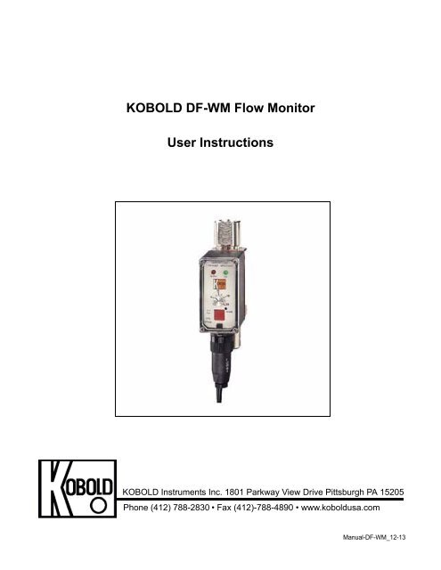
KOBOLD DF-WM Flow Monitor User Instructions
KOBOLD DF-WM Flow Monitor User Instructions
KOBOLD DF-WM Flow Monitor User Instructions

Create successful ePaper yourself
Turn your PDF publications into a flip-book with our unique Google optimized e-Paper software.
<strong>KOBOLD</strong> <strong>DF</strong>-<strong>WM</strong> <strong>Flow</strong> <strong>Monitor</strong><br />
<strong>User</strong> <strong>Instructions</strong><br />
<strong>KOBOLD</strong> Instruments Inc. 1801 Parkway View Drive Pittsburgh PA 15205<br />
Phone (412) 788-2830 • Fax (412)-788-4890 • www.koboldusa.com<br />
Manual-<strong>DF</strong>-<strong>WM</strong>_12-13
<strong>DF</strong>-<strong>WM</strong><br />
Table Of Contents<br />
<strong>KOBOLD</strong> <strong>DF</strong>-<strong>WM</strong> FLOW <strong>Monitor</strong><br />
1.0 General . . . . . . . . . . . . . . . . . . . . . . . . . . . . . . . . . . . . . . . . . . . . . . . . . . . . . 1<br />
2.0 Specifications . . . . . . . . . . . . . . . . . . . . . . . . . . . . . . . . . . . . . . . . . . . . . . . . 2<br />
3.0 Installation <strong>Instructions</strong> . . . . . . . . . . . . . . . . . . . . . . . . . . . . . . . . . . . . . . . . . 5<br />
4.0 Operation . . . . . . . . . . . . . . . . . . . . . . . . . . . . . . . . . . . . . . . . . . . . . . . . . . . 6<br />
4.1 Turning the Unit On . . . . . . . . . . . . . . . . . . . . . . . . . . . . . . . . . . . . . . 6<br />
4.2 Adjustment of the Setpoint. . . . . . . . . . . . . . . . . . . . . . . . . . . . . . . . . 6<br />
4.3 <strong>Flow</strong> Measurement. . . . . . . . . . . . . . . . . . . . . . . . . . . . . . . . . . . . . . . 6<br />
5.0 Arrival of Damaged Equipment . . . . . . . . . . . . . . . . . . . . . . . . . . . . . . . . . . . 7<br />
6.0 Maintenance . . . . . . . . . . . . . . . . . . . . . . . . . . . . . . . . . . . . . . . . . . . . . . . . . 7<br />
7.0 Need Help?. . . . . . . . . . . . . . . . . . . . . . . . . . . . . . . . . . . . . . . . . . . . . . . . . . 7<br />
Diagram 2.4:<br />
List of Diagrams<br />
Sensor Dimensions . . . . . . . . . . . . . . . . . . . . . . . . . . . . . . . 4<br />
Diagram 3.1: Wiring . . . . . . . . . . . . . . . . . . . . . . . . . . . . . . . . . . . . . . . . . . 5<br />
List of Tables<br />
Table 2.1: Material Combinations and Maximum Limits . . . . . . . . . . . . . . . . . . . 2<br />
Table 2.2: Electrical Data. . . . . . . . . . . . . . . . . . . . . . . . . . . . . . . . . . . . . . . . . . 3<br />
Table 2.3: <strong>Flow</strong> Ranges and Fitting Sizes . . . . . . . . . . . . . . . . . . . . . . . . . . . . . 3<br />
P<strong>DF</strong> Rev. 12-13
<strong>DF</strong>-<strong>WM</strong><br />
<strong>KOBOLD</strong> <strong>DF</strong>-<strong>WM</strong> FLOW <strong>Monitor</strong><br />
<strong>User</strong> <strong>Instructions</strong><br />
CAUTION:<br />
For safety reasons, please read the cautionary information located at<br />
the end of the manual, before attempting installation.<br />
1.0 General<br />
The <strong>KOBOLD</strong> <strong>DF</strong>-<strong>WM</strong> flow monitor is intended for use primarily as a flow monitor, with<br />
the additional ability to occasionally meter flow rate.<br />
The <strong>DF</strong>-<strong>WM</strong> uses a paddle wheel to meter flow. The principle of operation is quite<br />
simple; the paddle wheel rotation is calibrated for flow rate. This rotation-flow relationship<br />
is linear in theory. In practice, theory is nearly borne out, leading to a very precise<br />
measuring device. Any nonlinearity is within the stated measurement error of the device.<br />
The paddle wheel approach to flow measurement has the advantage that the instrument<br />
may be installed in any orientation; only the flow direction is specified. Further, this<br />
measurement technique is relatively insensitive to dirt in the medium (ferritic<br />
contaminants, however, must be avoided).<br />
Incorporated in the <strong>DF</strong>-<strong>WM</strong> is a flow setpoint function (with relay) which can be set by the<br />
user to any value within the specified flow range. Through the use of the setpoint<br />
adjustment knob, its accompanying scale, and a momentary switch (the red button), flow<br />
rate may also be approximately determined. This last function is intended for only<br />
occasional use.<br />
P<strong>DF</strong> Rev. 12-13
<strong>DF</strong>-<strong>WM</strong> 2<br />
2.0 Specifications<br />
Table 2.1: Material Composition & Operational Limits<br />
Material<br />
Combination<br />
I II/IIB III IV * VI * VII *<br />
Fittings NPT NPT NPT<br />
NPT or<br />
FLANGE<br />
NPT<br />
NPT or<br />
FLANGE<br />
Housing Trogamid® PSU/PP NP-Brass 316 SS NP-Brass 316 SS<br />
Window Trogamid® PSU/PP Trogamid® PSU NP-Brass 316 SS<br />
Fittings NP-Brass 316 SS/PP NP-Brass 316 SS NP-Brass 316 SS<br />
Locking Pins Brass Brass Brass - - -<br />
O-Rings Buna-N FKM Buna-N FKM Buna-N FKM<br />
Paddle Wheel POM PTFE POM PTFE POM PTFE<br />
Axle<br />
Brass<br />
SS/<br />
Ceramic<br />
Brass 316 SS Brass 316 SS<br />
Axle Bearing PTFE PTFE PTFE PTFE PTFE PTFE<br />
Orifice PTFE 2 PTFE 2 PTFE 2 PTFE 2 PTFE 2 PTFE 2<br />
STANDARD VERSION<br />
HIGH PRESSURE<br />
VERSION<br />
Maximum<br />
Pressure<br />
145 PSIG<br />
145/85<br />
PSIG<br />
230 PSIG 230 PSIG 1450 PSIG<br />
1450 PSIG<br />
or<br />
580 PSIG<br />
with flange<br />
Maximum<br />
Temperature<br />
145°F 180°F 180°F 180°F 180°F 180°F<br />
* Fittings not Rotatable Abbreviations: PP - Polypropylene<br />
2<br />
SS on Model <strong>DF</strong>-XX01 GFR - Glass Fiber Reinforced<br />
NP<br />
PSU<br />
- Nickel Plated<br />
- Polysulfone<br />
P<strong>DF</strong> Rev. 12-13
3 <strong>DF</strong>-<strong>WM</strong><br />
Table 2.2: Electrical Data<br />
Power Supply (as specified):<br />
Power Consumption:<br />
Relay:<br />
Maximum Voltage:<br />
Maximum Load:<br />
24 VDC, 24 VAC, 110VAC, 230 VAC<br />
(+15% / -10%)<br />
3.5 W max.<br />
250V<br />
5A<br />
Operating Temperature:<br />
Wiring Connection:<br />
-25° to 80°C (-25° to 60°C for <strong>DF</strong>-81..)<br />
-10° to 180°F (-10° to 140°F for <strong>DF</strong>-81..)<br />
5 Ft. PVC Cable (Standard),<br />
Plug with mating connector (Optional)<br />
Environmental Protection: IP65 (equivalent to NEMA 4)<br />
Table 2.3: <strong>Flow</strong> Ranges & Fitting Sizes<br />
Sensor<br />
Model<br />
Number<br />
Range<br />
Water GPM<br />
Standard<br />
Fittings<br />
NPT<br />
Special<br />
Fitting<br />
Suffix “B”<br />
Orifice<br />
Diameter<br />
Inches<br />
Pressure<br />
Drop PSI<br />
<strong>DF</strong>-XX01 0.02 - 0.14 1/8" 1/4" 0.04 10.2<br />
<strong>DF</strong>-XX02 0.05 - 0.30 1/4" 3/8" 0.08 4.2<br />
<strong>DF</strong>-XX03 0.05 - 0.60 1/4" 3/8" 0.08 10.4<br />
<strong>DF</strong>-XX04 0.1 - 0.7 1/4" 3/8" 0.11 9.6<br />
<strong>DF</strong>-XX05 0.2 - 2.5 3/8" 1/2" 0.19 12.1<br />
<strong>DF</strong>-XX06 0.4 - 5.0 1/2" 3/4" 0.32 2.9<br />
<strong>DF</strong>-XX07 0.5 - 6.0 3/4" 1" 0.32 4.4<br />
<strong>DF</strong>-XX08 0.5 - 12 3/4" 1" 0.49 4.4<br />
<strong>DF</strong>-XX09 1.0 - 25 1-1/4" 1-1/2" 0.49 15.9<br />
<strong>DF</strong>-XX10 1.5 - 36 1-1/4" 1-1/2" 0.73 13.5<br />
P<strong>DF</strong> Rev. 12-13
<strong>DF</strong>-<strong>WM</strong> 4<br />
Diagram 2.4: Sensor Dimensions<br />
1.89”<br />
6.5” (Flanged: 7.87”)<br />
3.54”<br />
0.88” 3.48”<br />
P<strong>DF</strong> Rev. 12-13
5 <strong>DF</strong>-<strong>WM</strong><br />
3.0 Installation <strong>Instructions</strong><br />
CAUTION:<br />
For safety reasons, please read the cautionary information located at<br />
the end of the manual, before attempting installation.<br />
To install, proceed as follows:<br />
1. Make sure that the actual flow rate in your system lies within the flow range of<br />
the instrument. The flow range can be read off the identification tag. <strong>Flow</strong> rates<br />
in excess of 120% of the range maximum will, in continuous use, lead to<br />
bearing and paddle damage.<br />
2. Ensure that the power supply voltage is in accordance with that specified on<br />
the identification tag. Electrical connections are made using the standard 5-<br />
wire cable (or via the optional 6-pin plug) as specified by the following wiring<br />
diagram:<br />
Diagram 3.1: Wiring<br />
Cable Connection Plug Connection<br />
Wire 1: AC Power, DC Power (-)<br />
Wire 2: AC Power, DC Power (+)<br />
Wire 3: Relay N/O Contact<br />
Wire 4: Relay Common<br />
Wire 5: Relay N/C Contact<br />
You are now ready to mechanically connect the unit.<br />
1. The media flow direction is indicated by an arrow on the housing. The flow sensor<br />
may be mounted in any orientation as long as the front face of the device remains in<br />
a vertical plane. No straight run is required.<br />
2. The flow sensor must be mounted so that the measuring housing normally<br />
remains filled with fluid during operation. We recommend mechanically mounting the<br />
sensor approximately 2” from each connection.<br />
2. Take care not to place stresses on the housing both during installation. An<br />
appropriate pipe thread sealer is recommended for all threaded connections. Use a<br />
wrench to hold the instrument fittings static while you tighten the fittings on your pipe.<br />
3. Should there be small amounts of ferrite contaminants in the medium, we<br />
recommend the installation of our magnetic filter (type MFR- or equivalent).<br />
4. Medium should always be introduced to the system slowly to avoid pressure<br />
surges which could damage the instrument.<br />
P<strong>DF</strong> Rev. 12-13
<strong>DF</strong>-<strong>WM</strong> 6<br />
4.0 Operation<br />
The device is delivered fully calibrated and ready for use. The calibration screws (found<br />
inside the electronics housing), MUST NOT be adjusted by the user. Customer<br />
adjustment of these screws necessitates a recalibration of the unit. The precision of the<br />
instrument is guaranteed only if the calibration screws have not been adjusted.<br />
Modification of the sensor (by physically modifying or replacing sensor components)<br />
requires recalibration of the unit if the specified accuracy is to be maintained.<br />
4.1 Turning the Unit On<br />
The device is operational as soon as it is wired into a power supply. A green "ON"<br />
LED indicates that power is present at the unit by lighting up.<br />
4.2 Adjustment of the Setpoint<br />
To adjust the setpoint, simply align the indicator mark on the potentiometer knob<br />
on electronics panel), with the desired flow value on the scale. Flashing of the red<br />
"ALARM" LED indicates that the media flow is below the setpoint value<br />
4.3 <strong>Flow</strong> Measurement<br />
The <strong>DF</strong>-<strong>WM</strong> is primarily a flow monitoring device (i.e., it signals an alarm when a<br />
preset flow limit is/is not met). It can, however, be used to measure flow. This is<br />
done as follows:<br />
1.Depress the square red button on the face of the unit. This disengages the<br />
setpoint relay.<br />
2. Turn the potentiometer from the smallest to the largest flow value on the flow<br />
scale, until the red LED starts to flash. The flow rate may now be read off the<br />
potentiometer scale.<br />
3.Reset the potentiometer to the desired setpoint value.<br />
4.Release the red button.<br />
Note: After the setpoint has been adjusted, or the flow rate measured, it is important that<br />
the lid on the face of the electronics housing is resealed tightly. This ensures that<br />
protection according to IP 65 is maintained.<br />
P<strong>DF</strong> Rev. 12-13
5.0 Arrival of Damaged Equipment<br />
7 <strong>DF</strong>-<strong>WM</strong><br />
Your instrument was inspected prior to shipment and found to be defect-free. If damage<br />
is visible on the unit, we advise that you carefully inspect the packing in which it was<br />
delivered. If damage is visible, notify your local carrier at once, since the carrier is liable<br />
for a replacement under these circumstances. If your claim is refused, please contact<br />
Kobold Instruments for further advisement.<br />
6.0 Maintenance<br />
The <strong>KOBOLD</strong> <strong>DF</strong>-<strong>WM</strong> requires little maintenance provided the measured medium is<br />
kept free of contaminants. In particular, ferritic pollutants can cause problems for this<br />
device due to the incorporation of magnets into the paddle wheel. To avoid this, we<br />
recommend the installation of a magnetic filter, such as Kobold's model MFR or<br />
equivalent.<br />
Do NOT tamper with the electronics as this voids your warranty.<br />
7.0 Need help with your <strong>DF</strong>-<strong>WM</strong> <strong>Flow</strong>meter?<br />
Call one of our friendly engineers at 412-788-2830.<br />
P<strong>DF</strong> Rev. 12-13
<strong>DF</strong>-<strong>WM</strong> 8<br />
P<strong>DF</strong> Rev. 12-13
9 <strong>DF</strong>-<strong>WM</strong><br />
Caution<br />
PLEASE READ THE FOLLOWING GENERAL FLOW METER / MONITOR<br />
WARNINGS BEFORE ATTEMPTING INSTALLATION OF YOUR NEW<br />
DEVICE. FAILURE TO HEED THE INFORMATION HEREIN MAY<br />
RESULT IN EQUIPMENT FAILURE AND POSSIBLE SUBSEQUENT<br />
PERSONAL INJURY.<br />
P<strong>DF</strong> Rev. 12-13
<strong>DF</strong>-<strong>WM</strong> 10<br />
• <strong>User</strong>'s Responsibility for Safety: <strong>KOBOLD</strong> manufactures a wide range of<br />
process sensors and technologies. While each of these technologies are<br />
designed to operate in a wide variety of applications, it is the user's<br />
responsibility to select a technology that is appropriate for the application,<br />
to install it properly, to perform tests of the installed system, and to maintain<br />
all components. The failure to do so could result in property damage or<br />
serious injury.<br />
• Inspect instrument for damage upon arrival: Cracked, fractured, bent or<br />
otherwise damaged instruments must not be put into use, since the device<br />
is weakened to an unknown extent. Refer to Section 5.0, Arrival of<br />
Damaged Equipment, for additional information.<br />
• Media and Chemical Compatibility: The maximum tolerances of the<br />
device have been determined using water. If using other media, especially<br />
corrosive media, it is critically important that the user determine chemical<br />
compatibility with our instruments. <strong>KOBOLD</strong> Instruments Inc. cannot<br />
accept responsibility for failure and consequences resulting from use of<br />
media other than water.<br />
• Material Compatibility: Make sure that the model which you have<br />
selected is chemically compatible with the application liquids. While the<br />
meter is liquid and spray resistant when installed properly, it is not<br />
designed to be immersed.<br />
• Proper Installation in <strong>Flow</strong> System: Install the device in a fully supported<br />
position within your flow system. This avoids excessive stresses which may<br />
damage the instrument. In particular:<br />
a.) Ensure that the plumbing leading to and from the instrument is fully<br />
supported and that the instrument does not perform the physical function of<br />
a joint.<br />
b.) When calculating stress on the device caused by plumbing, the weight<br />
of the medium in the pipes must be considered as well.<br />
c.) Misaligned runs of rigid piping can cause large stresses when<br />
connected to the instrument. Do not connect in such a fashion.<br />
d.) When connecting fittings, hold the instrument fittings rigid with a<br />
correctly sized wrench. Do not install by twisting the instrument into the<br />
pipe fittings.<br />
e.) Do NOT install by holding the device housing to provide counter-torque<br />
to the pipe fitting.<br />
f.) Use an appropriate amount of PTFE tape on male threads of fitting. This<br />
reduces the twisting stresses produced by tightening the fittings into each<br />
other.<br />
g.) Do not use pliers or wrenches on the housing, as this may damage it.<br />
h.) Do not overtighten, as this may fracture the fittings.<br />
P<strong>DF</strong> Rev. 12-13
11 <strong>DF</strong>-<strong>WM</strong><br />
• While Operating the <strong>Flow</strong> System: During operation, there are a number<br />
of situations to avoid:<br />
a.) The sudden cessation of fluid flow causes what is typically referred to<br />
as "water hammer". Most people are familiar with this phenomenon from<br />
their home experience - it is the cause behind the loud clank of water pipes<br />
which occurs when faucets are turned off too suddenly. The cause behind<br />
this "water hammer" is quite easy to visualize. Water is fairly massive. The<br />
amount of water in long runs of pipe is quite substantial. When the faucets<br />
are turned off suddenly, especially from a full on condition, the water has<br />
considerable momentum and does not want to stop flowing. The situation<br />
is similar to stopping a car by running into a wall, rather than by applying<br />
brakes. Both are sudden rather than gradual. The damage to the wall can<br />
be substantial (not to mention the car).<br />
b.) The "water hammer" causes surges in fluid pressure which could cause<br />
the measurement instrument's pressure limit to be exceeded, resulting in<br />
failure and possible personal injury.<br />
c.) Fluid surges, as well as the water hammer, can be particularly<br />
damaging to empty flowmeters since there is no back pressure in the<br />
device. The damage is caused, once again, by momentary excess<br />
pressure. To avoid these surges, fluid lines should remain full (if possible)<br />
and water flow should be introduced to the device slowly.<br />
d.) If the instrument is isolated with inlet and outlet valves, the flowmeter<br />
must be completely drained when said valves are both closed. Failure to<br />
do so could result in damage to the device caused by thermal expansion of<br />
fluid.<br />
e.) Freezing of water in the instrument must be avoided since the resultant<br />
expansion will damage the flowmeter and make it unsafe for use.<br />
• Wiring and Electrical: Section 2.0, Specifications and Section 3.0,<br />
Installation <strong>Instructions</strong>, provide the voltage and current limitations and the<br />
wiring for the various sensor types. The sensor electrical ratings should<br />
never be exceeded. Electrical wiring of the sensor should be performed in<br />
accordance with all applicable national, state and local codes.<br />
• Temperature and Pressure: Section 2.0, Specifications, provides the<br />
temperature and pressure limits for each model. Operation outside these<br />
limitations will cause damage to the unit and can potentially cause personal<br />
injury. Fluid should never be allowed to freeze inside the sensor.<br />
• Make a Fail-safe System: Design a fail-safe system that accommodates<br />
the possibility of switch or power failure. In critical applications, <strong>KOBOLD</strong><br />
recommends the use of redundant backup systems and alarms in addition<br />
to the primary system.<br />
P<strong>DF</strong> Rev. 12-13